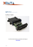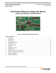
1
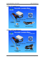
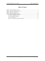
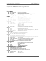
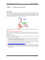
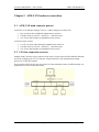
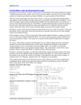
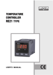
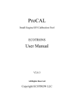
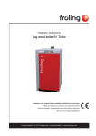
Accurate Lambda Meter - with CAN bus ALM-CAN Manual V2.2 ALM-CAN Accurate Lambda Meter __ With CAN bus Manual V2.2 ECTORONS LLC COPY RIGHT ECOTRONS LLC ALL RIGHT RESERVED www.ecotrons.com Copyright ECOTRONS LLC Page 1 of 15 Accurate Lambda Meter - with CAN bus ALM-CAN Manual V2.2 Check before you power on ALM-CAN: The oxygen sensor is installed in the right way; or if it's left in the free air, make sure it's dry and it's not close to the inflammable materials. The ALM-CAN is correctly connected to DC power supply or 12V battery; Website: http://www.ecotrons.com Email: [email protected] www.ecotrons.com Copyright ECOTRONS LLC Page 2 of 15 Accurate Lambda Meter - with CAN bus ALM-CAN Manual V2.2 ALM-CAN included parts: ALM-CAN-II included parts: www.ecotrons.com Copyright ECOTRONS LLC Page 3 of 15 Accurate Lambda Meter - with CAN bus ALM-CAN Manual V2.2 Table of Content Chapter 1 ALM-CAN Product Overview ............................................................................................... 5 Chapter 2 ALM-CAN technical specifications ....................................................................................... 8 Chapter 3 Appearance and dimension ..................................................................................................... 9 Chapter 4 Protect your oxygen sensor .................................................................................................. 10 Chapter 5 ALM-CAN hardware connections.........................................................................................11 5.1 ALM-CAN main connector pin-out .........................................................................................11 5.2 CAN bus connection overview ................................................................................................11 5.3 CAN communication settings ................................................................................................. 13 5.4 ANOUT Calibration ................................................................................................................ 13 5.5 How to verify analog voltage matching lambda ..................................................................... 14 www.ecotrons.com Copyright ECOTRONS LLC Page 4 of 15 Accurate Lambda Meter - with CAN bus ALM-CAN Manual V2.2 Chapter 1 ALM-CAN Product Overview ALM (Accurate Lambda Meter) is an air-fuel-ratio (AFR) meter which uses the Bosch LSU4.9 wideband oxygen sensor and Bosch semiconductor chip CJ125 to accurately measure the AFR or lambda for variant combustion engines. ALM-CAN is the version that comes with the auto industry standard CAN bus. This is the only wideband controller equipped with the CAN bus available to the after-market. The CAN bus has been widely used in auto industries and especially in engine control systems for a few decades. There are tons of CAN bus based communication protocols published by SAE, ISO, CARB (California Air Resource Board). Multiple oxygen sensor based signals have been defined in those protocols. One specific protocol, SAE J1939, defines the oxygen concentration in the exhaust gas, which can be broadcasted by the sensor control module, or a wideband controller. By default, our ALM-CAN supports SAE J1939 protocol, and broadcasts O2 concentration. Furthermore it broadcasts lambda, sensor temperature, and sensor fault codes, etc. ALM-CAN can also be customized to follow OEM specific CAN protocols if needed. Our ALM-CAN has been used in many specific engine applications or gas analyzing applications, where the main controller has already used the CAN bus to communicate with other control modules. ALM-CAN is kind of a perfect plug-and-play unit for the CAN bus based application. Any controller on the CAN bus can read the broadcasted O2% or Lambda, or other sensor info without any hardware changed. The protocols can be either standard, or customized. We do provide the customization of the protocols for small manufacturer applications. Meanwhile, ALM-CAN has a dual-channel version: ALM-CAN-II. It includes 2x LSU 4.9 sensors, can simultaneously measure the O2% of the two channels, driven by Bosch CJ125 chips. It is typically used for V-shape engines, like V6, V8 or V10 engines, etc. Another big advantage of the CAN bus communication to the 0-5V analog voltage output is accuracy. The CAN bus completely eliminates all the errors created by DAC (Digital to Analog Conversion) and ADC (Analog to Digital Conversion) conversions. The errors created by DAC and ADC alone can be as big as 0.02 lambda, depending on many factors here: your 5V reference voltage, which always has some errors, and your DAC, ADC chips, which are mostly 10 bit length and have rounding errors. Honestly, all wideband controllers that use the 0-5V analog output cannot be called "professional", because no OEM application uses that. ALM-CAN comes by default in a sealed and solid case. It can work in very harsh environment, like -40 C to +125 C temperature; and severe vibrations. It is water submersible and meets the IP67 water-proof standard. You can also request to add a LED display to ALM-CAN and make it lab environment equipment. Again, ALM-CAN uses the more advanced LSU4.9 sensor instead of a LSU4.2 which is still used by most other wideband controllers. LSU4.9 is the new generation wideband sensor. It is superior to LSU4.2. One obvious proof is: Bosch uses LSU4.9 across the board for their wideband applications. Here is why LSU4.9 is superior to LSU4.2: http://www.ecotrons.com/technology/bosch_lsu_49_is_superior_to_lsu_42_sensors/ ALM-CAN can also use LSU4.9D sensor, but the need to update the software, if you need to use LSU4.9D, please explain in advance at the time of purchase ALM. Second, Bosch chip CJ125 is the integrated chip (IC) specifically designed for LSU 4.9/4.2 Sensors. Bosch's own wideband controller, "LambdaTronic", uses CJ125 driver chip. In fact, Bosch uses this www.ecotrons.com Copyright ECOTRONS LLC Page 5 of 15 Accurate Lambda Meter - with CAN bus ALM-CAN Manual V2.2 chip wherever a LSU sensor is used. The CJ125 and LSU sensor are mated-pair by Bosch. Presumably LSU sensors work the best with CJ125 chips. See here for Bosch Motorsport’s wideband controller, LT4: http://www.bosch-motorsport.de/media/catalog_resources/Function_Manual_LT4pdf.pdf List of ALM-CAN parts Small ALM controller with CAN bus built-in Large LED display (optional, for lab environment) Harness (60in default, 120in optional) Bosch LSU 4.9 sensor (ALM-CAN: one; ALM-CAN-II: two) Sensor plug and bung (ALM-CAN: one; ALM-CAN-II: two) CAN communication cable USB-CAN-Z converter (optional) CD - documents and ALM GUI software (CAN bus based) www.ecotrons.com Copyright ECOTRONS LLC Page 6 of 15 Accurate Lambda Meter - with CAN bus Products ALM-CAN Manual V2.2 O2 Sensor Channels supported ANOUT(Range) Communication Display RS232 AFR Gauge 1 YES(0 ~ 5v) LSU 4.9(default)/ADV NO NO YES YES SCI(0 ~ 5v) NO 1 YES(0 ~ 5v) LSU 4.9(default)/ADV NO NO NO NO CAN NO 1 NO LSU 4.9(default)/ADV NO NO NO NO ALM-B-RS485 RS485 NO 1 NO LSU 4.9(default)/ADV NO NO NO NO ALM-LED RS232 LED (4 bit) 1 YES(0 - 5v) LSU 4.9(default)/ADV NO NO YES YES ALM-CAN CAN NO 1 NO LSU 4.9(default)/ADV NO NO NO NO ALM-CAN-II CAN NO 2 NO LSU 4.9(default)/ADV NO NO NO NO ALM-II RS232 LCD(128*64) 2 YES(0 - 5v) LSU 4.9(default)/ADV NO NO YES YES ALM-LD RS232/CAN/USB LCD(640*480) 2 YES(0 - 10v) LSU 4.9(default)/ADV YES YES YES YES ALM-Gauge ALM-B-ANOUT ALM-B-CAN O2 Sensor Supported Virtual Exhaust Exhaust Engine narrow band o2 temperature pressure Speed sensor sensor sensor Input output(NBOUT) Note: Blue font represents the current user manual supported of ALM units. www.ecotrons.com Copyright ECOTRONS LLC Page 7 of 15 Accurate Lambda Meter - with CAN bus ALM-CAN Manual V2.2 Chapter 2 ALM-CAN technical specifications Power supply Input voltage range Input current Voltage protection Load Dump Clamp DC9V~15V (12V Typical) 60mA typical plus the heater current Reverse polarity protected, & over voltage protected Maximum Voltage Sensors Compatible Number of Sensors Free air calibration LSU4.9 (Support LSU4.9D, LSU 4.2 capable but not recommended) ALM-CAN: one; ALM-CAN-II: two No need (it measures the free air O2%) Accuracy Lambda range Lambda accuracy Air/Fuel Ratio λ = 0.5 ~ ∞ (Gasoline AFR: 7.35 to free air) ±0.008 @ λ=1.00 ±0.01 @ λ=0.80 ±0.05 @ λ=1.70 Fuel dependent (see lambda range and accuracy) Control Current Heater return (H-) Built-in PID control with CJ125 Typical 1A; Max 1.7A (ALM-CAN-II: Typical 1.7A; Max 3.6A) Standalone Heater return wire Heater Response time Lambda 5ms updating rate (everything finished in 5ms) 250k, 500k, 1M CAN bus baud rate configurable Output CAN bus signals, default SAE J1939 protocols Broadcasted signalsO2 concentration, lambda, sensor temperature, and sensor fault codes Signal accuracy All 16 bit values Lambda analog output 0~5V user programmable (optional, not included) Data logging Compatible to any CAN bus based data logger User-friendly PC software for configurations and customer settings Main-Processor CPU Speed Memory Freescale MC9S12P128 16-bit micro-processor (Auto industry rated) 32MHz 128k Flash, 6k RAM, 4k Data Special features of ALM wideband sensor On-Board-Diagnosis and error report Self-learning of part-to-part variations, aging effect Working with different types of fuels (gasoline, diesel, E85, etc) General Temperature range Dimensions www.ecotrons.com -40oC ~ 125oC 4.0 " x 2.6" x 1.0" Copyright ECOTRONS LLC Page 8 of 15 Accurate Lambda Meter - with CAN bus Chapter 3 ALM-CAN Manual V2.2 Appearance and dimension ALM-CAN /ALM-CAN-II dimension www.ecotrons.com Copyright ECOTRONS LLC Page 9 of 15 Accurate Lambda Meter - with CAN bus Chapter 4 ALM-CAN Manual V2.2 Protect your oxygen sensor Installation Correct installation of the oxygen sensors is a must to avoid sensor damage. It protects the oxygen sensor from condensations and gives the sensor longer life. It also can make the measurement more accurate. The sensor body should be perpendicular to the exhaust gas flow, and it should also be tilted in the range of 10o~75o from the horizontal line (see below figure). The typical tilt-angle is 30o. The sensor head should be close to the center of the exhaust pipe. After finding the right location on the exhaust pipe, drill a hole of 18 mm in diameter. Weld the sensor bung on it. Note: do not weld the bung with the sensor in it. Note, if you vehicle has a Bosch narrow band oxygen sensor (LSF) already you can just un-plug the LSF, and plug-in the wideband LSU sensor into the hole. Bosch LSU and LSF have the same size of the thread. More User Notes LSU sensors are not designed to work with leaded gasoline. Using LSU sensor with leaded gasoline will reduce the sensor life. With the LSU sensor installed in the exhaust pipe, whenever the engine is running, please also run ALM-CAN, which controls the LSU heater. Otherwise, long-time-running engine with LSU sensor not heated can cause damage of the sensor. LSU sensor is preferred to run within the temperature range of 500~900oC, the best temperature is 780oC. Too high temperature (>1030oC) will cause damage of the sensor. Refer to Bosch LSU4.9 data for more details about the variant temperature requirements. http://www.etas.com/en/downloadcenter/5858.php Avoid heating the LSU sensor before the engine is running. At the engine start, there may be condensations in the exhaust gas, which can cause damage of the sensor. The preferred order: start the engine first, then immediately turn on the ALM-CAN, which will ramp up the heating power smoothly. www.ecotrons.com Copyright ECOTRONS LLC Page 10 of 15 Accurate Lambda Meter - with CAN bus ALM-CAN Manual V2.2 Chapter 5 ALM-CAN hardware connections 5.1 ALM-CAN main connector pin-out ALM-CAN is a weatherproof design. There are 3 cables coming out of ALM-CAN: LSU 4.9 sensor cable with Bosch standard sensor connector CAN bus which are CAN-H and CAN-L twisted wire pair 12V+ Power and Ground wires (standalone Heater return) ALM-CAN-II has 4 cables: 2 x LSU 4.9 sensor cable with Bosch standard sensor connector CAN bus which are CAN-H and CAN-L twisted wire pair 12V+ Power and Ground wires (standalone Heater return) 5.2 CAN bus connection overview Multiple ALM-CAN units can be connected on the same CAN bus; their ALM IDs should be different, and can be configured via a PC GUI interface. About ALM-CAN CAN communication settings, please refer to ALM GUI manual. Keep in mind, ALM-CAN does not come with a CAN bus termination resistor (120 Ω) internally. It is assumed the user CAN bus has that already. www.ecotrons.com Copyright ECOTRONS LLC Page 11 of 15 Accurate Lambda Meter - with CAN bus ALM-CAN Manual V2.2 1) Connect the 6-pin LSU4.9 mating connector to the O2 sensor. If you are using ALM-CAN-II, need to connect the two O2 sensors. 2) Connect ALM-CAN to the CAN bus. Yellow wire is CAN-L; Dark Green wire is CAN-H. 3) Connect the 12V+ to 12V battery plus or the DC power supply +; 4) Connect the GND (and heater return ground) to 12V battery minus or the DC power supply negative ; Note: 1) User’s CAN bus must have 120 ohm terminal resistors; 2) The default CAN bus baud rate is 250K; this can be configured to 500k and 1M via PC GUI. 3) If you want to communicate with your computer, you can use ECOTRONS USB-CAN-Z converter (Refer to ECOTRONS USB-CAN-Z User's Guide). Users can connect ALM-CAN to ALM GUI via CAN bus, use ALM GUI, users can: change CAN ID, beat rate; display Lambda, O2%, O2 sensor temperature; read fault codes; record and playback data, etc. About ALM GUI usage, please refer to the [ALM GUI Manual]. www.ecotrons.com Copyright ECOTRONS LLC Page 12 of 15 Accurate Lambda Meter - with CAN bus ALM-CAN Manual V2.2 5.3 CAN communication settings ALM-CAN CAN communication default broadcast two PGN data: PGN65280 and PGN61454, they have different ID. PGN1 (65280), the default ID is 0x0CFF0001, PGN2 (61454), the default ID is 0x18F00E01. ALM-CAN-II can simultaneously measure the O2% of the two channels; each channel broadcast 2 PGN, two CAN channels totaling 4 PGN. They have different ID, channel 1 PGN1 (65280), the default ID is 0x0CFF0001, channel 1 PGN2 (61454), the default ID is 0x0CF00E01; channel 2 PGN1 (65281), the default ID is 0x0CFF0002, channel 2 PGN2 (61455), the default ID is 0x0CF00E02. PGN65280 and PGN65281 are Ecotrons Specified Information; they are subset SAE J1939 protocols or the customized subsets. The default CAN bus Baud Rate is 250kbs, extended frame. About CAN communication protocol, please refer to [ALM Communication Protocol – CAN]. 5.4 ANOUT Calibration Lambda mode, ANOUT used to indicate changes in lambda, the default setting: 0.00 Volt at Lambda 0.50 5.00 Volt at Lambda 2.00 AFR mode, ANOUT used to indicate changes in AFR, the default setting: 0.00 Volt at AFR 7.35 5.00 Volt at AFR 29.4 www.ecotrons.com Copyright ECOTRONS LLC Page 13 of 15 Accurate Lambda Meter - with CAN bus ALM-CAN Manual V2.2 O2% mode, ANOUT used to indicate changes in O2%, the default setting: 0.00 Volt at O2% -20.99 5.00 Volt at O2% 20.99 If customers want to modify these parameters, customers can refer to ALM GUI Manual 2.4 ALM GUI using COM or USB communication. http://www.ecotrons.com/files/ALM%20GUI%20Manual.pdf Note:The limit range of analog voltage is 0-5v. The value of lambda is 0.5-16. The low voltage must match the low Lambda. You can’t make 5V match 0.5 Lambda. AFR and O2% are same with Lambda. 5.5 How to verify analog voltage matching lambda Since you have 2 ALMs, the way to compare is easy.You can either cross check 2 ALMs with the same sensor, or cross check 2 sensors, with 1 ALM. And the next step to check good lambda: 1) Put the sensor in the free air, and use ALM GUI , to read the O2%;if it is close to 20% ;the ALM and sensor is good, otherwise, you could do Free air calibration. www.ecotrons.com Copyright ECOTRONS LLC Page 14 of 15 Accurate Lambda Meter - with CAN bus ALM-CAN Manual V2.2 2) If ALM GUI gives good O2%, then measure the ANOUT analog voltage, with a voltage meter, convert that voltage back to lambda, and compare it against the lambda in the ALM GUI. This is to verify the analog voltage is really matching the lambda measured. www.ecotrons.com Copyright ECOTRONS LLC Page 15 of 15