1
99 Washington Street
Melrose, MA 02176
Fax 781-665-0780
TestEquipmentDepot.com
USER’S MANUAL. PROLINK-2 Premium
O F
C O N T E N T S
1
GENERAL ...............................................................................................................1
1.1 Description ........................................................................................................1
1.2 Specifications....................................................................................................3
2
SAFETY RULES .....................................................................................................9
2.1 General safety rules ..........................................................................................9
2.2 Descriptive Examples of Over-Voltage Categories ..........................................11
3
INSTALLATION.....................................................................................................13
3.1 Power Supply..................................................................................................13
3.1.1 Operation using the External DC Charger .................................................13
3.1.2 Operation using the Battery.......................................................................13
3.1.2.1
Battery Charging..............................................................................14
3.2 Installation and Start-up ..................................................................................14
4
OPERATING INSTRUCTIONS..............................................................................15
4.1 Description of the Controls and Elements........................................................15
4.2 Adjustment of Volume and Monitor Parameters...............................................23
4.3 Selecting the Operation Mode: TV / Spectrum Analyser ..................................23
4.4 RF Band Selection: 45-862 MHz / 900-2150 MHz ..........................................23
4.5 Channel Tuning / Frequency Tuning................................................................24
4.6 Automatic Transmission Search ......................................................................24
4.7 Selecting Analogue / Digital Mode...................................................................24
4.8 External Units Power Supply (EXT. SUPPLY) .................................................25
4.9 TV Operating Mode .........................................................................................26
4.9.1 Selecting the Measurement Mode (MEASURE) ........................................26
4.9.1.1
Measuring the Video Carrier Level (Level) .......................................28
4.9.1.1.1 Changing the measurement information format ............................29
4.9.1.1.2 Selecting TV Mode: TV, LV, SY (TV MODE).................................29
4.9.1.2
Measuring the Video / Audio Ratio (V/A)..........................................31
4.9.1.3
Measuring the Carrier / Noise Ratio (C/N)........................................32
4.9.1.4
Measuring the Power of Digital Channels (Channel power) .............34
4.9.1.5
BER measurement mode selection..................................................35
4.9.1.5.1 Measuring BER of COFDM Digital Channels (COFDM)................36
4.9.1.5.2 Measuring BER of QPSK Digital Channels (QPSK) ......................40
4.9.2 TV Mode Functions Menu .........................................................................44
4.9.2.1
Selection of the RF Band: (Band switching) .....................................45
4.9.2.2
Selection of the TV System and Standard (System & Standard) ......45
4.9.2.3
Battery and External Units Power Supply (BATTERY & LNB)..........46
4.9.2.4
Input Video ......................................................................................46
4.9.2.5
Selecting the Channels Table (Channel set) ....................................47
English
T A B L E
USER’S MANUAL. PROLINK-2 Premium
4.9.2.6
Measurement Units..........................................................................47
4.9.2.7
Power Off Mode (Manual power) .....................................................47
4.9.2.8
C/N setup ........................................................................................47
4.9.2.9
Channel Bandwidth (Channel BW) ..................................................48
4.9.2.10 LNB Local Oscillator Frequency (Lnb local osc)...............................48
4.9.2.11 Video Polarity ..................................................................................48
4.9.2.12 Verification of distribution networks (SAT IF Test)............................49
4.9.2.13 NICAM Channel...............................................................................51
4.9.2.14 Search Level ...................................................................................51
4.9.2.15 Teletext ...........................................................................................51
4.9.2.16 DiSEqC Command Generator..........................................................52
4.9.2.17 Beep................................................................................................55
4.9.2.18 Equipment Information.....................................................................55
4.9.2.19 Exit ..................................................................................................55
4.10 Spectrum Analyser Operating Mode................................................................55
4.10.1 Spectrum Analyser Mode Functions Menu ................................................57
4.10.1.1 Band Switching................................................................................57
4.10.1.2 Span................................................................................................57
4.10.1.3 Reference Level ..............................................................................58
4.10.1.4 Dual Marker/Single Marker ..............................................................58
4.10.1.5 Sweep .............................................................................................58
4.10.1.6 Reference Noise (Carrier
Ref. Noise)..........................................59
4.10.1.7 Channel Bandwidth (Marker
Channel BW)..................................59
4.10.1.8 Marker (Channel BW Marker........................................................59
4.10.1.9 Carrier (Ref. Noise
Carrier) .........................................................59
4.10.1.10 Bandwidth of the Spectrum Measuring Filter (Measure bandwidth)..60
4.10.1.11 Selecting the Channels Table (CHANNEL SET) ..............................60
4.10.1.12 Batteries and External Units Power Supply (BATTERY & LNB) .......60
4.10.1.13 Exit ..................................................................................................60
4.10.2 Selecting the Measurement Mode.............................................................60
4.10.2.1 Measuring Carrier Levels (Level) .....................................................61
4.10.2.2 Measuring the Carrier / Noise ratio (C/N Referenced)......................61
4.10.2.3 Measuring the Power of Digital Channels (Channel Power) .............62
4.11 Selecting the Sound Mode (SOUND) ..............................................................63
4.11.1 FM function, access to RDS service..........................................................65
4.11.2 Tone function ............................................................................................65
4.11.3 Selecting NICAM sound ............................................................................65
4.12 Measurement Configuration Memories............................................................66
4.12.1 Storing a Measurement Configuration (STORE)........................................66
4.12.2 Retrieving a Configuration (RECALL)........................................................67
4.13 Direct Access to Functions ..............................................................................68
4.14 Printing the Spectrum......................................................................................68
4.14.1 Handshake and Control Lines ...................................................................69
4.14.2 CI-23 set-up ..............................................................................................70
Î
Î
Î
Î
5
DESCRIPTION OF THE INPUTS AND OUTPUTS ................................................71
5.1 RF input ..........................................................................................................71
5.2 RS-232C serial port.........................................................................................71
5.3 Scart (DIN EN 50049) .....................................................................................72
6
MAINTENANCE ....................................................................................................73
6.1 Internal fuses which user cannot replace.........................................................73
6.2 Replacing the Battery ......................................................................................73
6.3 Cleaning Recommendations ...........................................................................74
English
USER’S MANUAL. PROLINK-2 Premium
USER’S MANUAL. PROLINK-2 Premium
ADVANCED TV & SAT
LEVEL METER
PROLINK-2 Premium
1
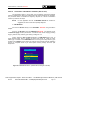
1 GENERAL
Description
The result of uniting PROMAX ELECTRONICA’s long experience in the design
of TV signal analysers with the latest in technological progress, the PROLINK-2
Premium brings together the functions installers seek most, all in one small,
light-weight, portable instrument.
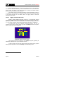
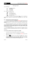
Special attention has been given to creating a level meter that has advanced
features, but which is also easy to use. Three features in particular are a result of this:
a universal keyboard, each function represented by a graphic icon, so that after a brief
period of introduction to the instrument, access to any function becomes almost
intuitive. Secondly, the meter has been entirely designed as an On Screen Display
(OSD) instrument so that, when a function is selected, it appears on the monitor listing
all the various parameters the user has chosen. Finally, there is a rotary selector-button
used for navigation across the different on-screen menus, to alter parameters and to
validate them at the touch of a button.
The range of frequencies covered, from 45 to 862 MHz and from 900 to
2150 MHz, makes PROLINK-2 Premium an excellent instrument for FM radio,
terrestrial TV (MATV ’Master Antenna Television’), cable TV (CATV, 'Community
Antenna Television'), satellite TV, MMDS microwave links, VSAT ('Very Small
Aperture Terminal') systems and digital TV. Furthermore, its high resolution frequency,
50 kHz, makes FM measurements much easier.
1
06/2004
Trade Mark of the DVB Digital Video Broadcasting Project (2301)
Page 1
English
1.1
USER’S MANUAL. PROLINK-2 Premium
The PROLINK-2 Premium includes the main TV standards: B, G, I, D, and
K, adopting, apart from the characteristic parameters of the standard, the correcting
automatic system to obtain in all the cases an accurate measuring of the input signal
level. It admits any TV system (PAL, and SECAM) and allows the user to work directly
with digital TV signals and directly measuring the power, carrier/noise ratio (C/N), the
bit error rate (BER) and the modulation error ratio (MER) of the digital signals. It is also
capable of analysing the MPEG-2 / DVB Transport Stream and identifying received
Wrong Packets. Being a multistandard instrument, it can be efficiently used in any
country of the world. Its accuracy and reliability meet the needs of the most demanding
users.
A powerful microprocessor automatically handles a large part of the operations
necessary to optimise the process of measurement; for example, continuous frequency
synthesis, measurement correction, the appropriate selection of the attenuators and the
automatic cut-off after the device has been inactive for a certain period of time.
The signal level measured is indicated numerically in absolute values and,
optionally, on an analogue bar shown superimposed on the monitor image, that
facilitates the detection of the maximum level. Moreover, in the LV sound mode, the
loudspeaker emits a tone whose frequency depends on the level of the signal received,
which is very useful when installing antennas. It is also possible to display on screen the
line synchronism pulse like on an oscilloscope screen.
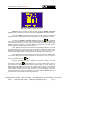
The Spectrum Analyser mode enables all the signals on a band to be viewed
on the monitor at the same time to measure analogue channels level, C/N ratio
referenced to a noise frequency defined by the user and digital channels power using
an integration method. The bandwidth of the measuring filter can be modified to
improve frequency resolution. This is an indispensable feature, as high channel density
is present on all transmission systems today. Spectrum display can be varied between
full span (the entire band) and 8 MHz terrestrial or 4 MHz satellite. In addition, there are
two markers in order to locate and list frequencies, to read signal level and frequency
difference, and the level between both.
In the satellite band, the PROLINK-2 Premium incorporates a new function for
the analysis of the narrow band signals. Il offers two additional span levels of 8 MHz
and 4 MHz with a resolution of 50 kHz.
All functionality in spectral mode has been improved adding the possibility of
extending the graphical presentation vertically. With this aim a new function has been
introduced that allows to set a variable Dynamic Range from 10-5-2 dB/div.
The PROLINK-2 Premium incorporates a specific function to test satellite
signals distribution networks. The use in combination with a IF generator allows to carry
out an easy verification of the installations before the operation beginning.
Test Equipment Depot - 800.517.8431 - 99 Washington Street Melrose, MA 02176
Page 2
FAX 781.665.0780 - TestEquipmentDepot.com
06/2004
USER’S MANUAL. PROLINK-2 Premium
The selection of sound subcarrier is automatic, depending on the standard, or
tunable between 4 and 9 MHz. When decoding TV sound it is possible to choose
between the NARROW and WIDE filter to obtain the best carrier discrimination. It
includes a NICAM decoder (with BER measurement); the possibility to commute the
channel that is delivered to the loudspeaker enables the user to check the sound stereo
and dual. Also it allows to access to the associated information to the FM transmissions
that incorporate by the radio data system (RDS).
To enhance its convenience of use, it has 99 memories to store the different
measuring configurations: name of the configuration, frequency, TV system, type of
measurement, external units powering, units of measurement and sound.
Also, the level meter incorporates the teletext function, a DiSEqC2 command
generator and permits to supply different voltages to the external unit (13 V / 15 V / 18 V
/ 24 V terrestrial TV, and 13 V / 15 V / 18 V / 13 V + 22 kHz / 15 V + 22 kHz / 18 V + 22
kHz satellite TV).
Furthermore, the instrument comes with an EUROCONNECTOR, or Scart
connector, for audio/video input/output.
It also incorporates a RS-232C interface which enables the user to connect the
instrument to a PC for data recording, remote-control of the instrument and to a printer
in order to print out the spectrum.
1.2
Specifications
CONFIGURATION FOR MEASURING LEVEL AND POWER
TUNING
Tuning modes
Resolution
Automatic search
Memory
2
Digital frequency synthesis. Continuous tuning from
45 to 862 MHz and from 900 to 2150 MHz
Frequency, Channel or Memory.
Channel plan configurable on demand
45-862 MHz:
50 kHz
900-2150 MHz: 500 kHz
50 kHz
Threshold level selectable
99 positions for measurement configurations
DiSEqCTM is a trademark of EUTELSAT.
06/2004
Page 3
English
The PROLINK-2 Premium is powered by rechargeable battery or connected to
the mains through the supplied external DC power charger.
USER’S MANUAL. PROLINK-2 Premium
RF INPUT
Impedance
Connector
Maximum signal
Maximum input voltage
DC to 100 Hz
5 MHz to 2150 MHz
LEVEL MEASUREMENT
Measurement range
Terrestrial TV & FM bands
Satellite TV band
Reading
Digital
Analogue
Measurement bandwidth
Audible indicator
Accuracy
Terrestrial bands
Satellite band
Overrange indication
75 Ω
Universal, with BNC or F adapter
130 dBµV
50 V rms (powered by the AL-103 power charger)
30 V rms (not powered by the AL-103 power charger)
130 dBµV
20 dBµV to 120 dBµV (10 µV to 1 V)
30 dBµV to 120 dBµV (31.6 µV to 1 V)
Auto-range, reading is displayed on an OSD window
Absolute value calibrated in dBµV, dBmV or dBm
Relative value through an analogue bar on the screen
230 kHz (Terrestrial band) 4 MHz (Satellite band)
(maximum band ripple 1 dB).
LV audio. A tone with pitch proportional to signal
strength.
± 1.5 dB (30-120 dBµV, 48,25-861 MHz) (22°C ± 5°C)
± 1.5 dB (40-100 dBµV, 900-2150 MHz) (22°C ± 5°C)
↑, ↓
MEASUREMENTS IN TV MODE
Terrestrial bands
Analogue channels
Level, Video-Audio ratio and Carrier-Noise ratio (Auto
and Referenced).
Digital channels
Channel power (Auto) and Carrier-Noise ratio (Auto
and Referenced) and Bit Error Rate (BER) for
COFDM modulated signals.
Satellite band
Analogue channels
Level and Carrier-Noise ratio (Auto and Referenced)
Digital channels
Channel power (Auto) and Carrier-Noise ratio (Auto
and Referenced) and Bit Error Rate (BER) for QPSK
modulated signals.
SPECTRUM ANALYSER MODE
Satellite band
Terrestrial bands
Measurement bandwidth
Terrestrial
Satellite
20 dBµV to 120 dBµV (10 µV to 1 V)
20 dBµV to 120 dBµV (10 µV to 1 V)
50 kHz, 230 kHz, 1 MHz selectable
50 kHz, 230 kHz, 4 MHz selectable
Test Equipment Depot - 800.517.8431 - 99 Washington Street Melrose, MA 02176
Page 4
FAX 781.665.0780 - TestEquipmentDepot.com
06/2004
USER’S MANUAL. PROLINK-2 Premium
Satellite
Markers
Detection
Measurements
Terrestrial bands
Analogue channels
Digital channels
Satellite band
Analogue channels
Digital channels
Full span (full band), 500, 200, 100, 50, 32, 16, 8 MHz
selectable.
Full span (full band), 500, 200, 100, 50, 32, 16, 8,
4 MHz selectable.
2 with level, frequency, level difference and frequency
difference indications.
By peak or average.
Level and Carrier-Noise ratio (Referenced)
Channel power (Integration method) and CarrierNoise ratio (Referenced).
Level and Carrier-Noise rate (Referenced)
Channel power (Integration method) and CarrierNoise ratio (Referenced).
MONITOR DISPLAY
Monitor
Colour system
TV standard
Synchronism and Burst
Spectrum mode
Sensibility
Synchronism 50/60 Hz
B & W 4 ½ inches.
PAL, SECAM and NTSC
B, G, I, D, K and L
Graphic representation over the picture
Variable span dynamic range, and reference level
40 dBµV for correct synchronism
Automatic selection according to the system
VIDEO SIGNAL
External video input
Sensibility
Video output
Scart (automatic or selectable)
1 Vpp (75Ω) positive video
Scart (75Ω)
SOUND
Input
Outputs
Demodulation
De-emphasis
Subcarrier
Variable
Fixed
Terrestrial
Satellite
06/2004
Scart
Built in speaker, Scart
AM, FM, TV and NICAM (for PAL B/G, PAL I and
SECAM L standards), selectable
50 µs
Digital frequency synthesis
From 4 to 9 MHz, 10 kHz resolution
According to the active standard: 4.50 - 5.50 - 5.74 6.00 - 6.26 - 6.50 - AM - FM - LV - OFF.
5.80 - 6.50 - 6.65 - 6.80 - 7.02 - LV - OFF
Page 5
English
Span
Terrestrial
USER’S MANUAL. PROLINK-2 Premium
CONFIGURATION FOR MEASURING DIGITAL PARAMETERS
TUNING:
COFDM:
Resolution:
QPSK:
Resolution:
from 40 to 862 MHz.
166 kHz (BW = 8 MHz) / 125 kHz (BW = 7 MHz and
6 MHz).
from 950 MHz to 2150 MHz.
500 kHz.
LEVEL RANGE
COFDM:
QPSK:
45 dBµV to 100 dBµV.
44 dBµV to 114 dBµV.
IMPEDANCE
75 Ω
MEASUREMENTS
COFDM:
Parameters:
Presentation:
QPSK:
Parameters:
Presentation:
WRONG PACKETS
BER after Viterbi. MER selectable.
CSI (Channel Status Information) selectable.
Qualitative measurement about channel quality.
Measures from 0 to 100 %. 0 % value corresponds
to maximum quality.
Numeric and level bar.
BER before Viterbi.
BER after Viterbi.
Numeric and level bar.
Number of non-correctable packets accumulated
during the measurement time, and indicates when
the fault was produced.
Identification according to levels 1.1, 1.2, 1.3 and
2.1 of TR 101 290 ETSI standard.
COFDM SIGNAL PARAMETERS
Carriers
Guard Interval
Code Rate
Modulation
Spectral inversion
Hierarchy
FEC
2k / 8k (Selected by the user).
1/4, 1/8, 1/16, 1/32 (Selected by the user).
1/2, 2/3, 3/4, 5/6, 7/8.
QPSK, 16-QAM, 64-QAM.
Selectable: ON, OFF.
Indicates hierarchy mode.
Reed-Solomon (204, 188) and Viterbi.
QPSK SIGNAL PARAMETERS
Bandwidth IQ signals
Simbol rate
variable: 10 MHz to 30 MHz in 2.5 MHz steps.
2 to 45 Mbauds.
Test Equipment Depot - 800.517.8431 - 99 Washington Street Melrose, MA 02176
Page 6
FAX 781.665.0780 - TestEquipmentDepot.com
06/2004
USER’S MANUAL. PROLINK-2 Premium
Carrier frequency
deviation
Roll-off (α) factor
of Nyquist filter
Code Rate
Spectral Inversion
TELETEXT
±0.05 x Symbol rate.
0.35.
1/2, 2/3, 3/4, 5/6, 7/8 and AUTO.
Selectable: ON, OFF
Decodes at 1.5 level
EXTERNAL UNITS POWER
SUPPLY
Terrestrial
Satellite
22 kHz signal
Voltage
Frequency
Maximum power
Through the RF input connector
External or 13/15/18/24 V
External or 13/15/18 V
Selectable
0.6 V ± 0.2 V
22 kHz ± 4 kHz
5W
DiSEqC3 GENERATOR
According to DiSEqC 1.2 standard
POWER SUPPLY
Internal
Batteries
Autonomy
Recharging time
External
Voltage
Consumption
Auto power off
7.2 V 11 Ah Li-Ion battery
> 2 hours in continuous mode.
4 hours starting of completely
(instrument off).
English
RS-232C INTERFACE
discharged
12 V
30 W
After 15 minutes without operating on any control.
Deactivable.
OPERATING ENVIRONMENTAL CONDITIONS
Up to 2000 m
Altitude
From 5 to 40 °C (automatic disconnection by
Temperature range
excess of temperature)
80 % (up to 31°C),
Max. relative humidity
decreasing lineally up to 50% at 40 °C.
MECHANICAL FEATURES
Dimensions
Weight
3
294 (W) x 100 (H) x 274 (D) mm (without holster)
5 kg
DiSEqCTM is a trademark of EUTELSAT.
06/2004
Page 7
USER’S MANUAL. PROLINK-2 Premium
INCLUDED ACCESSORIES
1x CB-047 (or equivalent)
1x AD-055
1x AD-056
1x AD-057
1x AL-103
1x DC-261
1x CA-005
Rechargeable Li+ battery 7.2 V, 11 Ah
"F"/F-BNC/F adapter
"F"/F-"DIN"/F adapter
"F"/F-"F"/F adapter
External DC charger
Carrying bag
Mains cord
OPTIONAL ACCESSORIES
CI-23
RM-104
RM-204
RM-304
Portable printer
Remote control software
Monitoring and alarm software
Monitoring and alarm system via SMS
Test Equipment Depot - 800.517.8431 - 99 Washington Street Melrose, MA 02176
Page 8
FAX 781.665.0780 - TestEquipmentDepot.com
06/2004
USER’S MANUAL. PROLINK-2 Premium
2 SAFETY RULES
2.1
General safety rules
*
Use this equipment connected only to systems with their negative of
measurement connected to ground potential.
*
The AL-103 external DC charger is a Class I equipment, for safety reasons plug it
to a supply line with the corresponding ground terminal.
*
This equipment can be used in Overvoltage Category II installations and
Pollution Degree 2 environments.
External DC charger can be used in Overvoltage Category II, installation and
Pollution Degree 1 environments.
*
When using some of the following accessories use only the specified ones to
ensure safety.
English
Rechargeable battery
External DC charger
*
Observe all specified ratings both of supply and measurement.
*
Remember that voltages higher than 60 V DC or 30 V AC rms are dangerous.
*
Use this instrument under the specified environmental conditions.
*
The user is only authorized to carry out the following maintenance operations:
Battery replacement
On the Maintenance paragraph the proper instructions are given.
Any other change on the equipment should be carried out by qualified
personnel.
*
When using the power adaptor, the negative of measurement is at ground
potential.
*
Do not obstruct the ventilation system of the instrument.
*
Use for the signal inputs/outputs, specially when working with high levels,
appropriate low radiation cables.
06/2004
Page 9
USER’S MANUAL. PROLINK-2 Premium
*
Follow the cleaning instructions described in the Maintenance paragraph.
*
Symbols related with safety:
DIRECT CURRENT
ALTERNATING CURRENT
DIRECT AND ALTERNATING
GROUND TERMINAL
PROTECTIVE CONDUCTOR
FRAME TERMINAL
EQUIPOTENTIALITY
ON (Supply)
OFF (Supply)
DOUBLE INSULATION
(Class II Protection)
CAUTION
(Risk of electric shock)
CAUTION REFER TO MANUAL
FUSE
Test Equipment Depot - 800.517.8431 - 99 Washington Street Melrose, MA 02176
Page 10
FAX 781.665.0780 - TestEquipmentDepot.com
06/2004
USER’S MANUAL. PROLINK-2 Premium
2.2
Descriptive Examples of Over-Voltage Categories
Low voltage installations isolated from the mains
Cat II
Portable domestic installations
Cat III
Fixed domestic installations
Cat IV
Industrial installations
English
Cat I
06/2004
Page 11
USER’S MANUAL. PROLINK-2 Premium
3 INSTALLATION
3.1
Power Supply
The PROLINK-2 Premium is a portable instrument powered by one 7.2 V - 11
Ah Li-Ion battery. There is also an external DC charger provided for mains connection
and battery charging.
3.1.1 Operation using the External DC Charger
Connect the external DC charger to EXT. SUPPLY [38] on the PROLINK-2
Premium side panel. Connect the DC charger to the mains. Then, press the
[1]. The level meter is now in operation and
PROLINK-2 Premium on/off key
the battery is slowly charged. When the instrument is connected to the mains, the
CHARGER indicator [7] remains lit.
For the device to operate on the battery, disconnect the power cable and press
the on/off key
[1]. The fully charged battery can power the equipment for more
than 2 hour non-stop.
If battery is very weak, the battery cut-off circuit will prevent the device from
functioning at the same time the beeper will be heard. In such a situation battery must
be recharged immediately.
Before taking any measurements, you have to check the charge state of the
battery by checking the battery charge level indicator BATTERY [8] on the front panel,
or Battery & Lnb function on the TV mode functions menu (see section '4.9.2.3
Batteries and External Units Power Supply').
The BATTERY [8] led indicates, whenever the equipment is off and connected
to the external DC charger, in a qualitative manner the battery charge condition. For
battery charge levels close to 100% it remains lit in green colour; for charge level higher
to 50% it remains amber and it appears in red to indicate the empty battery condition.
When the instrument indicates a Low Battery (led lit in red colour) the battery must be
charged immediately. When the low battery level is reached, the monitor momentarily
displays the message VERY LOW BATTERY and the beeper sounds.
Test Equipment Depot - 800.517.8431 - 99 Washington Street Melrose, MA 02176
06/2004
FAX 781.665.0780 - TestEquipmentDepot.com
Page 13
Test Equipment Depot - 800.517.8431 - 99 Washington Street Melrose, MA 02176
FAX 781.665.0780 - TestEquipmentDepot.com
English
3.1.2 Operation using the Battery
USER’S MANUAL. PROLINK-2 Premium
3.1.2.1
Battery Charging
To fully charge the battery, connect the instrument to the external DC charger
[1]. The length of time it takes to recharge it
without pressing the on/off key
depends on the condition of the battery. If they are very low the recharging period is
about 4 hours. The CHARGER [7] indicator should remain lit in amber colour.
When the battery charging process is completed with the instrument off, the fan
stops.
IMPORTANT
The instrument battery needs to be kept charged between 30% and 50% of its capacity
when not in use. The battery needs to be fully charged for best results. A fully charged
battery suffers temperature-related discharge. For example, at a room temperature of
20 °C, it can lose up to 10% of its charge over 12 months.
3.2
Installation and Start-up
The PROLINK-2 Premium level meter is designed for use as a portable device.
[1] key is pressed, the instrument is in the automatic power-off
When the
mode; that is, the device is automatically disconnected fifteen minutes after the last time
a key has been pressed. When turning on the unit, automatic power-off mode may be
[1] key until you hear two acoustic indications,
deactivated by holding down the
later "MANUAL POWER" message will appear on the lower side of the monitor. When
the device is operating, it is also possible to select the manual power-off mode by
means of the Manual power function of the TV functions menu.
Page 14
06/2004
USER’S MANUAL. PROLINK-2 Premium
4 OPERATING INSTRUCTIONS
4.1
Description of the Controls and Elements
English
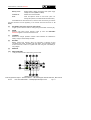
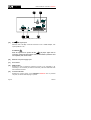
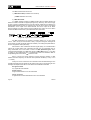
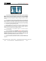
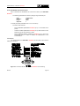
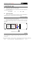
Front panel
Figure 1.- Front panel
[1]
On / Off key. This turns on the instrument, and the user can select either
manual or automatic power-off.
[2]
OSD key. Enables the measurement information format displayed on-screen in
TV mode (level measurement) to be selected.
It allows also to visualize the TV image corresponding to the input digital signal.
Activation / deactivation of teletext Zoom function.
[3]
Activation of VOLUME, CONTRAST, BRIGHTNESS control menus.
[4]
Rotary selector-button. This has many different functions: tuning control,
moving between the various on-screen menus and sub-menus, and validation
of the different options.
Test Equipment Depot - 800.517.8431 - 99 Washington Street Melrose, MA 02176
06/2004
FAX 781.665.0780 - TestEquipmentDepot.com
Page 15
USER’S MANUAL. PROLINK-2 Premium
Tuning purposes: turning it clockwise frequency increases while turning it
anticlockwise frequency decreases.
To shift along the on-screen menus: turning it clockwise active option moves
downwards while turning it anticlockwise active option moves upwards.
In TV mode, press the rotary selector-button to display the first sub-menu
containing different functions, some are dependent on the band and the
standard:
Band switching
Permits to change from terrestrial (45-862 MHz) to
satellite band (900-2150 MHz) and vice versa.
System & Standard Selects the colour system (PAL or SECAM) and the TV
standard (B/G, D/K, I, L, or Digital).
Battery & Lnb
Displays battery voltage and external units power supply
voltage and current (V Ext and I Ext).
Channel set
Selects active channels table.
Channel BW
(Satellite band or digital channels). Defines channel
bandwidth. Indispensable for measuring digital channels
and satellite band channel C/N.
Teletext
Sets teletext information.
DiSEqC
(Only satellite channels). Defines a sequence of DiSEqC
commands and permits to send them.
Reference noise
(Only in C/N Reference noise mode). Defines the
frequency where measure the noise level.
Press Next for the second sub-menu:
Page 16
Input Video
Enables Scart commutation signals to be activated,
deactivated or set to automatic/subordinate mode.
C/N setup
Defines the C/N measuring method between Auto or
Referenced.
Nicam channel
(Only analogue channels). This selects the NICAM sound
channel that is sent to the loudspeaker.
Search level
Selects the threshold level of the automatic station search
function.
Lnb local osc
(Only satellite band). It defines the frequency of the local
oscillator (L.O.) of the LNB.
Video polarity
(Only satellite band, analogue channels). This selects the
polarisation of the video carrier.
Sat IF Test
(Only satellite band, analogue channels). This selects the
function for testing satellite distribution networks.
06/2004
USER’S MANUAL. PROLINK-2 Premium
Press Previous for the first sub-menu or Next to access the third one:
Units
Selects the measuring units: dBµV, dBmV or dBm.
Manual power
Sets power-off as Manual or Automatic.
Language
Selects the language between DEUTSCH, ENGLISH,
ESPAÑOL, FRANÇAIS, and ITALIANO. Should you have
accidentally chosen the wrong language, you can return
automatically to the language menu by means the reset
process.
Beep
Activates (ON) / deactivates (OFF) the beeper.
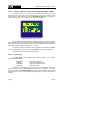
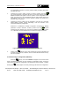
Initial screen
It shows a logo of the manufacturer as well as basic
information about the instrument description (version,
manufacturer and model).
Equipment info.
Displays information on the instrument: serial number,
version of control software, included set-up, etc.
Exit
Exits from the function menu.
IMPORTANT REMARK
In case of erroneous selection of a language, the user must follow the following
steps to accede again to the language selection menu (Language, Idioma, Sprache,
Lingua o Langue):
English
Finally, press Previous for the second sub-menu or Exit to quit the function
menu.
From the TV mode, press the rotary selector, it will appear the first sub-menu of
functions (Functions, Funciones, Funktionen, Funzioni, Fonctions), turn the rotary
selector to move the cursor to the position (Next, Siguiente, Nächst, Seguente or
Suivant) and press it to accede again to the second sub-menu. Repeat the operation
to accede to the third sub-menu. Finally, move the cursor to the fourth line of the submenu and press the rotary selector to accede to the language selection menu.
Also you can access to the language selection menu activating the reset process,
for it the reset button [38] must be pressed when the instrument is off.
In Spectrum Analyser mode, the first sub-menu displays the following
functions:
Band switching
Permits to switch from terrestrial (45-862 MHz) to satellite
band (900-2150 MHz) and vice versa.
Span
Defines the frequency range displayed between Full (the
entire band), 500 MHz, 200 MHz, 100 MHz, 50 MHz, 32
MHz, 16 MHz, 8 MHz and 4 MHz.
Test Equipment Depot - 800.517.8431 - 99 Washington Street Melrose, MA 02176
06/2004
FAX 781.665.0780 - TestEquipmentDepot.com
Page 17
USER’S MANUAL. PROLINK-2 Premium
Reference level
Defines the reference level between 10 and 130 dBµV in
10 dB steps.
Dynamic range
Defines a selectable dynamic range between 2, 5 and 10
dB/div.
Dual marker
(Only analogue channels, level measurement mode and
single marker mode). Enables dual markers to be shown
on the displayed spectrum.
ÎA
Marker AÎB
Marker B
Single marker
(Only in dual marker mode). Selects marker A as the
active marker (tuneable).
(Only in dual marker mode). Selects marker B as the
active marker (tuneable).
(Only in dual marker mode). Activates the single marker
on the displayed spectrum.
ÎRef. Noise (Only
Carrier
Ref. Noise
in C/N measurements). Permits to define the
frequency where noise level will be measured (see Ref.
Noise Carrier function).
Î
ÎCarrier (Only when measuring C/N Referenced and after defining
the CarrierÎRef. Noise). Permits to change the tuning
frequency by means of the rotary selector.
Î
Î
Marker Channel BW (Only in Channel Power measurements). Permits to
define channel bandwidth (see Channel BW Marker
function).
Î
Î
Channel BW Marker (Only when measuring Channel power and after defining
the Marker Channel BW). Permits to change the tuning
frequency by means of the rotary selector.
Sweep
Offers a choice of spectrum mode sweep rates: Fast (fast
sweep, low accuracy), High Resolution (slow sweep, high
accuracy) and Antenna Alignment (tool for faster sweep
antenna alignment without numeric data representation).
Measure bandwidth Selects the bandwidth of the spectrum measuring filter
from among:
Terrestrial channels:
Satellite channels:
50 kHz, 230 kHz or 1 MHz.
50 kHz, 230 kHz or 4 MHz.
Acquisition mode
Offers three acquisition modes: Maximum Hold, Minimum
Hold and Continuous (default).
Detection mode
Offers two detection modes: Average and Peak (default).
DiSEqC
(Only satellite channels). Defines a sequence of DiSEqC
commands and permits to send them.
System & Standard Selects the colour system (PAL or SECAM) and the TV
standard (B/G, D/K, I, L or Digital).
Page 18
06/2004
USER’S MANUAL. PROLINK-2 Premium
Battery & Lnb
Displays battery voltage and external units power supply
voltage and current (V Ext and I Ext).
Channel set
Selects active channels table.
Print
Prints the spectrum shown on the screen. (See ‘4.14
Printing the Spectrum, the Measurement and Memories’).
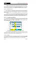
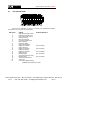
[5]
EXT VIDEO. Video signal presence light indicator
It lights up when video on screen is coming through the SCART connector [39].
[6]
DRAIN
External units power supply indicator. Lights up when the PROLINK-2
Premium supplies a current to the external unit.
[7]
CHARGER
External DC charger operation indicator. When batteries are installed the
battery charger is automatically activated.
[8]
BATTERY
Battery charge level indicator. When the instrument is switched off and
connected to the mains, the battery has three states: red if the battery charge
level is below 50%, amber if it is greater than 50% and green if the battery is
fully charged.
[9]
MONITOR
[10]
MAIN KEYBOARD
12 keys to select functions and entering numeric data.
Figure 2.- Main keyboard
English
Press Next for the second sub-menu, and from there to the third (you will see
the same functions as those appearing in the second and third sub-menus in TV
mode).
Test Equipment Depot - 800.517.8431 - 99 Washington Street Melrose, MA 02176
06/2004
FAX 781.665.0780 - TestEquipmentDepot.com
Page 19
USER’S MANUAL. PROLINK-2 Premium
[20]
DIGITAL - ANALOGUE MODE SWITCHING
Switches between analogue and digital mode.
Key number 0 to enter numeric data.
[21]
SPECTRUM/TV MODE SWITCHING
Enables switching between the TV and the Spectrum Analyser operation mode,
and back again.
Key number 1 to enter numeric data.
[22]
MEASURE
Enables the type of measurement to be selected. The types of measurements
available depend on the band, the standard, the options included and the
operating mode.
Key number 2 to enter numeric data.
[23]
TV MODE
Selects the information displayed on-screen in TV operation mode (LV
measurement).
Key number 3 to enter numeric data.
[24]
SEARCH
This is the function for automatic station search. Starting at the present
frequency or channel, it searches until finds a station with an adequate level.
The threshold level (search level) can be defined by means of the TV mode
functions menu between 30 and 99 dBµV.
Key number 4 to enter numeric data.
[25]
STORE/RECALL
This key enables the measurement configuration to be stored/recalled. Each
configuration has the following information: name assigned to memory, memory
number, Channel or frequency (Freq), TV system (TV Sys), measurement
mode (Meas), external units power supply (V Lnb), measurement units (Units)
and Sound. The memory can store up to 99 measurement configurations
(numbered from 1 to 99).
Key number 5 to enter numeric data.
Page 20
06/2004
USER’S MANUAL. PROLINK-2 Premium
SOUND
This selects the type of sound. The options available in each case depend on
the band and the standard selected (see section 4.11 Selecting the Sound
Mode).
Key number 6 to enter numeric data.
[27]
EXTERNAL UNITS POWER SUPPLY
Enables selecting the power supply to the external units. Available voltages are:
External, 13 V, 15 V, 18 V and 24 V for the terrestrial band and External, 13 V,
15 V, 18 V, 13 V + 22 kHz, 15 V + 22 kHz and 18 V + 22 kHz for the satellite
band.
Key number 7 to enter numeric data.
[28]
DIRECT ACCESS KEY
Direct access key which can be assigned to any function on any menu.
Key number 8 to enter numeric data.
[29]
DIRECT ACCESS KEY
Direct access key which can be assigned to any function on any menu.
Key number 9 to enter numeric data.
[30]
TUNING BY CHANNEL OR FREQUENCY
Switches tuning mode between channel and frequency. In channel mode the
tuning frequency is defined by the active channels table (CCIR, OIRT, ...). See
channel-frequency tables in Appendix A.
Decimal point key to enter numeric data.
[31]
MANUAL FREQUENCY SELECTION / SHIFT
Enables the desired frequency to be directly tuned using the numeric keyboard.
Also acts as a SHIFT key for moving across different fields on some screens.
English
[26]
Test Equipment Depot - 800.517.8431 - 99 Washington Street Melrose, MA 02176
06/2004
FAX 781.665.0780 - TestEquipmentDepot.com
Page 21
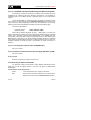
USER’S MANUAL. PROLINK-2 Premium
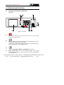
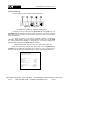
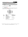
Figure 3.- Side panel connections.
[35]
RF
RF signal input.
Maximum level 130 dBµV. Universal connector for F/F or F/BNC adapter, with
input impedance of 75 Ω.
ATTENTION
Note the importance to protect the RF
[37] input signal with an
accessory to block the AC voltages used in CATV cables (needed to feed
the amplifiers) and remote mode.
[36]
External 12 V power supply input
[37]
Scart socket
[38]
RESET button
Enables the user to restart the instrument if there is any irregularity in its
functioning. If it is necessary to reset the instrument, press the reset button with
the instrument turned off.
[39]
Connector RS-232C
Enables the remote control of the PROLINK-2 Premium from a personal
computer, as well as data dumping to a printer.
Page 22
06/2004
USER’S MANUAL. PROLINK-2 Premium
4.2
Adjustment of Volume and Monitor Parameters
Repeatedly pressing key
[3] sequentially activates the VOLUME,
CONTRAST and BRIGHTNESS. On activation of a menu for a specific parameter the
screen displays a horizontal bar whose length is proportional to the parameter level, to
modify this value simply turn the rotary selector [4]. To exit the menu and validate the
new value press the rotary selector [4].
4.3
Selecting the Operation Mode: TV / Spectrum Analyser
The PROLINK-2 Premium has two basic operation modes: TV and Spectrum
Analyser. To switch from one operation mode to the other press key
[21].
In the Spectrum Analyser operation mode the screen displays the spectrum of
the active band (terrestrial or satellite). The span, the reference level and the measuring
filter bandwidth are variable as will be shown in paragraph '4.10 Spectrum Analyser
Operation Mode'.
4.4
RF Band Selection: 45-862 MHz / 900-2150 MHz
English
In the TV operation mode the demodulated television signal is shown
on-screen; this is the default operation mode, various functions can be selected, as
shown in the following paragraphs.
Tuning is continuous between 45 and 862 MHz (terrestrial band) and between
900 and 2150 MHz (satellite band). There are three ways of changing the active band:
1)
Press the rotary selector [4] to accede to the functions menu, if necessary
turn it to select the Band switching function and then press it again. The
RF band will be switched automatically.
2)
[31] and select a frequency on the new band using the
Press key
numeric keyboard. The fifth digit and second decimal act as confirmation.
For example, if the active band is the 900 to 2150 MHz band and you
wish to tune the 49 MHz frequency (belonging to the 5/45 to 862 MHz
band), press key
numeric keyboard.
[31] and then enter 49.00 or 049.0 using the
Alternatively, the rotary selector [4] can be pressed to indicate the end of
the numerical entry.
3)
Recall a memory with a tuning frequency belonging to the band you wish
to access. (See section '4.12 Measurement Configuration Memories').
Test Equipment Depot - 800.517.8431 - 99 Washington Street Melrose, MA 02176
06/2004
FAX 781.665.0780 - TestEquipmentDepot.com
Page 23
USER’S MANUAL. PROLINK-2 Premium
4.5
Channel Tuning / Frequency Tuning
Pressing key
[30] the PROLINK-2 Premium switches from frequency
tuning to channel tuning and back again.
In channel tuning mode turning the rotary selector [4] sequentially tunes the
channels defined in the active channels table (see the Channel set function in the TV
mode functions menu, section '4.9.2.7 Selecting the Channels Table'). When turning it
clockwise frequency increases while turning it anticlockwise frequency decreases.
In frequency tuning mode there are two ways of tuning:
1. Turning the rotary selector [4].
Turning the rotary selector [4] selects the desired frequency (tuning is
continuous from 45 to 862 MHz and from 900 to 2150 MHz). When turning it
clockwise frequency increases while turning it anticlockwise frequency
decreases.
2. Using the keyboard.
(the frequency listing will disappear), next enter the
Press key [31]
frequency value in MHz using the numeric keyboard, the fifth digit, to press
the rotary selector [4] or the second decimal act as confirmation. The
PROLINK-2 Premium will calculate the tuneable frequency closest to the
entered value and then display it on-screen.
4.6
Automatic Transmission Search
In the TV mode, by pressing the
[24] key search starts at the present
frequency or channel until it finds a transmission with a level higher than the search
level. The threshold level is defined by means of the Search level function of the TV
mode functions menu (see paragraph '4.9.2.16 Search Level'.).
The Search function halts the search process when the end of the present band
is reached, if it is in frequency mode, or when a key is pressed. In channel mode, the
search process is halted when the last channel of the group selected is reached (see
Appendix A). The sound is deactivated during the search process.
4.7
Selecting Analogue / Digital Mode
Measuring the characteristics of a channel depends, in the first place, on the
type of modulation: analogue or digital.
[20] to switch between analogue and digital channels. When
Use key
switching to a new modulation, the PROLINK-2 Premium activates the last
measurement configuration used for that modulation.
Page 24
06/2004
USER’S MANUAL. PROLINK-2 Premium
Also it is possible to switch between analogue and digital modes by means of
System & Standard from function menu.
4.8
External Units Power Supply (EXT. SUPPLY)
The PROLINK-2 Premium can supply the voltage needed to power the external
units (antenna preamplifiers, in the case of terrestrial TV, LNB in the case of satellite
TV, or IF simulators).
Maximum input levels
DC to 100 Hz
50 V rms (powered by the AL-103 power charger)
30 V rms (not powered by the AL-103 power charger)
45 MHz to 2150 MHz 130 dBµV
To select the supply voltage of the external units, press key
[27], and the
screen will display a functions menu labelled EXT. SUPPLY listing the choice of
voltages (which will depend on the band being used). Turn the rotary selector [4] to the
desired voltage and press to activate it.
Band
Powering voltages
SATELLITE
External
13 V
15 V
18 V
13 V + 22 kHz
15 V + 22 kHz
18 V + 22 kHz
External
13 V
15 V
18 V
24 V
TERRESTRIAL
MATV
English
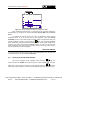
The following table shows the choice of supply voltages:
Table 1.- External units powering voltages.
In the External power supply mode the unit powering the amplifiers before the
antenna (terrestrial television) or the satellite TV receiver (house-hold or community)
also powers the external units.
The DRAIN [6] indicator lights when current is flowing to the external unit. If any
kind of problem occurs (e.g., a short circuit), an error message appears on the monitor
('SUPPLY SHORT'), the acoustic indicator will be heard and the instrument will cease
to supply power. The PROLINK-2 Premium does not return to its normal operating
state until the problem has been solved.
Test Equipment Depot - 800.517.8431 - 99 Washington Street Melrose, MA 02176
06/2004
FAX 781.665.0780 - TestEquipmentDepot.com
Page 25
USER’S MANUAL. PROLINK-2 Premium
4.9
TV Operating Mode
4.9.1 Selecting the Measurement Mode (MEASURE)
The types of measurements available depend on the band, the standard and
the operating mode.
Terrestrial band - Analogue channels:
Level
Level measurement of the currently tuned carrier.
Video / Audio
Video carrier to audio carrier level ratio.
C/N
Ratio between the modulated signal power and the
equivalent noise power fora same bandwidth. There are two
methods to make this measurement (selectable through the
C/N setup function):
Auto: In-channel measurement. Noise level is measured at
a frequency where modulation contents is minimum. After a
small period of time, minimum measured level corresponds
to noise level.
Referenced: The user defines the frequency where noise
level will be measured (by means of the Reference noise
function). This frequency will be used to measure noise
level for all channels.
Terrestrial band - Digital channels:
Channel power
Automatic method: channel power is measured assuming
that power spectral density is uniform throughout channel
bandwidth. To measure it correctly it is indispensable to
define the Channel BW.
C/N
Two methods selectable through the C/N setup function:
Auto: Out-channel measurement. Noise level is measured
at fnoise= ftuning - ½*Channel BW. To measure it correctly
digital channel must be tuned at its central frequency.
Referenced: The user defines the frequency where noise
level will be measured (by means of the Reference noise
function). This frequency will be used to measure noise
level for all channels.
BER (COFDM)
Page 26
Obtains the error rate for the signal found in the tuned
channel. After processing for a few seconds, the screen on
the PROLINK-2 Premium shows the type of modulation,
the CSI (Channel Status Information) or the MER
measurement (modulation error ratio) selectable by means
of the option COFDM Setup from functions menu, as well
as the BER (error rate) for the digital signal after error
correction (BER after Viterbi), the latter two are shown in
06/2004
USER’S MANUAL. PROLINK-2 Premium
analogue form as a bar graph. The instrument also shows
the channel or frequency with the corresponding deviation,
the number of wrong packets received during the
measurement time (W.P.) and information on the type of
digital Multiplex detected (MPEG2, Network, Provider,
Bouquet) which appears cyclically on the screen.
Satellite band - Analogue channels:
Level
Level measurement of the currently tuned carrier.
C/N
Ratio between the modulated signal and the equivalent
noise power for a same bandwidth (Auto or Referenced).
Channel power
Automatic method.
C/N
Ratio between the modulated and the equivalent noise
power for a same bandwidth (Auto or Referenced).
BER (QPSK)
Obtains the error rate for the signal found in the tuned
channel. After processing for a few seconds, the screen on
the PROLINK-2 Premium shows the type of modulation,
the BER (error rate) for the digital signal before error
correction (BER before FEC) or the MER measurement
(modulation error ratio) selectable by means of the option
QPSK Setup from functions menu, as well as the BER
after error correction (BER after Viterbi), the latter two are
shown in analogue form as a bar graph. The instrument
also shows the channel or frequency with the
corresponding deviation and information on the type of
digital Multiplex detected (MPEG2, Network, Provider,
Bouquet) which appears cyclically on the screen.
To change the measurement mode press key
[22]. The screen will display
a menu with the measurement modes which can be selected.
Test Equipment Depot - 800.517.8431 - 99 Washington Street Melrose, MA 02176
06/2004
FAX 781.665.0780 - TestEquipmentDepot.com
Page 27
English
Satellite band - Digital channels
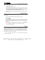
USER’S MANUAL. PROLINK-2 Premium
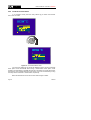
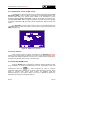
Figure 4.- Measuring mode selection (satellite band, analogue channels).
To select a measurement mode turn the rotary selector [4] until it is marked
[22] to
(e.g., Level in the previous figure), then press the rotary selector [4] or key
activate the selected measurement mode.
4.9.1.1
Measuring the Video Carrier Level (Level)
If you select the Level measurement mode, the screen shows a window with
the signal level, when selected with the OSD key
[2] (see next section).
WARNING
If a sudden signal level increase is produced at the RF input, and it is beyond the total
signal levels of:
Terrestrial band:
Satellite band:
95 dBµV
105 dBµV
the tuning circuit may become out of control, giving as a result wrong level
measurements.
If this situation occurs, disconnect the input signal, change to Spectrum Analyser
mode and select a Reference Level of 130 dBµV. Then connect the signal again
and modify the Reference Level according to present signals.
Similar effects can be observed when at the RF input appears an important number of
carriers with a high level. To be able to determinate the equivalent level of a carrier
group (with similar levels) at the RF input, it is possible to use the expression:
Page 28
06/2004
USER’S MANUAL. PROLINK-2 Premium
Lt=L + 10 log N
Lt: equivalent total level
L: average level of the carriers group
N: number of carriers
So, if there are ten carriers with a level around 90 dBµV, their equivalent level will be:
90 dBµV + 10 log 10 = 100 dBµV
Observe that in this case, loss of tuning by overload of the RF input may occur besides
other effects such as tuner saturation and generation of intermodulation products that
may mask the spectrum visualization.
4.9.1.1.1
Changing the measurement information format
In TV operation mode, the measurement information format to be displayed
[2]. Three possibilities are offered, selected
-
TV image with a window in the lower part of the screen displaying the signal
level and frequency/channel.
-
TV image with a window displaying information on the name assigned to
memory, power supply to external units, sound, colour system, TV
standard, level and frequency/channel.
-
TV image only.
4.9.1.1.2
Selecting TV Mode: TV, LV, SY (TV MODE)
In addition to operating as a television set, the monitor of the PROLINK-2
Premium can act as an analogue level indicator, and can display the line synchronising
pulse just as it would appear on a screen of an oscilloscope.
To change the TV mode press key
[23], and the following screen will
appear:
Test Equipment Depot - 800.517.8431 - 99 Washington Street Melrose, MA 02176
06/2004
FAX 781.665.0780 - TestEquipmentDepot.com
Page 29
English
on-screen is selected by pressing key
cyclically:
USER’S MANUAL. PROLINK-2 Premium
Figure 5.- TV mode selection.
Turn the rotary selector [4] to choose the information you want to be displayed
on-screen. Press the rotary selector [4] or key
mode.
[23] to activate the selected display
The operation modes available are:
TV:
Monitor operating as a conventional television set.
TV+LV:
Monitor operating as a conventional television set, with a level
indicator on the upper part of the screen (the analogue bar).
TV+LV+SY: Monitor operating as a conventional television set, with a level
indicator and the line synchronizing pulse displayed on the
screen.
LV:
Signal level indication on the upper part of the screen (analogue
bar).
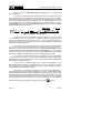
Operation in TV+LV+SY Mode
This function permits to display the line synchronising pulse corresponding to a
tuned signal on the monitor.
To view the synchronisation pulse press key
[4] to TV + LV + SY mode, and then press key
[23], turn the rotary selector
[23] or the rotary selector [4] again.
The monitor is divided into three sections. In the top section an analogue bar
appears which indicates the level of the signal received (59 dBµV in figure 6 example).
On the left side the line synchronising pulse is represented as it would appear on the
screen of an oscilloscope. On the lower side the TV picture is shown.
Page 30
06/2004
USER’S MANUAL. PROLINK-2 Premium
Figure 6.- Line synchoronism + level + TV (TV+LV+SYNC)
Starting from the line synchronism representation, it is possible to perform a
qualitative analysis of the TV picture delivered to the end user.
In the Video/Audio measurement mode, the screen displays the following
information:
English
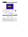
4.9.1.2 Measuring the Video / Audio Ratio (V/A)
Figure 7.- Video/Audio rate measurement
In addition to the video carrier / audio carrier level ratio (15.0 dB in previous
figure) this also shows the frequency or channel, depending on the tuning mode
selected, and the level of the video carrier and audio carrier.
Test Equipment Depot - 800.517.8431 - 99 Washington Street Melrose, MA 02176
06/2004
FAX 781.665.0780 - TestEquipmentDepot.com
Page 31
USER’S MANUAL. PROLINK-2 Premium
4.9.1.3
Measuring the Carrier / Noise Ratio (C/N)
The PROLINK-2 Premium offers two ways to make this measurement:
Auto:
The PROLINK-2 Premium defines the frequency where
noise level is measured automatically.
Reference noise:
The user defines the frequency where noise level is
measured (by means of the Reference noise function).
This frequency will be used to measure noise level for all
channels.
To select the measuring method activate the TV mode functions menu by
pressing the rotary selector [4], then turn it to select C/N setup function and finally press
it again. The monitor will show a screen displaying two possibilities: C/N (Auto) and
C/N (Reference noise), then turn the rotary selector to select the desired option and
finally press it to confirm.
When selecting the C/N (Reference noise) mode it is necessary to define the
noise frequency: access the functions menu and now turn the rotary selector to select
Reference noise function and finally press it again. A screen titled REFERENCE
NOISE will be displayed showing the noise frequency in use. To change it press key
[31], the current frequency value will disappear and, using the keyboard, you will
be able to enter the new reference noise frequency in MHz and with two decimals
figures. This frequency also can be modified in the Spectrum operation mode (see
4.10.2.2. C/N (Referenced) Measurement).
The PROLINK-2 Premium carries out C/N ratio measurement in four different
ways, according to the carrier type and the band in use:
A)
Terrestrial band, analogue carrier
Carrier level is measured using a quasi-peak detector (230 kHz BW). Noise
level is measured with an average detector and corrected to refer it to channel
equivalent noise bandwidth (according to the standard in use).
B)
Terrestrial band, digital carrier
Both measurements are done with an average detector (230 kHz) and the same
corrections are introduced on them (bandwidth corrections).
C)
Satellite band, analogue carrier
Carrier level is measured using a quasi-peak detector (4 MHz BW). Noise level
is measured with an average detector (4 MHz) and corrected to refer it to
channel bandwidth.
D)
Satellite band, digital carrier
Equivalent to case B but now using the 4 MHz BW filter.
Page 32
06/2004
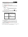
USER’S MANUAL. PROLINK-2 Premium
On selecting the Carrier / Noise measurement mode the screen displays the
following information:
C /N (AU TO )
20.1 dB
V ID E O C A R R IE R :
FREQ UENCY
L E VE L
N O IS E :
L E VE L
CH ANN EL BW
= 134 5.5 M Hz
= 64 .1 dBuV
=
=
44 .1
32 .0
dBuV
M Hz
Figure 8.- Carrier-to-noise ratio measurement (Auto mode).
When measuring channels in the satellite band or digital channels, to measure
the C/N ratio correctly, the bandwidth of the channel must be defined previously, using
the Channel BW function on the TV mode functions menu.
IMPORTANT REMARK
To measure digital channels C/N ratio in Auto mode it is indispensable to tune channel
at its central frequency.
In the case of the presence of adjacent digital channels, these could mask the noise
level measurement when operating in Auto mode. Therefore, you are recommended to
use the Referenced mode.
IMPORTANT REMARK
In the case of an analogue terrestrial signal, when C/N (Auto) mode is selected, the
PROLINK-2 Premium performs an in-channel measurement, this involves that C/N
value will take several seconds to stabilize (six seconds at the most). An arrow below
the C/N readout represents the measurement cycle and it is necessary to wait the arrow
passes twice on the same point to guarantee a correct measurement.
Test Equipment Depot - 800.517.8431 - 99 Washington Street Melrose, MA 02176
06/2004
FAX 781.665.0780 - TestEquipmentDepot.com
Page 33
English
As well as the video carrier / noise level ratio (20.1 dB in previous figure), the
frequency or channel (depending on the tuning mode selected) and the level of the
video carrier and noise level are also shown.
USER’S MANUAL. PROLINK-2 Premium
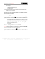
4.9.1.4
Measuring the Power of Digital Channels (Channel power)
The PROLINK-2 Premium offers two different methods to measure digital
channels power, according to the active operation mode: Automatic method in TV
mode and Integration method in Spectrum mode. The Automatic method measures
digital channel power in the measurement filter bandwidth and estimates total channel
power assuming that spectral density is uniform throughout channel bandwidth. On the
other hand, the Integration method takes into account signal spectral distribution so
measurement is more accurate but slightly slower (see 4.10.2 Selecting the
Measurements Mode). The obtained measurements using these methods may differ
some dBs, specially when the digital signal is degraded.
Figure 9.- Measuring digital power.
Page 34
06/2004
USER’S MANUAL. PROLINK-2 Premium
On selecting the CHANNEL POWER measurement mode, the screen displays
the following information:
In addition to the power of the digital channel (45.8 dBµV in previous figure) this
also shows the tuning frequency or channel, depending on the tuning mode selected,
and the parameters regarding bandwidth: Channel BW and measuring filter bandwidth
(Measure BW).
For the power measurement of a digital channel to be correct it is essential to
have previously defined the channel bandwidth using the Channel BW function, in the
TV mode functions menu (see section '4.9.2.11 Channel Bandwidth’).
4.9.1.5
BER measurement mode selection
The PROLINK-2 Premium offers three ways to measure the error rate (BER)
of digital signals depending on the type of used modulation.
To select the BER measurement mode:
1)
Select the TV operating mode. If present operating mode is the spectrum
analyser mode press key
2)
Select the terrestrial band for the measurement of COFDM modulated signals
or the satellite band for the measurement of QPSK modulated signals. Available
frequency ranges are:
COFDM signals
QPSK signals
3)
[21].
40 MHz to 862 MHz
950 MHz to 2150 MHz
Select the DIGITAL operating mode by means of the key
[20].
Test Equipment Depot - 800.517.8431 - 99 Washington Street Melrose, MA 02176
06/2004
FAX 781.665.0780 - TestEquipmentDepot.com
Page 35
English
Figure 10.- Digital channel power measurement.
USER’S MANUAL. PROLINK-2 Premium
4)
Select the BER measurement mode: to do this press key
[22] and turn
the rotary selector [4] to select the BER measuring mode, next, to activate it
press the rotary selector [4] or key
[22].
Before measuring the BER or analysing the Wrong Packets in the Transport
Stream MPEG-2 / DVB is necessary to define some parameters concerning the digital
signal, which are described in the following section (see section '4.9.1.5.1. Measuring
BER of QAM Digital Channels (QAM)’). To see its present value or to modify it, being in
the BER measuring screen, press the rotary selector, it will appear a multiple-choice
menu showing the functions relative to the BER measurement on the screen.
4.9.1.5.1
Measuring BER of COFDM Digital Channels (COFDM)
Press the rotary selector to access the COFDM signals parameters that must
be defined by user and that are described below:
1)
Carriers
It defines the number of modulation carriers between 2k and 8k. To modify its
value, place the marker over the Carriers field by turning the rotary selector and
then press it: a menu will appear on the screen. Turning the rotary selector select
the desired value for the Carriers parameter and finally press it again to validate.
2)
Guard interval
The Guard Interval parameter corresponds to the time dead between symbols,
its purpose is to permit a correct detection in multi-path situations. This
parameter is defined according to the symbol length: 1/4, 1/8, 1/16, 1/32. To
modify its value, by turning the rotary selector, place the marker over the Guard
Interval field and then press it : a menu with the available values will appear.
Turning the rotary selector select the desired value and finally press it to
validate. If Guard Interval parameter is not known it is possible to assign the
Auto option for its automatic detection.
3)
Channel BW (channel bandwidth)
Enables the channel bandwidth to be selected between 8 MHz, 7 MHz and 6
MHz. The selection of this parameter is essential for the correct operation of the
tuner, as it affects the frequency separation of the carriers.
4)
Spectral Inv. (spectral inversion)
This option enables spectral inversion to be applied to the input signal, though in
the majority of cases it should be in the OFF position (not inversion).
5)
Attenuator
It permits to select attenuation between 0 and 30 dB. It is advisable to activate
the 30 dB attenuator under that measurement conditions where the signal level
is near to the maximum input level (approximately starting from 20 dB under the
maximum level) and it is possible that the tuner becomes saturated. Under nosaturation conditions, when increasing the attenuation value the BER measure
must to maintain or to increase (insufficient signal level) but never to decrease.
Page 36
06/2004
USER’S MANUAL. PROLINK-2 Premium
This configuration menu shows, besides the user definable COFDM signal
parameters, the value of the rest of COFDM signal parameters detected automatically:
Code Rate
Also known as Viterbi ratio, defines the ratio between the data bits
number and the total number of bits transmitted (the difference
corresponds to the number of control bits for the error detection and
recovery).
Modulations
Carriers modulation. It also defines the system noise immunity.
(QPSK, 16-QAM and 64-QAM).
Hierarchy
The DVB-T norm contemplates the possibility to make a TDT
transmission with hierarchical levels, it is to say a simultaneous
transmission of the same program with different image qualities and
noise protection levels, in order the receiver can exchange to a signal
of smaller quality when the reception conditions are not optimal.
English
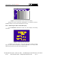
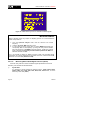
Once you have defined the COFDM signal parameters, it will be possible to
measure the BER. When the BER measuring mode is selected, the monitor will show a
picture like the following:
Figure 11.- BER measuring screen for COFDM-modulated signals
Two measures are shown :
1)
CSI: Channel status information
(or MER: Modulation error ratio)
2)
BER after Viterbi
The CSI measure (Channel Status Information) is a qualitative measure about
channel state, between 0 and 100%. The optimum value corresponds to 0%. This
measure permits to look for the best situation even in those measuring conditions where
the measured BER is best than the minimum readout (in this way, in the example of the
-7
previous figure, the measured BER is lower that the minimum readout, 1.0x10 , but the
CSI measurement, 27%, still can be improved).
Test Equipment Depot - 800.517.8431 - 99 Washington Street Melrose, MA 02176
06/2004
FAX 781.665.0780 - TestEquipmentDepot.com
Page 37
USER’S MANUAL. PROLINK-2 Premium
Next it is shown the BER after Viterbi measurement both in numeric and
graphic bar format.
In a reception system of terrestrial digital signal, after the COFDM decoder two
error correction methods are applied. Obviously, each time we apply an error corrector
to the digital signal, the error rate changes, therefore if we measure the error rate at the
output of the COFDM demodulator, at the output of the Viterbi decoder, and at the
output of the Reed-Solomon decoder, we obtain nothing more than different error rates.
The PROLINK-2 Premium provides the BER after Viterbi and the number of Wrong
packets received after Reed- Solomon.
Figure 12.- COFDM reception system.
The BER measurement is provided in scientific notation (i.e. 3.1 E-7 means
-7
3.1x10 , that is to say 3.1 wrong bits of each 10000000) and through a graphic bar (as
its length is smaller the signal quality will be better). The analogue representation is
done on a logarithmic scale (not linear), that is to say, the bar divisions correspond to
the exponent of the measurement.
With the aim to have a reference about the signal quality, it is considered that a
system has a good quality when it decodes less than one non-correctable error for
every transmission hour. This border is known as QEF (Quasi-Error-Free) and it
-4
corresponds approximately to a BER after Viterbi of 2.0E-4 BER (2.0x10 , that is to say
2 wrong bits of each 10000). This value is marked on the measurement bar of the BER
and therefore, BER for acceptable signals must be at the left side of this mark.
In the lower line of the screen it appears the W. P. counter (Wrong Packets
counter). This counter shows the number of non-correctable packets received after
Reed-Solomon during the measuring time. This counter is automatically activated when
the unit detects an MPEG-2 signal.
If at any time, the received signal stops to satisfy the requirements of the
MPEG-2 standard, this counter will deactivate, that is to say it will keep the number of
non-correctable packets received and the measuring time, later, if an MPEG-2 signal is
received again, it will activate with no reset.
When during any measuring time interval the counter has been deactivated, in
other words the signal has not satisfied the MPEG-2 synchronism, the presentation of this
counter will alternate with another counter titled FAIL. This second counter shows the time
that the detected signal has not fulfilled the MPEG-2 standard requirements (12 seconds
in the example of the following figure) and the number of signal cuts (2 in the example of
the following figure). To reset the counter it is necessary to change any of the detection
parameters, for example tune again the signal or push twice the
Page 38
[22] key.
06/2004
USER’S MANUAL. PROLINK-2 Premium
Figure 13.- Signalling two MPEG-2 signal cuts with a total length of 12 seconds.
Finally it is shown a status line with information about the detected signal. The
possible messages that can appear and its meaning are showing the following list. The
messages are exposed from less to more fulfilment of the MPEG-2 standard:
Timing recovered
Only it is possible to recuperate the symbol time.
AFC in lock
The system automatic frequency control can identify and lock a digital
transmission (TDT) but its parameters can not be obtained. It can be due to a
transitory situation previous to the TPS identification (Transmission Parameter
Signalling) or well to a TDT transmission with an insufficient C/N ratio.
English
No signal received
No signal has been detected.
TPS in lock
The TPS (Transmission Parameter Signalling) are decoded. The TPS are
carriers (17 in the 2k system and 68 in the 8k system) modulated in DBPSK,
containing information related to the transmission, modulation and codification:
Modulation type (QPSK, 16-QAM, 64-QAM), Hierarchy, Guard Interval, Viterbi
Code Rate, Transmission mode (2k or 8k) and Number of the received frame.
MPEG-2
Correct detection of a MPEG-2 signal.
In case of detecting a DVB signal, message MPEG-2 DVB-T.
The PROLINK-2 Premium, also offers the possiblity of measuring the
modulation error ratio (MER) for COFDM signals. Once the COFDM signal parameters
have been defined, you can access to the digital mode function menu by pressing the
rotary selector [4], then turn it to select COFDM setup function and finally press it again.
The monitor will show a screen displaying two possibilities: CSI and MER, then turn the
rotary selector [4] to select the desired option and finally press it to confirm.
Test Equipment Depot - 800.517.8431 - 99 Washington Street Melrose, MA 02176
06/2004
FAX 781.665.0780 - TestEquipmentDepot.com
Page 39
USER’S MANUAL. PROLINK-2 Premium
Figure 14.- MER measuring screen for COFDM-modulated signals.
IMPORTANT REMARK
DVB-T channels tuning may require an adjusting process. It is recommended to
follow next procedure:
1.- From the spectrum analyser mode, tune the channel at its central
frequency.
2.- Switch to TV mode, BER measuring mode.
3.- If in the lower line of the screen does not appear MPEG-2 message (and
consequently BER is unacceptable), by turning the rotary selector deviate
the tuning frequency until MPEG-2 message appears. Finally tune channel
again to minimize the frequency deviation which optimizes the BER and
therefore minimize the BER.
If it is not possible to detect any MPEG-2 channel, make sure that digital signal
parameters are correctly defined and if signal level is too low, check that the 30 dB
attenuator is not activated (Attenuator 0 dB).
4.9.1.5.2
Measuring BER of QPSK Digital Channels (QPSK)
Press the rotary selector to access the QPSK signals parameters that must be
defined by user and that are described below:
1)
Page 40
Symbol Rate
It is possible to choose between the following values : 30000, 27500, 22000,
20000, 19995, 6110, 6000, 5998, 5632, 5062, 4340, 4000 kbauds, or well to
define any other value (Other).
06/2004
USER’S MANUAL. PROLINK-2 Premium
When selecting the Other option, a screen titled QPSK SYMBOL RATE will
2)
Code Rate
Also known as Viterbi ratio. It defines the ratio between the number of data bits
and actual transmission bits (the difference corresponds to the control bits for
error detection and correction).
It permits to choose between 1/2, 2/3, 3/4, 5/6, 7/8 and Auto. If Code Rate
parameter is not known it is possible to assign the Auto option.
3)
Spectral Inv.
If necessary, activate the Spectral inversion. Reception will be bad if spectral
inversion has been incorrectly selected.
4)
Attenuator
It permits to select attenuation between 0 and 30 dB. It is advisable to activate
the 30 dB attenuator under that measurement conditions where the signal level
is near to the maximum input level (approximately starting from 20 dB under the
maximum level) and it is possible that the tuner becomes saturated. Under nosaturation conditions, when increasing the attenuation value the BER measure
must to maintain or to increase (insufficient signal level) but never to decrease.
English
and
appear. This screen shows present value, to modify it press key
enter the new value through the keyboard. The unit accepts any number with 5
figures between 2000 and 35000 kbauds (fifth figure acts as validation). For
example, to select a symbol rate of 8200 kbauds it must be entered : 08200.
Once you have defined the QPSK signal parameters, it will be possible to
measure the BER. When the BER measuring mode is selected, the monitor will show a
picture like the following:
Figure 15.- BER measuring screen for QPSK modulated signals.
Test Equipment Depot - 800.517.8431 - 99 Washington Street Melrose, MA 02176
06/2004
FAX 781.665.0780 - TestEquipmentDepot.com
Page 41
USER’S MANUAL. PROLINK-2 Premium
Two BER measurements are shown:
1) BER before FEC (Forward Error Corrections)
(or MER: Modulation error ratio)
2) BER after Viterbi
In a digital reception system for satellite signals, after the QPSK decoder two
different correction methods are applied (see figure 18). Obviously, each time we apply
an error corrector to a digital signal, the error rate changes, therefore if we measure in a
digital satellite television system, for example, the error rate at the output of the QPSK
demodulator, at the output of the Viterbi decoder, and at the output of the ReedSolomon decoder, we obtain nothing more than different error rates. This is the reason
because the BER measurement is provided before FEC, after Viterbi.
Figure 16.- Digital reception system via satellite.
The BER measurement is provided in scientific notation (i.e. 2.0 E-3 means
-3
2.0x10 , that is to say two incorrect bits of every 1,000) and through an analogue bar
(as its length is smaller the signal quality will be better). The analogue representation is
done on a logarithmic scale (not linear).
With the aim to have a reference about the signal quality, it is considered that a
system has a good quality when it decodes less than one non-correctable error for
every transmission hour. This border is known as QEF (Quasi-Error-Free) and it
-4
corresponds approximately to a BER after Viterbi of 2.0E-4 BER (2.0x10 ). This value
is marked on the measurement bar of the BER after Viterbi and therefore, BER for
acceptable signals must be at the left side of this mark.
Next it is shown the tuning frequency and the frequency deviation in MHz
between the tuned frequency and the one which optimizes the BER (i.e. Freq: 1777.0
+ 1.2 MHz).
Finally it is shown a status line with information about the detected signal. The
possible messages that can appear and its meaning are shown in the following list. The
messages are exposed from less to more fulfilment of the MPEG-2 standard:
No signal received
Any signal has been detected.
Signal received
A signal is detected but it can not be decoded.
Carrier recovered
A digital carrier has been detected but it can not be decoded.
Page 42
06/2004
USER’S MANUAL. PROLINK-2 Premium
Viterbi synchronized
A digital carrier has been detected and the Viterbi algorithm is synchronized, but
too many frames arrive with non correctable errors. It is not possible to quantify
the BER.
MPEG-2
Correct detection of a MPEG-2 signal.
In case of detecting a DVB signal, message MPEG-2 DVB-S.
English
The PROLINK-2 Premium, also offers the possiblity of measuring the
modulation error ratio (MER) for QPSK signals. Once the QPSK signal parameters have
been defined, you can access to the digital mode function menu by pressing the rotary
selector [4], then turn it to select QPSK setup function and finally press it again. The
monitor will show a screen displaying two possibilities: BER before FEC and MER, then
turn the rotary selector [4] to select the desired option and finally press it to confirm.
Figure 17.- BER measuring screen for QPSK-modulated signals
IMPORTANT REMARK
DVB-S channels tuning may require an adjusting process. It is recommended to
follow next procedure:
1.- From the spectrum analyser mode, tune the channel at its central
frequency.
2.- Switch to TV mode, BER measuring mode.
3.- If in the lower line of the screen does not appear MPEG-2 message
(and consequently BER is unacceptable), by turning the rotary selector
deviate the tuning frequency until MPEG-2 message appears. Finally
tune channel again to minimize the frequency deviation which
optimizes the BER and therefore minimize the BER.
If it is not possible to detect any MPEG-2 channel, make sure that digital signal
parameters are correctly defined and if signal level is too low, check that the 30 dB
attenuator is not activated (Attenuator 0 dB).
Test Equipment Depot - 800.517.8431 - 99 Washington Street Melrose, MA 02176
06/2004
FAX 781.665.0780 - TestEquipmentDepot.com
Page 43
USER’S MANUAL. PROLINK-2 Premium
4.9.2 TV Mode Functions Menu
In TV operation mode, press the rotary selector [4] to access the functions
menu of the TV mode:
Figure 18.- TV mode functions menu.
Turn the rotary selector [4] to choose the different functions: turning it clockwise
active option moves downwards while turning it anticlockwise active option moves
upwards. The downwards or upwards facing arrow at the bottom or top-left hand side of
the functions menu indicates there are more menus which can be accessed by turning
the rotary selector clockwise or anticlockwise, respectively.
Below we describe the use of each function and its range of values.
Page 44
06/2004
USER’S MANUAL. PROLINK-2 Premium
Selection of the RF Band: (Band switching)
4.9.2.1
Permits to switch from terrestrial (45-862 MHz) to satellite band (900-2150
MHz) and viceversa.
Selection of the TV System and Standard (System & Standard)
4.9.2.2
This function enables the television system and standard to be changed. The
standards which can be selected depend on the band in use (terrestrial or satellite
channels). To change the standard access the TV mode functions menu, then turn the
rotary selector [4] to the System & Standard function and press the rotary selector
again [4]. A fold down menu will appear listing the following options:
Satellite band
PAL
SECAM
Digital (PAL)
Turn the rotary selector [4] to the desired standard and press to activate it.
If a digital channel is selected, whether terrestrial or satellite, for the
measurement of the level and the carrier-to-noise ratio to be correct, the bandwidth of
the channel must be defined, using the Channel BW function of the functions menu.
English
Terrestrial bands
PAL-B/G
PAL-D/K
PAL-I
SECAM-B/G
SECAM-L
SECAM-D/K
Digital (PAL)
In order to change the standard of the digital signals previously you must select
the corresponding analogue standard.
The following table shows the features of the analogue terrestrial channel
standards.
System
Lines/
frame
Channel
Bandwidth
Video/sound
separation
Video
Mode
Audio
Mode
B
625/50
7 MHz
5.5 MHz
Neg
FM
D
625/50
8
6.5
Neg
FM
G
625/50
8
5.5
Neg
FM
H
625/50
8
5.5
Neg
FM
I
625/50
8
6.0
Neg
FM
K
625/50
8
6.5
Neg
FM
L
625/50
8
6.5
Pos
AM
Table 4.- Selectable terrestrial analogue standards and their characteristics.
Test Equipment Depot - 800.517.8431 - 99 Washington Street Melrose, MA 02176
06/2004
FAX 781.665.0780 - TestEquipmentDepot.com
Page 45
Test Equipment Depot - 800.517.8431 - 99 Washington Street Melrose, MA 02176
FAX 781.665.0780 - TestEquipmentDepot.com
USER’S MANUAL. PROLINK-2 Premium
4.9.2.3
Battery and External Units Power Supply (BATTERY & LNB)
This function allows you to check the charge state of the batteries, as well as
the supply current and voltage of the external units. From the TV operation mode,
simply press the rotary selector [4], select the BATTERY & LNB function and press the
rotary selector [4] again. You will see a screen like the following one:
Figure 19.- Battery & Lnb function.
The top part of the screen displays the battery voltage (7.3 V in previous figure),
both numerically and with a bar graph. The arrow labelled Low below the horizontal bar
signals the low battery level where the battery should be charged. When batteries are
fully charged, battery voltage indication is 7.4 V or higher.
The bottom of the screen shows the voltage supplied to the external units (V EXT,
18.5 V in the figure above) and the current supplied (I EXT, 200.0 mA in the example).
To leave this function press the rotary selector [4].
4.9.2.4
Input Video
The Input video function enables Scart connector signals to be controlled.
There are four possibilities:
Scart Auto
Scart In
Scart Out
Scart Off
Normal Scart operation
Input video operation mode
Output video operation mode
Scart deactivated
To select the Scart operation mode, access the TV mode functions menu, turn
the rotary selector [4] to the Input video function and press to activate it. The monitor
will show a screen labelled INPUT VIDEO displaying the four available options (as well
as the Exit option). Turn the rotary selector [4] to the mode you require, then press to
activate it.
Page 46
06/2004
USER’S MANUAL. PROLINK-2 Premium
4.9.2.5
Selecting the Channels Table (Channel set)
The PROLINK-2 Premium comes with eighteen stored channel tables as
standard (four for terrestrial television and fourteen for satellite), for greater adaptability
to the selection requirements of different countries or zones. See the channel-frequency
table in appendix A of the manual.
To modify one channel table, access the TV mode functions menu, turn the
rotary selector [4] to the Channel set function and press to activate it. The monitor will
then show the CHANNEL SET screen. Turn the rotary selector [4] to the desired table
and then press the rotary selector [4] again to activate.
4.9.2.6
Measurement Units
The PROLINK-2 Premium offers three measurement units to measure level
and channel power: dBµV, dBmV and dBm.
4.9.2.7
Power Off Mode (Manual power)
The PROLINK-2 Premium offers two power-off modes: Manual and Automatic
(unit disconnects automatically after 15 minutes without operating on any control).
To select the power-off mode, access the TV mode functions menu, turn the
rotary selector [4] to select the Manual power function and press to activate it. The
monitor will show a screen labelled POWER OFF displaying the two available options
(as well as the Exit option). Turn the rotary selector [4] to select the power-off mode you
require, then press to activate it.
4.9.2.8
C/N setup
To measure C/N the PROLINK-2 Premium offers two different modes in TV
mode:
C/N (Auto)
The PROLINK-2 Premium defines automatically the
frequency where noise level is measured, according
with:
fnoise = ftuning - ½ Channel BW.
C/N (Reference noise)
The user defines the frequency where noise level is
measured (by means of the Reference noise
function). This frequency will be used to measure
noise level for all channels.
Test Equipment Depot - 800.517.8431 - 99 Washington Street Melrose, MA 02176
06/2004
FAX 781.665.0780 - TestEquipmentDepot.com
Page 47
English
To select the units of measurement, access the TV mode functions menu, turn
the rotary selector [4] to select the Units function and press to activate it. The monitor
will show a screen labelled UNITS displaying the three available options (as well as the
Exit option). Turn the rotary selector [4] to the units you require, then press to activate it.
USER’S MANUAL. PROLINK-2 Premium
To select C/N mode, access the TV mode functions menu, turn the rotary
selector [4] to the C/N setup function and press to activate it. The monitor will show a
screen labelled C/N SETUP displaying the two available options (as well as the Exit
option). Turn the rotary selector [4] to the mode you require, then press to activate it.
4.9.2.9
Channel Bandwidth (Channel BW)
To measure the power and C/N ratio of digital channels, as well as the C/N ratio
of satellite band channels, you first need to define the channel bandwidth.
To modify the bandwidth access the TV mode functions menu and select the
Channel BW function, press the rotary selector [4] to activate it. The CHANNEL
BANDWIDTH screen will be displayed. To alter the bandwidth value press key
[31], the bandwidth will disappear and, using the keyboard, you will be able to enter the
new digital channel bandwidth in MHz and with two decimals.
4.9.2.10
LNB Local Oscillator Frequency (Lnb local osc)
This option only affects reception of satellite band signals when using the channel
tuning mode. This function defines the LNB local oscillator frequency used in the
installation where the PROLINK-2 Premium has been connected. Given that the
PROLINK-2 Premium satellite channel tables have been defined in the Ku band and the
PROLINK-2 Premium tunes in IF (like all satellite receivers) the LNB local oscillator
frequency has to be defined to correctly tune the channel mode.
To modify this parameter access the TV mode functions menu (satellite band),
turn the rotary selector [4] to the Lnb local osc function and press to activate it. The
monitor will show a screen labelled LNB LOCAL OSCILLATOR displaying the current
value of the LNB local oscillator frequency. To alter this value press key
[31], the
current value will disappear and the new value can now be entered using the keyboard.
The frequency of the LNB local oscillator is expressed in MHz, with 5 figures for
the whole part, a decimal point and a decimal figure (which acts as confirmation). For
example, to select 9 GHz the number 9000.0 has to be entered. Values must be defined
between 8000.0 and 12000.0.
4.9.2.11
Video Polarity
This option affects reception of SAT (satellite) band signals. It allows selection
of either negative and positive video polarity.
To modify the polarity access the TV mode functions menu (satellite band),
select the Video Polarity function, and press the rotary selector [4] to activate it. The
monitor will show a screen labelled POLARITY displaying two possibilities: Positive
Video and Negative Video. Turn the rotary selector [4], mark the option you require
and finally press to activate.
Page 48
06/2004
USER’S MANUAL. PROLINK-2 Premium
4.9.2.12
Verification of distribution networks (SAT IF Test)
This application allows to verify easily the TCI features (Telecommunications
Common Infrastructures) before the antennas and the head-end devices are operative.
The procedure allows to evaluate the frequency response of a whole FI distribution
network by means of two steps:
NOTE:
For this application the use of PROMAX‘s RP-050 FI simulator is
suggested, for which it has been specially designed.
1.- CALIBRATION
Connect the RP-050 directly to the PROLINK-2 Premium using the BNC-F
adapter.
Finally, select the SAT IF TEST application on FUNCTIONS menu from TV
mode and SAT band, when it appears the screen from figure 21, press the rotary
selector [4] to accede to the FUNCTIONS menu and using the rotary selector [4] to
accede to the Calibrate function (figure 22). Wait for some seconds until the calibration
process is completed shown by a white square crossing through the three pilot
frequencies.
English
Power on the RP-050 through the PROLINK-2 Premium, it is necessary to set
the External supply function (see section '4.8 External Units Power Supply') pressing
key [27], and the rotary selector [4] for setting a voltage of 13 V.
FU N C T IO N S
LNB LOC AL OS C.
V ID E O P O L A R IT Y
S AT IF T E S T
NEXT
P R E VIO U S
2/3
Figure 20.- Sat IF test selection, (satellite band, analogue channels).
Test Equipment Depot - 800.517.8431 - 99 Washington Street Melrose, MA 02176
06/2004
FAX 781.665.0780 - TestEquipmentDepot.com
Page 49
USER’S MANUAL. PROLINK-2 Premium
10
0
FU N C IO N ES
-10
-20
REF.
TEST
- - MHz
- - dBuV
- - dBuV
- - MHz
- - dBuV
- - dBuV
- - MHz
- - dBuV
- - dBuV
ATT.
Figure 21.- Sat IF test.
FU N C TIO N S
C A L IB R AT E
EN D TEST
B AT T E R Y & L N B
D IS E qC
NE XT
1/2
Figure 22.- Calibrate function selection for Sat IF Test.
2.- MEASUREMENT OF THREE PILOTS THROUGHOUT THE NETWORK
Once PROLINK-2 Premium has been calibrated, connect the RP-050 to the
point where it will be connected the satellite dish (signal source) and start to take level
measurements in the different distribution outlets using the PROLINK-2 Premium. On
the screen will appear the attenuation values for the three pilot frequencies measured in
the outlet plug (see the following figure).
Page 50
06/2004
USER’S MANUAL. PROLINK-2 Premium
10
0
FU N C IO N ES
-10
-20
REF.
TEST
1050.0 MHz 1575.5 MHz
90.0 dBuV
91.0 dBuV
78.0 dBuV
74.3 dBuV
ATT.
12.0
16.7
2100.0 MHz
90.5 dBuV
65.0 dBuV
25.5
Figure 23.- Attenuation measurements in a plug.
In order to finish of measuring, press the rotary selector [4] and select from
FUNCTIONS menu the End Test option.
NICAM Channel
Use this function to verify NICAM sound modulations in stereo and dual, you
can also select the sound channel coming over the speaker.
To change the decoded channel access the TV mode functions menu, select
the Nicam channel function, and press the rotary selector to activate it. The monitor will
show a screen labelled NICAM offering two possibilities: Channel A and Channel B.
Turn the rotary selector [4] to the desired option and finally press to activate.
4.9.2.14
Search Level
Use this function to modify the threshold level of the automatic station search.
To change the level place the cursor on the Search level field and press the rotary
selector [4]. The monitor will display a window showing the current value of the search
level, to alter it press key
[31] and enter the new value on the keyboard.
Confirmation is automatic on entering the second digit.
4.9.2.15
Teletext
When the Teletext function is selected, Teletext information appears on the
monitor if a transmitter with this information is tuned. The first page to appear on the
screen is always page 100. If Teletext data is received, a counter located on the upper
edge of the screen indicates the page that is being processed. To change active page
press key
[31] and introduce the new number using the numeric keyboard (third
digit acts as confirmation).
Test Equipment Depot - 800.517.8431 - 99 Washington Street Melrose, MA 02176
06/2004
FAX 781.665.0780 - TestEquipmentDepot.com
Page 51
English
4.9.2.13
USER’S MANUAL. PROLINK-2 Premium
If the page requested is not included in the Teletext service of the transmitter,
the search will continue indefinitely. In such a situation the user can halt the search
process, either by entering a new page number or by exiting the Teletext function
pushing any control relative to another function.
The Teletext function is especially valuable for the final optimization process in
TV installations. Any interference or reception through indirect beams generates digital
in the digital information of the Teletext, which are highly visible as erroneous
characters on the screen.
4.9.2.16
DiSEqC Command Generator
DiSEqC4 ('Digital Satellite Equipment Control') is a communication protocol
between the satellite receiver and the accessories of the installation (switches, LNBs, etc.)
proposed by Eutelsat, with the aim to standardize the diversity of switching protocols (13 15 - 18 V, 22 kHz, 60-400 Hz) and to satisfy the demands of the digital TV installations.
To define and/or to send a DiSEqC commands sequence, from the TV
operation mode, press the rotary selector [4], select the DiSEqC function and press it
again. A screen like next one will appear:
Figure 24.- DiSEqC programs screen.
This screen shows a list containing up to 10 DiSEqC programs (appearing as
UNTITLED by default) which may be edited for execution.
To edit a program, turn the rotary selector placing the pointer over the program
editing position and press to access the DiSEqC commands editing screen.
4
DiSEqCTM is a trademark of EUTELSAT.
Page 52
06/2004
USER’S MANUAL. PROLINK-2 Premium
Figure 25.- DiSEqC commands screen.
DiSEqC screen is divided in 3 areas: the field to edit the DiSEqC commands
sequence (only command Sat A/B in previous figure), Send/Clear functions and Exit.
[31] repeatedly
To define the DiSEqC commands sequence press key
until cursor is positioned on one line of the commands sequence (the line will blink). If
cursor has been placed on the first empty line, Sat A/B command will appear (first
DiSEqC command of table 5). To select a different command turn the rotary selector
until the desired command appears and then press it.
Some DiSEqC commands need to define an associated parameter (i.e. On/Off,
a numerical value, A/B...), when any of these commands is selected first option for the
associated parameter appears automatically at its right, to change it turn the rotary
selector and to validate it press the rotary selector (see DiSEqC commands table).
Once the DiSEqC command is defined, the cursor will pass to the following line,
if you want to define a new command proceed as for the first one, if you do not want to
add any command press key
[31].
After the commands sequence is created it is possible to modify it. To modify
the sequence press key
[31] repeatedly until you have positioned the cursor on
the command you want to make the change and then press the rotary selector [4]:
Insert function will appear on the screen, by turning the rotary selector it is possible to
select Delete and Edit functions. Once the desired function appears on the screen
(Insert, Delete or Edit) press the rotary selector. If you select Delete function the
command will be removed from the sequence, if you select Insert or Edit functions, you
must define the new command as previously described.
Test Equipment Depot - 800.517.8431 - 99 Washington Street Melrose, MA 02176
06/2004
FAX 781.665.0780 - TestEquipmentDepot.com
Page 53
English
Fill in the LABEL field with the program name: turn the selector to display the
different characters in alphanumerical order and press to pick the character you need.
USER’S MANUAL. PROLINK-2 Premium
Once commands sequence is defined, to send it to the peripherals press key
[31] repeatedly until you have selected the Send function and then press the
rotary selector [4]. At the same time as DiSEqC commands are sent these appear on
the lower side of the monitor. If Send function does not appear on the monitor, place the
cursor over the Clear function and turn the rotary selector.
It is possible to delete the whole of the commands sequence, to do this press
[31] repeatedly until you have selected the Clear field and then press the
key
rotary selector [4]. If Clear function does not appear on the monitor, place the cursor
over the Send function and turn the rotary selector.
To exit DiSEqC function place the cursor over the Exit field and then press the
rotary selector [4].
REMARK: When disconnecting the unit, the commands sequence will NOT be lost.
It is possible to execute a specific DiSEqC program using a direct access key
(see ‘4.13 Direct Access to Functions’). This enables you to change specific
configurations from the Spectrum Analyser Mode, useful during the parameter
adjustment process in an installation.
It is also possible to execute DiSEqC programs using the Datalogger function if
their names are included in the automatic reading acquisition sequence (see ‘4.12.1
Storing a Measurement Configuration (STORE)’).
Next table shows the DiSEqC commands available:
Character
General
Assigned
Switch
Assigned
Switch
Command
Sat A/B
Associated parameter
A/B
Reset
---
Power on
---
Standby
---
L.O. frequency
High/Low
H/V polarisation
H/V
Position A/B
A/B
Sw. option A/B
A/B
Switch 1
A/B
Switch 2
A/B
Switch 3
A/B
Switch 4
A/B
Test Equipment Depot - 800.517.8431 - 99 Washington Street Melrose, MA 02176
Page 54
FAX 781.665.0780 - TestEquipmentDepot.com
06/2004
USER’S MANUAL. PROLINK-2 Premium
Character
Positioner
Command
Associated parameter
Halt
---
Disable limits
---
Enable limits
Limit East
Limit West
-----
Drive E. seconds
1 to 127
Drive E. steps
1 to 128
Drive W. seconds
1 to 127
Drive W. steps
1 to 128
Store position
1 to 255
Goto position
1 to 255
Table 5.- DiSEqC commands.
Beep
This function allows the user to switch the audible indicator ON and OFF. To do
this, first select the TV mode functions menu, then choose the Beep function using the
rotary selector [4] and press. The monitor will show the BEEP screen and by turning the
rotary selector it will be possible to select between Beep ON or Beep OFF. To validate
press it again.
4.9.2.18
Equipment Information
This function displays information on the instrument. To activate it, press the
rotary selector [4] while in the TV operation mode. Turn the rotary selector [4] to the
Equipment Info. function and press. The monitor will show the EQUIPMENT INFO.
screen listing several informations such as the instrument serial number (Serial
Number), the version of the control program (Version), etc.
To exit the function press the rotary selector [4].
4.9.2.19
Exit
Exits from the TV functions menu.
4.10
Spectrum Analyser Operating Mode
The Spectrum Analyser mode allows the user to discover the signals present in
the frequency band in quickly and easily and to make measurements at the same time.
To select it press key
in the next figure.
06/2004
[21]. The monitor will show a picture like the one described
Page 55
English
4.9.2.17
USER’S MANUAL. PROLINK-2 Premium
Figure 26.- Spectrum Analyser mode.
The horizontal lines define the signal level, the broken lines being separated a
distance equals to the half value defined by the dynamic range (See function Dynamic
Range). The level of the top line (70 dBµV in previous figure), named the Reference
Level, can be altered using the Reference level function in the Spectrum Analyser
mode functions menu over a range from 10 dBµV to 130 dBµV by steps of 10 (section
4.10.1.3).
The signal level for each frequency is displayed vertically, the lower frequencies
appearing at the left of the screen and the higher ones at the right. The amplitude of the
lobes is calibrated. In the example in previous figure the noise level is at around
20 dBµV and the lobe with the highest signal level (second from the right) is at 69 dBµV.
The frequency range displayed (called span from hereon) can also be altered
using the Spectrum Analyser mode functions menu.
Also, it is possible to define the detection mode (peak or average) by means of
the Detection Mode function, it affects the form in which the spectrum appears in
screen. The Peak mode is used for the detection of analogue modulations whereas the
average mode is more suitable to detect the digital modulations.
A vertical broken line, called marker, appears on the spectrum display to
identify the tuned frequency.
One of the applications of the PROLINK-2 Premium operating as Spectrum
Analyser is in the search for the best orientation and position of the receiving antenna.
This is particularly important in UHF. Because such frequencies are involved, with
wavelengths ranging from 35 cm to 65 cm, if the antenna is shifted only a few
centimetres, the relationship between the picture, chrominance and sound carrier
frequencies change, affecting the quality of the picture in the receiver.
If there is an excess of sound carrier, tearing or 'moiré' may appear on the
screen due to the frequency beats between the sound, chrominance and the picture
frequencies.
Test Equipment Depot - 800.517.8431 - 99 Washington Street Melrose, MA 02176
Page 56
FAX 781.665.0780 - TestEquipmentDepot.com
06/2004
USER’S MANUAL. PROLINK-2 Premium
If there is a chrominance carrier defect, then the television colour amplifier must
function at maximum gain, which could result in noise appearing all over the television
screen with points of colour that disappear when the saturation control is reduced; in an
extreme case, loss of colour may occur.
4.10.1 Spectrum Analyser Mode Functions Menu
English
In the Spectrum Analyser operation mode, pressing the rotary selector [4] leads
you to the next functions menu.
Figure 27.- Spectrum Analyser mode functions menu.
When turning the rotary selector clockwise active option moves downwards
while turning it anticlockwise active option moves upwards.
The downward pointing arrow at the bottom left of the menu means that there
are more functions available, to view these turn the rotary selector clockwise. Below we
describe the use of each function and its range of values.
4.10.1.1
Band Switching
Permits to switch from terrestrial (5-862 MHz) to satellite band (900-2150 MHz)
and vice versa.
4.10.1.2
Span
This function enables selecting the displayed screen frequency range in
Spectrum Analyser mode between Full (the entire band), 500 MHz, 200 MHz, 100 MHz,
50 MHz, 32 MHz, 16 MHz, 8 MHz and 4 MHz (the latter one only in terrestrial bands).
To alter the span, select the functions menu, then turn the rotary selector [4] to
the Span function and press it. The screen will show a window with the spans which
can be selected. Turn the rotary selector [4] to the required span and activate it by
pressing the selector again.
06/2004
Page 57
USER’S MANUAL. PROLINK-2 Premium
In Full mode the measuring filter bandwidth used to display the spectrum is
always 1 MHz for terrestrial bands, and 4 MHz for satellite band. For the other spans
you can select the bandwidth using the Measure Bandwidth function on the same
functions menu. (See section '4.10.1.10 Bandwidth of the Spectrum Measuring Filter').
4.10.1.3
Reference Level
The reference level corresponds to the level marked by the top horizontal line
appearing on the Spectrum Analyser mode screen. This function enables the reference
level to be defined between 10 and 130 dBµV in 10 dB steps. The default reference
level is 70 dBµV.
To alter the value of the reference level select the Spectrum Analyser mode
functions menu, turn the rotary selector [4] to select the Reference level function and press
it. The screen will show a window with the values which can be selected. Turn the rotary
selector [4] to the desired reference level and activate it by pressing the selector again.
4.10.1.4
Dual Marker/Single Marker
(Only for level measurements) This function enables two tuning markers (Dual
marker) to be seen on the spectrum display. When you choose this option you can
select the active marker (Marker B
B) or return to using only one
A or Marker A
marker (Single marker).
Î
Î
Figure 28.- Spectrum Analyser mode with two tuning markers.
When you select the Dual marker function, the bottom of the screen displays
the frequency of each of the two markers, the signal level for each frequency and, on
the far right, the frequency difference and the level between them.
4.10.1.5
Sweep
It offers the possibility of selecting the Spectrum mode sweep rate: High
Resolution (slow sweep, high precision), Fast (fast sweep, low precision) and Antenna
Alignment (for faster sweep antenna alignment without numeric representation).
Page 58
06/2004
USER’S MANUAL. PROLINK-2 Premium
To modify the sweep speed select the Spectrum Analyser mode functions
menu, then turn the rotary selector [4] to the Sweep function and press. The screen will
show a window containing all the values which may be chosen. Turn the rotary selector
[4] to the desired speed and activate it by pressing the selector again.
4.10.1.6
Reference Noise (Carrier
Î Ref. Noise)
(Only in C/N measurements). Permits to define the frequency where noise level
will be measured.
Î
To modify the frequency where you want to measure noise level, accede to the
menu functions and select the Carrier
Ref. noise function then, again in the
Spectrum mode, turn the rotary selector to place the marker on the frequency where
[31], current reference
you want to measure the noise level or well, press key
noise frequency will be erased and using the keyboard introduce the new value. Finally
accede to the functions menu again and execute the Ref. Noise
Carrier function so
that you can tune new carrier frequencies by turning the rotary selector.
Î
Channel Bandwidth (Marker
Î Channel BW)
(Only in Channel Power measurements). Permits to define channel bandwidth.
Î
To modify the channel bandwidth, that is to say the power integration limits,
accede to the menu functions and select the Marker
Channel BW function then,
English
4.10.1.7
again in the Spectrum mode, turn the rotary selector to modify it or well press key
[31], current channel bandwidth will be erased and using the keyboard introduce the
new value. Finally accede to the functions menu again and execute the Channel BW
Marker function so that you can tune new carrier frequencies by turning the rotary
selector.
Î
4.10.1.8
Marker (Channel BW
ÎMarker)
(Only when measuring Channel power and after defining the Channel
bandwidth). Permits to change the tuning frequency by means of the rotary selector.
4.10.1.9
Carrier (Ref. Noise
Î Carrier)
(Only when measuring C/N Referenced and after defining the Reference
noise). Permits to change the tuning frequency by means of the rotary selector.
Test Equipment Depot - 800.517.8431 - 99 Washington Street Melrose, MA 02176
06/2004
FAX 781.665.0780 - TestEquipmentDepot.com
Page 59
Test Equipment Depot - 800.517.8431 - 99 Washington Street Melrose, MA 02176
FAX 781.665.0780 - TestEquipmentDepot.com
USER’S MANUAL. PROLINK-2 Premium
4.10.1.10 Bandwidth of the Spectrum Measuring Filter (Measure bandwidth)
The frequency resolution of the Spectrum Analyser mode is determined by the
bandwidth of the measuring filter when displaying the spectrum. This parameter is
fundamental given the increasing density of channels present in all TV transmission
systems.
To alter the bandwidth of measurement select the Spectrum Analyser functions
menu, then turn the rotary selector [4] to the Measure bandwidth function and press. The
screen will show a window displaying the values which can be selected. Turn the rotary
selector [4] to the chosen bandwidth and activate it by pressing the selector again.
The choice of bandwidth is:
Terrestrial channels:
Satellite channels:
50 kHz, 230 kHz ó 1 MHz
50 kHz, 230 kHz ó 4 MHz
Filters with the greatest bandwidth (4 MHz y 1 MHz) allow you to take more
stable measurements, as well as being able to distinguish between analogue and digital
carriers. The 4 MHz filter is ideal for level measurements on the satellite band. The
230 kHz filter is recommended for measuring terrestrial television, cable television and
MMDS signals. It also allows you to identify smaller bandwidth signals such as NICAM
sound carriers (terrestrial analogue channels), to detect the beacon signal on VSAT, the
separation between the audio FM carrier, and between the stereo sub-carriers in
television.
4.10.1.11 Selecting the Channels Table (CHANNEL SET)
See 4.9.2.7 section.
4.10.1.12 Batteries and External Units Power Supply (BATTERY & LNB)
See 4.9.2.3 section.
4.10.1.13 Exit
Exits from the Spectrum Analyser function menu.
4.10.2 Selecting the Measurement Mode
The Spectrum Analyser mode permits to make different measurements at the
same time you see the signals present in the band. The types of measurements
available are:
Terrestrial band - Analogue channels:
Page 60
Level
Level measurement of the currently tuned carrier.
C/N
Video carrier to noise ratio referenced to a noise frequency
defined by the user through the Reference Noise function.
06/2004
USER’S MANUAL. PROLINK-2 Premium
Terrestrial band - Digital channels:
Channel power
Integration method. It consists of scanning the entire
channel, calculating the contribution of each portion of the
spectrum to the whole.
C/N
Referenced: Channel level to noise ratio referenced to a
noise frequency defined by the user through the Reference
Noise function.
Satellite band - Analogue channels:
Level
Level measurement of the currently tuned carrier.
C/N
Video carrier to noise ratio referenced to a noise frequency
defined by the user through the Reference Noise function.
Channel power
Integration method.
C/N
Referenced: Channel level to noise ratio referenced to a
noise frequency defined by the user through the Reference
Noise function.
[22] then
Like in the TV mode, to select the type of measure, press key
turn the rotary selector [4] until desired mode is marked and finally press the rotary
selector [4] or key
4.10.2.1
[22] to activate the new measurement mode.
Measuring Carrier Levels (Level)
(Only for analogue channels). When selecting this mode on the lower part of the
image appears the tuned frequency (or channel) and the signal level at this frequency. If
dual marker function is selected, tuned frequency and signal level are showed for each
one of the markers and, on the far right, the frequency difference and the level between
them.
4.10.2.2
Measuring the Carrier / Noise ratio (C/N Referenced)
The Carrier/Noise ratio in Spectrum mode is always referenced to a noise
frequency defined by the user.
Imagine a situation like the one shown in the next figure: a digital channel (8
MHz BW) adjacent to an analogue channel. When measuring C/N for the digital channel
in TV mode using the Auto setup, the analogue channel may interfere in the noise
measurement (given that the noise level is measured at fnoise=ftuning - ½* Channel
BW = 650 MHz - 4MHz = 646 MHz), so under this situation it is recommended to make
the measurement in Spectrum Analyser mode and to define manually the frequency
where we want to measure noise (obviously a frequency where no signal is present);
i.e. in the next figure noise is defined to be measured at 655 MHz.
06/2004
Page 61
English
Satellite band - Digital channels
USER’S MANUAL. PROLINK-2 Premium
Figure 29.- Carrier to Noise measurement in Spectrum mode (digital channel).
To define the frequency to measure the noise, select the Reference noise
function in the Spectrum functions menu and press the rotary selector. Next, again in
the Spectrum mode, turn the rotary selector to place the marker on the frequency where
you want to measure noise level or press key
[31], current reference noise value
will be erased and using the keyboard introduce the new value. Finally accede to the
functions menu again and execute the Carrier function so that you can tune new carrier
frequencies by turning the rotary selector.
When C/N measuring mode is selected, on the lower part of the image appears
the tuned frequency/channel (Carr.), the noise frequency (Noise), the carrier Level (if
analogue mode is selected) or the channel Power (if digital mode is selected) and the
carrier to noise ratio (C/N).
4.10.2.3
Measuring the Power of Digital Channels (Channel Power)
In the Spectrum Analyser mode the PROLINK-2 Premium measures digital
channel power using an Integration method between channel limits which are defined
by the user. To show the interest of this method, imagine a spectral distribution like the
one shown in the following figure (channel bandwidth is 8 MHz defined by the markers).
If channel power is measured in TV operation mode different readouts will be obtained
depending on the tuned frequency (measurement filter bandwidth is 230 kHz), if tuning
is shifted from 759 MHz to 762 MHz reading will increase in several dB.
Test Equipment Depot - 800.517.8431 - 99 Washington Street Melrose, MA 02176
Page 62
FAX 781.665.0780 - TestEquipmentDepot.com
06/2004
USER’S MANUAL. PROLINK-2 Premium
Figure 30.- Channel power measurement in Spectrum Mode.
When measuring Channel power, on the lower part of the image appears the
tuned frequency (or channel), the channel bandwidth (Channel BW) and the Channel
Power.
the rotary selector to modify it or well press key
[31], current channel bandwidth
will be erased and using the keyboard introduce the new value. Finally accede to the
functions menu again and execute the Marker function in order you can tune new
carrier frequencies, then when turning the rotary selector, the tuning marker and the
channel bandwidth limits will shift together.
English
To measure the channel power, first of all it is necessary to define channel
bandwidth, that is to say to set the limits of the integration: select the Channel
bandwidth function in the functions menu and then, again in the Spectrum mode, turn
IMPORTANT REMARK
To measure digital channels power correctly it is indispensable to tune channel at its
central frequency and to define channel bandwidth.
4.11
Selecting the Sound Mode (SOUND)
From the TV operating mode, analogue mode, press key
[26]. The
screen will show the SOUND menu with the types of sound available. Turn the rotary
selector [4], choose the type of sound you wish and then press key
[26] or the
rotary selector [4] to activate it. Table 4 shows the different options for the sound mode.
Test Equipment Depot - 800.517.8431 - 99 Washington Street Melrose, MA 02176
06/2004
FAX 781.665.0780 - TestEquipmentDepot.com
Page 63
USER’S MANUAL. PROLINK-2 Premium
Type
Function
Band
4.50
Sound carrier 4.5 MHz above the picture carrier
Terrestrial
5.50
Sound carrier 5.5 MHz above the picture carrier
Terrestrial
5.74
Selects the second carrier in DUAL or STEREO transmissions, at
5.74 MHz of the picture carrier
Terrestrial
5.80
Sound carrier 5.8 MHz above the picture carrier
Satellite
6.00
Sound carrier 6.0 MHz above the picture carrier
Terrestrial
6.50
Sound carrier 6.5 MHz above the picture carrier
Terrestrial
Satellite
6.65
Sound carrier 6.65 MHz above the picture carrier
Satellite
7.02
Sound carrier 7.02 MHz above the picture carrier
Satellite
NTUN
Continuous tuning (4.00 a 9.00 MHz) with narrow sound detection filter
(110 kHz)
Terrestrial
Satellite
BTUN
Continuous tuning (4.00 a 9.00 MHz) with broad sound detection filter
(240 kHz)
Terrestrial
Satellite
NICA
NICAM decoding
Terrestrial
AM
AM demodulation
Terrestrial
FM
Demodulación FM
Terrestrial
LV
Tone whose frequency varies with the signal level
Terrestrial
Satellite
Suppresses the sound
Terrestrial
Satellite
OFF
Table 6.- Sound modes.
When you select the NTUN (continuous tuning using a narrow detection filter)
and BTUN (continuous tuning using a broad detection filter) options the screen displays
a window showing the frequency deviation of the sound carrier, this is variable
between 4.00 MHz and 9.00 MHz. To define it turn the rotary selector [4] to the desired
frequency deviation and press to validate.
Test Equipment Depot - 800.517.8431 - 99 Washington Street Melrose, MA 02176
Page 64
FAX 781.665.0780 - TestEquipmentDepot.com
06/2004
Test Equipment Depot - 800.517.8431 - 99 Washington Street Melrose, MA 02176
FAX 781.665.0780 - TestEquipmentDepot.com
USER’S MANUAL. PROLINK-2 Premium
4.11.1 FM function, access to RDS service
The FM function, allows to access to the information associated with the Radio
Data System (RDS), in case of emitting in the frequency of selected demodulation. This
technique offers data in the receiver screen relative to the identification of tuned
transmitters network (Service of Program - PS), as well as after few seconds, short
messages (Radio TEXT - RT), the program type (PTY), the traffic announcements (TA),
the program identification (PI) and traffic program identification (TP) that emits each
service.
English
The PROLINK-2 Premium also shows the level of the received signal and
tuned FM frequency as well as the balance of the number of received erroneous blocks
(EBB) (See figure 31).
Figure 31.- RDS service information.
4.11.2 Tone function
When the LV function is selected, the speaker of the PROLINK-2 Premium
permits a tone whose frequency depends on the level of the signal received. This is
very useful when installing antennas, since the user can locate the peak signal without
having to look continually at the monitor of the level meter.
4.11.3 Selecting NICAM sound
When the NICAM option is selected, it is possible to measure the Bit Error Rate
of the modulation. To obtain this measurement, from the TV operating mode, level
measurement, press key
[2] in order to activate the mode of maximum
measurement information displayed on the screen (name assigned to memory, power
supply to external units, sound, colour system, TV standard, level and
frequency/channel). In the position relative to the type of Sound will appear the
information about the type of NICAM according to:
06/2004
Page 65
USER’S MANUAL. PROLINK-2 Premium
Sound: Type + Error
Type = NICAM type:
"--":
"du":
"st":
"mo"
no NICAM is detected
dual NICAM
stereo NICAM
mono NICAM
Error = indication of the bit error rate:
"E ↓":
"E5":
"E4":
"E3":
"E ↑":
error rate < 1e-5
1e-5 < error rate < 1e-4
1e-4 < error rate < 1e-3
1e-3 < error rate < 2.7 e-3
error rate > 2.7 e-3
Therefore, for example, the indication Sound: duE↓ has to be interpreted as
NICAM sound is selected, the detected NICAM is dual and the error rate is below
1 e-5.
4.12
Measurement Configuration Memories
To facilitate measurement, the PROLINK-2 Premium is able to store up to 99
configurations in an internal memory. In this way, it is possible to select the most
common transmissions in a work area with their corresponding configurations quickly
and easily.
The following parameters are stored in each configuration: the name assigned
to the configuration, frequency or channel number, TV system, type of measurement,
external units supply voltage (VLNB), measurement units, sound parameters, LNBoscillator frequency, channel bandwidth (digital), symbol rate (digital), code rate (digital)
and spectral inversion (digital).
It is possible to associate a specific measurement configuration with the
execution of a previously edited DiSEqC program (see ‘4.9.2.18 DiSEqC Commands
Generator’).
4.12.1 Storing a Measurement Configuration (STORE)
The process of storing a measurement configuration is the following:
1.
Select the configuration you want on the PROLINK-2 Premium (freq./channel,
band, etc.).
2.
Press key
[25] until the monitor displays the STORE screen. Check the
configuration parameters. Then turn the rotary selector [4] to the memory
number that you wish to store the configuration in (from 1 to 99). This number
corresponds to the column headings of the Datalogger function.
Page 66
06/2004
USER’S MANUAL. PROLINK-2 Premium
If a configuration is stored in a memory location already containing information,
that data will be lost.
3.
(Optional) If you wish to assign a name to a memory position press key
[31], the fist character of the name will blink, turn the rotary selector [4] and the
different characters will appear in the first position of the configuration name.
When you have chosen the first character press the rotary selector again [4] to
automatically move on to the second character. Repeat the process for a
maximum of four characters.
4.
(Optional) A memory position may be assigned to the name of a previously
edited DiSEqC program, thereby associating it with the execution of the
memorised measuring configuration.
Whenever it is established a satellite configuration will appear the DiSEqC
English
[31] and
parameter. In order to activate it, accede by means of the key
pressing the rotary selector [4] to view the list of edited programs (See section
‘4.9.2.18 DiSEqC Command Generator') and select the program to execute.
Figure 32.- STORE screen, storing a measuring configuration.
5.
[25] key or the rotary selector [4] and the configuration will
Finally, press
be stored. If any other key is pressed, an error will be indicated and the memory
will not be updated.
4.12.2 Retrieving a Configuration (RECALL)
Press the
[25] key. The screen RECALL will appear on the monitor which
shows the different parameters of each measuring configuration stored. Turning the
rotary selector [4] select the configuration to be retrieved (a number between 1 and 99).
Pressing the
[25] key again or the rotary selector [4] will retrieve the configuration.
Test Equipment Depot - 800.517.8431 - 99 Washington Street Melrose, MA 02176
06/2004
FAX 781.665.0780 - TestEquipmentDepot.com
Page 67
USER’S MANUAL. PROLINK-2 Premium
Figure 33.- RECALL screen, retrieving a measurement configuration.
4.13
Direct Access to Functions
Keys
[28] and
[29] give direct access to any of the functions on the
TV and Spectrum Analyser mode functions menus. To establish a relationship between
the direct access key and a function, access the functions menu, select the function you
wish to access directly and press key
press key
[28] or
[28] or
[29]. From then on when you
[29] the function will be accessed directly.
To directly execute a previously edited DiSEqC program, pressing the key
assigned to the program will execute the memorised command.
4.14
Printing the Spectrum
By connecting the instrument to a serial printer it is possible to obtain the
spectrum showed on screen. This enables the user to keep a file about the state of the
system and provide the documents related for analysis purposes. The CI-23 portable
printer is a PROLINK-2 Premium optional accessory.
The installation process consists of simply using the data transfer cable to
connect the printer to the RS-232C connector [37] on the PROLINK-2 Premium (see
section '4.14.1 Handshake and control lines'). Switch off the power to both instruments
before connecting.
To print the spectrum showed select the function Print on the function menu in
the Spectrum Analyser mode.
Test Equipment Depot - 800.517.8431 - 99 Washington Street Melrose, MA 02176
Page 68
FAX 781.665.0780 - TestEquipmentDepot.com
06/2004
USER’S MANUAL. PROLINK-2 Premium
4.14.1 Handshake and Control Lines
Next is described the handshake and control lines used by the PROLINK-2
Premium:
-
The following parameters are used for printing through the serial port:
Rate:
Data bits:
Parity:
Stop bits:
19,200 bauds
8 bits
None
1
To modify the printer parameters see 4.14.2 CI-23 Set-up.
The control lines used are:
-
DATA TRANSMIT (PROLINK-2 Premium pin 3): To send data to the
printer.
-
CLEAR TO SEND (PROLINK-2 Premium pin 8): Data transfer control.
Data are sent only when this line is active.
-
DATA TERMINAL READY (PROLINK-2 Premium pin 4): This line is
permanently active in order to indicate the establishment of the
communication.
Connections
The cable between the PROLINK-2 Premium and the printer must have the
following connections:
Figure 34.- Connector RS-232C PROLINK-2 Premium. Pins numbering.
06/2004
Page 69
English
-
USER’S MANUAL. PROLINK-2 Premium
4.14.2 CI-23 set-up
This point explains how to modify the CI-23 printer set-up.
Figure 35.- CI-23 keyboard
[1] POWER LED [2] SET-UP [3] FEED [4] ON [5] OFF
To initiate the set-up mode push the [2] SET-UP and the [4] ON keys. The
[1] POWER ON LED will flash until set-up mode is turned off. The current parameter
status will be printed. The status of the DATA BITS parameter will be printed in order to
modify it if necessary.
To select the status of the resting parameters (PARITY, BAUD-RATE,
COUNTRY, PRINT MODE, AUTO-OFF, EMULATION and DTR) push the [3] FEED
key. These parameters are selected in a sequential way. To modify the status of any
parameter push sequentially the [2] SET-UP key. Example:
SERIAL BAUD RATE: 300, 600, 1200, 2400, 4800, 9600, 19200, 300...
When all the necessary changes have been made, push the [2] SET-UP and
[3] FEED keys to update the configuration of the printer. If no key is pressed for 15
seconds the set-up mode will be terminated without changing the original parameters.
PROGRAMME-MODE
Present setting are:Data bits :Parity
:Baud-rate :Country
:Print mode :Auto-off :Emulation :DTR
:-
8
Nome
19200
U.K.
Text
5 Min.
Standard
Normal
Figure 36.- CI-23 setup
Test Equipment Depot - 800.517.8431 - 99 Washington Street Melrose, MA 02176
Page 70
FAX 781.665.0780 - TestEquipmentDepot.com
06/2004
USER’S MANUAL. PROLINK-2 Premium
5 DESCRIPTION OF THE INPUTS AND OUTPUTS
5.1
RF input
The RF input is through the RF
[37] connector on the side panel. The
peak signal level should never exceed 130 dBµV.
5.2
RS-232C serial port
English
The PROLINK-2 Premium incorporates an RS-232C serial port for data
exchange with a PC, a serial printer (i.e. our model CI-23) or to other devices. The
signals in this connector are described in Table 7.
Figure 37.- RS-232C connector. External view.
PIN No.
1
2
3
4
5
6
7
8
9
SIGNAL
Carrier detect
Data Receive (RxD)
Data Transmit (TxD)
Data Terminal Ready (DTR)
Ground (GND)
Data Set Ready (DSR)
Request to Send (RTS)
Clear to Send (CTS)
Ring Indicator
CHARACTERISTICS
(not connected)
Fixed at +12 V
(not connected)
(not connected)
Table 7.- Description of the RS-232C connector.
Test Equipment Depot - 800.517.8431 - 99 Washington Street Melrose, MA 02176
06/2004
FAX 781.665.0780 - TestEquipmentDepot.com
Page 71
USER’S MANUAL. PROLINK-2 Premium
5.3
Scart (DIN EN 50049)
Figure 38.- Scart socket (external view).
Also known as PERITEL connector (in conformity with standard NF-C92250).
The signals in this connector are the following:
PIN number
1
2
3
4
5
6
7
8
9
10
11
12
13
14
15
16
17
18
19
20
21
SIGNAL
Right channel audio output
Right channel audio input
Left channel audio output
Audio grounding
Blue grounding (B)
Left channel audio input
Blue output (B)
Switching voltage
Green grounding (G)
Digital bus interface
Green output (G)
Digital bus interface
Red grounding (R)
Digital bus reserved
Red output (R)
Blanked signal
Composite video grounding
Blanked return
Composite video output
Video input
Connector shield grounding
CHARACTERISTICS
(not connected)
(not connected)
(not connected)
(not connected)
(not connected)
Table 8.- Description of the Scart.
Test Equipment Depot - 800.517.8431 - 99 Washington Street Melrose, MA 02176
Page 72
FAX 781.665.0780 - TestEquipmentDepot.com
06/2004
USER’S MANUAL. PROLINK-2 Premium
6 MAINTENANCE
6.1
Internal fuses which user cannot replace
The following fuses are found on the base board. Their location identifier and
characteristics are the following:
F001 and F002
6.2
7A
S
125 V
SMD
Replacing the Battery
Battery must be replaced whenever the capacity of the fully-charged battery is
noticeably diminished. To change the battery, follow next procedure:
IMPORTANT REMARK
Replace the old battery by another CB-047 battery. The battery can be bought
in your habitual PROMAX supplier. Explosion or fire hazard can occur if other battery
type is used.
English
In case of the battery appears to be damaged, you must send the equipment to an
authorised Technical Service without trying to replace it.
Figure 68.- Battery compartment.
CAUTION
The battery used can present fire or chemical burn hazard if it is severely mistreat.
Do not disassembly or cremate or heat the battery above 100 °C under no
circumstances.
Test Equipment Depot - 800.517.8431 - 99 Washington Street Melrose, MA 02176
06/2004
FAX 781.665.0780 - TestEquipmentDepot.com
Page 73
USER’S MANUAL. PROLINK-2 Premium
-
Switch off the instrument.
-
Remove the rear holster, if in place.
-
The battery compartment is located in the rear panel of the instrument. Remove
the securing screw (A) and washer from the compartment cover as shown in
the previous figure (it shows the battery compartment once the cover and
connector linking the battery to the board have been removed).
-
Disconnect the battery connector strip from the board, and replace the battery
with a new.
IMPORTANT NOTICE
The configuration data and all data stored in the memories will be lost when the battery
is disconnected.
Place and connect the battery to the board using the connector.
-
WARNING
Avoid any type of short circuit among the cables connected to the battery,
since the resulting high current may cause serious damage to the
instrument.
-
Insert the battery compartment cover in the rear panel of the PROLINK-2
Premium and lock in place with the securing washer and screw (A).
-
If you wish, replace the holster.
CAUTION
All the components of the Lithium-ion battery included in the CB-047
ensemble are recyclable. Return as soon as possible the used battery to
PROMAX ELECTRONICA S.A. or to an authorised recycling centre of this
type of batteries. If any doubt, consult directly PROMAX ELECTRONICA,S.A.
Keep them out of the reach of the child.
If in any doubt, please contact our Customer Service Centre before
undertaking any operation.
Test Equipment Depot - 800.517.8431 - 99 Washington Street Melrose, MA 02176
Page 74
FAX 781.665.0780 - TestEquipmentDepot.com
06/2004
USER’S MANUAL. PROLINK-2 Premium
6.3
Cleaning Recommendations
CAUTION
To clean the cover, take care the instrument is disconnected.
CAUTION
Do not use scented hydrocarbons or chlorized solvents. Such products may attack the
plastics used in the construction of the cover.
The cover should be cleaned by means of a light solution of detergent and
water applied with a soft cloth.
Dry thoroughly before using the system again.
CAUTION
English
Do not use for the cleaning of the front panel and particularly the viewfinders, alcohol or
its derivatives, these products can attack the mechanical properties of the materials and
diminish their useful time of life.
Test Equipment Depot - 800.517.8431 - 99 Washington Street Melrose, MA 02176
06/2004
FAX 781.665.0780 - TestEquipmentDepot.com
Page 75