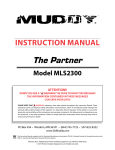
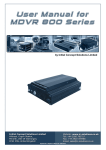
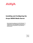
1
Watching The World PH PATROL User Guide User Manual for PHMDVR - X1 Version: 2.5 User Manual For PHMDVR – X1 Premier Hazard Ltd Bessingby Industrial Estate Bridlington YO16 4SJ UK TEL: +44(0)1262 670161. FAX: +44(0)1262 605666 THE INFORMATION IN THIS MANUAL WAS CURRENT WHEN PUBLISHED. THE MANUFACTURER RESERVES THE RIGHT TO REVISE AND IMPROVE ITS PRODUCTS. ALL SPECIFICATIONS ARE THEREFORE SUBJECT TO CHANGE WITHOUT ANY NOTICE. © Copyright by Premier Hazard Ltd All rights reserved.2012 2 / 58 User Manual for PHMDVR - X1 Version: 2.5 Table of contents 1 PRODUCT CHARACTERISTICS AND OVERVIEW .................................................................................................... 5 1.1 Product Overview ............................................................................................................................................ 5 2 HARDWARE OVERVIEW ............................................................................................................................................... 6 2.1 Front View ....................................................................................................................................................... 6 2.2 Back View ....................................................................................................................................................... 7 3 HANDHELD IR REMOTE CONTROL ............................................................................................................................ 8 3.1 HANDHELD IR CONTROL KEY FUNCTIONS: .............................................................................................. 10 4 MENU TREE..................................................................................................................................................................... 12 4.1 Menu tree structure ....................................................................................................................................... 12 5 SYSTEM STARTUP .......................................................................................................................................................13 5.1 System login for setup ................................................................................................................................... 14 6 SEARCH MENU ............................................................................................................................................................... 15 6.1 6.2 6.3 Search Option: All files .................................................................................................................................. 15 Video Playback on PHMDVR-X1 .................................................................................................................... 18 Search Option: Event Files ............................................................................................................................ 19 7 SETUP MENU .................................................................................................................................................................. 21 7.1 7.2 System Settings ............................................................................................................................................ 21 7.1.1 Date/Time ..............................................................................................................................2 2 7.1.2 General ..................................................................................................................................26 7.1.3 Register Info...........................................................................................................................28 7.1.4 Format ...................................................................................................................................29 7.1.5 Upgrade .................................................................................................................................30 7.1.6 User Security ..........................................................................................................................33 7.1.7 Config .....................................................................................................................................34 7.1.8 User Log .................................................................................................................................36 Record Settings ............................................................................................................................................. 37 7.2.1 Options ..................................................................................................................................37 © Copyright by Premier Hazard Ltd All rights reserved. 2012 3 / 58 User Manual for PHMDVR - X1 7.3 Version: 2.5 7.2.1 OSD Overlay ...........................................................................................................................40 7.2.2 Channel Setting......................................................................................................................42 7.2.3 Record Setting........................................................................................................................43 7.2.4 Schedule.................................................................................................................................45 Event Settings ............................................................................................................................................... 47 7.3.1 Sensor ....................................................................................................................................47 7.3.2 Speed .....................................................................................................................................48 7.3.3 Acceleration ...........................................................................................................................50 7.3.4 Temperature ..........................................................................................................................51 7.3.5 Camera...................................................................................................................................52 7.3.6 Voltage ...................................................................................................................................53 8 INFORMATION ............................................................................................................................................................... 54 8.1 System .......................................................................................................................................................... 54 8.2 History ........................................................................................................................................................... 55 9 ACRONYMS AND ABBREVIATIONS .......................................................................................................................... 57 10 TROUBLESHOOT GUIDE ............................................................................................................................................. 58 © Copyright by Premier Hazard Ltd All rights reserved. 2012 4 / 58 User Manual for PHMDVR - X1 Version: 2.5 1 PRODUCT CHARACTERISTICS AND OVERVIEW 1.1 PRODUCT OVERVIEW The PHMDVR-X1 is a cost-effective and functional Mobile Digital Video Recorder specially designed for vehicle surveillance, featuring a high-speed processor and embedded operating system. The advanced H.264 video compression and decompression makes the PHMDVR-X1 a very powerful solution for mobile video recording. VIDEO AND AUDIO PHMDVR-X1 FEATURES AND CAPABILITIES • 4 channels for video input (HD1 at 12fps or CIF at 25fps), continuous or priority video recording and live view display. • • Semi-transparent GUI setup enables live display and setup to work synchronously. Proprietary Special file system, NVRFSTM, improves the security level of data, provides selfrecovery function, self-check, self-backup for certain critical data and avoids data fragmentation that affects system efficiency. • • • • • • • • H.264 video compression (uses 50% less storage space than MPEG4) 4 channels for digitally recorded audio, synchronized audio matched to 4 video channels User friendly criteria to playback the events associated video only. Automatic timer to resume the live display if the unit is idle for user defined timings. User-selectable settings for quality and enable/disable audio recording for each video channel. 12V power supply for multiple devices such as cameras, sensors, relays and any other accessories. Selectable frame rate with event-triggered burst recording speeds up to 30FPS/camera. Multiple alarm inputs with selectable pre-alarm and post-alarm record timings. PLAYBACK CAPABILITIES Handheld Infra-Red controller with OSD for quick access to playback recorded video and settings menu. PC-Based Client software for live viewing, Video playback, and playback event associated video, and data downloading function. © Copyright by Premier Hazard Ltd All rights reserved. 2012 5 / 58 User Manual for PHMDVR - X1 Version: 2.5 2 HARDWARE OVERVIEW 2.1 FRONT VIEW A – Video Out – Video output for displaying unit OSD. RCA/Phono connector. B – IR – IR Sensor for the remote control. C – Unit Lock – The unit must be locked before turning the unit on. The unit will not turn on if the lock position is on open. D – DEBUG, MCU – For internal use only. E – Various LED’s. HDD – Status of Hard Drive’s presence. ALM – Status of an alarm condition. ERR – The unit has encountered an Error. PWR – The unit has power. REC – The Unit is recording. VLOSS – There is a video channel that has lost its video signal. E – USB – USB port for extraction video files and for firmware upgrades. © Copyright by Premier Hazard Ltd All rights reserved. 2012 6 / 58 User Manual for PHMDVR - X1 Version: 2.5 2.2 BACK VIEW A – DC8-32V – 6-pin Power input connector. B, C, D, E – AV IN1~4 - Video and Audio inputs. The four pins are for Video, Audio, 12V and Ground. F – I/O – Alarm I/O connector. G – Audio Out – Audio output. H – Video Out – Analog video output. © Copyright by Premier Hazard Ltd All rights reserved. 2012 7 / 58 User Manual for PHMDVR - X1 3 HANDHELD IR REMOTE CONTROL Version: 2.5 A B C D E F G H I J K L M N © Copyright by Premier Hazard Ltd All rights reserved. 2012 8 / 58 User Manual for PHMDVR - X1 Version: 2.5 A POWER - PHMDVR-X1 power ON/OFF Button. (Can also be used to put unit into sleep mode. Unit will stop Recording while in sleep mode.) B LOGIN/LOCK – Menu Entry Button. (May need login password if security has been enabled.) C NUMBER KEYPAD – 1~9, During setup, number keys are used to input values. Number keys are also used to select video channels. [+][-] keys are used to select next or previous values. key is used to swap between quad view and single channel view. D ZOOM [+][-] Used to Zoom IN\OUT a PTZ camera. E IRIS [+][-] PTZ Iris Control. F FOCUS [+][-] PTZ Focus Control. G NAVAGATION ARROWS - Use the ARROW keys to move between selections, input fields and icons. Select ENTER to select and EXIT to return. Next and previous is also used to increase or decrease volume when at live or search screens. H VGA – Switch the Output Mode to VGA. I VIDEO – Switch back from VGA mode to composite output. J INFO – Not used, - Brightness, Contrast and Colour Settings button – User can use [+][-] button to change setting per channel, SETUP – to get into SETUP page (may require password) and EXIT – Returns to a previous menu until the live monitor is displayed. K PAUSE/STEP - Freezes playback to a single frame and can advance one frame at a time. To advance the frame press Pause / Step to move frame by frame. Press EXIT to return to normal playback speed, PLAY – starts/resumes playback, SLOW - Reduces playback speed to 1/2, 1/4, 1/8 modes. Press PLAY to return to normal playback speed, GOTO - Quick search mode within the file playing back. Select the desired file and start to play. Press GOTO button and input the desired time. Select START to jump to the specific time, STOP - Used to stop the recording manually, RECORD - Used to start the recording manually. L PTZ - Start to active the PTZ function, CF – Not used, AUTO – Auto run the PTZ function, PRESET – Preset default position, RECALL – Recall the set program, BRUSH – Wipe the PTZ glass. M N F2, F3, F4 are Reserved for future use. F1 Button: Used for Auto-Exporting of Event Recorded files onto a USB stick (only for PHMDVR-X1 series) © Copyright by Premier Hazard Ltd .All rights reserved.2012 9 / 58 User Manual for PHMDVR - X1 Version: 2.5 Each PHMDVR-X1 includes a handheld Infra-Red (IR) controller that allows the user to control the recording module and display on-screen control menu. 3.1 HANDHELD IR CONTROL KEY FUNCTIONS: 1. NUMERIC KEYPAD: [0-9] keys: During setup, number keys are used to input values. For viewing channels 1, 2, 3 and 4 use buttons 1, 2, 3 and 4 on numeric keypad respectively. [+], [-] keys: During setup, plus and minus are used to select next or previous values. 2. SETUP MENU NAVIGATION: ▲, ▼: Up, down directional keys: Moves selection up and down in setup menu. ►, ◄: Left, Right directional keys: Moves cursor left or right in setup menu. [ENTER] key: During setup, select and save entry During Playback, displays all the information that setup in the OSD overlay menu. 3. OTHER KEY FUNCTIONS: VGA If the security is enabled in the setup, use LOGIN / LOCK or SETUP key to enter the user setup. It is important to remember the password as there is no function to restore the password. The Power button can reset the PHMDVR-X1 into sleep mode (unit will stop recording while in the sleep mode) Switch the output mode to VGA (Include: VGA1, VGA2, VGA3) VIDEO Switch back from VGA to composite output (V1) LOGIN/ LOCK POWER Swapping between multi-channel and single channel monitor While in surveillance screen only. Press this button to change the number of display channels. By pressing the key, the display channel changes in the sequence of four→ one→ two→ three→ four→ one SETUP EXIT Stop Record © Copyright by Premier Hazard Ltd . All rights reserved.2012 Brightness, Contrast, color adjustment per channel. Use [+] [-] button to change the values. User can adjust the values for each channel individually. System setting screen (may require login) Returns to the previous menu. Pressing exit key takes one step back until the live screen is displayed Used to stop the recording manually. Used to start the recording manually. 10 / 58 User Manual for PHMDVR - X1 Version 2.50 REW Freezes playback to a single frame and can advance one frame at a time. To advance the frame press Pause/Step to move frame by frame. Press EXIT to return to normal playback speed Starts/Resumes playback from any other mode (FF, RR, Frame by Frame etc) Reduces playback speed to 1/2, 1/4, 1/8 modes. Press PLAY to return to normal playback speed Quick search mode within the file playing back. Select the desired file and start to play. Press GOTO button and input the desired time. Select START to jump to the specific time Increase volume while playback (if audio is recorded) or multimedia playback Decrease volume while playback (if audio is recorded) or multimedia playback Rewinds the video while playback. X2 and X4 modes available FWD Fast forward the video while playback. X2 and X4 modes available CF No use at present PAUSE/STEP ▐► PLAY ► SLOW � GOTO Î NEXT • PREV .., [F2],[F3],[F4] Reserved for future use Be sure to check if the IR Remote has a set of AAA batteries. 4. PAN/TILT/ZOOM FUNCTIONS While connect with PTZ camera and using the RS232 in DB25, following commands can control the PTZ camera with following functions: [ZOOM IN +], [ZOOM OUT -] ZOOM IN/OUT [IRIS +], [IRIS-] IRIS control (focus function) [FOCUS +], [FOCUS -] FOCUS IN/OUT PTZ Start to active the PTZ function AUTO Auto run with the PTZ pattern PRESET Preset default position RECALL Recall the set program BRUSH Brush the glass screen © Copyright by Premier Hazard Ltd All rights reserved.2012 11 / 58 User Manual for PHMDVR - X1 Version 2.50 4 MENU TREE 4.1 MENU TREE STRUCTURE ICON MENU SUBMENU All Files SEARCH Event Files Date/Time General Register Info System Format Upgrade User Security Config Options OSD Overlay SETTINGS Record Channel Settings Record Settings Sub-Stream Schedule Sensor Speed Event Acceleration Temperature Camera System INFORMATION History © Copyright by Premier Hazard Ltd All rights reserved.2012 12 / 58 User Manual for PHMDVR - X1 Version 2.50 5 SYSTEM STARTUP After connecting the PHMDVR-X1 to a vehicle power supply, turn on the vehicle ignition and the unit will automatically start recording. Power is normally supplied to the PHMDVR-X1 as long as the vehicle ignition is ON. “Display only view” of the cameras will immediately be available to be viewed in quad view. Note: The system will ONLY automatically start recording if ‘GENERAL’ record mode is selected and the HDD\SD is formatted using the ‘Format’ option in the MDVR-1. The PHMDVR-X1 will not accept Microsoft Windows formatted card/drives (FAT, FAT32, NTFS) © Copyright by Premier Hazard Ltd All rights reserved.2012 13 / 58 User Manual for PHMDVR - X1 Version 2.50 5.1 SYSTEM LOGIN FOR SETUP MDVR-1-1 menu is semi-transparent; you can see the live view when you make GUI configurations • When the Password is set ‘enable’, press LOGIN/LOCK OR ENTER key on the handheld controller. DEVICE NO: The unit ID of MDVR-1. In the figure above this number is ‘0’. This value is configurable in the Settings->System->Register Info->Device ID option. PASSWORD: Enter the admin password or user password. Keyboard: Press 【Enter】 to use virtual keyboard to type device ID and password. 1. 0~9, number key, press 【Enter】 to select the number. 2. 123: Input type shift key. (Number, capital, small letter) 3. 【←】delete, 【 】Exit. User default User password is 22222222, and Admin password is 88888888. • When the Password is set to ‘disable’ mode, press the SETUP key on the handheld controller to directly get into the setup menu; © Copyright by Premier Hazard Ltd All rights reserved.2012 14 / 58 User Manual for PHMDVR - X1 Version 2.50 6 SEARCH MENU The first option in the Tree Menu Structure is the Search Option that allows you to browse and search the HD for recorded footage. 6.1 SEARCH OPTION: ALL FILES You can search all the video files including Normal recording files, Event files by Record time and File Type. Highlight the option ALL FILES and you go in the FILE SEARCH Mode. © Copyright by Premier Hazard Ltd All rights reserved.2012 15 / 58 User Manual for PHMDVR - X1 Version 2.50 FILE TYPE: ALL: Search for all file types including Event files and Normal Recording files. EVENT: Search only Event file types. CHANNEL: ALL: Search files from all camera channels: 1~4 DATE: PHMDVR-X1 system will display the current day automatically. The calendar displays the days in a particular month when the PHMDVR-X1 has recorded footage. . Days marked green indicate normal recording days. Days marked red indicate Event recording days as shown below: TIME: The default setting is 00:00:00; this time is for the start time for recording. For example: If the date is 2009_04_14 and the time is 00:00:00, it indicates that you want to search the entire video files from th 00:00:00 to 23:59 on 14 April 2009. © Copyright by Premier Hazard Ltd All rights reserved.2012 16 / 58 User Manual for PHMDVR - X1 Version 2.50 Press【SEARCH】to enter into the next menu for listing out all the video files that shows the details of the file type, date, time and its size. SEL: For selecting the files for backup. Press ← arrow key on remote control to select the file that needs to be backed up onto a Thumb drive. REV.: Reverse Selection: Used to inverse your existing selected files. Lock: L means this file is locked. U Means this file is unlock. EXPORT: Exports the selected files to a USB thumb drive using the USB port on the front panel of PHMDVR-X1. Only EVENT files can be locked since event files are very important. If the video file is locked, then the file cannot be deleted by HDD overwrite function. Only when you unlock the files, then HDD overwrite function will delete the files. Other option to delete the Locked files is by formatting the HD. © Copyright by Premier Hazard Ltd All rights reserved.2012 17 / 58 User Manual for PHMDVR - X1 Version 2.50 Connect the external storage device with PHMDVR-X1 by USB port and select【EXPORT】for backup. You will see the screen as shown below. If you do not connect external storage device or if the storage device is defective, then the system will display NO THUMB DRIVE. 6.2 VIDEO PLAYBACK ON PHMDVR-X1 For playing the recorded files, Select the files using the ENTER key on the remote. . If the current current Settings Settings in in MDVR-1 PHMDVR-X1 for Video for Video Type (Options: Settings->Record->OptionsType >Video Type) is PAL and the files in HD are recorded with NTSC Video Type, the MDVR-1 will not be able to Playback the files. (Options: Settings->Record->Options->Video Type) is PAL and the files in HD are You will have to change Video to NTSCwill in not (Settings->Record->Options->Video recorded with NTSC Videothe Type, the Type PHMDVR-X1 be able to Playback the files. Type = NTSC), save the option and Reboot the MDVR-1 to enable the playback of files You will have to change the Video Type to NTSC in (Settings->Record->Options->Video recorded in NTSC format. Type = NTSC), save the option and Reboot the PHMDVR-X1 to enable the playback of files recorded in NTSC format. The same applies vice versa for files recorded in PAL format. The same applies vice versa for files recorded in PAL format. © Copyright by Premier Hazard Ltd All rights reserved.2012 18 / 58 User Manual for PHMDVR - X1 Version 2.50 You will see the error as shown below if there is a Video Type mismatch with the current settings in the Record Options: 6.3 SEARCH OPTION: EVENT FILES This menu is used to search for all the event files on the HD. © Copyright by Premier Hazard Ltd All rights reserved.2012 19 / 58 User Manual for PHMDVR - X1 FILE TYPE: All – you can choose from the all or from the following options: I&O ALARM/ACCELERATION/SPEED/TEMP ALARM/VL ALARM as shown below: Other options in Event Search are similar to the ones given in Section 6.1 © Copyright by Premier Hazard Ltd All rights reserved.2012 20 / 58 Version 2.50 User Manual for PHMDVR - X1 Version 2.50 7 SETUP MENU The Setup Menu consists of various configurations for System (that is MDVR-1), Recording settings, Sensors used for Events and External Peripheral Settings as shown below: 7.1 SYSTEM SETTINGS Here you can configure various system Parameters, control the On-Screen Display, format drive and do firmware upgrade. © Copyright by Premier Hazard Ltd All rights reserved.2012 21 / 58 User Manual for PHMDVR - X1 Version 2.50 7.1.1 Date/Time DATE FORMAT (US or International): Choose the required setting for the date format using ENTER key. TIME FORMAT: 12H or 24H. Press【ENTER】to select different format. TIME SYNC SOURCE: The system allows to have the time synchronizing by either “GPS” or “NTP”. © Copyright by Premier Hazard Ltd All rights reserved.2012 22 / 58 User Manual for PHMDVR - X1 Version 2.50 A: While selecting the “GPS”, the device must have GPS connection and GPS signal must have good reception signal. B: While selecting the “NTP” (Network Time Protocol), the device must have network access connection and should be assigned the NTP IP location; This process will run at 6:30am local time while the system have network connection. TIME ZONE: Please choose the correct time zone where the vehicle is located. NTP SERVER IP: Input the IP server does support NTP protocol, in order to allow the system can have time synchronization through the network. [Example: "192.43.244.18", "129.6.15.28", etc] © Copyright by Premier Hazard Ltd All rights reserved.2012 23 / 58 User Manual for PHMDVR - X1 Version 2.50 DST: Daylight Saving Time. Only when it set on, the following options will available. Auto Mode will select the Auto DST mode. While setting the DST, the former date must be smaller than the later date; if the two settings Dates are the same, the DST will be invalid. In Custom mode you can set your desired value for the Time and Date. © Copyright by Premier Hazard Ltd All rights reserved.2012 24 / 58 User Manual for PHMDVR - X1 Select【SAVE】to save your settings. © Copyright by Premier Hazard Ltd All rights reserved.2012 25 / 58 Version 2.50 User Manual for PHMDVR - X1 Version 2.50 7.1.2 General ON/OFF TYPE: The PHMDVR-X1 can start with the Vehicle Ignition or with preset Timer. © Copyright by Premier Hazard Ltd All rights reserved.2012 26 / 58 User Manual for PHMDVR - X1 Version 2.50 IGNITION: for shut down delay function. For example: If you set the shut down delay time as 5 min, then PHMDVR-X1 will shut down after 5 min after the ignition off. TIMER: It will start up automatically at the time your setup. If you select TIMER, then the following screen will pop up. Here you can choose your Boot-up and shutdown time. BUZZER SWITCH: ON/OFF – Enables an audible buzzer on event and startup. IDLE TIME: The time for the operation interface switching to the live view. If the user does not make some operation for some time via IR remote, the system will switch to the live view automatically. For TIMER type, if the setting for Boot Up time is 6:00:00 and Shut down time is 11:00:00, the device will boot up automatically at 6am and shutdown at 11am. After 11 am you need to use the IR remote to start the DVR and if the PHMDVR-X1 is idle, it will shut down in 5 minutes. EVENT FILES AUTO-EXPORT (USB): This feature allows you to automatically export ALL the Event files present on the HD onto a USB memory. For using this, insert an empty USB drive in the USB slot provided in front of the PHMDVR-X1 panel. Then Select the ‘F1’ option from your IR remote, you will see all the events files (if present on the HD) will be exported to the drive in a folder named ‘00000’. © Copyright by Premier Hazard Ltd All rights reserved.2012 27 / 58 User Manual for PHMDVR - X1 Version 2.50 7.1.3 Register Info UNIT S/N: This is a unique Serial Number of the PHMDVR-X1 that cannot be changed. UNIT ID: Device ID. Use the NUMERIC keypad to enter the system ID from 00000 to 99999. This ID is used when logging in to the unit. © Copyright by Premier Hazard Ltd. All rights reserved. 2012 28 / 58 User Manual for PHMDVR - X1 Version 2.50 COMPANY NAME: The name of a company. Use the ENTER key to get the options for inputting the name of the company. VEHICLE NO.: The number of the vehicle. DRIVER/ROUTE NAME: The driver’s name or the route name VEHICLE S/N FOR CMS: Mandatory This is very important Serial number and only recognized by the CMS software. Remark: While using the CMS to connect to a MDVR-1, make sure vehicle No. and vehicle S/N are not blank, else the device will not get listed in the Message Server used by CMS. Scroll to 【SAVE】 to make the setting valid 7.1.4 Format Select the device you want to format HDD, SD card or external USB storage device. © Copyright by Premier Hazard Ltd. All rights reserved. 2012 29 / 58 User Manual for PHMDVR - X1 Version 2.50 DEVICE: Please press 【ENTER】 to select the target device for format. There are 3 options: HDD, SD and USB. Then press 【FORMAT】 to format the storage device. After format success, it will restart automatically. It’s very important to format the drive or storage medium before using the PHMDVR-X1 on first use. 7.1.5 Upgrade © Copyright by Premier Hazard Ltd. All rights reserved. 2012 30 / 58 User Manual for PHMDVR - X1 Version 2.50 FIRMWARE: Upgrades the firmware. MCU: Upgrades the MCU. HOW TO UPGRADE THE FIRMWARE: - Create one folder named dvrupgrade on a thumb drive and then copy the firmware upgrade file into this folder. - Insert the thumb drive into the USB port on the front panel of MDVR-1. - Enter into the Firmware Upgrade option and Select UPGRADE】, PHMDVR-X1 will upgrade the firmware automatically. - During the firmware upgrade, then following screen will pop up. Note: DO NOT REMOVE THE USB DRIVE WHILE FIRMWARE UPGRADE. Doing so might make the PHMDVR-X1 unstable. © Copyright by Premier Hazard Ltd. All rights reserved. 2012 31 / 58 User Manual for PHMDVR - X1 - Version 2.50 After upgrade success, it will restart automatically, as follows: If the firmware of the PHMDVR-X1 is the latest, then you cannot upgrade the firmware again. And PHMDVR-X1 system will pop up one screen as following: MCU UPGRADE: For development ONLY. © Copyright by Premier Hazard Ltd. All rights reserved. 2012 32 / 58 User Manual for PHMDVR - X1 7.1.6 User Security Setup the password for user and admin. © Copyright by Premier Hazard Ltd. All rights reserved.2012 34 / 58 Version 2.50 User Manual for PHMDVR - X1 Version 2.50 PASSWORD ENABLE: By enabling this function you will require a password in order to access the setup menu. Selecting “OFF” will disable this function. USER PASSWORD: User rights where they can only search files but cannot modify any parameters. ADMIN PASSWORD: An Administrator password that provided full rights to the MDVR-1 Re-enter Password must be same input as first password, if there is a mismatch in the passwords, you will get an error. 7.1.7 Config © Copyright by Premier Hazard Ltd. All rights reserved.2012 35 / 58 User Manual for PHMDVR - X1 Version 2.50 RESTORE: Restores to default factory settings. EXPORT: Exports the MDVR-1’s current configuration to a USB thumb drive or an external HDD in a file named ‘MDVRCFG.cfg’. With this feature you can preset all required values for a PHMDVR-X1 and then import them on all other PHMDVR-X1 to have the same configuration. IMPORT: Imports a MDVR-1’s configuration file to the current device. Insert the external storage device to the USB port that contains the configuration file that is exported from another PHMDVR-X1 (‘MDVRCFG.cfg’) in the storage device and then Select【IMPORT】option. The configuration will be imported to the PHMDVR-X1 automatically. © Copyright by Premier Hazard Ltd. All rights reserved.2012 36 / 58 User Manual for PHMDVR - X1 Version 2.50 7.1.8 User Log You can export or delete the user log in this interface, as shown below: It informs you when the device was accessed using the IR remote. © Copyright by Premier Hazard Ltd. All rights reserved.2012 37 / 58 User Manual for PHMDVR - X1 Version 2.50 7.2 RECORD SETTINGS All the settings related with the Recording options and Camera Setup is accessible in this menu 7.2.1 Options This is the setup for the basic parameters of recording. © Copyright by Premier Hazard Ltd. All rights reserved.2012 38 / 58 User Manual for PHMDVR - X1 Version 2.50 VIDEO TYPE: Changing Video standards to PAL or NTSC. The default setting is NTSC RECORD MODE: Setting for the Record mode, Three modes are available as following: GENERAL: Normal recording at all times after power up. TIMER: PHMDVR-X1 will start to record at defined time setting in the TIMER RECORD menu based on the schedule based on the options set in SETTINGS->RECORD->SCHEDULE menu EVENT: When an Event is trigged, PHMDVR-X1 will make the Event Recording. The events are triggered by various I/O peripherals and Sensors connected to the MDVR-1. These are all configurable NORMAL REC RATE: Normal record rate, two option: NORMAL: PHMDVR-X1 will start to record according to the setup in RECORD->RECORD SETTING. 1 FRAME: PHMDVR-X1 will only record at one frame per second without Audio in order to take less space of hard drive. When an Event is triggered, PHMDVR-X1 will always record according to the values that are set in SETTINGS->RECORD->RECORD SETTINGS. So you always have good quality for Events. ALARM PRE-REC TIME (1-60) MIN: Pre-record time setting from 1 to 60 minutes. For example: If the setting for pre-record is 30min, when alarm is triggered at 10:30, then the record file will start from 10:00 to 10:30 and it will make this as alarm record. The PHMDVR-X1 can buffer upto 60 minutes of past video data. ALARM DURATION(3-30)SEC: The settings for consecutive and successive Alarms. Example: If we set the duration to be 5 sec, then multiple Alarm events triggered within 5secs will be treated as 1 Alarm event ALARM POST REC(30-1800)SEC: Alarm post recording time setting. The PHMDVR-X1 can record video data for 30min post an Alarm trigger event The total Alarm Footage duration will be = Alarm Pre-Rec. Time + Alarm Post-Rec. Time ALARM TIME in sec (for Buzzer): This is the Buzzer alarm duration time setup when an alarm is triggered. The PHMDVR-X1 has an internal buzzer. © Copyright by Premier Hazard Ltd. All rights reserved.2012 39 / 58 User Manual for PHMDVR - X1 Version 2.50 MEDADATA CAPTURE: Metadata information enabling in the Video file. RECORD FILE TIME(MIN): recording file packing size 15, 30, 45, 60 minutes optional HDD/SD OVERWRITE: To make the HDD overwrite when there is only 2GB space left in HDD. ON: When hard drive space remaining is less than 2G, then according to “First in first out” rule, system will start to delete the earliest record files till HDD space equal or over 10G (except the alarm file which in locked time). OFF: Device will stop recording when hard drive space is full (less than 500M). You must replace an HDD or delete recorded file s manually, and then it will start to record. LOCKED FILE RETENTION (DAY): Time to keep the Event files in a Locked condition so that it will not be overwritten when HD is full. Options are in days:: 7, 10, 15, 20, 30, 45 days, After the time for locking period has elapsed, you can unlock the files using the ‘UNLOCK’ option. © Copyright by Premier Hazard Ltd. All rights reserved.2012 40 / 58 User Manual for PHMDVR - X1 Version 2.50 7.2.1 OSD Overlay During Live view, the OSD Overlay option provides with various Status information instantly on the screen when you press 【Enter】 on remote control © Copyright by Premier Hazard Ltd. All rights reserved.2012 41 / 58 User Manual for PHMDVR - X1 Version 2.50 DATE/TIME: Display date and time on OSD. ALARM: Display Alarm information on OSD. ACCELERATION DATA: Display the information for inertial sensor. TEMPERATURE: Display the temperature on OSD FIRMWARE VERSION: Display the current firmware version GPS: Displays the status of GPS. If all the options are ON, Then the following screen will pop up after you press 【Enter】 during live view. © Copyright by Premier Hazard Ltd All rights reserved.2012 41 / 58 User Manual for PHMDVR - X1 Version 2.50 7.2.2 Channel Setting This option enables record function and live view for each channel. CH ID: The ID of a Video Channel. EN: Enable/Disable the record function for a particular channel. You will still be able to see the channel in live view but not in CMS. © Copyright by Premier Hazard Ltd All rights reserved.2012 42 / 58 User Manual for PHMDVR - X1 Version 2.50 NAME: The name of the channel. For example, if you setup the name of CH1 is ABC, and you can see ABC three letters display on the live view (for channel 1). The Name field can take 8 alpha numeric characters. AUDIO: Activates the audio record function for a particular channel. LIVE: Enables/disables the live view. This does not affect CMS and local recording in the HD. ROUND: Enables the channels looping function. In Live View this option displays each of the 4 channels in a full screen mode in a sequential order one at a time. 7.2.3 Record Setting Make the configuration setup for Resolution, Frame rate and, Image quality parameter for each channel. © Copyright by Premier Hazard Ltd All rights reserved.2012 43 / 58 User Manual for PHMDVR - X1 Version 2.50 RES: Resolution, D1, HD1, CIF. The following formats are currently supported: FOR PAL: 1) CIF (Common Intermediate Format): 352X288 2) QCIF (Quarter CIF):: 176X144 ; Available in Mode1 for SubStream Mode in CMS, used for low bandwidth links over 3G. 3) HD1 (Half D1): 704X288 4) D1 (Full Resolution for TV): 704X576 FOR NTSC: 1) CIF (Common Intermediate Format): 360X240 2) QCIF (Quarter CIF): 176X120 ; Available in Mode1 for SubStream Mode in CMS, used for low bandwidth links over 3G 3) HD1: (Half D1) 720X240 4) D1 (Full Resolution for TV): 720X480 FR: Frame rate, frames per second, 1~25 for PAL mode and 1~30 levels for NTSC mode for a particular resolution. QUALITY: Image quality, 8 levels available, Level 1 sets the PHMDVR-X1 to record at highest quality. Normal quality: Is the quality for normal record, and alarm quality is for alarm record. © Copyright by Premier Hazard Ltd All rights reserved.2012 44 / 58 User Manual for PHMDVR - X1 Version 2.50 7.2.4 Schedule Schedule allows you to configure TIMER-based recording for the PHMDVR-X1 as per the settings done in SETTINGS->SYSTEM->GENERAL->ON/OFF Type as TIMER. For details refer to Section 7.1.2. Date: Press ENTER to change the period of time to control the recording schedule © Copyright by Premier Hazard Ltd All rights reserved.2012 45 / 58 User Manual for PHMDVR - X1 Version 2.50 ‹ Single Day: Choose the name of a day to create a recording schedule ‹ Every Day: Choose “Every” to apply a schedule to every day of the week ‹ Weekday: Schedule will only apply Weekdays (weekday is from Monday to Friday) ‹ **********: Choosing the asterisks will disable the highlighted schedule Schedule 1 / 2: ‹ ‹ ‹ The 4 values in time AA:BB-CC:DD are the Start (AA:BB) and Stop (CC:DD) times. Press the RIGHT ARROW key to enter values using the NUMERIC keypad into any time field; Schedule 1 is the first of two possible ON/OFF cycles that apply to any day in the period chosen under Date. ‹ Schedule 2 is the second cycle for any day in the period. There is no need to overlap times of ‹ Schedule 1 and Schedule 2. Ending at 23:59 of one day and beginning with 00:00 of the next day will provide continuous recording without interruption (factory default setting) Type: Press ENTER to change the type of the recording mode: Con: Continuous recording ‹ ‹ Alarm: © Copyright by Premier Hazard Ltd All rights reserved.2012 Alarm recording 46 / 58 User Manual for PHMDVR - X1 Version 2.50 7.3 EVENT SETTINGS The Event Settings Menu is used for setting various options for External Sensor inputs for the MDVR-1. 7.3.1 Sensor © Copyright by Premier Hazard Ltd All rights reserved.2012 47 / 58 User Manual for PHMDVR - X1 Version 2.50 PHMDVR-X1 supports 6 sensors as Input. EN: Enables the Sensor inputs. NAME: Press ENTER from IR Remote at the Name field to display the keyboard. Enter text name to identify the source of each Sensor connected to the unit. OSD: Input the numbers and Characters, they will be embedded into the Alarm video files (Event Files) when alarms occur, and it will also displayed in live view. SET: LOW (normal close) means high to low trigger alarm and HIGH (normal open) means low to high trigger alarm. ALARM: Press ENTER to select between OFF or ON: ON means when sensor triggered, alarm LED will flash, until next login onto the system after which the flashing will stop. Also, if the security is set to OFF for Login to PHMDVR-X1 then by just pressing ENTER on Remote can reset the flashing. LOCK: To enable the event does not erase during the over-write process of hard disk; If switch/alarm/log/lock all set as ON, When sensor triggered, it will trigger alarm signal and event log, it will also trigger alarm recording and event recording, besides, the EVENT LOG can’t be deleted even HDD-formatted or overwrite. 7.3.2 Speed Setup the alarm for over-speeding and other parameters related with Speed of Vehicle. © Copyright by Premier Hazard Ltd All rights reserved.2012 48 / 58 User Manual for PHMDVR - X1 Version 2.50 Speed SOURCE: PHMDVR-X1 is capable of capturing vehicle speed via GPS antenna or Vehicle-- speedometer. Browse between the settings of GPS or speedometer from the list. Please note that the GPS antenna should be connected to PHMDVR-X1 to receive satellite signals for speed. For more information on capturing speed from speedometer please contact local distributor for more technical support; SPD CHECK: Speed check is used to calibrate the offset speed when connected to the speedometer. That’s to say, the check only available when speed source is vehicle. Input the first area with the vehicle speed, for example at 80 (in KM/H) Start the vehicle and the second area will show the data from speedometer (in HZ) When the vehicle reaches 80 KM/H (shown in vehicle meter or dash board), and keep this speed at 30 seconds, then press the “Check” to make the system calibrate the second area (HZ) set as first area data (80); OVER SPEED: If the vehicle exceeds the SPD, PHMDVR-X1 will trigger the alarm signal (when the following option ALARM set as YES) until the driver slows down the speed LOW SPEED: If the vehicle exceeds the high speed limit, PHMDVR-X1 will trigger the alarm signal (when the following option ALARM set as YES) until the Admin password is entered to acknowledge the alarm. © Copyright by Premier Hazard Ltd All rights reserved.2012 49 / 58 User Manual for PHMDVR - X1 Version 2.50 7.3.3 Acceleration There are 3 values for G force Inertial Sensor: X, Y, and Z. X indicate forward and backward. X, Y indicates left and right and Z indicated up and down. Threshold is the limitation for the value, if the value set is larger than the setting in the menu, then PHMDVR-X1 will generate an alarm. NOTE: This function only can be activated when the PHMDVR-X1 is connected with an inertial sensor © Copyright by Premier Hazard Ltd All rights reserved.2012 50 / 58 User Manual for PHMDVR - X1 Version 2.50 7.3.4 Temperature Settings for temperature checks: There are two kind temperature checks: If the working temperature of PHMDVR-X1 is higher than the setting for HIGH TEMP, PHMDVR-X1 will generate alarm. If the working temperature of PHMDVR-X1 is lower than the setting for LOW TEMP, PHMDVR-X1 will generate alarm. © Copyright by Premier Hazard Ltd All rights reserved.2012 51 / 58 User Manual for PHMDVR - X1 Version 2.50 7.3.5 Camera CH ID: Channel number VIDEO LOSS: Alarm for video loss if no camera is connected. Only creates a log for alarm and no video file is saved. © Copyright by Premier Hazard Ltd All rights reserved.2012 52 / 58 User Manual for PHMDVR - X1 Version 2.50 7.3.6 Voltage This function is used for Vehicle Battery Protection. If the PHMDVR-X1 is not connected to the Ignition but connected to the Vehicle Battery and if the Voltage falls below the set threshold in this menu then an Alarm will be generated. Subsequently, the CMS will receive a message that that device will shutdown in 5 min as per the settings shown above. © Copyright by Premier Hazard Ltd All rights reserved.2012 53 / 58 User Manual for PHMDVR - X1 Version 2.50 8 INFORMATION The information menu is used for getting Status information for the PHMDVR-X1 with respect to Hard Drive Space, the module connected and the Firmware versions used in the system. 8.1 SYSTEM This menu displays the MCU version, firmware version, HDD status and SD card information. © Copyright by Premier Hazard Ltd. All rights reserved.2012 54 / 58 User Manual for PHMDVR - X1 1, NO HDD means No HDD installed or the HDD is defective and cannot work. © Copyright by Premier Hazard Ltd. All rights reserved.2012 55 / 58 Version 2.50 User Manual for PHMDVR - X1 Version 2.50 2, NO FORMAT means HDD installed but not formatted. 3, showing the detailed information for HDD means HDD works fine. 8.2 HISTORY Provides with historical data for the system with respect to the sensors connected to the MDVR-1. All images shown below show the different values for Sensors like Speed, Inertia Sensor, etc. © Copyright by Premier Hazard Ltd. All rights reserved.2012 56 / 58 User Manual for PHMDVR - X1 Select CLEAR to erase history logs. © Copyright by Premier Hazard Ltd. All rights reserved.2012 56 / 58 Version 2.50 User Manual for PHMDVR - X1 9 ACRONYMS AND ABBREVIATIONS HD OSD H.264 MPEG4 CIF HD1 D1 FPS IR USB CMS © Copyright by Premier Hazard Ltd. All rights reserved.2012 Hard Disk On Screen Display Video encoding format made by the MPEG group Video encoding format made by the MPEG group Common Intermediate Format Half D1 Resolution TV Resolution Frames per Second Infra Red Universal Serial Bus Central Management System 57 / 58 Version 2.50 User Manual for PHMDVR - X1 Version 2.50 10 TROUBLESHOOT GUIDE ¾ Problem: PHMDVR-X1 not starting up. Cannot use the remote control to start the MDVR-1 Step 1: Check if the Hard drive is present inside the casing. This is notified by the HDD (Hard Disc Drive) LED which goes green if HD is present. Step 2: Check if the Hard drive is formatted properly using the PHMDVR-X1 Setup menu. If not then reformat the drive. Note: windows formatted discs will not work! Step 3: Check if the Hard drive LOCK is in Lock position Step 4: Check if the proper DC supply of Hard drive LOCK is in Lock position Step 5: Check that the DC power supply is within 8V-32V range Step 6: Finally check if the batteries are in the remote and in working condition. ¾ Problem: PHMDVR-X1 shows the VL (Video Loss) LED blinking If a camera is not connected to the device (from required 4 cameras), then this LED will blink indicating a loss of video. There is no fault in device ¾ Problem: PHMDVR-X1 shows the ERR LED blinking If there is no Hard Drive detected or if the Hard Disk Caddy is not connected properly then you shall see the ERR LED blinking. So do check that the HDD caddy is connected and that the Hard Disk is formatted as explained in Section 7.1.4 © Copyright by Premier Hazard Ltd. All rights reserved.2012 58 / 58 A PSE Group Company Bessingby Industrial Estate Bridlington YO16 4SJ t. +44 (0)113 2391111 t. +44 (0)1262 670161 f. +44 (0)113 2391131 w. www.premierhazard.co.uk e. [email protected]