1
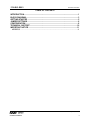
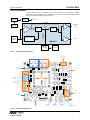
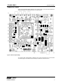
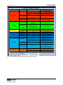
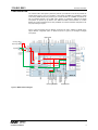
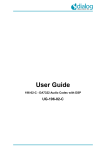
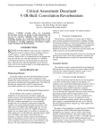
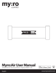
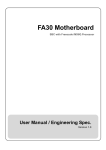
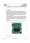
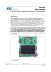
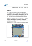
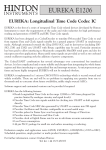
w 1700-EV1-REV1 Customer User Manual DOC TYPE: Customer User Manual BOARD REFERENCE: 1700-EV1-REV1 BOARD TYPE: Customer Main Board WOLFSON DEVICE(S): WM1811A DATE: July 2014 DOC REVISION: Rev 1.2 INTRODUCTION The 1700-EV1-REV1 customer evaluation board provides a complete hardware platform for the evaluation of all the WM7xxx microphone mini boards (coupons). The 1700-EV1-REV1 main board requires a 6220 compatible CODEC mini board e.g. WM1811A-6220-CS80-M-REVx board. The device kit includes a WISCE panel and configurations files which are written for WM1811A. WM1811, WM8994 and WM8958 can also be used with the 1700-EV1-REV1 board with their WISCE configuration files. Configurations covered are listed below: Digital or Analogue microphone loopback via ADC and DAC with headphone output Digital or Analogue microphone loopback via ADC and DAC with Line Out output Digital or Analogue microphone recording via S/PDIFF out Analogue microphone bypass to headphone output or Line Out output (full analogue path) Supports mono or stereo microphones (digital or analogue but not together) Supports Differential and single ended PGA circuit configuration, volume, mute controls. This document should be used as a starting point for evaluation of 1700-EV1-REV1 but it will not cover every possible configuration. Note: For the 6220 compatible CODEC mini board e.g. WM1811A-6220-CS80-M-REVx. The ‘x’ represents any revision preferably the latest revision. Assumptions: 1. The user is familiar with the WM7xxx boards (see relevant documents below) 2. The user has installed the device kit for 1700-EV1-REV1 and has set up WISCE as per instructions and is controlling the WM1811A. Note: The device kit requires WISCE pre-installed in your PC. You can download the latest version of WISCE from the following link: www.wolfsonmicro.com/wisce/WISCESetup.zip Related documents: 1. WM1811A datasheet 2. WISCE Quick Start Guide.pdf 3. WM7xxx example configurations and schematic. 4. 1700-EV1-REV1 schematic and layout pdf documents 5. WM1811A-6220-CS80-M-REVx schematic and layout pdf documents WOLFSON MICROELECTRONICS plc July 2014, Rev 1.2 Copyright 2014 Wolfson Microelectronics plc 1700-EV1-REV1 Customer Information TABLE OF CONTENTS INTRODUCTION ............................................................................................................. 1 BLOCK DIAGRAM ......................................................................................................... 3 GETTING STARTED ...................................................................................................... 5 JUMPER SETTINGS ...................................................................................................... 6 CONFIGURATION .......................................................................................................... 8 TECHNICAL SUPPORT ............................................................................................... 10 IMPORTANT NOTICE .................................................................................................. 11 ADDRESS: ............................................................................................................................11 w Customer Information July 2014, Rev 1.2 2 1700-EV1-REV1 Customer Information BLOCK DIAGRAM This test system focuses on evaluation of the 1700-EV1-REV1 with the WOLFSON CODEC WM1811A. The block diagram of the 1700-EV1-REV1 main board with WM1811A-6220-CS80-MREVx as complete test system is shown in Figure 1. USB Input Regulators 3.3V/1.8V Bypass Path USB Controller PGA (IN1L/R) Digital MIC Interfaces Headphone Out HPOUT DAC Recording to S/PDIFF Out MIC Inputs (Digital/ Analogue) ADC Loop back path Line Out Line Out WM1811A WM8804 Transceiver SPDIF OUT Figure 1 1700-EV1-REV1 Block Diagram Line In External Supply for Board and Micbias Line Out Left Mic Connector 9V Battery 6220 Mini Board Connectors Analogue Mic SMBs Digital Mic SMBs PCM Out Right Mic Connector USB External Clock S/PDIFF Out Optical S/PDIFF In Optical S/PDIFF Out Electrical Figure 2 1700-EV1-REV1 Main Board w Customer Information July 2014, Rev 1.2 3 1700-EV1-REV1 Customer Information Orientation Marker Headphone Out Figure 3 6220 Mini Board with WM1811A CODEC (WM1811A-6220-CS80-M-REVx) w Customer Information July 2014, Rev 1.2 4 1700-EV1-REV1 Customer Information GETTING STARTED To get started, the following steps need to be followed: a) Follow the mini board orientation marker, insert the CODEC mini board (WM1811A-6220-CS80M-REVx) onto the Main board (1700-EV1-REV1). b) Configure Jumpers (See Jumper Settings section). c) Insert/connect the analogue or digital microphones to the main board. These microphones could be Wolfson’s mini microphone boards/coupons which could be inserted into the on-board microphone sockets. The analogue microphones can also be connected via Line In phono sockets. If mini microphone boards/coupons are used then the acoustic port hole of the microphone coupon should face the arrow marked on the main board. d) Connect the main board to the PC/Laptop using a USB cable. The 1700-EV1-REV1 board is controlled via USB with Wolfson’s in house software WISCE. By default the board is powered by USB as well. Check on the control bar to make sure USB control is connected to the board. e) Open WISCE and load corresponding device (if you have installed the device kit for the 1700EV1-REV1 then you don’t have to load the device, just open WISCE and the device will be preloaded). f) Load device register settings by loading appropriate txt file. If you have installed the device kit then you can just use the WISCE panel which has been created for WM1811A with various use cases for both analogue and digital microphones. Just click on the required microphone use case and it will automatically load the appropriate register settings. In order to access this panel go to WISCE -> Scenarios -> MEMS and select ‘Mics Use Cases’ page. The following sections of this document will explain into details about the board and how to set it up to fulfil your evaluation. w Customer Information July 2014, Rev 1.2 5 1700-EV1-REV1 Customer Information JUMPER SETTINGS Figure 4 shows the default jumper settings for the 1700-EV1-REV1 main board with the WM1811A6220-CS80-M-REVx mini board attached to it as complete system. Figure 4 Default Jumper Settings The 1700-EV1-REV1 offers flexibility for different types of inputs and outputs to be connected/used. The following figure shows different jumper settings for possible I/O board connections. w Customer Information July 2014, Rev 1.2 6 1700-EV1-REV1 Customer Information 1700-EV1 Jumper Settings Connection Connector Type Location Left Mic Socket (J11) Mic Socket (De fa ul t) Right Mic Socket (J55) Analogue Mic SMBs (Onl y Ri ght Mi c Pos s i bl e ) Line In via Phono Connectors (Onl y Le ft Digital Mic S/PDIFF Out Supply Voltage MICBIAS Master Clock Jumper Settings Set J13 to position 1-2 Set J15 to position 1-2 Set J27 to position 1-2 Set J30 to position 1-2 AMIC_P (J28) Set J27 to position 2-3 AMIC_N (J33) Set J30 to position 2-3 IN1LP (J5) Set J13 to position 2-3 Mi c Pos s i bl e ) IN1LN (J6) Set J15 to position 2-3 Mic Socket (De fa ul t) Left Mic Socket (J11) Or Right Mic (J55) Set J20 to position 1-2 Set J57 to position 1-2 LRSEL_SMB (J37) DMICDAT_SMB (J21) Set J20 to position 2-3 Mi c Pos s i bl e de pe ndi ng on the DMICCLK_OUT (J47) Set J57 to position 2-3 LRSEL) MICBIAS_SMB (J41) * For LRSEL_SMB (J37) set J38 to position 1-2 for LR High and position 2-3 for LR Low Optical U16 Set J50 to position 2-3 Electrical (De fa ul t) J60 Set J50 to position 1-2 USB J58 Set J35 to position 2-3 Set J35 to position 1-2 External +5V J1 Set J4 to position 1-2 Set J35 to position 1-2 9V Battery BAT1 Set J4 to position 2-3 Set J18 to position 2-3 MICBIAS1 Set J19 to position 1-2 From CODEC (De fa ul t) Set J18 to position 2-3 MICBIAS2 Set J19 to position 2-3 External MICBIAS Set J18 to position 1-2 J1 Supply Set J17 to position 2-3 Set J18 to position 1-2 MICBIAS From Set J17 to position 1-2 1.8V or 3.3V Onbaord Regulators For 1.8V Set J16 to position 1-2 For 3.3V Set J16 to position 2-3 External MCLK via External MCLK via J61 Set J54 to position 2-3 SMB or On Board oscillator On Board Oscillator Y2 Set J54 to position 1-2 SMBs (Le ft Or Ri ght Figure 5 1700-EV1-REV1 Jumper Settings for Different Inputs and Outputs w Customer Information July 2014, Rev 1.2 7 1700-EV1-REV1 CONFIGURATION Customer Information The 1700-EV1-REV1 test system by default is powered up via USB but it can also be powered via external power supply of +5V or by 9V battery. In this system, the WM1811A is operating in master mode and by default the MCLK is provided by an on-board oscillator of 12.288MHz. This MCLK can also be provided externally via an SMB cable. Similarly, by default the analogue and digital microphones are powered up by Micbias1 from WM811A CODEC. External Micbias or on-board Micbias via on-board regulators are the other possibilities. For all these hardware configurations, see the jumper settings in Figure 5. Figure 7 shows the WISCE panel for different microphone use cases, available on ‘MEMS’ tab to support different configuration paths on WM1811A (shown in figure 6) for analogue and digital microphones. Bypass Paths Left Analogue MIC Right Analogue MIC Digital MICs WM1811A Recording to S/PDIFF Loopback Paths Figure 6 WM1811A Block Diagram w Customer Information July 2014, Rev 1.2 8 1700-EV1-REV1 Customer Information Figure 7 Microphone Use Cases Page in the MEMS WISCE Panel It should be noted that on the panel, the ‘Analogue Input Volume’ for the analogue microphones refer to the input PGA volume IN1L and IN1R of the WM1811A CODEC. The ‘Digital Input (AIF1_ADC) Volume’ refers to the audio interface volume and it is only applicable for the ‘Recording to S/PDIFF’ path (See Figure 6). It should also be noted that if you are powering up the microphones via external Micbias then ‘MICBIAS’ value should be adjusted accordingly on panel. It should also be noted that there is only one Line Out on the main board, therefore; only one channel of the CODEC can has its output via Lineout. For the Lineout, the register settings on the microphone use case WISCE panel are configured to output only the Right Channel of the CODEC. So, regardless of digital or analogue microphone, if line out is required, then attach the microphone to the right channel. For optimum performance the analogue microphones are configured in the pseudo-differential mode. The analogue microphones can also be configured in the single-ended mode but for simplicity the default jumper settings and WISCE panel caters only pseudo-differential mode. For differential and single ended mode please see the schematic diagram of 1700-EV1-REV1 and the datasheet of WM1811A. On the 1700-EV1-REV1 board, the LRSEL on the left microphone socket is tied to Micbias (logic high) while for the right microphone socket it is tied to GND (logic low). For the digital microphone SMBs connection, the LRSEL can be tied high or low by adjusting the jumper settings on J38 (see Figure 5). The 1700-EV1-REV1 along with WM1811A system is configured to provide the DMICCLK frequency of 3.072MHz. In all the use cases of digital microphones on the WISCE panel, the DMICCLK frequency of 3.072 has been used. For further details of other possible DMICCLK frequencies please see the WM1811A datasheet. w Customer Information July 2014, Rev 1.2 9 1700-EV1-REV1 Customer Information TECHNICAL SUPPORT If you require more information or require technical support, please contact the nearest Wolfson Microelectronics regional office: http://www.wolfsonmicro.com/contact or one of our global distributors: http://www.wolfsonmicro.com/distribution w Customer Information July 2014, Rev 1.2 10 Customer Information 1700-EV1-REV1 IMPORTANT NOTICE Wolfson Microelectronics plc (“Wolfson”) products and services are sold subject to Wolfson’s terms and conditions of sale, delivery and payment supplied at the time of order acknowledgement. Wolfson warrants performance of its products to the specifications in effect at the date of shipment. Wolfson reserves the right to make changes to its products and specifications or to discontinue any product or service without notice. Customers should therefore obtain the latest version of relevant information from Wolfson to verify that the information is current. Testing and other quality control techniques are utilised to the extent Wolfson deems necessary to support its warranty. Specific testing of all parameters of each device is not necessarily performed unless required by law or regulation. In order to minimise risks associated with customer applications, the customer must use adequate design and operating safeguards to minimise inherent or procedural hazards. Wolfson is not liable for applications assistance or customer product design. The customer is solely responsible for its selection and use of Wolfson products. Wolfson is not liable for such selection or use nor for use of any circuitry other than circuitry entirely embodied in a Wolfson product. Wolfson’s products are not intended for use in life support systems, appliances, nuclear systems or systems where malfunction can reasonably be expected to result in personal injury, death or severe property or environmental damage. Any use of products by the customer for such purposes is at the customer’s own risk. Wolfson does not grant any licence (express or implied) under any patent right, copyright, mask work right or other intellectual property right of Wolfson covering or relating to any combination, machine, or process in which its products or services might be or are used. Any provision or publication of any third party’s products or services does not constitute Wolfson’s approval, licence, warranty or endorsement thereof. Any third party trade marks contained in this document belong to the respective third party owner. Reproduction of information from Wolfson datasheets is permissible only if reproduction is without alteration and is accompanied by all associated copyright, proprietary and other notices (including this notice) and conditions. Wolfson is not liable for any unauthorised alteration of such information or for any reliance placed thereon. Any representations made, warranties given, and/or liabilities accepted by any person which differ from those contained in this datasheet or in Wolfson’s standard terms and conditions of sale, delivery and payment are made, given and/or accepted at that person’s own risk. Wolfson is not liable for any such representations, warranties or liabilities or for any reliance placed thereon by any person. ADDRESS: Wolfson Microelectronics plc Westfield House 26 Westfield Road Edinburgh EH11 2QB United Kingdom Tel :: +44 (0)131 272 7000 Fax :: +44 (0)131 272 7001 E-mail :: [email protected] w Customer Information July 2014, Rev 1.2 11