1
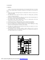
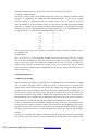
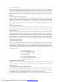
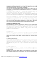
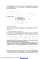
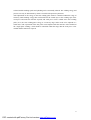
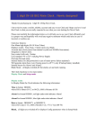
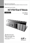
AP5K-C Precision AC Double-Pulse Spot Welding Machine
User’s Manual
Shenzhen Will-Best Electronics Co., Ltd
1
PDF created with pdfFactory Pro trial version www.pdffactory.com
Content
1. Introduction...................................................................................................................................3
1.1 Functions.............................................................................................................................3
1.2 Units of AP5K-C.................................................................................................................4
2. The Initial Installation and Adjustment of AP5K-C......................................................................7
2.1 Check of the complete set of AP5K-C ................................................................................7
2.2 Environmental Requirements of the Installation.................................................................7
2.3 The First Installation and Connection .................................................................................7
3. Welding Applications ..................................................................................................................10
3.1 Double-Spot Welding........................................................................................................10
3.2 Advantages of Double-Pulse Welding............................................................................... 11
3.3 Welding Parameters of AP5K-C ....................................................................................... 11
3.4 Applications and Adjustment of AP5K-C .........................................................................13
2
PDF created with pdfFactory Pro trial version www.pdffactory.com
1. Introduction
1.1 Functions
AP5K-C is the pneumatic double-independence pressure-adjustable double-pulse AC integral
precision spot welding machine with double welding spots. Its advantages can be described as
follows:
1) Control power supply: with integral design, the welding head is small in size and easy to be
installed and adjusted.
2) The double-pulse current output can effectively enhance the welding quality, particularly
suitable to welding clad materials.
3) The half-wave control can shorten the welding time, effectively reduce the thermal impact on
the work pieces and avoid discoloring and deforming.
4) The automatic mains voltage compensation can keep the welding quality from being
influenced by the fluctuation of the mains voltage.
5) The digital setting for the welding parameters is precise and can be easily adjusted.
6) Ten-set welding procedure record brings facilitations in production and application.
7) The precise welding pressure following mechanism can be used for adjusting the welding
pressure accurately and guarantee consistency of the welding.
8) The height of the welding head and the maximum stroke range can be adjusted so as to meet
requirements of different work pieces.
9) The independent pressure adjustable method of double welding spot can be used for
compensating the pressure to the individual welding spot so as to guarantee the consistency of
the welding strength of the two welding spots.
14
15
16
17
18
19
20
21
22
23
AP5K
WILL-BEST Co
GROUP No
WLD
SET
ENT
F1
ESC
F2
DATA
24
1
2
3
4
5
6
7
8
AIR Pa
9
25
26
27
28
10
ON
11
OFF
12
13
3
PDF created with pdfFactory Pro trial version www.pdffactory.com
1.2 Units of AP5K-C
AP5K-C adopts the integral design for the power controller and the welding head. The adjustment
of the welding functions centers on the front panel and rear panel of the power controller. The
front panel contains the welding head, parameter display and functional keys; the rear panel
mainly contains all kinds of connecting devices, fuse and cooling fan.
A. Functional units of the front panel
(1) Display for selections of the welding procedures and welding parameters
The display for selections of the welding procedures and welding parameters are composed of
three figures.
The left one displays the number of welding procedure, with displaying range of ten welding
procedures from 0 to 9.
The central one displays the space character‘——’ when at the “parameter setting”; it will not
display when at the “welding”.
The right one is the indicating bit for the welding parameters. When at the “parameter setting”, it
displays the item numbers of the parameters, with the range from 1 to 8; it will not display when at
the “welding”.
(2) [UP key for selections of the welding procedures and welding parameters ]
The UP key for selections of the welding procedures and welding parameters is a
double-functional key. When at the “welding”, it is the UP key for selections of the welding
procedures, as it is pressed for one time, the item number of the welding procedure will be
increased by ONE; when at the “parameter setting”, it is the UP key for selections of welding
parameters, as it is pressed for one time, the item number of the welding parameter will be
increased by ONE.
(3) [DOWN key for selections of the welding procedures and welding parameters]
The DOWN key for selections of the welding procedures and welding parameters is the
double-functional key. When at the “welding”, it is the DOWN key for selections of the welding
procedures, as it is pressed for one time, the item number of the welding procedure will be
decreased by ONE; when at the “parameter setting”, it is the DOWN key for selections of welding
parameters, as it is pressed for one time, the item number of the welding parameter will be
decreased by ONE.
(4) ENTER key for parameter setting state
AP5K-C has two working states: “Welding” and “Parameter setting”. When it is in the “Welding”,
press this key to enter into the “Parameter setting”.
(5) EXIT key for parameter setting state
AP5K-C has two work states: “Welding” and “Parameter setting”. When it is in the “Parameter
setting”, press this key to enter into the “Welding” and the latest alterations of the welding
parameters will be memorized.
(6) INCREASE key for welding parameters
When the welding machine is in the “Parameter setting”, this key can be used for altering the
selected welding parameter, as it is pressed, the currently displayed welding parameter will be
increased by ONE, and press and hold it for several seconds, the welding parameters will be
4
PDF created with pdfFactory Pro trial version www.pdffactory.com
increased rapidly.
(7)DECREASE key for welding parameters
When the welding machine is in the “Parameter setting”, this key can be used for altering the
selected welding parameter. As it is pressed, the currently displayed welding parameter will be
decreased by ONE, and press it without releasing for several seconds, the welding parameters will
be decreased rapidly.
(8) Display of the welding parameters
The Display of the welding parameters is composed of three figures. When the machine is in the
“Parameter setting”, it will display the value of the selected welding parameter; when in the
“Welding”, it displays the electric current value of the first welding pulse.
(9) Barometer
It is used for displaying the air pressure which drives the welding head.
(10) Air pressure regulating valve
It is used for adjusting the air pressure which drives the welding head.
(11) Power switch
It is used to connect or disconnect the working voltage of the power controller.
(12) Adjustable welding workbench
This welding work bench with adjustable height is used for placing the weld work pieces during
welding.
(13) Locking screws of the welding work bench
(14) Locknut for the welding head stroke
It is used for locking the stroke adjusting knob of the welding head.
(15) Adjusting knob of the welding stroke
It is used for adjusting and limiting the stroke length of the welding head.
(16) Adjusting knob of the welding pressure
It is used for adjusting the welding air pressure of the corresponding welding spot. It has two
knobs totally, namely the left welding air pressure adjusting knob and the right welding air
pressure adjusting knob.
(17) Cylinder
It is used for driving the welding head.
(18) Knob for adjusting the lowering speed of the welding head
It is used for adjusting the lowering speed of the welding head and shall be adjusted with “Knob
for adjusting the lifting speed of the welding head” at the same time. (It has been properly set
before the product is delivered).
(19) Knob for adjusting the lifting speed of the welding head
It is used for adjusting the lifting speed of the welding head and shall be adjusted with “Knob for
adjusting the lowering speed of the welding head” at the same time. (It has been properly set
before the product is delivered).
(20) Indicating LED for the parameter setting
This indicating LED will be lit when the welding machine is in the “Parameter setting.”
(21) Indicating LED for the Welding
This indicating LED will be lit when the welding machine is in the “Welding.”
(22) F2 reserving LED
It is used for the reserving function.
5
PDF created with pdfFactory Pro trial version www.pdffactory.com
(23) F1 reserving LED
It is used for the reserving function.
(24) Following mechanism for the welding pressure
(25) Clamp splice *2
It is used for clamping the welding rod tightly and adjusting the distance between two welding
rods.
(26) Welding rod*2
(27) Output welding cable*2
It is used for connections between the power controller and the welding head so as to provide the
current routing for welding.
(28)Welding power output terminals
29
30
FUSE
AP5K-A顶视图
31
34
32
35
33
36
B. Functional units of the rear panel
(29) Fuse tube base
(30) Input terminal base of the foot switch
It is used for connecting of the foot switch
(31) Reserved connector hole
(32) Input terminal of the power cable
This is the working voltage input cable, generally working voltage is single-phase
220VAC, and can also be set as single-phase 110VAC or 380VAC according to
requirements.
(33) Power cable
(34) Cooling fan
(35) Inlet of compressed air
It is used for connecting the external compressed air source.
(36) Filter of compressed air
It is used for filtering moisture in the external compressed air.
6
PDF created with pdfFactory Pro trial version www.pdffactory.com
2. The Initial Installation and Adjustment of AP5K-C
As AP5K-C applies the integral design of power and welding head, most of the work of
installation and adjustment has been finished before the product is delivered. Thus only some
simple on-site installation work is needed. Users can conduct the installation and adjustment
according to the following procedures so as to put the machine into operation.
2.1 Check of the complete set of AP5K-C
When AP5K-C is unpacked, the user shall check to see if it is intact. If any defects are found, the
user shall stop the installation and contact us promptly. The complete set of AP5K-BA includes:
(1) One AP5K-C integral welding control power
(2) One small-size foot switch
(3) One set of welding rods
(4) One installation base for the machine (optional)
(5) One packet of hexagon socket head cap screw
(6) One adjustable work bench.
2.2 Environmental Requirements of the Installation
The good working environment benefits the equipment in terms of reliability, stability and
life-span for the long term work. So the environment for installing the machine shall comply with
the following conditions:
(1) The place shall be clean, dry and dust-free.
(2) As the machine is somewhat heavy, it shall be installed on a plane and firm work bench.
(3) It shall have good heat emission conditions. Enough space shall be kept for placing the
machine. The distance between the two sides of the machine and the nearest baffle plate shall
be more than 15cm and the distance between the rear side and the nearest baffle plate shall be
more than 20cm.
(4) Make sure that there is no strong magnetic field in the place.
(5) The work power of the machine is 220 VAC (and can also be set as 110VAC as required). The
installation place must be able to supply stable AC power supply.
(6) The installation place must be able to supply stable compressed air source.
2.3 The First Installation and Connection
(1)Place the machine on suitable work bench
The “Installation base” of AP5K-C is an optional piece. The machine must be installed on a plane
and firm work bench. As shown in Figure 1, the operator shall first drill four holes on the work
bench and then tighten the machine with screws on the work bench.
7
PDF created with pdfFactory Pro trial version www.pdffactory.com
Rectangular Fixing Holes for the Machine*4;
AP5K-C Top View
(2) Connect the machine with AC power
The working power of AP5K-C is single phase 220VAC, 50/60Hz (It has been properly set before
delivery) and can be set as single-phase 110VAC or 380VAC 50/60Hz according to requirements.
Insert the plug of “power cable” into the conforming socket close to the machine. Make sure the
plug is properly inserted and the connection is reliable and not loose.
(3) Connect the AP5K-C with the compressed air source
Pull out the adjusting knob of the “air pressure adjusting valve” first and then rotate it
counter-clockwise till it can’t be rotated. Then push back the knob. Connect the external air source
to the inlet of the compressed air on the compressed air filter. Make sure they are properly
connected. Pull out the adjusting knob of the “air pressure adjusting valve” and rotate it clockwise
till “barometer” shows the air pressure is 2.0kg.
(4) Tighten the “welding rod” to the “clamp splice” and adjust it properly
Loosen the tightening screws for the welding rod at the “clamp splice” and insert the welding rod
into the clamping hole. As shown in the Figure, adjust the distance between the two welding rods
and their height so as to keep the two welding rod at the same level naturally and the distance
between the two welding spots comply with the requirements of the actual welding work.
Tightening screws
Clamp splice
Weld rod.
8
PDF created with pdfFactory Pro trial version www.pdffactory.com
(5) Adjustment of the stroke length of the AP5K-C welding head
The adjustment of the stroke length of the AP5K-C welding head will directly affect the welding
pressure and the welding results. So it shall be properly adjusted. By means of adjusting the height
of the “adjustable welding work bench”, the height between the welding rod and the work piece to
be welded can be less than 3mm before the welding rod is pressed down (such height can be
minimized so long as the operations are not affected). Then tighten “locking screw of the welding
work bench”.
Original place of the welding head
Battery
Adjustable welding work bench
Locking screw of the welding work bench
Turn on the “power switch” of the machine and press “ENTER” key for parameter setting so as to
make the machine run under the “parameter setting” state. Step on the “foot switch” to press down
the welding head. Adjust the “adjusting knob of the welding head stroke” so that the height of the
“welding rod” is 2 to 3mm lower than the work piece to be welded after the welding is pressed
down. As shown in the Figure, then tighten “locknut for the welding head stroke”.
Position after the welding head is pressed
down
Spot needs to be welded
Battery adjustable work bench
Locking screw for the welding work bench
height
(6) Setting welding pressure
Rotate the “adjusting knob of the welding pressure” to adjust the welding pressure for each
welding rod and make it at the middle part of the adjustable pressure range. (For details of
9
PDF created with pdfFactory Pro trial version www.pdffactory.com
adjusting the welding pressure, please refer to the section of Welding Applications).
(7) Setting welding parameter
Turn on the “power switch” of the machine and use the “UP key for welding procedure/welding
parameter” or ”DOWN key for welding procedure/welding parameter” to select the “0” welding
procedure (taking “0” welding procedure for example); press the key of “parameter setting” to
make the machine be in the “parameter setting”; use the “UP key for welding procedure/welding
parameter” or ”DOWN key for welding procedure/welding parameter” to select different welding
parameters and use the “INCREASE key for welding parameters” or the “DECREASE key for
welding parameters” to set the different welding parameters as follows:
0-1:
10
0-2:
2
0-3:
1
0-4:
0
0-5:
0
0-6:
0
0-7:
5
After setting properly, press the “EXIT key for parameter setting” to make the machine return to
the “Welding” state.
(8) Welding test
Place the work piece onto the “adjustable welding work bench” and properly align the “welding
rod” to the desired welding spot. Then step down the foot switch so as to make “welding rod” be
pressed on the work piece and conduct the welding after the unit is powered on. Adjust the
welding energy (increase or decrease the welding energy of 0-3) till the work piece is welded
firmly. (For details of adjusting the welding parameters and pressure, please refer to the section of
Welding Applications).
3. Welding Applications
3.1 Double-Spot Welding
When the double-spot welding is conducted, the two independently pressure-adjustable “welding
rods” of AP5K-C will apply certain welding pre-pressure on the work piece to guarantee the
reliable holmic contact between the work pieces being welded. Then electric discharge with the
big volume current will be applied on the work pieces being welded by the two “welding rods” so
that the holmic contact can generate large and instant resistance heat. Then the contact area
between the work pieces being welded is heated to the softened plastic-like state. At the same time,
certain upsetting force is applied on the welding spot so that the metal atoms of two work pieces
being welded can be infiltrated with each other and the good binding force can be achieved.
As the two independent pressure-adjustable welding rods apply the pressure and discharge on the
work pieces being welded, two holmic contacts will be formed on the discharging return circuit.
Thus the electric current will pass these two points when welded with discharge and the resistance
heat will be generated on these two contacts simultaneously. In this way, the two-spot welding is
realized.
Therefore, the consistent and reliable resistance heat must be produced to obtain the good welding
spot. And the generation of such resistance heat depends on good holmic contact and the steady
10
PDF created with pdfFactory Pro trial version www.pdffactory.com
electric current for welding. When the voltage output for welding maintains a certain level, if the
resistance of the contact point is too high, the resistance heat generated at this point will be low,
which may lead to weak welding. Meanwhile, if the resistance at the contact point is too low,
much more current will be needed to produce the equal amount of resistance heat. Furthermore, if
the electric current needed can’t be supplied, the phenomena of weak welding will appear. To
realize good welding, apart from the energy needed, there are other two aspects that are important
and can’t be ignored: one is the adjustment of the welding pressure, the other is the surface status
between the work pieces to be welded (foe example smoothness of the combined surface, or if
there has oil stain, oxides, etc.) When the welding strength of the two welding spots is inconsistent,
proper compensation shall be made by means of adjusting the different welding pressures of the
two welding rods so that the strength of the two welding spots can keep consistent. This is also
one of the advantages of the double independent pressure-adjustable mechanism.
3.2 Advantages of Double-Pulse Welding
Under the same welding parameters, the inconsistency of the surface conditions of the welding
work pieces will directly lead to the inconsistent quality of the welding spots after the welding is
finished. Particularly, when some of the work pieces have coated layers, oxides or oil stains, such
phenomena will be more obvious, which may affect the rate of finished products of the welding
work pieces.
Such phenomena are caused by the coated layers and the oxidized layers, which greatly increase
the contact resistance at the welding spot, prevent the consistent and large current passages from
being formed during welding and reduce the resistance heat at the welding spot, which may result
in weak welding. The double-pulse welding can effectively reduce the instabilities of welding
quality which are caused by the inconsistency of the surface conditions of the work pieces. The
double-pulse welding has unexampled advantages when compared with the traditional
single-pulse welding as it is composed of two pulses: the first pre-welding pulse and the second
welding pulse, which can make the discharge to the same welding spot for two times. When the
welding rod is pressed down, the first pulse will make the discharge with low current to break
down the coated layer, oxidized layer and other things of the work piece surface, get the same
cleaning condition of the welding spot and expose the materials to be welded. Thus a relatively
consistent contact resistance can be obtained for the work piece so as to supply the second
discharge welding pulse with a good discharge return circuit. After that, a high pulse welding
current (the second pulse) will be output to realize better welding results. This welding method
can efficiently enhance the stability and consistency of the welding.
3.3 Welding Parameters of AP5K-C
AP5K-C is a precise double-spot and double-pulse AC welding machine. This machine can store
ten sets of welding procedures from 0 to 9 and each set of welding parameter includes the welding
parameters from 1#~7#. Such a parameter must be adjusted in the “parameter setting” state. The
different parameters are shown in details in the following Figure:
11
PDF created with pdfFactory Pro trial version www.pdffactory.com
One digit for displaying the welding procedure
number
One
digit
for
displaying
the space
character
One digit for displaying the parameter
number
INCREASE
key
for
welding
key
for
welding
procedure/parameter
DECREASE
procedure/parameter
ENTER key for parameter setting
state
EXIT key for parameter setting
state
DECREASE
key
for
welding
INCREASE
key
for
welding
parameters
parameters
Three-digit display of the welding
parameters
Parameter3#
Parameter1#
Parameter7#
Parameter2#
Parameter6#
Parameter4#
Parameter5#
One welding process
(1) Parameter1#
Parameter1# indicates the pre-pressing time.
As shown in the Figure, the pre-pressing time is the time between that the welding head begins to
be pressed down and that the welding rod is firmly pressed by the work piece. When the machine
is in the “parameter setting”, alterations can be made using the “INCREASE key for parameter
adjustment” or “DECREASE key for parameter adjustment”. The adjustment range is between ‘0
to 0.99’ second, with the minimum adjustment precision of 0.01 second.
(2) Parameter2#
Parameter2# indicates the first pulse time.
As shown in the Figure, the first pulse time is the discharge time of the first pulse. When the
machine is in the “parameter setting”, alterations can be through the “INCREASE key for
12
PDF created with pdfFactory Pro trial version www.pdffactory.com
parameter adjustment” or “DECREASE key for parameter adjustment”. The adjustment range is
between ‘0 to 0.99’ second, with the minimum adjustment precision of 0.01 second.
(3) Parameter3#
Parameter3# indicates the first pulse energy.
As shown in the Figure, first pulse energy is the unit discharge energy of the first welding pulse,
which is the discharge energy of 0.01 second. When the machine is in the “parameter setting”,
alterations can be through the “INCREASE key for parameter adjustment” or “DECREASE key
for parameter adjustment”. The adjustment range is between ‘0 to 0.99’ second, with the minimum
adjustment precision of ’1%’.
(4) Parameter4#
Parameter4# indicates the interval time.
As shown in the Figure, the interval time is the time between the end of the first pulse discharge
and the second pulse discharge. When the machine is in the “parameter setting”, alterations can be
through the “INCREASE key for parameter adjustment” or “DECREASE key for parameter
adjustment”. The adjustment range is between ‘0 to 0.99’ second, with the minimum adjustment
precision of 0.01 second.
(5) Parameter5#
Parameter5# indicates the second pulse time.
As shown in the Figure, the second pulse time is the time when the second pulse makes discharge.
When the machine is in the “parameter setting”, alterations can be through the “INCREASE key
for parameter adjustment” or “DECREASE key for parameter adjustment”. The adjustment range
is between ‘0 to 0.99’ second, with the minimum adjustment precision of 0.01 second.
(6) Parameter6#
Parameter6# indicates the second pulse energy.
As shown in the Figure, second pulse energy is the unit discharge energy of the second welding
pulse, which is the discharge energy of 0.01 second. When the machine is in the “parameter
setting”, alterations can be through the “INCREASE key for parameter adjustment” or
“DECREASE key for parameter adjustment”. The adjustment range is between ‘0 to 0.99’ second,
with the minimum adjustment precision of ’1%’.
(7) Parameter7#
Parameter7# indicates the dwell time.
As shown in the Figure, the pressure reserve time means that, after the welding with discharge is
finished, some certain pressure is still maintained in the course of cooling for the welding spot to
enhance the strength of the welding spot. When the machine is in the “parameter setting”,
alterations can be through the “INCREASE key for parameter adjustment” or “DECREASE key
for parameter adjustment”. The adjustment range is between ‘0 to 0.99’ second, with the minimum
adjustment precision of 0.01 second.
3.4 Applications and Adjustment of AP5K-C
3.4.1 Application of Single-Pulse Welding
When some thin sheets with good surface conditions (without coated layer, or relatively clean),
such as pure nickel, nickel plated steel band, etc. need to be welded, the single-pulse welding can
be used to increase the welding speed. This adjustment takes battery welding as example and use
the “welding procedure1#”. The adjustment procedures can be described as follows:
13
PDF created with pdfFactory Pro trial version www.pdffactory.com
(1) Setting air pressure
Connect the machine with the external compressed air source, pull out the “air pressure adjusting
valve” from the locking position and then rotate the “air pressure adjusting valve” (clockwise to
decrease the pressure and counter-clockwise to increase the pressure). When the barometer
indicates that the air pressure is 2.0kg, push the “air pressure adjusting valve” back to the locking
position.
(2) Adjusting the welding rod position
After the cylinder of the welding head is connected with 2.0 kg pressure, it will move to the
uppermost position. Loosen the locking screws of “clamp splice” to make the lower end of the
welding rod extend out about 20mm from the “clamp splice”; Rotate the two eccentric welding
rods to adjust the spacing interval of the two pins to 1.5mm (0.06in). Then tighten the locking
screws.
(3) Setting welding head stroke
Place the work piece to be welded on the “adjustable work bench” and adjust its height to make
the weld battery keep the distance of 2mm to 3mm from the lowest end of the welding rod after
the nickel band is put.
Turn on the power switch of the machine and press the “ENTER key for parameter setting state”
to make the machine be in the “parameter setting” state. Step on the foot switch to lower down the
welding head. By means of the adjusting knob of the welding head stroke, as shown in the Figure,
make the height of the welding rod about 2mm lower than the battery to be welded after the
welding head is pressed down. After the adjustment, tighten the adjusting knob of the welding
head stroke with the locknut.
(4) Setting welding parameters
Turn on the power switch of the machine, use the “UP or DOWN key for selecting the welding
procedure and welding parameters” to select the welding procedure0# and then press down the
“ENTER key for parameter setting state” to make the machine be in the “parameter setting”. This
welding adjustment adopts welding procedure0# and the setting of the welding parameters can be
described as follows:
0-1(Pre-pressing time)
:8
0-2(First welding pulse time)
:2
0-3(First welding pulse energy)
:5
0-4(Interval time)
:0
0-5(Second welding pulse time)
:0
0-6(Second welding pulse energy) : 0
0-7(Pressure reserve time)
:2
(5) Setting of the welding pressure
Adjust the two “knobs of adjusting the welding pressure” to the middle of the adjustable range
(rotate it clockwise to increase the welding pressure and counter-clockwise to decrease the
welding pressure).
(6) Trial welding and adjusting welding parameters
The work piece to be welded should be put under the welding head and aligned properly. Step
down the foot switch to conduct the trial welding. If the work piece is not firmly welded, increase
the welding energy (increase the Parameters of ‘0-3’#) till it can be firmly welded.
*If the color of the welding spot changes very obviously, set the “0-2” first welding pulse time as
14
PDF created with pdfFactory Pro trial version www.pdffactory.com
1 to reduce the welding time. Then readjust the welding energy till the work piece can be firmly
welded. (It is recommended that adjustment of the welding energy shall be begun with a small
value as indicated by the number, then increase the value gradually.)
*If the work piece can’t be firmly welded even though the welding energy is relatively large (e.g.
more than 90), you can appropriately increase the welding time (Parameter “0-2” #) and decrease
the welding pressure.
*If the firmness of the two welding spots is inconsistent, make compensations through fine
adjustment for the welding pressure of the welding rod at the weak welding spot.
*Increasing the welding pressure will help reduce sparks and splashing. But it will increase the
possibilities that the work piece may be deformed after it is welded and the welding energy needs
to be increased correspondingly. Low welding pressure supported with relatively small welding
energy can realize firm welding and the welded work piece is not easy to be deformed. But if the
welding pressure is not sufficient, it may cause much splashing or even the welding fire. So the
adjustment of the welding pressure shall be controlled within the range that the welding reliability
can be realized and the welding sparks and splashing can be maximally reduced. The welding
energy and pressure can only be determined by means of careful and repeated experiments.
3.4.2 Application of Double-Pulse Welding
It is recommended that, if the surface conditions are not consistent or not good enough (without
coated layers or oxidized layers, or the surface is not plane, e.g. with surface voids), or welding
results are not ideal after the single-pulse welding, the double-pulse welding can be used. This
adjustment takes battery welding as example and use the “welding procedure1#”. The adjustment
procedures can be described as follows:
(1)Setting air pressure
Connect the machine with the external compressed air source, pull out the “air pressure adjusting
valve” from the locking position and then rotate the “air pressure adjusting valve” (clockwise to
decrease the pressure and counter-clockwise to increase the pressure). When the barometer
indicates that the air pressure is 2.0kg, push the “air pressure adjusting valve” back to the locking
position.
(2) Adjusting welding rod position
After the cylinder of the welding head is connected with 2.0 KG pressure, it will move to the
uppermost position. Loosen the locking screws of “clamp splice” to make the lower end of the
welding rod extend out about 20mm from the “clamp splice”; Rotate the two eccentric welding
rods to adjust the spacing interval of the two pins to 1.5mm (0.06in). Then tighten the locking
screws.
(3) Setting welding head stroke
Place the work piece to be welded on the “adjustable work bench” and adjust its height to make
the weld battery keep the distance of 2mm to 3mm from the lowest end of the welding rod after
the nickel band is put.
Turn on the power switch of the machine and press down the “ENTER key for parameter setting
state” to make the machine be in the “parameter setting”. Step on the foot switch to lower down
15
PDF created with pdfFactory Pro trial version www.pdffactory.com
the welding head. By means of the adjusting knob of the welding head stroke, as shown in the
Figure, make the height of the welding rod about 2mm lower than the battery to be welded after
the welding head is pressed down. After the adjustment, tighten the adjusting knob of the welding
head stroke with the locknut.
(4) Setting welding parameters
Turn on the power switch of the machine, use the “UP or DOWN key for selecting the welding
procedure and welding parameters” to select the welding procedure1# and then press down the
“ENTER key for parameter setting state” to make the machine be in the “parameter setting”. This
welding adjustment uses the welding procedure1# and the setting of the welding parameters can
be described as follows:
1-1(Pre-pressing time)
:8
1-2(First welding pulse time)
:2
1-3(First welding pulse energy)
:2
1-4(Interval time)
:10
1-5(Second welding pulse time)
:2
1-6(Second welding pulse energy) : 4
1-7(Pressure reserve time)
:2
(5.) Setting welding pressure
Adjust the two “knobs of adjusting the welding pressure” to the middle of the adjustable range
(rotate it clockwise to increase the welding pressure and counter-clockwise to decrease the
welding pressure).
(6) Trial welding and adjusting welding parameters
Put the work piece to be welded under the welding head and align its position properly. Then step
down the foot switch to conduct the trial welding. If the work piece is not firmly welded, increase
the second pulse energy (increase the Parameters of ‘1-6’#) and the first welding energy as well
(Increase the Parameters of ‘1-3’#. Normally, the energy of the first welding pulse shall be
adjusted to1/3~1/2 of the second welding pulse) till it can be firmly welded.
*If the color of the welding spot changes very obviously, set the “0-5” second welding pulse time
as 1 to reduce the welding time. Then readjust the welding energy till the work piece can be firmly
welded. (It is recommended that adjustment of the welding energy shall be begun with a small
value as indicated by the number, then increase the value gradually.)
*If the work piece can’t be firmly welded even though the welding energy is relatively large (e.g.
more than 90), you can appropriately increase the welding time and decrease the welding pressure.
*If the firmness of the two welding spots is inconsistent, make compensations through fine
adjustment for the welding pressure of the welding rod at the weak welding spot.
*Increasing the welding pressure will help reduce the sparks and splashing. But it will increase the
possibilities that the work piece may deform after it is welded and the welding energy needs to be
increased correspondingly. Low welding pressure supported with relatively small welding energy
can realize firm welding and the welded work piece is not easy to be deformed. But if the welding
pressure is not sufficient, it may cause much splashing or even the welding fire. So the adjustment
of the welding pressure shall be controlled within the range that the welding reliability can be
16
PDF created with pdfFactory Pro trial version www.pdffactory.com
realized and the welding sparks and splashing can be maximally reduced. The welding energy and
pressure can only be determined by means of careful and repeated experiments.
*The adjustment of the energy of the first welding pulse shall be controlled within the range of
relatively small welding energy that can break down the coated layer at the welding spot of the
work piece and make the material exposed, and work piece can be welded at the first welding
pulse (if so, the first welding pulse energy is excessively large and it needs to be adjusted to a
small value). The experiment of the first pulse can be adjusted with the reference of the method of
the “single-pulse welding”, which shall be controlled within the range that the work piece is not
welded and the material is exposed.
17
PDF created with pdfFactory Pro trial version www.pdffactory.com