1
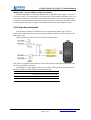
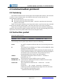
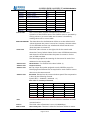
北京博创兴盛机器人技术有限公司 UPTECH Robotics
proMotion CDS55xx
User Manual
Doc. Ver.
Update
Rev.
Authorized by
Remarks
1.0
2010-3-22
何裕德
徐俊辉
1.1
2010-3-27
计海锋
徐俊辉
Add Chapter 5
1.2
2010-4-22
何裕德
1.3
2010-8-17
Cid
徐俊辉
Revise
TEL:+86-010-8211-4870, +86-010-8211-4887 FAX:Ext.828
Page 1 of 21
http://robot.up-tech.com
北京博创兴盛机器人技术有限公司 UPTECH Robotics
Thanks for purchasing ProMotion CDS55xx series robot servo. This document is
currently a trial version. If you have any errors or suggestion, please send Email to us or
post at our web forum:
http://robot.up-tech.com/bbs/index.asp?boardid=1
Service dept.:86-10-82114870/4887/4890
Service Email:[email protected]
TEL:+86-010-8211-4870, +86-010-8211-4887 FAX:Ext.828
Page 2 of 21
http://robot.up-tech.com
北京博创兴盛机器人技术有限公司 UPTECH Robotics
1 General Introduction
1.1 Features and profile
ProMOTION CDS series robot servo is a robot actuator which integrated motor, sensor,
servo algorithm and serial bus port. It’s an ideal actuator for small robots and other simple
position control equipment.
l High torque:
n 16Kgf.cm (CDS5516/5500)
n 6Kgf.cm (CDS5506)
l High speed:
n 0.18s/60°(CDS5516/5500)
n 0.16s/60°(CDS5506)
l DC 6.0V~16V power supply
l 0.32° position resolution
l Double-side output shaft
l Alloy gearbox, dual ball-bearing (CDS5516/5500)
l Resin gearbox, dual ball-bearing (CDS5516/5500)
l Rubber O-ring at output shaft
l Position control range: 0-300°
l 1023 step speed control, continuous rotation
l Up to 30-50 servos serial bus link
l 1Mbps High baud rate
l 250Hz servo refresh rate
l Position/Temperature/Voltage/Speed feedback
l Interface and protocol mostly compatible to Robotis Dynamixel AX12+
CDS55xx robot servo uses advanced control algorithm and high-speed micro
controller, with fast response and high position accuracy.
The CDS55xx robot servo integrated a continuous rotation position sensor with 330°
measure range for position control, and it enables the continuous rotation.
The CDS55xx use a half-duplex UART as communication bus port. User can assign a
address for each servo, and control single servo or broadcast instruction to each servo.
The communication protocol of CDS55xx is opened to users; please refer to this
document. The bus port is compatible to Robotis’ Dynamixel AX12+, and the protocol is
mostly compatible to it.
There are two work modes of CDS55xx: Position mode and gear motor mode. User
can change mode with instructions.
The profile and mount flange is compatible to most off-the-shelf standard R/C servos.
Please refer to the “CDS55xx robot servo Datasheet” for more Details.
TEL:+86-010-8211-4870, +86-010-8211-4887 FAX:Ext.828
Page 3 of 21
http://robot.up-tech.com
北京博创兴盛机器人技术有限公司 UPTECH Robotics
1.2 Electrical Connection
1.2.1 Bus port
The bus port and typical connection diagram of proMOTION CDS55xx series robot
servo is as shown below:
1.2.2 Serial connection
CDS55xx robot servo uses a half-duplex UART bus for serial communication.
There are two main methods to connect a CDS55xx servo:
Method One:Control CDS55xx via a UP-debugger (or Robotis’ USB2Dynamixel)
The UP-debugger will be recognized as a virtual RS-232 serial port device. User can
send instruction packet with RS-232 communication software(Such as Hyper Terminal or
UPTECH Robotics’ RobotServoTerminal), the instruction packet will be send to the
UP-debugger and transferred to the CDS55xx robot servo. The servo will execute the
instruction packet and return a response packet.
The RobotServoTerminal software is designed for tuning or setting up CDS55xx robot
servos. This method is a convenient method to set up and tune your servos. If you use a
PC as the robot’s main controller, this method enables you to control servos with only a
UP-debugger board.
TEL:+86-010-8211-4870, +86-010-8211-4887 FAX:Ext.828
Page 4 of 21
http://robot.up-tech.com
北京博创兴盛机器人技术有限公司 UPTECH Robotics
Method Two:Control CDS55xx via Microcontroller
Method One needs a PC running Windows XP or Windows Vista system. If you do
not want to use PC, you can design a microcontroller to interface the CDS55xx servos. You
only need a UART port on the MCU, and make little interface circuit. the sub paragraph
1.2.3 gives a sample interface schematic using a AVR MCU’s UART port. Chapter 5 of this
document gives a sample controller, including schematic and some sample C code.
1.2.3 Interface schematic
The serial bus interface of CDS55xx servo is a half-duplex UART, with 3 wires. To
control the CDS55xx servos, the main controller needs to convert its UART signals to the
half duplex type.
The schematic of a CDS55xx servo interface is shown below.
The power is supplied to the CDS55xx servo from the main controller through Pin 1 and
Pin 2 of the Molex3P connector.
The direction of data signals on the TTL level MCU_TXD and MCU_RXD depends on
the MCU_TXEN and MCU_RXEN level as the following.
MCU_TXEN
MCU_RXEN
Status
1
0
the signal from MCU_TXD is output as SIG
0
1
the signal from SIG is input as MCU_RXD
0
0
high-impedance
TEL:+86-010-8211-4870, +86-010-8211-4887 FAX:Ext.828
Page 5 of 21
http://robot.up-tech.com
北京博创兴盛机器人技术有限公司 UPTECH Robotics
2 Communication protocol
2.1 Summary
The CDS55xx serial bus has a master device and multiple slave devices. The controller
(or the PC) acts as master device, the CDS55xx servos act as slave devices. The
communication sequence is:
n The master sends an instruction packet;
n The slave receive the instruction packet,execute it, and then send an answer
packet to the master.
There are two types of packets; the “Instruction Packet” (sent from the main controller
to the servos) and the “Status Packet” (sent from the servos to the main controller.)
There can be multiple CDS55xx servos on the bus; each servo should be assigned an
unique ID. The instruction packet contains the ID info, only the corresponding servos will
response the instruction packet when other servos will ignore them.
2.2 Instruction packet
Instruction packet format:
HEADER
ID
LENGTH
INSTRUCTION
PARAMETER
CHECK SUM
0XFF 0XFF
ID
Length
Instruction
Parameter1 ... N
0x??
The meanings of each packet byte definition are as the following.
Header:
ID:
LENGTH:
INSTRUCTION:
PARAMETER0…N
CHECK SUM
two 0xFF in sequence indicates the start of a incoming instruction
packet.
The unique ID of a CDS55xx unit. There are 254 available ID values,
ranging from 0X00 to 0XFD.
Broadcasting ID ID 0XFE is the Broadcasting ID which indicates all
of the connected CDS55xx units. Packets sent with this ID apply to
all CDS55xx units on the network. Thus packets sent with a
broadcasting ID will not return any status packets.
The length of the packet where its value is “Number of
parameters (N) + 2”
The instruction for the CDS55xx servo to perform.
Used if there is additional information needed to be sent other
than the instruction itself.
The computation method for the ‘Check Sum’ is as the
following.
Check Sum = ~ (ID + Length + Instruction + Parameter1 + ...
Parameter N).If the calculated value is larger than 255, the lower
byte is defined as the checksum value.
~ represents the NOT logic operation.
TEL:+86-010-8211-4870, +86-010-8211-4887 FAX:Ext.828
Page 6 of 21
http://robot.up-tech.com
北京博创兴盛机器人技术有限公司 UPTECH Robotics
2.3 Status packet
The Status Packet is the response packet from the CDS55xx servos to the Main
Controller after receiving an instruction packet. The structure of the status packet is as the
following.:
HEADER
ID
LENGTH
ERROR
PARAMETER
CHECK SUM
0XFF 0XFF
ID
Length
Status
Parameter1 ...Parameter N
Check Sum
The meanings of each packet byte definition are as the following.
HEADER
The two 0XFF bytes indicate the start of the packet.
ID
The unique ID of the CDS55xx unit returning the packet. The initial
value is set to 1.
LENGTH
The length of the packet where its value is “Number of
parameters (N) + 2”
ERROR
The byte representing errors sent from the CDS55xx unit. The
meaning of each bit is as the following.
BIT
Name
Details
BIT7
0
---
BIT6
Instruction Error
Set to 1 if an undefined instruction is sent or an action instruction is
sent without a Reg_Write instruction.
BIT5
Overload Error
Set to 1 if the specified maximum torque can't control the applied
load.
BIT4
Checksum Error
Set to 1 if the checksum of the instruction packet is incorrect.
BIT3
Range Error
Set to 1 if the instruction sent is out of the defined range.
BIT2
Overheating
Set to 1 if the internal temperature of the CDS55xx unit is above the
Error
operating temperature range as defined in the control table.
BIT1
Position
Limit
Error
BIT0
Input
Error
PARAMETER0…N
CHECK SUM
Set as 1 if the Goal Position is set outside of the range between CW
Angle Limit and CCW Angle Limit.
Voltage
Set to 1 if the voltage is out of the operating voltage range as defined
in the control table.
Used if additional information is needed.
The computation method for the ‘Check Sum’ is as the
following.
Check Sum = ~ (ID + Length + Instruction + Parameter1 + ...
Parameter N)
If the calculated value is larger than 255, the lower byte is defined
as the checksum value.
~ represents the NOT logic operation.
2.4 Instruction Set
The following Instructions are available.
TEL:+86-010-8211-4870, +86-010-8211-4887 FAX:Ext.828
Page 7 of 21
http://robot.up-tech.com
北京博创兴盛机器人技术有限公司 UPTECH Robotics
Instruction
Function
Value
Number
of
parameter
PING
No action. Used for obtaining a Status Packet
0x01
0
READ DATA
Reading values in the Control Table
0x02
2
WRITE DATA
Writing values to the Control Table
0x03
Not less than 2
REG WRITE
Similar to WRITE_DATA, but stays in standby
0x04
Not less than 2
the
0x05
0
Changes the control table values of the
0x06
0
0x83
Not less than 4
mode until the ACION instruction is given
ACTION
Triggers
the
action
registered
by
REG_WRITE instruction
RESET
CDS55xx servos to the Factory default values
SYNC WRITE
Used for controlling multiple CDS55xx servos
simultaneously
2.4.1 WRITE DATA
Function:
To write data into the control table of the CDS55xx servo
Length:
N+3 (N is the number of data to be written)
Instruction:
0X03
Parameter1:
Starting address of the location where the data is to be written
Parameter2:
1st data to be written
Parameter3:
2nd data to be written
Parameter N+1:
Nth data to be written
Example 1
Setting the ID of a connected CDS55xx servo to 1
Write 1 to address 3 of the control table. The ID is transmitted
using the Broadcasting ID(0xFE).
Instruction Packet: 0XFF 0XFF 0XFE 0X04 0X03 0X03 0X01 0XF6
HEADER
ID
LENGTH
NSTRUCTION
PARAMETERS
CHECKSUM
0XFF 0XFF
0XFE
0X04
0X03
0X03 0X01
0XF6
Because it was transmitted with a Broadcast ID (0XFE), no status packets are returned.
2.4.2 READ DATA
Read data from the control table of a CDS55xx servo
0X04
Instruction
0X02
Parameter1
Starting address of the location where the data is to be read
Parameter2
Length of the data to be read
Example 2
Reading the internal temperature of the CDS55xx servo with an ID
of 1
Read 1 byte from address 0x2B of the control table.
Instruction Packet:0XFF 0XFF 0X01 0X04 0X02 0X2B 0X01 0XCC
Function
Length
HEADER
ID
LENGTH
NSTRUCTION
PARAMETERS
CHECKSUM
0XFF 0XFF
0X01
0X04
0X02
0X2B 0X01
0XCC
The returned Status Packet will be as the following.
Status Packet : 0XFF 0XFF 0X01 0X03 0X00 0X20 0XDB
TEL:+86-010-8211-4870, +86-010-8211-4887 FAX:Ext.828
Page 8 of 21
http://robot.up-tech.com
北京博创兴盛机器人技术有限公司 UPTECH Robotics
HEADER
ID
LENGTH
NSTRUCTION
PARAMETERS
CHECKSUM
0XFF 0XFF
0X01
0X03
0X00
0X20
0XDB
The data read is 0x20. Thus the current internal temperature of the CDS55xx servo
is approximately 32°C (0X20).
2.4.3 REG WRITE
Function
Length
Instruction
Parameter1
Parameter2
Parameter3
Parameter N+1
The REG_WRITE instruction is similar to the WRITE_DATA
instruction, but the execution timing is different. When the
Instruction Packet is received the values are stored in the Buffer
and the Write instruction is under a standby status. At this time, the
Registered Instruction register (Address 0x2C) is set to 1. After the
Action Instruction Packet is received, the registered Write
instruction is finally executed.
N+3 (N is the number of data to be written)
0X04
Starting address of the location where the data is to be written
1st data to be written
2nd data to be written
Nth data to be written
2.4.4 ACTION
Function
Length
Instruction
Parameter
Broadcasting
Triggers the action registered by the REG_WRITE instruction
0X02
0X05
NONE
The ACTION instruction is useful when multiple CDS55xx servos
need to move simultaneously. When controlling multiple CDS55xx
servo units, slight time delays can occur between the 1st and last
units to receive an instruction. The CDS55xx servo handles this
problem by using the ACTION instruction.
The Broadcast ID (0XFE) is used when sending ACTION instructions
to more than two CDS55xx servos. Note that no packets are
returned by this operation.
2.4.5 PING
Does not command any operations. Used for requesting a status
packet or to check the existence of a CDS55xx servo with a specific
ID.
Length
0X02
Instruction
0X01
Parameter
NONE
Example 3
Obtaining the status packet of the CDS55xx servo with an ID of 1
Instruction Packet : 0XFF 0XFF 0X01 0X02 0X01 0XFB
Function
HEADER
ID
LENGTH
NSTRUCTION
TEL:+86-010-8211-4870, +86-010-8211-4887 FAX:Ext.828
Page 9 of 21
PARAMETERS
http://robot.up-tech.com
北京博创兴盛机器人技术有限公司 UPTECH Robotics
0XFF 0XFF
0X01
0X02
0X01
0XFB
The returned Status Packet is as the following
Status Packet : 0XFF 0XFF 0X01 0X02 0X00 0XFC
HEADER
ID
LENGTH
NSTRUCTION
PARAMETERS
0XFF 0XFF
0X01
0X02
0X00
0XFC
Regardless of whether the Broadcasting ID is used or the Status Return Level (Address
16) is 0, a Status Packet is always returned by the PING instruction.
2.4.6 RESET
Changes the control table values of the CDS55xx servo to the
Factory Default Value settings
Length
0X02
Instruction
0X06
Parameter
NONE
Example 4
Resetting the CDS55xx servo with an ID of 0
Instruction Packet : 0XFF 0XFF 0X00 0X02 0X06 0XF7
Function
HEADER
ID
LENGTH
NSTRUCTION
PARAMETERS
0XFF 0XFF
0X00
0X02
0X06
0XF7
The returned Status Packet is as the following
Status Packet : 0XFF 0XFF 0X00 0X02 0X00 0XFD
HEADER
ID
LENGTH
NSTRUCTION
PARAMETERS
0XFF 0XFF
0X00
0X02
0X00
0XFD
Note the ID of this CDS55xx servo is now changed to 1 after the RESET instruction
2.4.7 SYNC WRITE
Function
ID
Length
Instruction
Parameter1
Parameter2
Parameter3
Parameter4
Parameter5
Used for controlling many CDS55xx servos at the same time. The
communication time decreases by the Synch Write instruction since
many instructions can be transmitted by a single instruction.
However, you can use this instruction only when the lengths and
addresses of the control table to be written to are the same. Also,
the broadcasting ID needs to be used for transmitting.
0XFE
(L + 1) * N + 4 (L: Data length for each CDS55xx servo, N: The
number of CDS55xx servos)
0X83
Starting address of the location where the data is to be written
The length of the data to be written (L)
The ID of the 1st CDS55xx servo
The 1st data for the 1st CDS55xx servo
The 2nd data for the 1st CDS55xx servo Data for the 1st CDS55xx
servo
…
Parameter L+3
Parameter L+4
The Lth data for the 1st CDS55xx servo
The ID of the 2nd CDS55xx servo
TEL:+86-010-8211-4870, +86-010-8211-4887 FAX:Ext.828
Page 10 of 21
http://robot.up-tech.com
北京博创兴盛机器人技术有限公司 UPTECH Robotics
The 1st data for the 2nd CDS55xx servo
The 2nd data for the 2nd CDS55xx servo Data for the 2nd CDS55xx
servo
Parameter L+5
Parameter L+6
…
The Lth data for the 2nd CDS55xx servo
Parameter 2L+4
….
Setting the following positions and velocities for 4 CDS55xx servos
CDS55xx servo with an ID of 0: to position 0X010 with a speed of
0X150
CDS55xx servo with an ID of 1: to position 0X220 with a speed of
0X360
CDS55xx servo with an ID of 2: to position 0X030 with a speed of
0X170
CDS55xx servo with an ID of 0: to position 0X220 with a speed of
0X380
Instruction Packet : 0XFF 0XFF 0XFE 0X18 0X83 0X1E 0X04 0X00
0X10 0X00 0X50 0X01 0X01 0X20 0X02 0X60 0X03 0X02 0X30 0X00
0X70 0X01 0X03 0X20 0X02 0X80 0X03 0X12
Example 5
HEADER
ID
LENGTH
NSTRUCTION
PARAMETERS
HEADER
0XFF 0XFF
0XFE
0X18
0X83
0X1E 0X04
0X12
0X00 0X10 0X00 0X50 0X01
0X01 0X20 0X02 0X60 0X03
0X02 0X30 0X00 0X70 0X01
0X03 0X20 0X02 0X80 0X03
No status packets are returned since the Broadcasting ID was used.
TEL:+86-010-8211-4870, +86-010-8211-4887 FAX:Ext.828
Page 11 of 21
http://robot.up-tech.com
北京博创兴盛机器人技术有限公司 UPTECH Robotics
3 Memory contents
3.1 Control Table
Address
Item
Access
Initial
Memory
0(0X00)
--
--
--
EEPROM
1(0X01)
Model Number
RD
?
2(0X02)
Version of Firmware
RD
?
3(0X03)
ID
RD,WR
1(0x01)
4(0X04)
Baud Rate
RD,WR
1(0x01)
5(0X05)
Return Delay Time
RD,WR
0(0x01)
6(0X06)
CW Angle Limit(L)
RD,WR
0(0x00)
7(0X07)
CW Angle Limit(H)
RD,WR
0(0x00)
8(0X08)
CCW Angle Limit(L)
RD,WR
255(0xFF)
9(0X09)
CCW Angle Limit(H)
RD,WR
3(0x03)
10(0x0A)
(Reserved)
-
0(0x00)
11(0X0B)
The Highest Limit Temperature
RD, WR
80(0x50)
12(0X0C)
the Lowest Limit Voltage
RD,WR
60(0X3C)
13(0X0D)
the Highest Limit Voltage
RD, WR
160(0XA0)
14(0X0E)
Max Torque(L)
RD,WR
255(0XFF)
15(0X0F)
Max Torque(H)
RD,WR
3(0x03)
16(0X10)
Status Return Level
RD,WR
2(0x02)
17(0X11)
Alarm LED
RD,WR
5(0x25)
18(0X12)
Alarm Shutdown
RD,WR
5(0x04)
19(0X13)
(Reserved)
RD,WR
0(0x00)
20(0X14)
Down Calibration(L)
RD
?
21(0X15)
Down Calibration(H)
RD
?
22(0X16)
Up Calibration(L)
RD
?
23(0X17)
Up Calibration(H)
RD
?
24(0X18)
Torque Enable
RD,WR
0(0x00)
25(0X19)
LED
RD,WR
0(0x00)
26(0X1A)
CW Compliance Margin
RD,WR
2(0X02)
27(0X1B)
CCW Compliance Margin
RD,WR
2(0X02)
28(0X1C)
CW proportion
RD,WR
32(0x20)
29(0X1D)
CCW proportion
RD,WR
32(0x20)
30(0X1E)
Goal Position(L)
RD,WR
[Addr36]value
31(0X1F)
Goal Position(H)
RD,WR
[Addr37]value
32(0X20)
Moving Speed(L)
RD,WR
0(0x00)
33(0X21)
Moving Speed(H)
RD,WR
0(0x00)
34(0X22)
Acc
RD,WR
32(0x20)
35(0X23)
Dcc
RD,WR
32(0x20)
36(0X24)
Present Position(L)
RD
?
37(0X25)
Present Position(H)
RD
?
38(0X26)
Present Speed(L)
RD
?
39(0X27)
Present Speed(H)
RD
?
TEL:+86-010-8211-4870, +86-010-8211-4887 FAX:Ext.828
Page 12 of 21
RAM
http://robot.up-tech.com
北京博创兴盛机器人技术有限公司 UPTECH Robotics
40(0X28)
Present Load(L)
RD
?
41(0X29)
Present Load(H)
RD
?
42(0X2A)
Present Voltage
RD
?
43(0X2B)
Present Temperature
RD
?
44(0X2C)
Registered Instruction
RD,WR
0(0x00)
45(0X2D)
(Reserved)
--
--
46[0x2E)
Moving
RD
0(0x00)
47[0x2F)
Lock
RD,WR
0(0x00)
48[0x30)
Punch(L)
RD,WR
90(0x5A)
49[0x31)
Punch(H)
RD,WR
0(0x00)
The Control Table contains information on the status and
operation of the CDS55xx servo. The CDS55xx servo is operated by
writing values to its control table and its status is checked by
reading values off its control table.
RAM and EEPROM The data values for the RAM area will be set to the default initial
values whenever the power is turned on. However, the data values
for the EEPROM area are non-volatile and will still remain even
after the power is turned off.
Initial Value
The Initial Value column on the right side of the control table
shows the Factory Default Values for the case of EEPROM area data,
and shows the initial value when the power is turned on for the
case of RAM area data.
The following explains the meaning of data stored in each of the
addresses in the control table.
Address 0x01
Model Number. For CDS5516 this value is 0X01 (1).
Control Table
Address 0x02
Firmware Version.
Address 0x03
ID. The unique ID number assigned to each CDS55xx servos for
Address 0x04
identifying them.Different IDs are required for each CDS55xx servos
that are on the same network.
Baud Rate. Determines the communication speed. The computation
is done by the following formula.
Speed (BPS) = 2000000 / (Address4 + 1)
Data Value for each Major Baud Rate
Note
Caution
Address 0x05
Adress4
Hex
Set
BPS
Goal
1
0X01
1000000.0
1000000.0
0.000%
3
0X03
500000.0
500000.0
0.000%
7
0X07
250000.0
250000.0
0.000%
16
0X10
117647.1
115200.0
-2.124%
34
0X22
57142.9
57600.0
0.794%
103
0X67
19230.8
19200.0
-0.160%
Other baud rate is still available, but not saved after power off.
A maximum Baud Rate error of 3% is within the tolerance of UART
communication.
The initial value of Baudrate is set to 1(1000000bps).
Return Delay Time. The time it takes for the Status Packet to return
TEL:+86-010-8211-4870, +86-010-8211-4887 FAX:Ext.828
Page 13 of 21
http://robot.up-tech.com
北京博创兴盛机器人技术有限公司 UPTECH Robotics
after the Instruction Packet is sent. The delay time is given by 2uSec
* Address5 value.
Address 0x06,0x07,0x08,0x09
Operating Angle Limit. Sets the CDS55xx servo’s operating angle
range. The Goal Position needs to be within the range of: CW Angle
Limit <= Goal Position <= CCW Angle Limit. An Angle Limit Error
will occur if the Goal Position is set outside this range set by the
operating angle limits.
Address 0x0B
the Highest Limit Temperature. This value is fixed .The upper limit of
the CDS55xx servo’s operating temperature. If the internal
temperature of the CDS55xx servo gets higher than this value, the
Over Heating Error Bit (Bit 2 of the Status Packet) will return the
value 1, and
an alarm will be set by Address 17, 18. The values are in Degrees
Celsius.
Address 0x0C,0x0D
the Lowest (Highest) Limit Voltage. The upper and lower limits of the
CDS55xx servo’s operating voltage. If the present voltage
(Address 42) is out of the specified range, a Voltage Range Error
Bit (Bit 0 of the Status Packet) will return the value 1,and an alarm
will be set by Address 17, 18. The values are 10 times the actual
voltage value. For example, if the Address 12 value is 80, then the
lower voltage limit is set to 8V.
Address 0x0E,0x0F, 0x22,0x23
Max Torque. The maximum torque output for the CDS55xx servo.
When this value is set to 0, the CDS55xx servo enters the Free Run
mode. There are two locations where this maximum torque limit is
defined; in the EEPROM (Address 0X0E, 0x0F) and
in the RAM (Address 0x22, 0x23). When the power is turned on, the
maximum torque limit value defined in the EEPROM is copied to the
location in the RAM. The torque of the CDS55xx servo is limited by
the values located in the RAM (Address 0x22,0x23).
Address 0X10
Status Return Level. Determines whether the CDS55xx servo will
return a Status Packet after receiving an Instruction Packet.
Address16
Returning the Status Packet
0
Do not respond to any instructions
1
Respond only to READ_DATA instructions
2
Respond to all instructions
In the case of an instruction which uses the Broadcast ID (0XFE) the
Status Packet will not be returned regardless of the Address 0x10
value.
Address 0X11
Alarm LED. If the corresponding Bit is set to 1, the LED blinks when
an Error occurs.
Bit
Function
Bit7
0
TEL:+86-010-8211-4870, +86-010-8211-4887 FAX:Ext.828
Page 14 of 21
http://robot.up-tech.com
北京博创兴盛机器人技术有限公司 UPTECH Robotics
Bit6
If set to 1, the LED blinks when an Instruction Error occurs
Bit5
If set to 1, the LED blinks when an Overload Error occurs
Bit4
If set to 1, the LED blinks when a Checksum Error occurs
Bit3
If set to 1, the LED blinks when a Range Error occurs
Bit2
If set to 1, the LED blinks when an Overheating Error occurs
Bit1
If set to 1, the LED blinks when an Angle Limit Error occurs
Bit0
If set to 1, the LED blinks when an Input Voltage Error occurs
This function operates following the “OR” logical operation of all
bits. For example, if the value is set to 0X05, the LED will blink when
an Input Voltage Error occurs or when an Overheating Error occurs.
Address 0X12
Alarm Shutdwon. If the corresponding Bit is set to 1, the CDS55xx
servo’s torque will be turned off when an Error occurs.
Bit
Function
Bit7
0
Bit6
If set to 1, torque off when an Instruction Error occurs
Bit5
--
Bit4
If set to 1, torque off when a Checksum Error occurs
Bit3
If set to 1, torque off when a Range Error occurs
Bit2
If set to 1, torque off when an Overheating Error occurs
Bit1
If set to 1, torque off when an Angle Limit Error occurs
Bit0
If set to 1, ttorque off when an Input Voltage Error occurs
This function operates following the “OR” logical operation of all
bits. However, unlike the Alarm LED, after returning to a normal
condition, it maintains the torque off status.To recover, the Torque
Enable (Address0X18) needs to be reset to 1.
BIT5 overload signs is invalid, when CDS55XX overload, the torque
is automatically reduced to a security value, but not completely
torque of.
The following (from Address 0x18) is in the RAM area.
Address 0x18
Torque Enable. When the power is first turned on, the CDS55xx
servo enters the Torque Free Run condition (zero torque). Setting
the value in Address 0x18 to 1 enables the torque.
Address 0x19 LED. The LED turns on when set to 1 and turns off if set to 0.
Address 0x1A~0x1B
compliance Margin. If difference of the target location and the
physical location is smaller than compliance Margin,the position
control will be insensitive.
`
Address 0x1C~0x1D
CW /CCW proportion. Adjust the position Position loop
Address 0X1E,0x1F
GoalPosition.Requested angular position for the CDS55xx servo
output to move to. Setting this value to 0x3ff moves the output
shaft to the position at 300°.
Address 0x20,0x21
TEL:+86-010-8211-4870, +86-010-8211-4887 FAX:Ext.828
Page 15 of 21
http://robot.up-tech.com
北京博创兴盛机器人技术有限公司 UPTECH Robotics
Moving Speed. Sets the angular velocity of the output moving to the
Goal Position.Setting this value to its maximum value of 0x3ff
moves the output with an angular velocity of 62 RPM, provided
that there is enough power supplied (The lowest velocity is when
this value is set to 1. When set to 0, the velocity is the largest
possible for the supplied voltage, e.g. no velocity control is
applied.)
Address 0x20,0x21
Acc,Dcc. Those are the
Acceleration and
Deceleration of the CDS55xx
servo move to GoalPosition
Address 0x24,0x25
Present Position. Current
angular position of the CDS55xx servo output.
Address 0x26,0x27
Present Speed. Current angular velocity of the CDS55xx servo
output.
Address 0x28,0x29
Present Load. The magnitude of the load on the operatin CDS55xx
servo. Bit 10 is the direction of the load.
Address 0x2A
Present Voltage. The voltage currently applied to the CDS55xx servo.
The value is 10 times the actual voltage. For example, 10V is
represented as 100 (0x64).
Address 0x2B
Present Temperature. The internal temperature of the CDS55xx servo
in Degrees Celsius.
Address 0x2C
Registered Instruction. Set to 1 when an instruction is assigned by
the REG_WRITE command. Set to 0 after it completes the assigned
instruction by the Action command.
Address 0x2E
Moving. Set to 1 when the CDS55xx servo is moving by its own
power.
Address 0x2F
Lock. If set to 1, only Address 0x18 to 0x23 can be written to and
other areas cannot. Once locked, it can only be unlocked by turning
the power off.
Address 0x30,0x31
Punch. The minimum current supplied to the motor during
operation. The initial value is set to 0x20 and its maximum value is
0x3ff.
3.2 Endless Turn
If both values for the CW Angle Limit and the CCW Angle Limit are
set to 0, an Endless Turn mode can be implemented by setting the
TEL:+86-010-8211-4870, +86-010-8211-4887 FAX:Ext.828
Page 16 of 21
http://robot.up-tech.com
北京博创兴盛机器人技术有限公司 UPTECH Robotics
Goal Speed. This feature can be used for implementing a
continuously rotating wheel.
Goal Speed Setting
BIT
15~11
10
Value
0
Turn Direction
9
8
7
6
5
4
3
2
1
Speed Value
Turn Direction = 0 : CCW Direction Turn, Load Direction = 1: CW Direction Turn
4 Example
Example 6
Changing the ID to 0 for a CDS55xx servo with an ID of 1
Instruction Packet Instruction = WRITE_DATA, Address = 0x03, DATA = 0x00
->in:
FF FF 01 04 03 03 00 F4 (LEN:008)
<out: FF FF 01 02 00 FC (LEN:006)
Status Packet Result NO ERROR
Communication
Example7
Changing the Baud Rate of a CDS55xx servo to 1M bps
Instruction Packet Instruction = WRITE_DATA, Address = 0x04, DATA = 0x01
->in:
FF FF 00 04 03 04 01 F3 (LEN:008)
<-out: FF FF 00 02 00 FD (LEN:006)
Status Packet Result NO ERROR
Communication
Example8
Resetting the Return Delay Time to 4 uSec for a CDS55xx servo with an
ID of 0
A Return Delay Time Value of 1 corresponds to 2uSec.
Instruction Packet Instruction = WRITE_DATA, Address = 0x05, DATA = 0x02
Communication
->in:
FF FF 00 04 03 05 02 F1 (LEN:008)
<-out: FF FF 00 02 00 FD (LEN:006)
Status Packet Result NO ERROR
It is recommended to set the Return Delay Time to the minimum
value allowed by the Main Controller.
Example 9
Limiting the operating angle range to 0°~150° for a CDS55xx servo with
an ID of 0
Since the CCW Angle Limit of 0x3ff corresponds to 300°, the angle
150° is represented by the value 0x1ff
Instruction Packet Instruction = WRITE_DATA, Address = 0x08, DATA = 0xff, 0x01
Communication
->in:
FF FF 00 05 03 08 FF 01 EF (LEN:009)
<-out: FF FF 00 02 00 FD (LEN:006)
Status Packet Result NO ERROR
Example 10
Resetting the upper limit for the operating temperature to 80°C for a
CDS55xx servo with an ID of 0
Instruction Packet Instruction = WRITE_DATA, Address = 0x0B, DATA = 0x50
->in:
FF FF 00 04 03 0B 50 9D (LEN:008)
<-out: FF FF 00 02 00 FD (LEN:006)
Status Packet Result NO ERROR
Communication
Example 11
Setting the operating voltage to 10V ~ 17V for a CDS55xx servo with an
TEL:+86-010-8211-4870, +86-010-8211-4887 FAX:Ext.828
Page 17 of 21
http://robot.up-tech.com
0
北京博创兴盛机器人技术有限公司 UPTECH Robotics
ID of 0
10V is represented by 100 (0x64), and 17V by 170 (0xAA).
Instruction Packet Instruction = WRITE_DATA, Address = 0x0C, DATA = 0x64, 0xAA
Communication
->in:
FF FF 00 05 03 0C 64 AA DD (LEN:009)
<-out: FF FF 00 02 00 FD (LEN:006)
Status Packet Result NO ERROR
Example 12
Setting the maximum torque to 50% of its maximum possible value for a
CDS55xx servo with an ID of 0
Set the MAX Torque value located in the ROM area to 0x1ff which
is 50% of the maximum value 0x3ff.
Instruction Packet Instruction = WRITE_DATA, Address = 0x0E, DATA = 0xff, 0x01
Communication
->in:
FF FF 00 05 03 0E FF 01 E9 (LEN:009)
<-out: FF FF 00 02 00 FD (LEN:006)
Status Packet Result NO ERROR
To verify the effect of the adjusted Max Torque value, the power
needs to be turned off and then on.
Example 13
Set the CDS55xx servo with an ID of 0 to never return a Status Packet
Instruction Packet Instruction = WRITE_DATA, Address = 0x10, DATA = 0x00
->in:
FF FF 00 04 03 10 00 E8 (LEN:008)
<-out: FF FF 00 02 00 FD (LEN:006)
Status Packet Result NO ERROR
The Status Packet is not returned starting with the following
instruction.
Communication
Example 15
Set the Alarm to blink the LED and Shutdown (Torque off) the actuator
when the operating temperature goes over the set limit
Since the Overheating Error is Bit 2, set the Alarm value to 0x04.
Instruction Packet Instruction = WRITE_DATA, Address = 0x11, DATA = 0x04, 0x04
Communication
->in:
FF FF 00 05 03 11 04 04 DE (LEN:009)
<-out: FF FF 00 02 00 FD (LEN:006)
Status Packet Result NO ERROR
Example 16
Turn on the LED and Enable Torque for a CDS55xx servo with an ID of 0
Instruction Packet Instruction = WRITE_DATA, Address = 0x18, DATA = 0x01, 0x01
->in:
FF FF 00 05 03 18 01 01 DD (LEN:009)
<-out: FF FF 00 02 00 FD (LEN:006)
Status Packet Result NO ERROR
You can verify the Torque Enabled status by trying to move the
output of the actuator by hand.
Communication
Example 18
Position the output of a CDS55xx servo with an ID of 0 to 180° with an
angular velocity of 31RPM
Set Address 0x1E (Goal Position) to 0x200 and Address 0x20
(Moving Speed) to 0x200.
Instruction Packet Instruction = WRITE_DATA, Address = 0x1E, DATA = 0x00, 0x02,
0x00, 0x02
Communication
->in:
FF FF 00 07 03 1E 00 02 00 02 D3 (LEN:011)
TEL:+86-010-8211-4870, +86-010-8211-4887 FAX:Ext.828
Page 18 of 21
http://robot.up-tech.com
北京博创兴盛机器人技术有限公司 UPTECH Robotics
<-out:
FF FF 00 02 00 FD (LEN:006)
Status Packet Result NO ERROR
Example 19
Position the output of a CDS55xx servo with an ID of 0 to 0° and Position
the output of a CDS55xx servo with an ID of 1 to 300°, and initiate the
movement at the same time.
If the WRITE_DATA is used, the movement of the two actuators
cannot be initiate at the same time, thus the REG_WRITE and
ACTION instructions should be used instead.
Instruction Packet ID=0, Instruction = REG_WRITE, Address = 0x1E, DATA = 0x00,
0x00
ID=1, Instruction = REG_WRITE, Address = 0x1E, DATA = 0xff, 0x03
ID=0xfe(Broadcasting ID), Instruction = ACTION,
Communication
->in:
FF FF 00 05 04 1E 00 00 D8 (LEN:009)
<-out: FF FF 00 02 00 FD (LEN:006)
->in:
FF FF 01 05 04 1E FF 03 D5 (LEN:009)
<- out: FF FF 01 02 00 FC (LEN:006)
-> in:
FF FF FE 02 05 FA (LEN:006)
<- out: //No return packet against broadcasting ID
Status Packet Result NO ERROR
Example 20
Lock all addresses except for Address 0x18 ~ Address0x23 for a
CDS55xx servo with an ID of 0
Set Address 0x2F (Lock) to 1.
Instruction Packet Instruction = WRITE_DATA, Address = 0x2F, DATA = 0x01
Communication
->in:
FF FF 00 04 03 2F 01 C8 (LEN:008)
<-out: FF FF 00 02 00 FD (LEN:006)
Status Packet Result NO ERROR
Once locked, the only way to unlock it is to remove the power.
If an attempt is made to access any locked data, an error is
returned. Range Error:0x08.
->in:
FF FF 00 05 03 30 40 00 87 (LEN:009)
<-out: FF FF 00 02 08 F5 (LEN:006)
Example 21
Set the minimum power (Punch) to 0x40 for a CDS55xx servo with an ID
of 0
Instruction Packet Instruction = WRITE_DATA, Address = 0x30, DATA = 0x40, 0x00
->in:
FF FF 00 05 03 30 40 00 87 (LEN:009)
<-out: FF FF 00 02 00 FD (LEN:006)
Status Packet Result NO ERROR
Communication
TEL:+86-010-8211-4870, +86-010-8211-4887 FAX:Ext.828
Page 19 of 21
http://robot.up-tech.com
北京博创兴盛机器人技术有限公司 UPTECH Robotics
Appendix
CDS55xx
Electrical Block Diagram
TEL:+86-010-8211-4870, +86-010-8211-4887 FAX:Ext.828
Page 20 of 21
http://robot.up-tech.com
北京博创兴盛机器人技术有限公司 UPTECH Robotics
IMPORTANT NOTICE
1.
“Windows”, “Windows XP”, “Windows Vista” are trademarks of Microsoft Inc.
2.
“Robotis”, “Dynamixel”, “USB2Dynamixel”, and “AX-12” are trademarks of Robotis Inc.
3.
UPTECH Robotics reserves the right to make changes to its products or to discontinue any product or
service without notice, and advises its customers to obtain the latest version of relevant information to
verify, before placing orders, that the information being relied on is current and complete.
4.
UPTECH Robotics warrants performance of its products and related software to the specifications applicable
at the time of sale in accordance with UPTECH Robotics’ standard warranty. Testing and other quality
control techniques are utilized to the extent UPTECH Robotics deems necessary to support this warranty.
Specific testing of all parameters of each device is not necessarily performed, except those mandated by
government requirements.
LIFE SUPPORT POLICY
UPTECH ROBOTICS' PRODUCTS ARE NOT AUTHORIZED FOR USE AS CRITICAL
COMPONENTS IN LIFE SUPPORT DEVICES OR SYSTEMS.
As used herein:
5.
Life support devices or systems are devices or systems which, (a) are intended for surgical implant into the
body, or (b) support or sustain life, and whose failure to perform when properly used in accordance with
instructions for use provided in the labeling, can be reasonably expected to result in a significant injury to
the user.
6.
A critical component in any component of a life support device or system whose failure to perform can be
reasonably expected to cause the failure of the life support device or system, or to affect its safety or
effectiveness.
All rights reserved, ©2010 UPTECH Robotics
TEL:+86-010-8211-4870, +86-010-8211-4887 FAX:Ext.828
Page 21 of 21
http://robot.up-tech.com