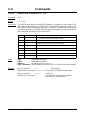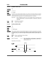
1
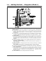
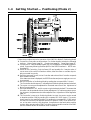
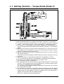
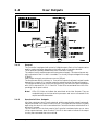
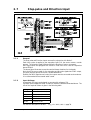
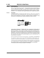
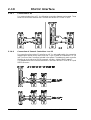
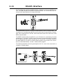
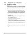
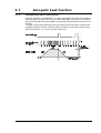
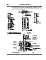
2.2
2.2.1
2.2.2
2.2.3
Motor Output
General Aspects of Motor Connection
The Controller is designed for use with common DC servo motors. The Controller can
supply currents of up to 12 Amp (continuous) and 25 Amp peak.
These current values must be set using the software commands CA and CP.
The Controller Driver uses Mos-Fet transistors, which give especially good performance. The motor voltage is regulated at a frequency of 19.75kHz, which ensures that the
motor does not produce any audible noise as a result of regulation.
The Driver’s switching time is very short (<200nS), which can result in high-frequency
noise components in the cables between the driver and the motor.
In certain situations this can result in undesirable influences on other electronic equipment in proximity to the step motor system. To avoid this problem, the connection between the Controller and the motor should be made using screened cable, as illustrated
above. Further, it is recommended that screened cable is also used for the encoder cable
to avoid influences from the motor cable affecting the encoder signal.
Short-circuiting of the Motor Output
The motor output can withstand short-circuiting between the M+ and M- terminals. In
addition, both motor output terminals will withstand short-circuiting to ground or to the
positive supply.
If a short circuit occurs, the Controller will stop all activity and report an error condition
by activating the Current LED. In addition, the Controller’s error registers will be activated. See the ES and EST commands.
Protection of the Driver
With certain motors, it may be necessary to connect an inductance coil in series with one
of the motor cables. This coil functions as an “elastic” buffer for sudden current transients which would otherwise activate the Controller’s short circuit protection.
JVL Industri Elektronik A/S - User Manual - DC Servo Motor Controller DMC10
16