1
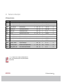
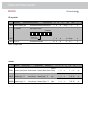
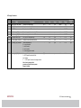
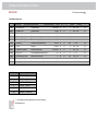
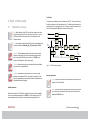
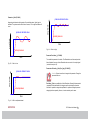
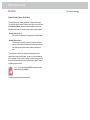
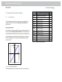
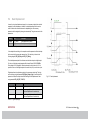
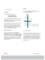
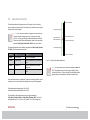
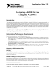
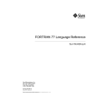
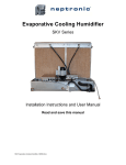
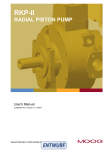
Programmable
Multi-Axis
Servo Drive
System
Speed Controlled Pump
With Pressure Limiting Controller
Software User Manual
1 System description
moog
SCP Software User Manual
SPC Software User Manual 2
.
Technical alterations reserved
The contents of our documentation have been compiled with greatest care and in
compliance with our present status of information.
Id no.: CB90332-001, Rev. 1.0
Date: 07/2014
The English version is the original of this specification
Nevertheless we would like to point that this document cannot always be updated
parallel to the technical further development of our products.
Information and specifications may be changed at any time. For information on the
latest version please refer to [email protected].
Table of Contents
1
2
4
5
System description ................................................... 4
1.1
Introduction ......................................................................................................4
1.2
Overall View of SCP Controller .......................................................................4
Software and Parameter description ........................ 5
2.1
Installation ........................................................................................................5
2.2
Software Overview ...........................................................................................6
2.3
Parameter List Description ...............................................................................7
Basic controller setup ............................................. 13
4.1
Preparation for Setup ......................................................................................13
4.2
Main Parameters .............................................................................................14
Advanced Controller Features ................................ 18
Audience
This document does not replace the MSD Servo Drive Operation Manual. Please be
sure to observe the information contained in the “For your safety”, “Intended use” and
“Responsibility” sections of the Operation Manual (ID no.: CA65642-001). For
information on installation, setup and commissioning, and details of the warranted
technical characteristics of the MSD Servo Drive series, refer to the additional
documentation (Operation Manual, User Manual, etc.).
This document provides information about
The Speed Controlled Pump (SCP) with pressure limiting controller Software. The aim
is to provide an introduction into the features of SCP and corresponding controller
parameters. The installation of the SCP hardware and setup of the drive as well as
setup of the current and classical speed controller is not the subject of this User
manual.
Versions
This document relates to software version 60033 (based on Firmware 123.50-87) from
April 5th, 2013. The software version can be read using the DRIVEADMINISTRATOR,
viewing parameter P 0048.4.
5.1
Linearization ...................................................................................................18
5.2
Dual Displacement ..........................................................................................19
5.3
Parameter Switching Function ........................................................................20
5.4
Protect Features ..............................................................................................21
Title
5.5
Actual Value Path ...........................................................................................22
5.6
Cable Break Detection ....................................................................................23
5.7
Leakage Compensation ...................................................................................24
Moog Servo Drive Application Manual
DRIVEADMINISTRATOR Manual
Moog Servo Drive Operation Manual
AIO Option Card Manual
5.8
Additional Options..........................................................................................24
Referenced Documents
Table of Content
Document No.
(German)
CA65643-002
CA79186-002
CA65642-002
Abbreviations
Abbreviation
RKP
SCP
NVM
PID
moog
Document No.
(English)
CA65643-001
CA79186-001
CA65642-001
CB59508-001
Full Name
Radial Piston Pump
Speed Controlled Pump
Non Volatile Memory (Flash Memory)
proportional-integral-derivative
SPC Software User Manual 3
.
1 System description
moog
SPC Software User Manual 4
.
1 System description
1.2
1.1
The main SCP controller structure is based on cascaded PID control principle. There
are two coupled controllers, one for flow and one for pressure.
An anti-wind-up structure, an observer and advanced protection features are also
implemented.
Introduction
The SCP system includes a Radial Piston Pump, a Servo Motor and a Servo Drive
controlling the motor.
Overall View of SCP Controller
This document does not describe the internal control loops for the motor, like current
control and speed control loop. They are not part of this documentation (see Moog
Servo Drive Operation Manual).
Q_command
Linearisation
Q_feed_forward
Proportional
gain
Pressure_
Command
-
Gain of
Derivative Term
(Pressure Loop)
Integrator with
limitations and
anti-wind-up
P/Q-Selection
Boundaries
Gain of
Derivative Term
(Flow Loop)
actual d Pressure
dt
Observer
(pressure
differentiator)
Velocity
proportional gain
Speed_
Command
[%]
actual
motor
speed [%]
Actual
pressure
Fig. 1.2 Overall View of SCP Controller
Fig. 1.1 Moog Speed Controlled Pump System SCP
The Software is developed to control pressure and flow of the SCP, depending on set
point, working point and parameterization.
Note: The observer represents a differentiator term. It can be used in two
ways, depending on parameters. The first way: the observer works as a
usual D term. It differentiates actual pressure. The second one: it can
also work as a predictor to provide differentiated values without time
delay.
The main controller features are presented in the following table.
Feature Title
Description
Feed forward
A Flow feed forward is implemented.
Linearization
The nonlinearity between speed and flow of the pump can be
compensated.
Dual flow
A pump with dual displacement can be used.
Leakage
compensation
The leakage of the pump can be compensated directly in the
controller.
Cavitation protect
The risk of cavitation can be detected to protect the system.
Integrator antiwind-up
The integral part of the controller has an anti-wind-up
functionality.
Limitations
The controller is able to limit the pump speed and acceleration
in different ways. It is also possible to define different limitations
for different working points (e.g. depending on the sign of
acceleration and velocity).
Parameter set
switching
There are 15 parameter sets available in the controller. The
controller can switch between them in real time, to fulfill the
actual needs of the process.
Actual value input
The input channel for the actual values is selectable.
Possibilities for combining and filtering of the inputs are
implemented.
Cable break
detection
A break of the cables will be detected.
2 Software and Parameter description
2.1
Installation
The SCP software is a fully integrated part of the MSD firmware and comes along with
its own DRIVEADMINISTRATOR View. The new firmware can be installed like any other
MSD firmware. Please note that all parameters (so e.g. the motor parameters) are set
to default values during the installation. If the actual parameter setting should be kept,
it needs to be saved before the firmware upgrade. For a detailed description how to
upgrade the drive firmware please refer to Moog Servo Drive Operation Manual.
It is highly recommended to install a new DRIVEADMINISTRATOR View before working
with the SCP software. After installation the DRIVEADMINISTRATOR will be upgraded
with a new entry in the project tree. All SCP parameters are grouped under this entry.
Fig. 2.1 DRIVEADMINISTRATOR View
Table 1.1 Main Software Features
moog
2 Software and Parameter description
SPC Software User Manual 5
.
2 Software and Parameter description
moog
2.2
SPC Software User Manual 6
Software Overview
All calculations in the SCP controller are in percentage. The output of the SCP
controller is a velocity set point to the motor controller. Therefore the motor controller
for current and speed should be set up before tuning the SCP controller. (see Moog
Servo Drive Operation Manual).
The SCP parameters are grouped in several groups. Every group has several SubIDs. There is no graphical input mask for SCP parameters. The following table
summarizes the parameter groups.
Group ID
Name
Description
P 595
Linearization
Linearization parameters
P 596
Predefined Parameter
Settings
Predefined parameter sets
P 1655
Test Points
General purpose debug variables
P 1996
SCP Floating Point
Variables
SCP Integer Variables
P 1997
SCP Integer Variables
SCP Integer Variables
P 1998
SCP Floating Point
Parameters
SCP Integer Parameters
P 1999
SCP Integer
Parameters
SCP Integer Parameters
(online changeable)
Table 2.1 Parameter Groups
Attention: All parameters are immediately active after changing in the
Moog DRIVEADMINISTRATOR. Change the parameters with care if the
control is active!
The following chapter provides the overview and description of the parameters.
.
2.3
Parameter List Description
SCP Floating Point Variables
Address
Name
Description
Unit
Type
Scope
Default
Range
P 1996.0
Pressure_command
Pressure command input
%
float
yes
3.0
0 - 100
no
P 1996.1
Q_command_input
Q command input
%
float
yes
0
- 100 - 100
no
P 1996.2
Q_feed_forward_input
Q feed forward input
%
float
yes
0
- 100 - 100
no
P 1996.3
Proportional_Gain
Proportional gain; pressure loop
-
float
yes
0
-1000 - 1000
no
P 1996.4
Derivative_Gain
Differentiator gain; flow loop
-
float
yes
0
-10 - 10
no
P 1996.5
Derivative_t
Differentiator time value; flow loop
ms
float
yes
0
0-10000000
no
P 1996.6
Derivative_I_Gain_Pos
Differentiator positive gain; pressure loop
-
float
yes
0,01
-max - max
no
P 1996.7
Derivative_I_Gain_Neg
Differentiator negative gain; pressure loop
-
float
yes
0,01
-max - max
no
P 1996.8
Derivative_I_t
Differentiator time value; pressure loop
ms
float
yes
2
0-10000000
no
P 1996.9
I_Gain
Integrator gain
1/s
float
yes
10
-108 - 108
no
P 1996.10
P_Integrator_Feedback
Integrator feedback gain
-
float
yes
0
-105 – 105
no
P 1996.11
Q_Command_Min_Static
Minimum flow; flow and pressure control
%
float
yes
-100
-100 - 100
no
Gain of observer input at differentiators
-
float
yes
0
-10 – 10
no
P 1996.12
Derivative_Observer_Gain
Table 2.2 Parameter Groups
Stored in Flash
Attention: Changes in the SCP Floating Point Variables wouldn’t be
saved. To save the parameters please use the predefined parameter
sets (see below).
moog
2 Software and Parameter description
SPC Software User Manual 7
.
2 Software and Parameter description
moog
SPC Software User Manual 8
.
Test Points
Address
Name
Description
Unit
Type
Scope
P 1655.0
tst00_Pressure_Command
Test point 00
%
float
yes
Default
P 1655.1
tst01_Q_Command
Test point 01
%
float
yes
n/a
full range
no
P 1655.2
tst02_Q_Command_Compens.
Test point 02
%
float
yes
n/a
full range
no
P 1655.3
tst03_Pressure_Actual
Test point 03
%
float
yes
n/a
full range
no
n/a
Range
full range
Stored in Flash
no
P 1655.4
tst04_Integrator_Input
Test point 04
%
float
yes
n/a
full range
no
P 1655.5
tst05_Integrator_Output
Test point 05
%
float
yes
n/a
full range
no
P 1655.6
tst06_Pressure_Compens._Out
Test point 06
%
float
yes
n/a
full range
no
P 1655.7
tst07_pQ_Selection_Output
Test point 07
%
float
yes
n/a
full range
no
P 1655.8
tst08_Speed_Command
Test point 08
%
float
yes
n/a
full range
no
P 1655.9
tst09_Actual_Speed
Test point 09
%
float
yes
n/a
full range
no
P 1655.10
tst10_Dual_Displace_p-factor
Test point 10
%
float
yes
n/a
full range
no
P 1655.11
tst11_Dual_Displace_Q-factor
Test point 11
%
float
yes
n/a
full range
no
P 1655.12
tst12_ACC_Rate_limit_Active
Test point 12
%
float
yes
n/a
full range
no
P 1655.13
tst13_ACC_Limitation_Input
Test point 13
%
float
yes
n/a
full range
no
P 1655.14
tst14_Differerentiator_Ouput
Test point 14
%
float
yes
n/a
full range
no
P 1655.15
tst15_Differentiator_I_Output
Table 2.3 Test Point
Test point 15
%
float
yes
n/a
full range
no
SCP Floating Point Parameters
Address
Name
Description
Unit
Type Scope Default
Range
Stored in Flash
P 1998.0
DD_Q_factor
Dual displacement Q factor
-
float
yes
1
1 … 100
yes
P 1998.1
DD_p_factor
Dual displacement p factor
-
float
yes
1
1 … 100
yes
P 1998.2
Actual_Value_Path_Factor [0-1]
Weighting two input paths
-
float
yes
0
0…1
yes
Cable_Break_Threshold_ISA0
Cable break detection threshold. The percentage value is
based on 10 V / 20 mA.
For details how to set up the 4 .. 20 mA input please refer to
Moog Servo Drive Operation Manual.
%
float
yes
0
0 … 10
yes
P 1998.3
Cable_Break_Threshold_ISA1
Cable break detection threshold. The percentage value is
based on 10 V / 20 mA.
For details how to set up the 4 .. 20 mA input please refer to
Moog Servo Drive Operation Manual.
%
float
yes
0
0 … 10
yes
P 1998.5
I_MAX_Offset
Integrator positive limit offset
%
float
yes
1
0 … 100
yes
P 1998.6
I_MAX_min
Integrator limitation
%
float
yes
0 -1000 … 1000
yes
P 1998.7
I_MAX_max
Integrator limitation
%
float
yes
100 -1000 … 1000
yes
P 1998.8
I_MIN_min
Integrator limitation
%
float
yes
-100 -1000 … 1000
yes
P 1998.9
I_MIN_max
Integrator limitation
0 -1000 … 1000
yes
P 1998.4
P 1998.10 Speed_Rise_Rate_1
Maximum change of motor speed command
P 1998.11 Speed_Rise_Rate_2
Maximum change of motor speed command
P 1998.12 Velocity_Gain
Motor velocity gain scaling
P 1998.13 Pressure_Cavitation_Limit
Pressure cavitation limit
Leakage_Compensation
P 1998.14
Q cmd mod = Q cmd + pressure * leakage comp'
P 1998.15 Cavitation_Minimum_Velocity
Table 2.4 SCP Floating Point Parameters
Minimum velocity @ cavitation
moog
2 Software and Parameter description
%
float
yes
%/s
float
yes
5000
1 … 106
yes
6
%/s
float
yes
5000
1 … 10
yes
RPM per [%]
float
yes
0
-100 … 100
yes
%
float
yes
3
0 … 100
yes
%speed /
%pressure
float
yes
0
0 … 1000
yes
%
float
yes
0
-100 … 100
yes
SPC Software User Manual 9
.
2 Software and Parameter description
moog
SPC Software User Manual 10
.
SCP Integer Variables
Address
P 1997.0
Name
Description
Unit
Predefined_Parameter_Switch
Switching between predefined parameter data sets
SCP_StatusWord
Status of pressure controller
Type
Scope
int
yes
Set 0 [0]
[]
Default
Range
Stored in Flash
0 … 14
no
i_SVPStatusWord
15 14 13 12 11 10 9
8
7
6
5
4
3
2
0 = flow limitation effective
1 = pressure controller effective
P 1997.1
P 1997.3 DD_ON_OFF
Table 2.5 SCP Integer Variables
Dual displacement factors active
1
0
[]
int
yes
n/a
full range
no
list
int
yes
off
[0, 1]
no
Linearization
Address
P 595.0
P 595.1-10
Name
Description
Linearisation_Number_Elements Number of elements
Linearisation_Input_1 - 10
P 595.11-20 Linearisation_Output_1 - 10
Table 2.6 Linearization
Name
Description
Number of
Linearisation_Number_Elements Elements
Look up table Input
Linearisation_Input_1 - 10
Look up table
Input
Look up table output
Linearisation_Output_1 - 10
Look up table
Output
Unit Type Scope Default
Range
Stored in Flash
[]
int
no
0
0 .. 10
yes
%
int
no
0 -100.. 100
yes
%
int
no
0 -100.. 100
yes
SCP Integer Parameters
Address
Name
Description
Unit
Type
Scope
Default
Range
Stored in
Flash
[0, 1]
int
yes
path 0
[0, 1]
yes
P 1999.0 Actual_Value_Path_Switch
Channel of the actual value
P 1999.1 DD_ON_Delay
Delay time to switch the DD factors active
ms
int
yes
0
0…10000
yes
P 1999.2 DD_OFF_Delay
Delay time to switch DD the factors to 1
ms
int
yes
0
0…10000
yes
P 1999.3 DD_Switching_ON_Time
Time to change the factor from 1 to DD
ms
int
yes
0
0…10000
yes
P 1999.4 DD_Switching_OFF_Time
Time to change the factor from DD to 1
ms
int
yes
0
0…10000
yes
P 1999.5 DD_Digital_output_Logic
DD_ON_OFF relay output logic
list
int
yes
1
0…2
yes
P 1999.6 X4_Cable_Break_Detection
Activation of the cable break detection
-
int
yes
0
0…3
yes
P 1999.7 X4_Analog_Input_Inversion
(Value substitution list)
0 = no input inverted
1 = iea 0 inverted
2 = iea 1 inverted
3 = both analog inputs inverted
-
int
yes
0
0…3
yes
[0,1]
int
yes
0
0…1
yes
P 1999.8 Switching_On_SCP_Controller 0 = normal Position Controller
1 = SCP Speed Controller with fieldbus-Interface
3
= SCP Speed Controller with analog interface
Note: A value change of this
parameter will be active when power
Stage is disabled.
Table 2.7 SCP Integer Parameters
moog
2 Software and Parameter description
SPC Software User Manual 11
.
2 Software and Parameter description
moog
SPC Software User Manual 12
.
Predefined parameter sets
Address
Name
Description
Unit
Type
Scope
Default
Range
Stored in Flash
P 596.0
00_Proportional_Gain
Proportional gain
factor/10000
int
no
0
-max … max
yes
P 596.1
00_Derivative_Gain
Differentiator gain
s/10000
int
no
0
-max … max
yes
P 596.2
00_Derivative_t
Differentiator time
ms/1000
int
no
0
0 … max
yes
P 596.3
00_Derivative_I_Gain_Pos
Differentiator positive gain; pressure loop
s/10000
int
no
10
-max … max
yes
P 596.4
00_Derivative_I_Gain_Neg
Differentiator negative gain; pressure loop
s/10000
int
no
10
-max … max
yes
P 596.5
00_Derivative_I_t
Differentiator time; pressure loop
ms/1000
int
no
2000
0 … max
yes
P 596.6
00_I_Gain
Integrator
1/s/10000
int
no
10
-max … max
yes
P 596.7
00_P_Integrator_Feedback
Integrator feedback gain
factor/10000
int
no
0
-max … max
yes
P 596.8
00_DD_ON_OFF
ON: dual displacement factors active
List
int
no
off
[0, 1]
yes
P 596.9
00_Q_Command_Min_Static
Minimum flow; p and Q ctrl.
%
int
no
-100
-100 … 100
yes
P 596.10
00_Actual_value_Path_Switch
[0, 1]
int
no
path 0
[0, 1]
yes
1/10000
int
no
0
P 596.11 00_Derivativ_Observer_Gain
Table 2.8 Predefined parameter sets
Parameter Set No.
Parameter No.
0
P 0596.0 … P0596.15
1
P 0596.16 … P0596.31
2
P 0596.32 … P0596.47
3
P 0596.48 … P0596.63
...
Channel of the actual value
Gain of observer input at differentiators
...
14
P 0596.224 … P 0596.239
Table 2.9 Parameter set numbers
Note: Value range of predefined parameter sets will not be checked by
DRIVEADMINISTRATOR.
-100000 – 100000
yes
Test Points
4 Basic controller setup
4.1
Preparation for Setup
Note: Before starting with the SCP controller, the hardware, the current
control and the speed control of the motor has to be set up. To run the
MSD without SCP controller please refer to the Moog Servo Drive
Operation Manual.
Note: It is possible to switch between SCP controller and standard speed
controller by parameter Switching_On_SCP_controller (P 1999.8).
Tests points were created to monitor the behavior of the SCP. They can be shown on
the digital oscilloscope in the DRIVEADMINISTATOR. The following picture presents the
main test points in the overall controller view. The green numbers corresponds to the
Sub-ID of the parameter P 1655 and to the name of the test point.
Q_command
Attention: Before activating the pump, all relevant limitations and safety
functions have to be parameterized.
Attention: Parameterize and start the new SCP with care! A wrong
parameter can damage the SCP or the machine. Pay attention to the
sign of the parameters to prevent positive feedback. All parameters are
immediately active after changing.
02
Q_feed_forward
Proportional
gain
Pressure_
Command
00
Attention: The dual displacement part of the software uses the brake
output as a digital output. For the use of the brake output parameter
motor brake output X13/X20 needs to be set to 41 (P 0125 in drive
settings / I/O-Configuration / Motor brake output).
Linearisation
01
04
-
-
Integrator with
limitations and
anti-wind-up
Gain of
Derivative Term
(Pressure Loop)
06
05
P/Q-Selection
07
Boundaries
Gain of
Derivative Term
(Flow Loop)
15
14
actual d Pressure
dt
Observer
(pressure
differentiator)
Velocity
proportional gain
Speed_
Command
[%]
08
actual
motor
speed [%]
09
Actual
pressure
03
Fig. 4.1 SCP Controller test points
Start-up preparations
Note: To adjust the input channel of the actual value, please refer to the
chapter 5.5 Actual Value Path.
Default parameters
Before the first start of the SCP software (transition to the state “operation enabled”)
check over the predefined parameter set (P 596.0-.11). After switching on the SCP
actual parameters will be copied from the first parameter set (parameter set 0).
moog
4 Basic controller setup
Note: To prove the controller calculation without active motor movement
(e.g. to check the communication with sensors and controller) set the
parameter P 1998.12 to zero.
SPC Software User Manual 13
.
4 Basic controller setup
moog
SPC Software User Manual 14
Before starting up the SCP necessary limits have to be set. The following table
summarizes all limits in the SCP controller. The descriptions of these limits can be
found in respective chapters.
Address
Name
Description
4.2
.
Main Parameters
In most cases it is enough to setup only the main parameters to achieve a good
control performance. From the control point of view the main parameters are:
P 1996.11
Q_Command_Min_Static
Minimum Flow; p and Q control
P 1998.3
Cable_Break_Threshold_ISA0
Cable break detection threshold
Parameter
Number
P 1998.4
Cable_Break_Threshold_ISA1
Cable break detection threshold
P 1998.12
Velocity_Gain
Velocity proportional gain
P 1998.6
I_MAX_min
Integrator limitation
P 1996.9
I_Gain
Integrator gain
P 1998.7
I_MAX_max
Integrator limitation
P 1998.8
I_MIN_min
Integrator limitation
P 1996.8
Derivativ_I_t
Time value of differentiator in
observer
P 1998.9
I_MIN_max
Integrator limitation
P 1998.10
Speed_Rise_Rate_1
Maximum change of
motor speed command
P 1996.6 (7)
Derivativ_I_Gain_Pos
(_Neg)
Gain of derivative term in
pressure control for positive and
negative signal direction
P 1998.11
Speed_Rise_Rate_2
Maximum change of
motor speed command
P 1998.13
Pressure_Cavitation_Limit
Pressure cavitation limit
P 1998.15
Cavitation_Minimum_Velocity
Table 4.1 Limits in the SCP controller
Name
P 1996.12
Derivativ_Observer_Gain
Table 4.2 Main parameters
Description
Observer gain
The following chapters describe the effect of the parameters.
Minimum velocity @ cavitation
Motor setup for speed control loop has to be done according to the Moog Servo Drive
Operation Manual. The Motor must be able to run in a speed control loop. If this is not
given, disconnect the pump from the motor and start the motor commissioning without
connection to the pump.
After reattaching the pump to the motor adjust the pressure relief valve in the hydraulic
system to the lowest possible setting to avoid system damage.
After setting the limits the main SCP parameters can be adjusted.
Note: To monitor the system behavior, please make use of test
points (P 1655).
Parameter: Velocity_Gain (P 1998.12)
Velocity proportional gain calculates the percentage of revolution per minute [RPM/%].
There are pumps available for clock wise or counter clockwise rotation. At this point a
right sign is important. The positive signal of the speed command (test point 08)
corresponds to the flow which leads to pressure increase in the hydraulic system. If
not, change the sign of the parameter velocity gain P 1998.12.
Parameter: I_Gain (P 1996.9)
pressure demand value
pressure demand value
amplitude
Integrator gain determines the dynamics of the controlled system. Higher I gain is
desirable. The system reaction will be faster. However, if it's too high oscillations will
occur.
amplitude
actual pressure
time
actual pressure
Fig. 4.4 I-Gain is to high
Parameter: Derivative_I_t (P 1996.8)
time
The smaller this parameter is the better. The differentiation runs faster and provides
faster feedback. However, a faster differentiator has more noise in the output signal
(monitor the test point 15).
Fig. 4.2 I-Gain is to low
Parameters: Derivative_I_Gain_Pos(_Neg) (P 1996.6(7))
pressure demand value
amplitude
Attention: System is sensitive to changes in this parameter. Change the
parameter with care.
actual pressure
Derivative_I_Gain is an amplification of the differentiator. Generally this parameter is
responsible for the stabilization of the integrator and for minimizing the overshoot.
Note that it’s possible to change the amplification for positive and negative pressure
changing direction separately. However, in most cases they are the same.
time
Fig. 4.3 I-Gain is well parameterized
moog
4 Basic controller setup
SPC Software User Manual 15
.
4 Basic controller setup
moog
Parameter: Derivative_Observer_Gain (P 1996.12)
The differentiator receives a delayed signal because of piping and sensor delays.
Thus, the stability margin is reduced. An observer can be used to overcome this issue.
On the Derivative_Observer_Gain the motor speed is additionally included in the
differentiation of the pressure to eliminate the delays caused by hydraulic capacities.
• Derivative_Observer_Gain = 0
Observer works as a differentiator. The actual pressure will be differentiated.
• Derivative_Observer_Gain > 0
The observer function (prediction) is turned on. The pressure derivative is
additionally formed even with the actual speed. Dead time is eliminated, and
the integrator gain can be further increased. System can be made even
faster.
To set the Derivative_Observer_Gain the phase of the actual speed should be
compared with the output of the differentiator. It is easy to do, since both signals are
given in percentage. The aim is that the two signals are in phase with each other. The
margin of stability is dominated by the phase lag between the two signals. Therefore
the phase lag must be minimized.
Attention: Correct sign of parameter P1996.12 is important for stability
(compare with the sign of P1998.12)
The following examples illustrate the parameterization.
SPC Software User Manual 16
.
Fig. 4.5 Example behavior without observer (Derivative_Observer_Gain =0)
Fig. 4.6 I- Example behavior with well parameterized observer
A phase lag between the two signals is visible.
The two signals are in phase.
moog
4 Basic controller setup
SPC Software User Manual 17
.
5 Advanced Controller Features
moog
SPC Software User Manual 18
Parameter
Number
Name
P 595.0
Linearisation_Number_Elements
P 595.1
Linearisation_Input_1
-100
P 595.2
Linearisation_Input_2
-60
P 595.3
Linearisation_Input_3
-20
P 595.4
Linearisation_Input_4
20
P 595.5
Linearisation_Input_5
60
P 595.6
Linearisation_Input_6
100
Up to 10 values for each axis can be defined. The number of used values needs to be
defined in parameter Linearisation_Number_Elements. Set this parameter to zero to
switch the linearization off. Between the values, the output value is interpolated linear.
P 595.11
Linearisation_Output_1
-100
P 595.12
Linearisation_Output_2
-80
P 595.13
Linearisation_Output_3
-40
In the following figure shows an example with 6 interpolation points. In this example
signals in a middle range (20 – 80 % amplitude) are weighted higher than signals
around 0 and 100 %.
P 595.14
Linearisation_Output_4
-40
P 595.15
Linearisation_Output_5
5 Advanced Controller Features
5.1
Linearization
The nonlinearity between speed and flow of the pump can be compensated. The
linearization will be active if the parameter Linearisation_Number_Elements is
greater than zero.
Output
Setting up the parameters
100%
Input
100%
-100 %
-100 %
Fig. 5.1 Look –up table for linearization
The linearization parameters for the example above need to be set up as following:
P 595.16
Linearisation_Output_6
Table 5.1 Example linearization parameters
Value
6
80
100
.
5.2
Dual Displacement
In case of using a dual displacement pump it is not necessary to adjust the controller
separately for each displacement. Instead, the dual displacement function can be
used. It switches the controller between two adjustable gains. All necessary
parameters will be weighted by these gains automatically. The gains are saved in the
parameters:
Address
Name
Description
P 1998.0
DD_Q_factor
Dual displacement Q factor
P 1998.1 DD_p_factor
Dual displacement p factor
Table 5.2 Dual displacement factors
A time delay before switching to the respective controller parameter reflects the delay
that is caused by the pumps step response time. The time delay is shown in the
following diagram (DD_ON_Delay and DD_OFF_Delay).
The dual displacement part of the software uses the brake output as a digital output.
For the use of the brake output parameter Motor brake Output X13/X20 (P 0125 in
Drive settings / I/O-Configuration / Motor brake output) needs to be set to 41. It is
possible to set one of the digital outputs to the same value (41) to monitor the output.
Digital output has to be adjusted according to the necessary output logic. The logic
can be chosen using the parameter DD_Digital_Output_Logic. A new Value in this
parameter will affect the output value after switching the dual displacement Value
using parameter DD_ON_OFF (P 1997.3).
Parameter
DD_ON_OFF
Value
Fig. 5.2 Dual displacement
Function
0
Digital output disabled
1 (ANALOG IN 0)
Normal logic (digital output is switched on
when dual displacement is switched on)
2
Negative logic (digital output is switched off
when dual displacement is switched on)
Table 5.3 Digital output logic
moog
5 Advanced Controller Features
SPC Software User Manual 19
.
5 Advanced Controller Features
moog
5.3
SPC Software User Manual 20
Attention: During switching on the SCP controller the actual parameters
will be copied from the parameter set No. 0 (P 0596.0 – P 0596.15).
Changes in the SCP Floating Point Variables wouldn’t be saved.
Parameter Switching Function
The SCP firmware can handle 15 different predefined parameter sets. These
parameter sets are saved in the drive parameter P 0596, Sub-ID 0 - 239. Using
parameter Predefined_Parameter_Switch a switching process will be started.
11 different parameters are defined:
Parameter
Number
Name
Multiplier
0
Proportional_Gain
factor 10000 (*)
1
Derivative_Gain
factor 10000 (*)
2
Derivative_t
factor 1000 (*)
3
Derivative_I_Gain_Pos
factor 10000 (*)
4
Derivative_I_Gain_Neg
factor 10000 (*)
5
Derivative_I_t
factor 1000 (*)
6
I_Gain
factor 10000 (*)
7
P_Integrator_Feedback
factor 10000 (*)
8
DD_ON_OFF
boolean (**)
9
Q_Command_Min_Static
factor 1
10
Actual_Value_Path
boolean (**)
11
Derivative_Observer_Gain
Table 5.4 Predefined parameters
factor 10000 (*)
(*)These parameters are divided by the value in the column “Multiplier” during the
copying process.
(**) Binary parameter. Possible Values: 0 = off, 1 = on.
Example: To maintain a Proportional_Gain value of 1.234 you need to store 12340
as the predefined value. This value is divided by the factor of 10000 during the
switching process and 1.234 is maintained in the Proportional_Gain parameter.
.
Switching between different parameter sets
The active parameter set is chosen according to the parameter
Predefined_Parameter_Switch (P 1997.0) and the state of the digital inputs ISD03 –
ISD06. If the bit coded sum is above 14 then parameter set 14 will be selected. The
switching mechanism is independent of the drive state (power stage enabled /
disabled)
ISD06
ISD05
ISD04
ISD03
Chosen Parameter Set, in case
Predefined_Parameter_Switch is zero.
Low
Low
Low
Low
0
Low
Low
Low
High
1
Low
Low
High
Low
2
Low
Low
High
High
3
Low
High
Low
Low
4
Low
High
Low
High
5
Low
High
High
Low
6
Low
High
High
High
7
High
Low
Low
Low
8
High
Low
Low
High
9
High
Low
High
Low
10
High
Low
High
High
11
High
High
Low
Low
12
High
High
Low
High
13
High
High
High
Low
Table 5.5 Choosing of parameter set
14
5.4
Protect Features
Cavitation protection
The related parameters to the cavitation protection are
•
Pressure_Cavitation_Limit (P 1998.13)
•
Cavitation_Minimum_Velocity (P 1998.15)
There is a risk of cavitation if the pressure in the system goes under a certain level –
Pressure_Cavitation_Limit (P 1998.13). In such a situation cavitation protect will be
active and the predefined minimum speed will be set.
The following example describes the functionality of cavitation protection: there is a
cavitation risk and the pump speed needs to be decrease fast. The integrator in the
pressure loop is on the lower limit and needs time to come up. In this situation
cavitation_limit will be active and overwrites the integrator output with the cavitation
minimum velocity Cavitation_Minimum_Velocity (P 1998.13).
Integrator limits and anti-wind-up
Anti-wind-up can limit the integrator for stability reasons. I_MIN_max(min),
I_MAX_max(min) are the boundaries in which the limit can be set by the anti-wind-up.
The lower limitation is allowed in the boundaries between I_MIN_max and I_MIN_min
(e.g. from 0 % to -100 %, default values). The upper limitation is between I_MAX_max
and I_MAX_min (e.g. from 100 % to 0 %, default values). Additional positive limit can
be increased by using parameter I_MAX_Offset. However, it is recommended to keep
this parameters default value.
moog
5 Advanced Controller Features
Rate limitation
The parameters Speed_Rise_Rate_1 (2) (P 1998.10(11)) defines the limit of the
motor acceleration, also called Rate Limitation.
Acceleration a
II.
I.
Speed n
III.
IV.
Speed_Rise_Rate_2 active
Speed_Rise_Rate_1 active
Fig. 5.3 Rate limitation quadrants
In the quadrants II, III and IV the physical limit of the acceleration is given only due to
the mechanical characteristic of the pump. These quadrants are less critical. On the
other hand there is a risk of cavitation in the supply pipeline in the quadrant I. Because
of this, two Speed_Rise_Rates are given. The rate limitation provides the limited
speed command output. Moreover, it provides a signal to anti-wind-up function of the
integrator, so called ACC. By using the test points 12 and 13 (P 1655.12-13) ACC
limitation can be monitored.
SPC Software User Manual 21
.
5 Advanced Controller Features
moog
5.5
SPC Software User Manual 22
Act.
pressure
input 1
Actual Value Path
Scaling
+
Offset
Low
Pass
Filter
Scaling
+
Offset
Low
Pass
Filter
P1999.0
inverter
r_pressure_
actual[%]
Depending on the state of P1999.8 different analog inputs are used.
P1999.8 value
Input names
Ports
1
(SCP with Field
bus Interface)
Actual pressure, input 1
MSD.AIN 0 (X4)
Actual pressure, input 2
MSD.AIN 1 (X4)
Other signals
field bus
Pressure command
MSD.AIN 0 (X4)
Flow command
MSD.AIN 1 (X4)
Actual pressure, input 1
MSD.AIN 2 (Option 2)
Actual pressure, input 2
MSD.AIN 3 (Option 2)
Pressure feedback
MSD.AOUT 2 (Option 2)
2
(SCP with Analog
I/O Interface)
Motor speed
Table 5.6 Actual value path
Act.
pressure
input 2
P1998.2
(*)
(**)
.
inverter
+
+
P1999.7
Fig. 5.4 Structure of actual value path
(*) Gain and offset of analog inputs can be set in parameters P 0428 and P 0429. A
gain of 1 in P0428 will result in a pressure value of 100 % if 10 V are applied at analog
input 1. New values are accepted after disabling / enabling the drive.
MSD.AOUT 3 (Option 2)
Cable break detection is available for analog inputs. For Voltage inputs (±10 V) this
cable-break-detection is described in chapter Cable Break Detection. For current
inputs (0-20 mA / 4-20 mA) a standard MSD Servo Drive function will be used, please
refer the AIO Option Card Manual.
In case actual values are connected to X4, actual value path has the following
structure.
(**) Low pass filter time can be set in MSD parameters P 0405 and P 0406 (using the
Moog DRIVEADMINISTRATOR). New values are accepted after disabling / enabling the
drive.
In case actual values are connected to optional I/O card, identical structure will be
used. However, the parameters to adjust gain, offset and filter are different. In this
case please refer to AIO Option Card Manual.
5.6
Cable Break Detection
maximum scaled value
The cable break detection will generate an error if the signal of one of the analog
inputs is outside of an allowed range. This detection is only active if the power stage of
the Moog Servo Drive is enabled.
Note: The SCP cable break detection is designed for Inputs at the front
connector X4 and for voltage inputs only. For analog current inputs
(0-20 mA / 4-20 mA) use the build-in cable break detection mechanism.
Please refer the AIO Option Card Manual for details. In this case set the
parameter Cable_Break_Detection (P 1999.6) to zero (no detection).
The cable break detection can be activated using parameter Cable_Break_Detection
(P 1999.6). The following values are possible:
Parameter
Value
Function
P 1999.6
0 (no detection)
Function is not activated
P 1999.6
1 (ANALOG IN 0)
Function is activated only for first analog
input
P 1999.6
2 (Analog In 1)
Function is activated only for second
analog input
P 1999.6
1 (Analog In 0)
Function is activated for both analog
inputs
Table 5.7 Cable break detection
normal operating range
in this range a cable
break will be detected
cable break threshold value
0
- cable break threshold value
normal operating range
- maximum scaled value
Fig. 5.5 Scaling of the cable break detection
Note: The Failure reaction can be selected in parameter P 0030 SubID 52. This parameter value must not be ignored. Setting 4 (Servo
Halt with Quick-Stop) or 5 (Servo Halt with Quick-Stop and protection
against restart) is recommended for the Speed Controlled Pump.
If the cable break detection is enabled and the value of the analog input (after internal
scaling) is in the area of the cable break threshold value an error will be generated:
Cable break detected at analog input 1: Error 52-03.
Cable break detected at analog input 2: Error 52-04.
The threshold for a failure reaction can be set up using the parameters
Cable_Break_Threshold_ISA0 and Cable_Break_Threshold_ISA1. The scale of
these parameters is [%] - so a value of 10 % means 1 V for 0-10 V Voltage input.
moog
5 Advanced Controller Features
SPC Software User Manual 23
.
5 Advanced Controller Features
moog
5.7
Leakage Compensation
The parameter Leakage_Compensation (P 1998.14) has a dimension
[speed / pressure]. The compensated Flow command will be calculated according to
q_cmd_mod= q_cmd+Leakage_Compensation*Pressure.
It means, even if external flow command is set to zero, some flow will be generated
(Assuming pressure is not equal to zero). With the right parameterization this flow is
equal to leakage.
SPC Software User Manual 24
5.8
.
Additional Options
Depending on the requirements, additional parameters as described below may be
used to improve the system behavior. However, in most cases these parameters can
be set to default values.
Address
Name
Description
P 1996.3
Proportional_Gain
Proportional gain
P 1996.4
Derivative_Gain
Differentiator gain; flow loop
P 1996.5
Derivative_t
Differentiator time value; flow loop
P 1996.10
P_Integrator_Feedback
Integrator feedback gain
P 1996.11 Q_Command_Min_Static
Table 5.8 Additional options
Minimal flow; p and Q control
Proportional_Gain: This parameter describes the proportional gain in case of PI
Pressure control (see Fig. 1.2).
Derivative_Gain and Derivative_t are the parameters of the d-term in the flow control
loop. These parameters can improve the behavior of the flow controller.
Integrator behavior can be improved by internally using the additional feedback. The
feedback gain can be adjusted by using the parameter P_Integrator_Feedback.
Q_Command_Min_Static set the minimal limit of the pump flow. Be careful with the
sign of this parameter.
TAKE A CLOSER LOOK.
Moog solutions are only a click away. Visit our worldwide Web site for more
information and the Moog facility nearest you.
MOOG
Moog GmbH
Hanns-Klemm-Straße 28
D-71034 Böblingen
Telefon +49 7031 622 0
Telefax +49 7031 622 100
www.moog.com/industrial
[email protected]
Moog is a registered trademark of Moog, Inc. and its subsidiaries.
All quoted trademarks are property of Moog, Inc. and its subsidiaries.
All rights reserved.
© 2015 Moog GmbH
Technical alterations reserved.
The contents of our documentation have been compiled with greatest care and in
compliance with our present status of information.
Nevertheless we would like to point that this document cannot always be updated
parallel to the technical further development of our products.
Information and specifications may be changed at any time. For information on
the latest version please refer to [email protected].
Id no.: CB90332-001, Rev. 1.0
Date: 04/2015
Applicable as from firmware version:
The English version is the original of this specification