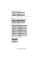
1
i
Preface
Copyright
This publication, including all photographs, illustrations and software, is protected
under international copyright laws, with all rights reserved. Neither this manual, nor
any of the material contained herein, may be reproduced without written consent of
the author.
Version 3.0A
Disclaimer
The information in this document is subject to change without notice. The manufacturer makes no representations or warranties with respect to the contents hereof and
specifically disclaims any implied warranties of merchantability or fitness for any
particular purpose. The manufacturer reserves the right to revise this publication and
to make changes from time to time in the content hereof without obligation of the
manufacturer to notify any person of such revision or changes.
Trademark Recognition
Microsoft, MS-DOS and Windows are registered trademarks of Microsoft Corp.
MMX, Pentium, Pentium-II, Pentium-III, Celeron are registered trademarks of Intel
Corporation.
Other product names used in this manual are the properties of their respective
owners and are acknowledged.
Federal Communications Commission (FCC)
This equipment has been tested and found to comply with the limits for a Class B
digital device, pursuant to Part 15 of the FCC Rules. These limits are designed to
provide reasonable protection against harmful interference in a residential installation. This equipment generates, uses, and can radiate radio frequency energy and, if
not installed and used in accordance with the instructions, may cause harmful interference to radio communications. However, there is no guarantee that interference
will not occur in a particular installation. If this equipment does cause harmful
interference to radio or television reception, which can be determined by turning the
equipment off and on, the user is encouraged to try to correct the interference by one
or more of the following measures:
•
•
•
•
Reorient or relocate the receiving antenna
Increase the separation between the equipment and the receiver
Connect the equipment onto an outlet on a circuit different from that to
which the receiver is connected
Consult the dealer or an experienced radio/TV technician for help
Shielded interconnect cables and a shielded AC power cable must be employed with
this equipment to ensure compliance with the pertinent RF emission limits governing this device. Changes or modifications not expressly approved by the system’s
manufacturer could void the user’s authority to operate the equipment.
Preface
ii
Declaration of Conformity
This device complies with part 15 of the FCC rules. Operation is subject to the
following conditions:
•
•
This device may not cause harmful interference, and
This device must accept any interference received, including interference that may cause undesired operation
Canadian Department of Communications
This class B digital apparatus meets all requirements of the Canadian Interferencecausing Equipment Regulations.
Cet appareil numérique de la classe B respecte toutes les exigences du Réglement sur
le matériel brouilieur du Canada.
About the Manual
The manual consists of the following:
Describes features of the
motherboard.
page 1
Go to H
Chapter 1
Introducing the Motherboard
Describes installation of
motherboard components.
Chapter 2
Installing the Motherboard
Go to
H
page 7
Provides information on using the
BIOS Setup Utility.
Chapter 3
Using BIOS
Go to
Chapter 4
Using the Motherboard Software
H
page 29
Describes the motherboard
software
Go to
Preface
H
page 51
iii
TABLE OF CONTENTS
Preface
i
Chapter 1
1
Introducing the Motherboard
1
Introduction...................................................................................1
Feature..............................................................................................2
Motherboard Components..................................................................5
Chapter 2
7
Installing the Motherboard
7
Safety Precautions...........................................................................7
Choosing a Computer Case............................................................7
Installing the Motherboard in a Case............................................7
Checking Jumper Settings...............................................................8
Setting Jumpers.......................................................................8
Checking Jumper Settings.......................................................9
Jumper Settings.......................................................................9
Installing Hardware....................................................................10
Installing the Processor.........................................................10
Installing Memory Modules..................................................12
Expansion Slots....................................................................14
Connecting Optional Devices................................................16
Installing a Hard Disk Drive/CD-ROM/SATA Hard Drive...21
Installing a Floppy Diskette Drive.........................................22
Connecting I/O Devices................................................................23
Connecting Case Components.....................................................25
Front Panel Header...............................................................27
Chapter 3
29
Using BIOS
29
About the Setup Utility................................................................ 29
The Standard Configuration..................................................29
Entering the Setup Utility........................................................29
Using BIOS......................................................................................30
Standard CMOS Features.....................................................31
Advanced BIOS Features......................................................33
Advanced Chipset Features...................................................36
iv
Integrated Peripherals.................................................................38
Power Management Setup...........................................................42
PNP/PCI Configurations.............................................................44
PC Health Status..........................................................................45
Frequency Control.......................................................................46
Load Fail-Safe Defaults Option...................................................47
Load Optimized Defaults Option.................................................47
Set Password................................................................................48
Save & Exit Setup.........................................................................48
Exit Without Saving.......................................................................48
Updating the BIOS............................................................49
Chapter 4
51
Using the Motherboard Software
51
About the Software CD-ROM............................................................51
Auto-installing under Windows 2000/XP...................................51
Running Setup........................................................................52
Manual Installation........................................................................54
Utility Software Reference............................................................54
1
Chapter 1
Introducing the Motherboard
Introduction
Thank you for choosing the 945GCT-M3 motherboard. This motherboard is a high
performance, enhanced function motherboard designed to support the LGA775 socket
Intel® CoreTM 2 Duo/Pentium ® D/Pentium® 4/Celeron ® D processors for high-end
business or personal desktop markets.
The motherboard incorporates the 945GC Northbridge (NB) and ICH7 Southbridge
(SB) chipsets. The Northbridge supports a Front Side Bus (FSB) frequency of 1066/
800/533 MHz using a scalable FSB Vcc_CPU. The memory controller supports
DDR2 memory DIMM frequencies of 667/533/400. It supports two DDR2 sockets
with up to maximum memory of 2 GB. DDR2 memory bandwidth of 4.3 Gb/s in
single-channel is supported, or 8.5 Gb/s in dual-channel interleaved mode assuming
DDR2 667 MHz. High resolution graphics via one PCI Express slot, intended for
Graphics Interface, is fully compliant to the PCI Express Base Specification revision
1.0a.
The ICH7 Southbridge supports two PCI slots which are PCI v2.3 compliant. In
addition, one PCI Express x1 slot is supported, fully compliant to the PCI Express
Base Specification, Revision 1.0a. It implements an EHCI compliant interface that
provides 480 Mb/s bandwidth for eight USB 2.0 ports. One onboard IDE connector
supports 2 IDE devices in Ultra ATA 100/66/33 mode. The Southbridge integrates a
Serial ATA host controller that is SATA II compliant, supporting four SATA ports
with maximum transfer rate up to 3.0 Gb/s each.
The motherboard is equipped with advanced full set of I/O ports in the rear panel,
including PS/2 mouse and keyboard connectors, COM1, LPT, one VGA port, four
USB ports, one LAN port, one optional 1394a port and audio jacks for microphone,
line-in and 6/8-channel (optional) line out.
Introducing the Motherboard
2
Feature
Processor
The motherboard uses an LGA775 type of Intel ® CoreTM 2 Duo/Pentium® D/
Pentium® 4/Celeron® D that carries the following features:
•
•
•
Accommodates Intel® CoreTM 2 Duo/Pentium® D/Pentium® 4/Celeron® D
processors
Supports a system bus (FSB) of 1066/800/533 MHz
Supports “Hyper-Threading” technology CPU
“Hyper-Threading” technology enables the operating system into thinking it’s
hooked up to two processors, allowing two threads to be run in parallel, both on
separate “logical” processors within the same physical processor.
Chipset
The 945GC Northbridge (NB) and ICH7 Southbridge (SB) chipsets are based on
an innovative and scalable architecture with proven reliability and performance.
945GC (NB)
•
•
•
•
•
ICH7 (SB)
•
•
•
•
•
•
Supports 32-bit host bus addressing, allowing the CPU
to access the entire 2 GB of the memory address
space
2 GB/s point-to-point Direct Media Interface (DMI) to
ICH7 (1 Gb/s) each direction
Supports one PCI Express x16 for Graphics Interface, fully compliant to the PCI Express Base Specification revision 1.0a.
Supports 256-Mb, 512-Mb and 1-Gb DDR2 technologies for x8 and x16 devices
Supports high quality 3D setup, Render Engine and
high-quality texture engine
Enhanced DMA Controller, interrupt controller, and timer
functions
Compliant with PCI Express Base Specification, Revision 1.0a
Compliant with PCI 2.3 specification
Integrated SATA 3.0 Gb/s Host Controller
Integrated USB 2.0 Host Controller supporting up to
eight USB 2.0 ports
Integrated IDE controller supports Ultra ATA 100/66/33
Memory
•
•
•
Supports DDR2 667/533/400 DDR SDRAM with Dual-channel architecture
Accommodates two unbuffered DIMMs
Up to 1 GB per DIMM with maximum memory size up to 2 GB
Introducing the Motherboard
3
1394a FireWire (Optional)
•
•
•
Compliant with single chip host controller for IEEE Std 1394-1995
and IEEE 1394a-2000
Integrated 400 Mbit 2-Port PHY for the PCI BUS
3.3V Power Supply with 5V Tolerant Inputs
Onboard LAN (Optional)
The onboard LAN controller provides the following features:
•
•
•
Integrated 10/100/1000 transceiver
Supports PCI v2.3, 32-bit, 33/66 MHz
Supports fully with IEEE802.3, IEEE802.3u and IEEE802.3ab
•
•
•
Supports 10/100 Mb/s N-Way Auto negotiation operation
Half/Full duplex capacity
Supports wake-On-LAN (WOL) function and remote wake-up
Audio (Optional)
•
•
•
•
•
•
•
•
•
•
•
•
•
•
•
•
•
8-channel of DAC support 24/20/16-bit PCM format for 7.1
audio solution
Support 192K/96K/48K/44.1KHz DAC sample rate
Power support: Digital: 3.3V; Analog: 3.3V~5.25V
Meets Microsoft WHQL/WLP 2.0 audio requirements
Direct Sound 3DTM compatible
Dolby Digital Encorder output for consumer electronic application
Compliant with Intel High Definition Audio, supporting 8-channel
DACs with 95dB S/N ratio
Capabilities: 192/96/48/44.1 KHz with 24/20/16 bits
Power support: Digital: 3.3V; Analog: 3.3V/5.0V
All analog jacks are stereo input and output re-tasking for analog plug & play
Meets Microsoft WHQL/WLP 2.0 audio requirements
Direct Sound 3DTM compatible
Dolby Digital Encoder output for consumer electronic application
Compliant with the AC’97 v2.3 CODEC
Supports 6-channel audio CODEC designed for PC multimedia
systems
Provides three analog line-level stereo inputs with 5-bit volume
control:
Line-in ,CD,AUX
Meets Microsoft WHQL/WLP 2.0 audio requirements
Introducing the Motherboard
4
Expansion Options
The motherboard comes with the following expansion options:
•
•
•
•
•
•
One PCI Express x16 slot for Graphic Interface
One PCI Express x1 slot
Two 32-bit PCI v2.3 compliant slots
One 40-pin IDE low profile header that support two IDE devices
One floppy disk drive interface
Four 7-pin SATA connectors
The motherboard supports UDMA bus mastering with transfer rates of 100/66/33
Mb/s.
Integrated I/O
The motherboard has a full set of I/O ports and connectors:
•
•
•
•
•
•
•
•
Two PS/2 ports for mouse and keyboard
One serial port
One parallel port
One VGA port
Four USB ports
One 1394a port (optional)
One LAN port
Audio jacks for microphone, line-in and 6/8-channel (optional) lineout
BIOS Firmware
This motherboard uses Award BIOS that enables users to configure many system
features including the following:
•
•
•
•
Power management
Wake-up alarms
CPU parameters
CPU and memroy timing
The firmware can also be used to set parameters for different processor clock
speeds.
1. Some hardware specifications and software items are subject to change
without prior notice.
2. Due to chipset limitation, we recommend that motherboard be operated
in the ambiance between 0 and 50 ° C.
Introducing the Motherboard
5
Motherboard Components
Table of Motherboard Components
LABEL
1. CPU Socket
®
2. CPU_FAN
3. DIMM1~2
4. IRDA
5. FDD
6. ATX1
7. IDE1
8. CHS_FAN
9. CLR_CMOS
10. EL**
11. SATA1~4
12. PANEL1
13. JLPC**
14. USB1~2
15. 1394A2*
16. BIOS_WP
17. COM2*
18. WOL1*
19. SPDIFO or S/PDIF**
20. F_AUDIO
21. AUX_IN*
22. PCI1~2
23. PCIE1
24. PCIEX16
25. SYS_FAN
26. ATX12V
*
COMPONENTS
®
LGA775 socket for Intel CoreTM 2 Duo/Pentium® D
®
/Pentium 4/Celeron D CPUs
CPU cooling fan connector
240-pin DDR2 SDRAM slots
Infrared header
Floppy disk drive connector
Standard 24-pin ATX power connector
Primary IDE connector
System cooling fan connector
Clear CMOS jumper
LED header
Serial ATA connectors
Front panel switch/LED header
Low pin count header
Front Panel USB headers
IEEE 1394a header
BIOS flash protect jumper
Onboard Serial port header
Wake On LAN connector
SPDIF out header
Front panel audio header
Auxiliary In connector
32-bit add-on card slots
PCI Express x1 slot
PCI Express slot for graphics interface
System cooling fan connector
Auxiliary 4-pin power connector
Stands for optional components
** Please be noted S/PDIF header is for special customers.
This concludes Chapter 1. The next chapter explains how to install the motherboard.
Introducing the Motherboard
6
Memo
Introducing the Motherboard
7
Chapter 2
Installing the Motherboard
Safety Precautions
•
•
•
•
•
Follow these safety precautions when installing the motherboard
Wear a grounding strap attached to a grounded device to avoid damage from static electricity
Discharge static electricity by touching the metal case of a safely
grounded object before working on the motherboard
Leave components in the static-proof bags they came in
Hold all circuit boards by the edges. Do not bend circuit boards
Choosing a Computer Case
There are many types of computer cases on the market. The motherboard complies
with the specifications for the Micro ATX system case. First, some features on the
motherboard are implemented by cabling connectors on the motherboard to indicators and switches on the system case. Make sure that your case supports all the
features required. Secondly, this motherboard supports one floppy diskette drive and
two enhanced IDE drives. Make sure that your case has sufficient power and space for
all drives that you intend to install.
Most cases have a choice of I/O templates in the rear panel. Make sure that the I/O
template in the case matches the I/O ports installed on the rear edge of the
motherboard.
This motherboard carries a Micro ATX form factor of 244 x 244 mm. Choose a case
that accommodates this form factor.
Installing the Motherboard in a Case
Refer to the following illustration and instructions for installing the motherboard in
a case.
Most system cases have mounting brackets installed in the case, which correspond
the holes in the motherboard. Place the motherboard over the mounting brackets
and secure the motherboard onto the mounting brackets with screws.
Ensure that your case has an I/O template that supports the I/O ports and expansion
slots on your motherboard.
Installing the Motherboard
8
Do not over-tighten the screws as this can stress the motherboard.
Checking Jumper Settings
This section explains how to set jumpers for correct configuration of the motherboard.
Setting Jumpers
Use the motherboard jumpers to set system configuration options. Jumpers with
more than one pin are numbered. When setting the jumpers, ensure that the jumper
caps are placed on the correct pins.
The illustrations show a 2-pin jumper. When
the jumper cap is placed on both pins, the
jumper is SHORT. If you remove the jumper
cap, or place the jumper cap on just one pin,
the jumper is OPEN.
SHORT
This illustration shows a 3-pin jumper. Pins
1 and 2 are SHORT.
Installing the Motherboard
OPEN
9
Checking Jumper Settings
The following illustration shows the location of the motherboard jumpers. Pin 1 is
labeled.
Jumper Settings
Jumper
Type Description
Setting (default)
1-2: NORMAL
CLR_CMOS 3-pin CLR_CMOS
BIOS_WP 2-pin
2-3: CLEAR CMOS
Before clearing the
CMOS, make sure to
turn off the system.
1
CLR_CMOS
FLASH OPEN: WRITE UNPROTECT 1
PROTECT SHORT: WRITE PROTECT
BIOS_WP
To avoid the system unstability after clearing CMOS, we recommend
users to enter the main BIOS setting page to “Load Optimal Defaults”
and then “Save Changes and Exit”.
Installing the Motherboard
10
Installing Hardware
Installing the Processor
Caution: When installing a CPU heatsink and cooling fan make sure
that you DO NOT scratch the motherboard or any of the surfacemount resistors with the clip of the cooling fan. If the clip of the
cooling fan scrapes across the motherboard, you may cause serious
damage to the motherboard or its components.
On most motherboards, there are small surface-mount resistors near
the processor socket, which may be damaged if the cooling fan is
carelessly installed.
Avoid using cooling fans with sharp edges on the fan casing and the
clips. Also, install the cooling fan in a well-lit work area so that you
can clearly see the motherboard and processor socket.
Before installing the Processor
This motherboard automatically determines the CPU clock frequency and system
bus frequency for the processor. You may be able to change the settings in the system
Setup Utility. We strongly recommend that you do not over-clock processors or
other components to run faster than their rated speed.
Warning:
1. Over-clocking components can adversely affect the reliability of
the system and introduce errors into your system. Over-clocking can
permanently damage the motherboard by generating excess heat in
components that are run beyond the rated limits.
2. Always remove the AC power by unplugging the power cord from
the power outlet before installing or removing the motherboard or
other hardware components.
This motherboard has a LGA775 socket. When choosing a processor, consider the
performance requirements of the system. Performance is based on the processor
design, the clock speed and system bus frequency of the processor, and the quantity
of internal cache memory and external cache memory.
Installing the Motherboard
11
CPU Installation Procedure
The following illustration shows CPU installation components.
A.
Read and follow the instructions shown on the
sticker on the CPU cap.
B. Unload the cap
· Use thumb & forefinger to hold the
lifting tab of the cap.
· Lift the cap up and remove the cap
completely from the socket.
C. Open the load plate
· Use thumb & forefinger to hold the
hook of the lever, pushing down and pulling
aside unlock it.
· Lift up the lever.
· Use thumb to open the load plate. Be
careful not to touch the contacts.
D. Install the CPU on the socket
· Orientate CPU package to the socket.
Make sure you match triangle marker
to pin 1 location.
E. Close the load plate
· Slightly push down the load plate onto the
tongue side, and hook the lever.
· CPU is locked completely.
F. Apply thermal grease on top of the CPU.
G.
Fasten the cooling fan supporting base onto
the CPU socket on the motherboard.
H. Make sure the CPU fan is plugged to the
CPU fan connector. Please refer to the CPU
cooling fan user’s manual for more detail
installation procedure.
1. To achieve better airflow rates and heat dissipation, we suggest that you
use a high quality fan with 3800 rpm at least. CPU fan and heatsink
installation procedures may vary with the type of CPU fan/heatsink sup
plied. The form and size of fan/heatsink may also vary.
2. DO NOT remove the CPU cap from the socket before installing a CPU.
3. Return Material Authorization (RMA) requests will be accepted only if
the motherboard comes with thecap on the LGA775 socket.
Installing the Motherboard
12
Installing Memory Modules
This motherboard accommodates two memory modules. It can support two 240-pin
DDR2 667/533/400. The total memory capacity is 2 GB.
DDR2 SDRAM memory module table
Memory module
Memory Bus
DDR2 400
200 MHz
DDR2 533
DDR2 667
266 MHz
333 MHz
You must install at least one module in any of the two slots. Each module can be
installed with 256 MB to 1 GB of memory; total memory capacity is 2 GB.
Do not remove any memory module from its antistatic packaging until you
are ready to install it on the motherboard. Handle the modules only by
their edges. Do not touch the components or metal parts. Always wear a
grounding strap when you handle the modules.
Installation Procedure
Refer to the following to install the memory modules.
1
2
3
4
5
6
This motherboard supports unbuffered DDR2 SDRAM .
Push the latches on each side of the DIMM slot down.
Align the memory module with the slot. The DIMM slots are keyed with
notches and the DIMMs are keyed with cutouts so that they can only be
installed correctly.
Check that the cutouts on the DIMM module edge connector match the
notches in the DIMM slot.
Install the DIMM module into the slot and press it firmly down until it
seats correctly. The slot latches are levered upwards and latch on to
the edges of the DIMM.
Install any remaining DIMM modules.
Installing the Motherboard
13
Table A: DDR2(memory module) QVL (Qualified Vendor List)
The following DDR2 667/533/400 memory modules have been tested and qualified
for use with this motherboard.
Type
Size
DDR2 400 256 MB
512 MB
Vendor
Module Name
Samsung
K4T51163QB-ZCCC
Samsung
Twinmos
Corsair
Corsair
Eipida
256 MB
Elpida
Hynix
Kingmax
Kingston
Kingston
Nanya
Ramaxel
Ramaxel
Twinmos
DDR2 533
Aeneon
Aeneon
Corsair
512 MB
Eipida
Hynix
Kingston
Kingston
Kingston
Ramaxel
Ramaxel
Ramaxel
Samsung
Samsung
Twinmos
Apacer
1 GB
Geil
Hynix
Infineon
Kingmax
PQI
UMAX
256MB Infineon
Ramxel
A-DATA
A-DATA
Corsair
Corsair
Corsair
GEIL
512MB
GEIL
DDR2 667
Infinity
Ramxel
Samsung
Samsung
Sync MAX
Transcend
Transcend
Transcend
Twinmos
Apacer
1GB
Apacer
Infineon
PQI
K4T51083QB-GCCC
Samsung K4T51083QB-GCCC
4PB11D9CHM
Aeneon AET94F-370
E2508AA-DF-E
E2508AA-T7F-E
HY5PS121621
Hynix HY5PS121621
Elpida E5116F-5C-E
Infineon KVR533D2N4/256HYB18T512260AF-3.7
Nanya NT5TU32M16AG-37B
Elpida D5116AF-5C-E
5PB42D9DCD
Elpida 8D22IB-ED
Aeneon AET93F370 SS
Aeneon AET94F370 DS
Samsung K4T51083QB-ZCD5
Eipida 04180WB01
HY5PS12821
Hynix HYB18T512800AF37
Hynix HY5PS12821
Nanya NT5TU64M8AE-37B
Elpida E5108AG-5C-E
5PB32D9DCN
6AD11D9GCT
K4T51083QC
K4T51083QF-ZCD5
Elpida E5108AB-5C-E
Eipida E5108AB-5C-E
A016E2864T2AG8AKT5H120001
Hynix HY5P512821 F-C4
HY818T512800AF3733344539
Kingmax KKEA88E4AAKG-37
PQB2648D38R0651
U2S12D30TP-5C
HYS64T325001HU-3-A HYB18T256
5NB31 D9DCG
AD29608A88-3EG
Eipida M20EL5G3H3160B100Z E5108AE-6E-E
Corsair K4T5108QC
VALUESELECT 32M8CEC
64M8CFE PS1000545
GL2L64M088BA18W
GL2L64M088BA30AW
0547W64M8 PC5300
5LB31 D9DCL
K4T51083QC
PC35300U-25331-Z K4T56083QF-ZCE6
04400WB01 R050008A
JetRam J12Q3AB-6
SEL520ZCE6 K4T51083QC
TAIWAN-G6E
TMM6208G8M30B
AM4B5708GQJS7E0631F
Elpida AM4B5708GQJ7E0631
HYB18T512800BF3S
PQB2648D38R0648
Installing the Motherboard
14
Expansion Slots
Installing Add-on Cards
The slots on this motherboard are designed to hold expansion cards and connect
them to the system bus. Expansion slots are a means of adding or enhancing the
motherboard’s features and capabilities. With these efficient facilities, you can increase the motherboard’s capabilities by adding hardware that performs tasks that are
not part of the basic system.
PCIEX16 The PCI Express x16 slot is fully compliant to the PCI Express Base
Specification revision 1.0a.
slot
PCIE1
slot
The PCI Express x1 slot is fully compliant to the PCI Express Base
Specification revision 1.0a as well.
PCI 1~2 This motherboard is equipped with two standard PCI slots. PCI stands for
Peripheral Component Interconnect and is a bus standard for expansion
slots
cards, which for the most part, is a supplement of the older ISA bus
standard. The PCI slots on this board are PCI v2.3 compliant.
Before installing an add-on card, check the documentation for the card
carefully. If the card is not Plug and Play, you may have to manually
configure the card before installation.
Installing the Motherboard
15
Follow these instructions to install an add-on card:
1
2
3
Remove a blanking plate from the system case corresponding to the
slot you are going to use.
Install the edge connector of the add-on card into the expansion slot.
Ensure that the edge connector is correctly seated in the slot.
Secure the metal bracket of the card to the system case with a screw.
For some add-on cards, for example graphics adapters and network
adapters, you have to install drivers and software before you can begin
using the add-on card.
Installing the Motherboard
16
Connecting Optional Devices
Refer to the following for information on connecting the motherboard’s optional
devices:
SATA1~4: Serial ATA connectors
These connectors are use to support the new Serial ATA devices for the highest date
transfer rates (3.0 Gb/s), simpler disk drive cabling and easier PC assembly. It eliminates limitations of the current Parallel ATA interface. But maintains register compatibility and software compatibility with Parallel ATA.
Pin
Signal Name
1
3
Ground
5
7
Pin
Signal Name
TX+
TX-
2
4
RXGround
6
-
RX+
-
Ground
Installing the Motherboard
17
F_AUDIO: Front Panel Audio header for Azalia
This header allows the user to install auxiliary front-oriented microphone and 6/8channel (optional) line-out ports for easier access.
Pin
1
2
3
4
5
6
7
AUD_MIC
Function
Pin
Signal Name
Front Panel Microphone input signal
AUD_GND
Ground used by Analog Audio Circuits
MIC_BIAS
Microphone Power
8
9
10
Key
No Pin
AUD_F_L
Left Channel Audio signal to Front Panel
AUD_RET_L
Left Channel Audio signal to Return from Front Panel
Pin
Pin
1
3
5
7
9
Signal Name
AUD_VCC
Filtered +5V used by Analog Audio Circuits
AUD_F_R
Right Channel audio signal to Front Panel
AUD_RET_R
RightChannelAudiosignaltoReturnfromFrontPanel
REVD
Reserved
Signal Name
Signal Name
PORT 1L
PORT 1R
PORT 2R
SENSE_SEND
PORT 2L
Pin
Signal Name
Function
GND
2
4
6
8
10
PRESENCE#
Sense1_return
KEY
Sense2_return
1394A2: IEEE 1394A header (optional)
Connect this header to any device with IEEE 1394a interface.
Pin
Pin
1
3
5
7
9
Signal Name
Signal Name
TPA1P
GND
TPB1P
CPWR2
Key
Pin
2
4
6
8
10
Signal Name
Function
TPA1M
GND
TPB1M
CPWR2
GND
AUX_IN: Auxiliary In header (optional)
Pin
1
2
3
4
Signal Name
Function
AUX_L
AUX In left channel
Ground
Ground
AUX In right channel
GND
GND
AUX_R
Installing the Motherboard
18
WOL1: Wake On LAN connector (optional)
If you have installed a LAN card, use the cable provided with the card to plug into the
WOL connector onboard. This enables the Wake On LAN (WOL) feature. When
your system is in a power-saving mode, any LAN signal automatically resumes the
system. You must enable this item using the Power Management page of the Setup
Utility in the BIOS. See Chapter 3 for more information.
Pin
Signal Name
Function
1
2
5VSB
+5V stand by power
GND
Ground
3
Ring#
Wake up signal (low active)
IRDA: Infrared header
The motherboard supports an Infrared (IRDA) data port. Infrared ports allow the
wireless exchange of information between your computer and similarly equipped
devices such as printers, laptops, Personal Digital Assistants (PDAs), and other
computers.
Pin
Signal Name
1
2
3
4
VCC
Key
IRRX
GND
5
IRTX
EL: LED headers (optional)
This is an optional header that is used to switch on and off SATA signal light.
Pin
Pin
Pin
Signal Name
Name
Signal
SignalName
Name
1
GPIO26
2
3
4
GND
5
6
EL_GRN_LED
GND
EL_YLW_LED
KEY
Installing the Motherboard
19
USB1~2: Front Panel USB headers
The motherboard has four USB ports installed on the rear edge I/O port array.
Additionally, some computer cases have USB ports at the front of the case. If you
have this kind of case, use auxiliary USB connector to connect the front-mounted
ports to the motherboard.
Pin
Signal Name
Function
1
USBPWR
2
3
4
5
6
USBPWR
Front Panel USB Power
USB_FP_P0-
USB Port 0 Negative Signal
USB_FP_P1-
USB Port 1 Negative Signal
7
8
9
10
Front Panel USB Power
USB_FP_P0+
USB Port 0 Positive Signal
USB_FP_P1+
USB Port 1 Positive Signal
GND
GND
Ground
Ground
Key
No pin
USB_FP_OC0
Overcurrent signal
Please make sure that the USB cable has the same pin assignment as
indicated above. A different pin assignment may cause damage or system
hang-up.
COM2: Onboard serial port connector (optional)
Connect a serial port extension bracket to this header to add a second serial port to
your system.
Pin
1
2
3
4
5
6
7
8
9
10
Signal Name
DCDB
SINB
SOUTB
Function
Data Carrier Detect
Serial Input
UART B Serial Output
DTRB
UART B Data Terminal Ready
GND
Ground
DSRB
Data Set Ready
RTSB
CTSB
RART B Request to Send
Clear to Send
RI
Key
Ring Indicator
No pin
Installing the Motherboard
20
JLPC(Low pin count header ) (optional)
Pin
Signal Name
1
CK_P_33M_JLPC
Pin
2
Signal Name
3
FWH4
4
KEY
5
PCIRST_L1
6
SMBDATA
7
FWH3
8
FWH2
9
VCC3
10
FWH1
GND
11
FWH0
12
GND
13
PENABLE
14
NC
SIRQ
15
3VSBY
16
17
GND
18
GND
19
LPCPD_L
20
SMBCLK
SPDIFO: SPDIF out header (optional)
This is an optional header that provides an SPDIFO (Sony/Philips Digital Interface)
output to digital multimedia device through optical fiber or coaxial connector.
Pin
Signal Name
1
2
3
4
SPDIFOUT
+5V
Key
GND
S/PDIF: SPDIF out header (optional)
This is an optional header that provides an S/PDIF (Sony/Philips Digital Interface)
output to digital multimedia device through optical fiber or coaxial connector.
Pin
1
2
3
4
Signal Name
+5V
Key
SPDFOUT
GND
Installing the Motherboard
21
Installing a Hard Disk Drive/CD-ROM/SATA Hard Drive
This section describes how to install IDE devices such as a hard disk drive and a CDROM drive.
About IDE Devices
Your motherboard has one IDE channel interface. An IDE ribbon cable supporting
two IDE devices is bundled with the motherboard.
You must orient the cable connector so that the pin1 (color) edge of the
cable corresponds to the pin 1 of the I/O port connector.
IDE1: IDE Connector
This motherboard supports four high data transfer SATA ports with each runs up to
3.0 Gb/s. To get better system performance, we recommend users connect the CDROM to the IDE channel, and set up the hard dives on the SATA ports.
IDE devices enclose jumpers or switches used to set the IDE device as MASTER or
SLAVE. Refer to the IDE device user’s manual. Installing two IDE devices on one
cable, ensure that one device is set to MASTER and the other device is set to SLAVE.
The documentation of your IDE device explains how to do this.
About SATA Connectors
Your motherboard features four SATA connectors supporting a total of four drives.
SATA refers to Serial ATA (Advanced Technology Attachment) is the standard interface for the IDE hard drives which are currently used in most PCs. These connectors
are well designed and will only fit in one orientation. Locate the SATA connectors on
the motherboard and follow the illustration below to install the SATA hard drives.
Installing Serial ATA Hard Drives
To install the Serial ATA (SATA) hard drives, use the SATA cable that supports the
Serial ATA protocol. This SATA cable comes with an SATA power cable. You can
connect either end of the SATA cable to the SATA hard drive or the connector on the
motherboard.
SATA cable
(optional)
SATA power cable
Installing the Motherboard
(optional)
22
Refer to the illustration below for proper installation:
1
2
3
Attach either cable end to the connector on the motherboard.
Attach the other cable end to the SATA hard drive.
Attach the SATA power cable to the SATA hard drive and connect the
other end to the power supply.
This motherboard does not support the “Hot-Plug” function.
Installing a Floppy Diskette Drive
FDD: Floppy Disk Connector
Connect the single end of the of the floppy connector to the onboard floppy
connector firstly, and then connect the remaining plugs on the other end to the
floppy drives correspondingly.
You must orient the cable connector so that the pin 1 (color) edge of
the cable corresponds to the pin 1 of the I/O port connector.
Installing the Motherboard
23
Connecting I/O Devices
The backplane of the motherboard has the following I/O ports:
PS2 Mouse
Use the upper PS/2 port to connect a PS/2 pointing device.
PS2 Keyboard
Use the lower PS/2 port to connect a PS/2 keyboard.
Parallel Port
(LPT)
Use LPT to connect printers or other parallel communication devices.
Serial Port
(COM1)
Use the COM port to connect serial devices such as mice or
fax/modems.
VGA Port
Connect your monitor to the VGA port.
1394a Port
(Optional)
Use the 1394a port to connect to any firewire device.
LAN Port
Connect an RJ-45 jack to the LAN port to connect your
computer to the Network.
USB Ports
Use the USB ports to connect USB devices.
Audio Ports
Use the audio jacks to connect audio devices. The D port is
for stereo line-in signal, while the F port is for microphone
in signal. This motherboard supports 8-channel audio devices that correspond to the A, B, C, and E port respectively. In addition, all of the 3 ports, B, C, and E provide
users with both right & left channels individually. Users
please refer to the following note for specific port function
definition.
A: Center & Woofer
D: Line-in
B: Back Surround
E: Front Out
C: Side Surround
F: Mic_in Rear
The above port definition can be changed to audio input or
audio output by changing the driver utility setting.
Installing the Motherboard
24
This motherboard may adopt 6-channel audio
ports.
Use the three audio ports to connect audio devices. The first jack is for stereo line-in signal.
The second jack is for stereo line-out signal. The
third jack is for microphone.
Installing the Motherboard
25
Connecting Case Components
After you have installed the motherboard into a case, you can begin connecting the motherboard components. Refer to the following:
1
2
3
4
5
6
Connect the CPU cooling fan cable to CPU_FAN.
Connect the system cooling fan connector to SYS_FAN.
Connect the case switches and indicator LEDs to the PANEL1.
Connect the standard power supply connector to ATX1.
Connect the auxiliary case power supply connector to ATX12V.
Connect the case cooling fan connector to CHS_FAN .
Connecting 24-pin power cable
The ATX 24-pin connector allows you to connect to ATX v2.x power
supply.
With ATX v2.x power supply, users please
note that when installing 24-pin power
cable, the latches of power cable and the
ATX1 match perfectly.
24-pin power cable
Connecting 4-pin power cable
The ATX12V power connector is used to provide power to the CPU.
When installing 4-pin power cable, the
latches of power cable and the ATX12V
match perfectly.
4-pin power cable
Installing the Motherboard
26
CPU_FAN: FAN Power Connector
Pin
1
2
3
4
Signal Name
Function
System Ground
Power +12V
Sensor
CPU FAN control
GND
+12V
Sense
PWM
Users please note that the fan connector supports the CPU cooling fan of
1.1A ~ 2.2A (26.4W max) at +12V.
SYS_FAN/CHS_FAN: FAN Power Connector (optional)
Pin
1
2
3
Signal Name
Function
System Ground
Power +12V
Sensor
GND
+12V
Sense
ATX1: ATX 24-pin Power Connector
Pin
Signal Name
Pin
1
2
3
4
5
6
7
8
9
10
11
12
+3.3V
13
14
15
16
17
18
19
20
21
22
23
24
+3.3V
Ground
+5V
Ground
+5V
Ground
PWRGD
+5VSB
+12V
+12V
+3.3V
Signal Name
+3.3V
-12V
Ground
PS_ON
Ground
Ground
Ground
-5V
+5V
+5V
+5V
Ground
ATX12V: ATX 12V Power Connector
Pin
1
2
3
4
Signal Name
Ground
Ground
+12V
+12V
Installing the Motherboard
27
Front Panel Header
The front panel header (PANEL1) provides a standard set of switch and LED headers
commonly found on ATX or Micro ATX cases. Refer to the table below for information:
Pin
Signal
Function
Pin
Signal
Function
1
HD_LED_P Hard disk LED(+)
2
FP PWR/SLP *MSG LED(+)
3
HD_LED_N Hard disk LED(- )
4
FP PWR/SLP *MSG LED(-)
5
RST_SW_N Reset Switch(-)
6
PWR_SW_P Power Switch(+)
7
RST_SW_P
Reset Switch(+)
8
PWR_SW_N Power Switch(-)
9
RSVD
Reserved
10 Key
No pin
* MSG LED (dual color or single color)
Hard Drive Activity LED
Connecting pins 1 and 3 to a front panel mounted LED provides visual indication
that data is being read from or written to the hard drive. For the LED to function
properly, an IDE drive should be connected to the onboard IDE interface. The LED
will also show activity for devices connected to the SCSI (hard drive activity LED)
connector.
Power/Sleep/Message waiting LED
Connecting pins 2 and 4 to a single or dual-color, front panel mounted LED provides
power on/off, sleep, and message waiting indication.
Reset Switch
Supporting the reset function requires connecting pins 5 and 7 to a momentarycontact switch that is normally open. When the switch is closed, the board resets and
runs POST.
Power Switch
Supporting the power on/off function requires connecting pins 6 and 8 to a momentary-contact switch that is normally open. The switch should maintain contact for at
least 50 ms to signal the power supply to switch on or off. The time requirement is
due to internal de-bounce circuitry. After receiving a power on/off signal, at least two
seconds elapses before the power supply recognizes another on/off signal.
This concludes Chapter 2. The next chapter covers the BIOS.
Installing the Motherboard
28
Memo
Installing the Motherboard
29
Chapter 3
Using BIOS
About the Setup Utility
The computer uses the latest Award BIOS with support for Windows Plug and Play.
The CMOS chip on the motherboard contains the ROM setup instructions for configuring the motherboard BIOS.
The BIOS (Basic Input and Output System) Setup Utility displays the system’s
configuration status and provides you with options to set system parameters. The
parameters are stored in battery-backed-up CMOS RAM that saves this information
when the power is turned off. When the system is turned back on, the system is
configured with the values you stored in CMOS.
The BIOS Setup Utility enables you to configure:
•
•
•
•
Hard drives, diskette drives and peripherals
Video display type and display options
Password protection from unauthorized use
Power Management features
The settings made in the Setup Utility affect how the computer performs. Before
using the Setup Utility, ensure that you understand the Setup Utility options.
This chapter provides explanations for Setup Utility options.
The Standard Configuration
A standard configuration has already been set in the Setup Utility. However, we
recommend that you read this chapter in case you need to make any changes in the
future.
This Setup Utility should be used:
•
•
•
•
•
when changing the system configuration
when a configuration error is detected and you are prompted to make
changes to the Setup Utility
when trying to resolve IRQ conflicts
when making changes to the Power Management configuration
when changing the password or making other changes to the Security
Setup
Entering the Setup Utility
When you power on the system, BIOS enters the Power-On Self Test (POST)
routines. POST is a series of built-in diagnostics performed by the BIOS. After the
POST routines are completed, the following message appears:
Press DEL to enter SETUP
Using BIOS
30
Pressing the delete key accesses the BIOS Setup Utility:
Phoenix-AwardBIOS CMOS Setup Utility:
Standard CMOS Features
Advanced BIOS Features
Frequency/Voltage Control
Load Fail-Safe Defaults
Advanced Chipset Features
Load Optimized Defaults
Integrated Peripherals
Set Supervisor Password
Power Management Setup
Set User Password
PnP/PCI Configurations
Save & Exit Setup
PC Health Status
Exit without Saving
Esc: Quit
F10: Save & Exit Setup
: Select Item
Time, Date, Hard Disk Type...
Using BIOS
When you start the Setup Utility, the main menu appears. The main menu of the
Setup Utility displays a list of the options that are available. A highlight indicates
which option is currently selected. Use the cursor arrow keys to move the highlight
to other options. When an option is highlighted, execute the option by pressing
<Enter>.
Some options lead to pop-up dialog boxes that prompt you to verify that you wish to
execute that option. Other options lead to dialog boxes that prompt you for information.
Some options (marked with a triangle ) lead to submenus that enable you to change
the values for the option. Use the cursor arrow keys to scroll through the items in the
submenu.
In this manual, default values are enclosed in parenthesis. Submenu items are denoted
by a triangle .
The default BIOS setting for this motherboard applies for most conditions
with optimum performance. It is not suggested to change the default values in
the BIOS setup and the manufacture takes no responsibility to any damage
caused by changing the BIOS settings.
BIOS Navigation Keys
The BIOS navigation keys are listed below:
KEY
ESC
FUNCTION
Exits the current menu
Scrolls through the items on a menu
+/-/PU/PD
Modifies the selected field’s values
F10
Saves the current configuration and exits setup
F1
Displays a screen that describes all key functions
F5
Loads previously saved values to CMOS
F6
Loads a minimum configuration for troubleshooting
F7
Loads an optimum set of values for peak performance
Using BIOS
31
For the purpose of better product maintenance, the manufacture reserves the
right to change the BIOS items presented in this manual. The BIOS setup
screens shown in this chapter are for reference only and may differ from the
actual BIOS. Please visit the manufacture’s website for updated manual.
Standard CMOS Features
This option displays basic information about your system.
Phoenix-AwardBIOS CMOS Setup Utility
Standard CMOS Features
Date (mm:dd:yy) Sat, Nov 13 1999
Time (hh:mm:ss)
11 : 27 : 18
IDE Channel 0 Master
IDE Channel 0 Slave
IDE Channel 1 Master
IDE Channel 1 Slave
Drive A
Floppy 3 Mode Support
[1.44M, 3.5 in.]
[Disabled]
Video
Halt On
[EGA/VGA]
[All Errors]
Base Memory
Extended Memory
Total Memory
640K
65535K
1024K
Item Help
Menu Level
Change the day, month,
year and century
: Move Enter: Select +/-/PU/PD:Value F10:Save ESC:Exit F1: General Help
F5:Previous Values
F6:Fail-Safe Defaults
F7:Optimized Defaults
Date and Time
The Date and Time items show the current date and time on the computer. If
you are running a Windows OS, these items are automatically updated whenever
you make changes to the Windows Date and Time Properties utility.
IDE Devices (None)
Your computer has two IDE channels (Primary and Secondary) and each channel can
be installed with one or two devices (Master and Slave). Use these items to
configure each device on the IDE channel.
This motherboard features four SATA connectors supporting four SATA drives.
SATA refers to Serial ATA (Advanced Technology Attachment), the standard interface for the IDE hard drives which are currently used in most PCs.
Phoenix-AwardBIOS CMOS Setup Utility
IDE Channel 0 Maser
IDE HDD Auto-Detection
[Press Enter]
IDE Channel 0 Master
Access Mode
[Auto]
[Auto]
Menu Level
Capacity
0MB
To auto-detect the
HDD’s size, head... on
this channel
Cylinder
Head
Precomp
Landing Zone
Sector
0
0
0
0
0
Item Help
: Move Enter: Select +/-/PU/PD:Value F10:Save ESC:Exit F1: General Help
F5:Previous Values
F6:Fail-Safe Defaults
F7:Optimized Defaults
Using BIOS
32
IDE HDD Auto-Detection
Press <Enter> while this item is highlighted to prompt the Setup Utility to
automatically detect and configure an IDE device on the IDE channel.
If you are setting up a new hard disk drive that supports LBA mode, more
than one line will appear in the parameter box. Choose the line that lists
LBA for an LBA drive.
IDE Channel 0/1 Master/Slave IDE/Extended IDE Drives (Auto)
Leave this item at Auto to enable the system to automatically detect and configure
IDE devices on the channel. If it fails to find a device, change the value to Manual
and then manually configure the drive by entering the characteristics of the drive
in the items described below. Please noted that if you choose IDE Channel 2/3
Master, the item may change to Extended IDE Drive.
Refer to your drive’s documentation or look on the drive casing if you need to obtain
this information. If no device is installed, change the value to None.
Before attempting to configure a hard disk drive, ensure that you have the
configuration information supplied by the manufacturer of your hard
drive. Incorrect settings can result in your system not recognizing the
installed hard disk.
Access Mode (Auto)
This item defines ways that can be used to access IDE hard disks such as LBA (Large
Block Addressing). Leave this value at Auto and the system will automatically
decide the fastest way to access the hard disk drive. If you choose IDE Channel 2/
3 Master, the item only have Large and Auto.
Press <Esc> to return to the Standard CMOS Features page.
Drive A (1.44M, 3.5 in.)
The item defines the characteristics of any diskette drive attached to the system.
You can connect one or two diskette drives.
Floppy 3 Mode Support (Disabled)
Floppy 3 mode refers to a 3.5-inch diskette with a capacity of 1.2 MB. Floppy 3
mode is sometimes used in Japan.
Video (EGA/VGA)
This item defines the video mode of the system. This motherboard has a built-in
VGA graphics system; you must leave this item at the default value.
Halt On (All Errors)
This item defines the operation of the system POST (Power On Self Test) routine.
You can use this item to select which types of errors in the POST are sufficient to
halt the system.
Base Memory, Extended Memory, and Total Memory
These items are automatically detected by the system at start up time. These are
display-only fields. You cannot make changes to these fields.
Press <Esc> to return to Award BIOS CMOS Setup Utility page.
Using BIOS
33
Advanced BIOS Features
This option defines advanced information about your system.
Phoenix-AwardBIOS CMOS Setup Utility
Advanced BIOS Features
CPU Feature
Hard Disk Boot Priority
CPU L1 & L2 Cache
CPU L3 Cache
Hyper-Threading Technology
Quick Power On Self Test
First Boot Device
Second Boot Device
Third Boot Device
Boot Other Device
Boot Up Floppy Seek
Boot Up NumLock Status
Gate A20 Option
Typematic Rate Setting
x Typematic Rate (Chars/Sec0)
x Typematic Delay (Msec)
Security Option
HDD Security Freeze Lock
APIC Mode
[Press Enter]
[Press Enter]
[Enabled]
[Enabled]
[Enabled]
[Enabled]
[Floppy]
[Hard Disk]
[CDROM]
[Enabled]
[Disabled]
[On]
[Fast]
[Disabled]
6
250
[Setup]
[Disabled]
[Enabled]
Item Help
Menu Level
123
123
123
123
123
123
123
123
: Move Enter: Select +/-/PU/PD:Value F10:Save ESC:Exit F1: General Help
F5:Previous Values
F6:Fail-Safe Defaults
F7:Optimized Defaults
CPU Feature (Press Enter)
Users please note that this function is only available for Prescott CPUs. Scroll to
this item and press <Enter> to view the following screen:
Phoenix-AwardBIOS CMOS Setup Utility
CPU Feature
Thermal Management
Delay Prior to Thermal
Thermal Management
TM2 Bus Ratio
TM2 Bus VID
Limit CPUID MaxVal
C1E Support
Execute Disable Bit
Vanderpool Technology
Frequency Unlimit
Intel (R) SpeedStep (tm) Tech.
[Enabled]
[16 Min]
[Thermal Monitor 2]
[0 X]
[0.8375V]
[Disabled]
[Enabled]
[Disabled]
[Enabled]
[Disabled]
[Enabled]
Item Help
Menu Level
Thermal Monitor 1 (On die
throtting)
Thermal Monitor 2 Ratio
& VID transition
: Move
Enter: Select +/-/PU/PD:Value F10:Save ESC:Exit F1: General Help
F5:Previous Values
F6:Fail-Safe Defaults
F7:Optimized
Thermal Management (Enabled/Thermal Monitor 2) )
This item displays CPU’s temperature and enables you to set a safe temperature to
Prescott CPU.
Delay Prior to Thermal (16 Min)
Enables you to set the delay time before the CPU enters auto thermal mode.
Using BIOS
34
TM2 Bus Ratio (0X)
This item represents the frequency (bus ratio) of the throttled performance state
that will be initiated when the on-die sensor goes from not hot to hot).
TM2 Bus VID (0.8375V)
This item represents the voltage of the throttled performance state that will be
initiated when the on-die sensor goes from not hot to hot.
Limit CPUID MaxVal (Disabled)
This item can support Prescott CPUs for old OS. Users please note that under NT
4.0, it must be set “Enabled”, while under WinXP, it must be set “Disabled”.
C1E Support (Enabled)
Use this item to decrease the bus ratio that reduces the consumption of CPU electricity and power.
Execute Disable Bit (Disabled)
This item is a security feature that helps you protect your CPU and operating system
against malicious software executing code. This item is available when CPU supports
the feature.
Vanderpool Technology (Enabled)
This item enables or disables the Vanderpool Technology. When disabled, forces
the VT function will close.
Frequency Unlimit (Disabled)
This item enables or disables the over-clocking frequency.
Intel (R) SpeedStep (tm) Tech. (Enabled)
This item enables or disables the Intel (R) SpeedStep (tm) technology. When
enabled, allows enhance Intel SpeedStep Technology transitions.
Hard Disk Boot Priority (Press Enter)
Scroll to this item and press <Enter> to view the following screen:
Phoenix-AwardBIOS CMOS Setup Utility
Hard Disk Boot Priority
1. Pri.Master:
2. Pri.Slave:
3. Sec. Master:
4. Sec. Slave:
5. USBHDD0:
6. USBHDD1:
7. USBHDD2:
8. Bootable Add-in Cards
Item Help
Menu Level
Use <
> or <
>
to select a device, then
press <+> to move it
up, or <-> to move it
down the list. Press
<ESC> to exit this
menu.
: Move Enter: Select +/-/PU/PD:Value F10:Save ESC:Exit F1: General Help
F5:Previous Values
F6:Fail-Safe Defaults
F7:Optimized Defaults
CPU L1&L2 Cache (Enabled)
All processors that can be installed in this mainboard use internal level 1 (L1) and
external level 2 (L2) cache memory to improve performance. Leave this item at the
default value for better performance.
Using BIOS
35
CPU L3 Cache (Enabled)
This item is only available when processors support L3. Some high-end processors
support L3. If the CPU do support L3, you may set this item to enable or disable.
Leave this item at the default value for better performance.
Hyper-Threading Technology (Enabled)
This item is only available when the chipset supports Hyper-Threading and you are
using a Hyper-Threading CPU.
Quick Power On Self Test (Enabled)
Enable this item to shorten the power on testing (POST) and have your system start
up faster. You might like to enable this item after you are confident that your system
hardware is operating smoothly
First/Second/Third Boot Device (Floppy/Hard Disk/CDROM)
Use these three items to select the priority and order of the devices that your system
searches for an operating system at start-up time.
Boot Other Device (Enabled)
When enabled, the system searches all other possible locations for an operating
system if it fails to find one in the devices specified under the First, Second, and
Third boot devices.
Boot Up Floppy Seek (Disabled)
If this item is enabled, it checks the size of the floppy disk drives at start-up time.
You don’t need to enable this item unless you have a legacy diskette drive with
360K capacity.
Boot Up NumLock Status (On)
This item defines if the keyboard Num Lock key is active when your system is
started.
Gate A20 Option (Fast)
This item defines how the system handles legacy software that was written for an
earlier generation of processors. Leave this item at the default value.
Typematic Rate Setting (Disabled)
If this item is enabled, you can use the following two items to set the typematic rate
and the typematic delay settings for your keyboard.
•
Typematic Rate (Chars/Sec): Use this item to define how many
characters per second are generated by a held-down key.
•
Typematic Delay (Msec): Use this item to define how many milliseconds must elapse before a held-down key begins generating repeat
characters.
Security Option (Setup)
If you have installed password protection, this item defines if the password is
required at system start up, or if it is only required when a user tries to enter the
Setup Utility.
HDD Security Freeze Lock (Disabled)
If this item is enabled, it prevents any external application from locking hard drive
except for BIOS.
Using BIOS
36
APIC Mode (Enabled)
This item allows you to enable or disable the APIC (Advanced Programmable
Interrupt Controller) mode. APIC provides symmetric multi-processing (SMP) for
systems, allowing support for up to 60 processors.
OS Select For DRAM > 64 MB (Non-OS2)
This item is only required if you have installed more than 64 MB of memory and
you are running the OS/2 operating system. Otherwise, leave this item at the
default.
Report No FDD For WIN 95 (Yes)
Set this item to the default if your are running a system with no floppy drive and using
Windows 95; this ensures compatibility with the Window 95 logo certification.
Delay For HDD (Secs) (3)
(Auto)
Users may set a delay from DDR
1 to 15ADDR/CMD
seconds in theRate
cold boot
process. Some hard disk
drives need extra time to spin up in order to identify correctly. If the system does not
start after the memory test, try to add times in this field.
Small Logo (EPA) Show (Disabled)
Press <Esc> to return to Advanced BIOS Features screen.
Advanced Chipset Features
These items define critical timing parameters of the motherboard. You should leave
the items on this page at their default values unless you are very familiar with the
technical specifications of your system hardware. If you change the values incorrectly, you may introduce fatal errors or recurring instability into your system.
Phoenix-AwardBIOS CMOS Setup Utility
Advanced Chipset Feature
DRAM Timing Selectable
CAS Latency Time
DRAM RAS# to CAS# Delay
DRAM RAS# Precharge
Precharge delay (tRAS)
System Memory Frequency
SLP_S4# Assertion Width
System BIOS Cacheable
Video BIOS Cacheable
[By SPD]
[Auto]
[Auto]
[Auto]
[Auto]
[Auto]
[1 to 2 Sec.]
[Disabled]
[Disabled]
** VGA Setting **
PEG/Onchip VGA Control
PEG Force X1
On-Chip Frame Buffer Size
DVMT Mode
DVMT/FIXED Memory Size
Boot Display
[Auto]
[Disabled]
[8MB]
[DVMT]
[128MB]
[Auto]
: Move Enter: Select
Item Help
Menu Level
+/-/PU/PD:Value F10:Save ESC:Exit F1: General Help
F5:Previous Values
F6:Fail-Safe Defaults
F7:Optimized Defaults
DRAM Timing Selectable (By SPD)
The value in this field depends on performance parameters of the installed memory
chips (DRAM). Do not change the value from the factory setting unless you install
new memory that has a different performance rating than the original DRAMs.
Using BIOS
37
CAS Latency Time (Auto)
When synchronous DRAM is installed, the number of clock cycles of CAS latency
depends on the DRAM timing. Do not reset this field from the default value specified
by the system designer.
DRAM RAS# to CAS# Delay (Auto)
This field allows you insert a timing delay between the CAS and RAS strobe signals,
used when DRAM is written to, read from, or refreshed. Disabled gives faster performance; and Enabled gives more stable performance.
DRAM RAS# Precharge (Auto)
Select the number of CPU clocks allocated for the Row Address Strobe (RAS#) signal
to accumulate its charge before the DRAM is refreshed. If insufficient time is allowed, refresh may be incomplete and data lost.
Precharge delay (tRAS)
The precharge time is the number of cycles it takes for DRAM to accumulate its
charge before refresh.
System Memory Frequency (Auto)
This item sets the main memory frequency. When you use an external graphics card,
you can adjust this to enable the best performance for your system.
SLP_S4# Assertion Width (1 to 2 Sec.)
This item allows you to set the SLP_S4# Assertion Width manually.
System BIOS Cacheable (Disabled)
This item allows the system to be cached in memory for faster execution. Enable this
item for better performance.
Video BIOS Cacheable (Disabled)
The item allows the video BIOS to be cached in memory for faster execution.
PEG/Onchip VGA Control (Auto)
This item allows you to choose the primary display card.
PEG Force X1 (Disabled)
This item is used to select PCI Express X1 forcedly.
On-chip Frame Buffer Size (8 MB)
This allows you to set the VGA frame buffer size.
DVMT Mode (DVMT)
DVMT is Dynamic Video Memory Technology. This item helps you select video
mode.
DVMT/FIXED Memory Size (128 MB)
DVMT is Dynamic Video Memory Technology; this item allows you to select a
maximum size of dynamic amount usage of video memory. The system would configure the video memory depends on your application.
Boot Display (Auto)
This item is for Intel define ADD card only.
Using BIOS
38
Integrated Peripherals
These options display items that define the operation of peripheral components
on the system’s input/output ports.
Phoenix-AwardBIOS CMOS Setup Utility
Integrated Peripherals
OnChip IDE Device
Onboard Device
SuperIO Device
Item Help
[Press Enter]
[Press Enter]
[Press Enter]
Menu Level
: Move Enter: Select +/-/PU/PD:Value F10:Save ESC:Exit F1: General Help
F5:Previous Values
F6:Fail-Safe Defaults
F7:Optimized Defaults
OnChip IDE Device (Press Enter)
Scroll to this item and press <Enter> to view the following screen:
Phoenix-AwardBIOS CMOS Setup Utility
OnChip IDE Device
IDE HDD Block Mode
ATA 66/100 Cable Msg
IDE DMA transfer access
On-Chip Primary PCI IDE
IDE Primary Master PIO
IDE Primary Slave PIO
IDE Primary Master UDMA
IDE Primary Slave UDMA
On-Chip Secondary PCI IDE
IDE Secondary Master PIO
IDE Secondary Slave PIO
IDE Secondary Master UDMA
IDE Secondary Slave UDMA
[Enabled]
[Enabled]
[Enabled]
[Enabled]
[Auto]
[Auto]
[Auto]
[Auto]
[Enabled]
[Auto]
[Auto]
[Auto]
[Auto]
** On-Chip Serial ATA Setting**
SATA Mode
On-Chip Serial ATA
SATA PORT Speed Settings
PATA IDE Mode
[IDE]
[Auto]
[Disabled]
[Primary]
Item Help
Menu Level
If your IDE hard drive
supports block mode select Enabled for automatic detection of the
optimal number of block
read/writes per sector the
drive can support
123
123
123
123
123
123
123
123
: Move Enter: Select +/-/PU/PD:Value F10:Save ESC:Exit F1: General Help
F5:Previous Values
F6:Fail-Safe Defaults
F7:Optimized Defaults
IDE HDD Block Mode (Enabled)
Block mode is also called block transfer, multiple commands, or multiple sector read/
write. If your IDE hard drive supports block mode (most new drives do), select
Enabled for automatic detection of the optimal number of block read/writes per
sector the drive can support.
ATA 66/100 Cable Msg (Enabled)
This item enables or disables the display of the ATA 66/100 Cable MSG.
Using BIOS
39
IDE DMA transfer Access (Enabled)
This item allows you to enabled the transfer access of the IDE DMA.
On-Chip Primary/Secondary PCI IDE (Enabled)
The integrated peripheral controller contains an IDE interface with support for
two IDE channels. Select Enabled to activate each channel separately.
IDE Primary/Secondary Master/Slave PIO (Auto)
Each IDE channel supports a master device and a slave device. These four items let
you assign which kind of PIO (Programmed Input/Output) is used by IDE devices.
Choose Auto to let the system auto detect which PIO mode is best, or select a PIO
mode from 0-4.
IDE Primary/Secondary Master/Slave UDMA (Auto)
This mainboard supports UltraDMA technology, which provides faster access to IDE
devices. If you install a device that supports UltraDMA, change the item on this list
to Auto. You may have to install the UltraDMA driver supplied with this mainboard
in order to use an UltraDMA device
SATA Mode (IDE)
Use this item to select the mode of the Serial ATA.
On-chip Serial ATA (Auto)
Enables and disables the built-in on-chip serial ATA.
SATA PORT Speed Settings (Disabled)
This item is used to select SATA I or SATA II device support forcedly.
PATA IDE Mode (Primary)
This item is used to set the PATA IDE mode. When set to Primary, P1 and P3 are
Secondary; on the other hand, when set to Secondary, P0 and P2 are Primary.
Press <Esc> to return to the Integrated Peripherals page.
Using BIOS
40
Onboard Device (Press Enter)
Scroll to this item and press <Enter> to view the following screen:
Phoenix-AwardBIOS CMOS Setup Utility
Onboard Device
USB Controller
USB 2.0 Controller
USB Keyboard Support
USB Mouse Support
Azalia/AC97 Audio Select
Onboard LAN Device
Onboard Lan Boot ROM
Onboard 1394 Device
[Enabled]
[Enabled]
[Enabled]
[Enabled]
[Auto]
[Enabled]
[Disabled]
[Enabled]
Item Help
Menu Level
: Move Enter: Select +/-/PU/PD:Value F10:Save ESC:Exit F1: General Help
F5:Previous Values
F6:Fail-Safe Defaults
F7:Optimized Defaults
USB Controller (Enabled)
Enables or disables the onboard USB controller. We recommend users keep the
default value. Disabling it might cause the USB devices not to work properly.
USB 2.0 Controller (Enabled)
Enable this item if want to use the USB 2.0.
USB Keyboard Support (Enabled)
Enable this item if you plan to use a keyboard connected through the USB port in a
legacy operating system (such as DOS) that does not support Plug and Play.
USB Mouse Support (Enabled)
Enable this item if you plan to use a mouse connected through the USB port in a
legacy operating system (such as DOS) that does not support Plug and Play.
Azalia/AC97 Audio Select (Auto)
Enables or disables the onboard Azalia/AC 97 audio function. Disable this item if you
are going to install a PCI audio add-on card.
Onboard LAN Device (Enabled)
Enables and disables the onboard LAN.
Onboard LAN BOOT ROM (Disabled)
This item allows you to enable or disable the onboard LAN Boot ROM function.
Onboard 1394 Device (Enabled)
Enable this item if you plan to use the 1394 device.
Press <Esc> to return to the Integrated Peripherals page.
Using BIOS
41
SuperIO Device (Press Enter)
Scroll to this item and press <Enter> to view the following screen:
Phoenix-AwardBIOS CMOS Setup Utility
SuperIO Device
PS2 POWER ON Function
Hot Key Power ON
Onboard FDC Controller
Onboard Serial Port 1
UART 2 Mode Controller
UART 2 Select
UR2 Duplex Mode
Onboard Parallel Port
Parallel Port Mode
ECP Mode Use DMA
[Hot Key]
[Ctrl-F12]
[Enabled]
[3F8/IRQ4]
[2F8/IRQ3]
[Normal]
[Half]
[378/IRQ7]
[ECP]
[3]
Item Help
Menu Level
: Move Enter: Select +/-/PU/PD:Value F10:Save ESC:Exit F1: General Help
F5:Previous Values
F6:Fail-Safe Defaults
F7:Optimized Defaults
PS2 POWER ON Function (Hot KEY)
This feature allows you to set the method by which your system can be turned on.
Hot Key Power On (Ctrl-F12)
When the POWER ON Function is set to Hot KEY, use this item to set the hot key
combination that turns on the system.
Onboard FDC Controller (Enabled)
Select Enabled if your system has a floppy disk controller (FDC) installed on the
system board and you wish to use it. If you install an add-in FDC or the system has no
floppy drive, select Disabled in this field.
Onboard Serial Port 1 (3F8/IRQ4)
This option is used to assign the I/O address and interrupt request (IRQ) for onboard
serial port 1 (COM1).
UART 2 Mode Controller (2F8/IRQ3)
This item allows users to enable or disabled the onboard UART2 mode control.
UART 2 Select (Normal)
This field is available if the “Onboard Serial Port 2” is set to any option but Disabled.
UART Mode Select enables you to select the infrared communication protocalNormal (default), IrDA, or ASKIR. IrDA is an infrared communication protocal with
a maximum baud rate up to 115.2 Kbps. ASKIP is Sharp’s infrared communication
protocal with a maximum baud rate up to 57.6 Kbps.
UR2 Duplex Mode (Half)
This field is available when UART 2 Mode is set to either ASKIP or IrDA. This item
enables you to determine the infrared function of the onboard infrared chip. The
options are Full and Half (default). Full-duplex means you can transmit and receive
data simultaneously. Half-duplex is the transmission of data in either transmitting or
receiving, only one direction at a time.
Onboard Parallel Port (378/IRQ7)
This option is used to assign the I/O address and interrupt request (IRQ) for the
onboard parallel port.
Using BIOS
42
Parallel Port Mode (ECP)
Enables you to set the data transfer protocol for your parallel port. There are four
options:SPP (Standard Parallel Port), EPP (Enhanced Parallel Port), ECP (Extended
CapabilitiesPort), and ECP+EPP.
SPP allows data output only. Extended Capabilities Port (ECP) and Enhanced Parallel Port (EPP) are bi-directional modes, allowing both data input and output. ECP
and EPP modes are only supported with EPP- and ECP-aware peripherals.
ECP Mode Use DMA (3)
When the onboard parallel port is set to ECP mode, the parallel port can use
DMA3 or DMA1.
Press <Esc> to return to the Integrated Peripherals page.
Power Management Setup
This option lets you control system power management. The system has various
power-saving modes including powering down the hard disk, turning off the video,
suspending to RAM, and software power down that allows the system to be automatically resumed by certain events.
Power Management Timeouts
The power-saving modes can be controlled by timeouts. If the system is inactive for
a time, the timeouts begin counting. If the inactivity continues so that the timeout
period elapses, the system enters a power-saving mode. If any item in the list of
Reload Global Timer Events is Enabled, then any activity on that item will reset the
timeout counters to zero.
Wake Up Calls
If the system is suspended or has been powered down by software, it can be resumed
by a wake up call that is generated by incoming traffic to a modem, a LAN card, a PCI
card, or a fixed alarm on the system realtime clock
Phoenix-AwardBIOS CMOS Setup Utility
Power Management Setup
PCI Express PM Function
ACPI Suspend Type
Run VGABIOS if S3 Resume
Video Off Method
Video Off In Suspend
Suspend Type
MODEM Use IRQ
Soft-Off by PWR-BTTN
Energy Lake Function
Resume by PCI PME
Resume by Ring
Wake Up On LAN
Resume by USB(S3)
Resume by Alarm
X Date (of Month) Alarm
X Time (hh:mm:ss) Alarm
** Reload Global Timer Events**
Primary IDE0
[Press Enter]
[S3 (STR)]
[Auto]
[DPMS]
[Yes]
[Stop Grant]
[3]
[Instant-Off]
[Disabled]
[Enabled]
[Disabled]
[Enabled]
[Disabled]
[Disabled]
0
0: 0: 0
[Disabled]
Item Help
Menu Level
123
123
123
123
123
: Move
Enter: Select +/-/PU/PD:Value F10:Save ESC:Exit F1: General Help
F5:Previous Values
F6:Fail-Safe Defaults
F7:Optimized Defaults
Using BIOS
43
PCI Express PM Function (Press Enter)
This item allows you to enable or disable the PCI Express PM Function.
ACPI Suspend Type (S3(STR))
Use this item to define how your system suspends. In the default, S3 (STR), the
suspend mode is a suspend to RAM, i.e., the system shuts down with the exception of
a refresh current to the system memory.
Run VGABIOS if S3 Resume (Auto)
This item allows the system to initialize the VGA BIOS from S3 (Suspend to RAM)
sleep state.
Video Off Method (DPMS)
This item defines how the video is powered down to save power. This item is set to
DPMS (Display Power Management Software) by default.
Video Off In Suspend (Yes)
This option defines if the video is powered down when the system is put into suspend
mode.
Suspend Type (Stop Grant)
If this item is set to the default Stop Grant, the CPU will go into Idle Mode during
power saving mode.
MODEM Use IRQ (3)
If you want an incoming call on a modem to automatically resume the system from
a power-saving mode, use this item to specify the interrupt request line (IRQ) that is
used by the modem. You might have to connect the fax/modem to the motherboard
Wake On Modem connector for this feature to work.
Soft-Off by PWR-BTTN (Instant-Off)
Under ACPI (Advanced Configuration and Power management Interface) you can
create a software power down. In a software power down, the system can be resumed
by Wake Up Alarms. This item lets you install a software power down that is controlled by the power button on your system. If the item is set to Instant-Off, then the
power button causes a software power down. If the item is set to Delay 4 Sec. Then
you have to hold the power button down for four seconds to cause a software power
down.
Energy Lake Function (Disabled)
This item allows you to enable or disable the Energy Lake Function.
Resume by PCI PME (Enabled)
This item specifies whether the system will be awakened from power saving modes
when activity or input signal of the specified hardware peripheral or component is
detected.
Resume by Ring (Disabled)
An input signal on the serial Ring Indicator (RI) line (in other words, an incoming call
on the modem) awakens the system from a soft off state.
Wake Up On LAN (Enabled)
The system can be waked up with a software command. If you enable this item, the
system can automatically wake up on LAN.
Resume by USB(S3) (Disabled)
This item allows you to enable or disable the USB device Wakeup function from S3
mode.
Using BIOS
44
Resume by Alarm (Disabled)
When set to Enabled, additional fields become available and you can set the date (day
of the month), hour, minute and second to turn on your system. When set to 0 (zero)
for the day of the month, the alarm will power on your system every day at the
specified time.
** Reload Global Timer Events **
Global Timer (power management) events are I/O events whose occurrence can
prevent the system from entering a power saving mode or can awaken the system
from such a mode. In effect, the system remains alert for anything that occurs to a
device that is configured as Enabled, even when the system is in a power-down mode.
Primary/Secondary IDE 1/0 (Disabled)
When these items are enabled, the system will restart the power-saving timeout
counters when any activity is detected on any of the drives or devices on the primary
or secondary IDE channels.
FDD, COM, LPT Port (Disabled)
When this item is enabled, the system will restart the power-saving timeout counters
when any activity is detected on the floppy disk drive, serial ports, or the parallel
port.
PCI PIRQ [A-D]# (Disabled)
When this item is enabled, any activity from one of the listed devices wakes up the
system.
Power On After Power Fail (Off)
This item enables your computer to automatically restart or return to its last operating status after power returns from a power failure.
PNP/PCI Configurations
These options configure how PnP (Plug and Play) and PCI expansion cards operate
in your system. Both the ISA and PCI buses on the motherboard use system IRQs
(Interrupt ReQuests) and DMAs (Direct Memory Access). You must set up the IRQ
and DMA assignments correctly through the PnP/PCI Configurations Setup utility
for the motherboard to work properly. Selecting PnP/PCI Configurations on the
main program screen displays this menu:
Phoenix-AwardBIOS CMOS Setup Utility
PnP/PCI Configurations
X
Init Display First
Reset Configuration Data
[PCI Slot]
[Disabled]
Resources Controlled By
IRQ Resources
[Auto (ESCD)]
Press Enter
PCI/VGA Palette Snoop
INT Pin 1 Assignment
INT Pin 2 Assignment
INT Pin 3 Assignment
INT Pin 4 Assignment
INT Pin 5 Assignment
INT Pin 6 Assignment
INT Pin 7 Assignment
INT Pin 8 Assignment
[Disabled]
[Auto]
[Auto]
[Auto]
[Auto]
[Auto]
[Auto]
[Auto]
[Auto]
Item Help
Menu Level
** PCI Express relative items**
Maximum Payload Size
[4096]
: Move Enter: Select +/-/PU/PD:Value F10:Save ESC:Exit F1: General Help
F5:Previous Values
F6:Fail-Safe Defaults
F7:Optimized Defaults
Using BIOS
45
Init Display First (PCI Slot)
This item allows you to choose the primary display card.
Reset Configuration Data (Disabled)
If you enable this item and restart the system, any Plug and Play configuration data
stored in the BIOS Setup is cleared from memory.
Resources Controlled By Auto (Auto (ESCD))
You should leave this item at the default Auto (ESCD). Under this setting, the system
dynamically allocates resources to Plug and Play devices as they are required.
If you cannot get a legacy ISA (Industry Standard Architecture) expansion card to
work properly, you might be able to solve the problem by changing this item to
Manual, and then opening up the IRQ Resources submenu.
•
IRQ Resources:In the IRQ Resources submenu, if you assign an IRQ
to Legacy ISA, then that Interrupt Request Line is reserved for a legacy
ISA expansion card. Press <Esc> to close the IRQ Resources submenu.
In the Memory Resources submenu, use the first item Reserved Memory
Base to set the start address of the memory you want to reserve for
the ISA expansion card. Use the section item Reserved Memory
Length to set the amount of reserved memory. Press <Esc> to close
the Memory Resources submenu.
PCI/VGA Palette Snoop (Disabled)
This item is designed to overcome problems that can be caused by some non-standard
VGA cards. This board includes a built-in VGA system that does not require palette
snooping so you must leave this item disabled.
INT Pin 1-8 Assignment (Auto)
Identifies the interrupt request (IRQ) line assigned to a device connected to the PCI
interface of your system.
Maximum Payload Size (4096)
This item specifies the maximum TLP payload size for the PCI Express devices.
The unit is byte.
PC Health Status
On motherboards that support hardware monitoring, this item lets you monitor
the parameters for critical voltages, temperatures and fan speeds.
Phoenix-AwardBIOS CMOS Setup Utility
PC Health Status
Shutdown Temperature
[Disabled]
Vcore (V)
5VSB (V)
+3.3V
+5V
+12V
VBT(V)
Current System Temp
Current CPU Temperature
Current System Fan Speed
Current CPU Fan Speed
Current CHS Fan Speed
Item Help
Menu Level
: Move Enter: Select +/-/PU/PD:Value F10:Save ESC:Exit F1: General Help
F5:Previous Values
F6:Fail-Safe Defaults
F7:Optimized Defaults
Using BIOS
46
Shutdown Temperature (Disabled)
Enables you to set the maximum temperature the system can reach before powering
down.
System Component Characteristics
These fields provide you with information about the systems current operating
status. You cannot make changes to these fields.
•
Vcore
•
5VSB (V)
•
+3.3V
•
+5V
•
+12V
•
VBT (V)
•
Current System Temp
•
Current CPU Temperature
•
Current System FAN Speed
•
Current CPU Fan Speed
•
Current CHS Fan Speed
Frequency Control
This item enables you to set the clock speed and system bus for your system. The
clock speed and system bus are determined by the kind of processor you have
installed in your system.
Phoenix-AwardBIOS CMOS Setup Utility
Frequency Control
CPU Clock Ratio
Auto Detect PCI Clk
Spread Spectrum
CPU Clock
[8X]
[Enabled]
[Enabled]
[100MHz]
Item Help
Menu Level
: Move Enter: Select +/-/PU/PD:Value F10:Save ESC:Exit F1: General Help
F5:Previous Values
F6:Fail-Safe Defaults
F7:Optimized Defaults
Using BIOS
47
CPU Clock Ratio (8X)
Enables you to set the CPU clock. The CPU clock ratio times the CPU Host/PCI
Clock should equal the core speed of the installed processor.
Example:
CPU Clock Ratio
CPU Frequency
Installed CPU Clock Speed
x
16
200
3200 MHz
Auto Detect PCI Clk (Enabled)
When this item is enabled, BIOS will disable the clock signal of free DIMM and PCI
slots.
Spread Spectrum (Enabled)
If you enable spread spectrum, it can significantly reduce the EMI (Electro-Magnetic
Interference) generated by the system.
CPU Clock [100 MHz]
This item allows you to adjust the CPU clock to 100 MHz. You can key-in the
numbers within the range to make a precise and ideal adjustment.
Load Fail-Safe Defaults Option
This option opens a dialog box that lets you install fail-safe defaults for all appropriate
items in the Setup Utility: Press <Y> and the <Enter> to install the defaults.
Press <N> and then <Enter> to not install the defaults. The fail-safe defaults
place no great demands on the system and are generally stable. If your system is
not functioning correctly, try installing the fail-safe defaults as a first step in
getting your system working properly again. If you only want to install fail-safe
defaults for a specific option, select and display that option, and then press <F6>.
Load Optimized Defaults Option
This option opens a dialog box that lets you install optimized defaults for all
appropriate items in the Setup Utility. Press <Y> and then <Enter> to install the
defaults. Press <N> and then <Enter> to not install the defaults. The optimized
defaults place demands on the system that may be greater than the performance
level of the components, such as the CPU and the memory. You can cause fatal
errors or instability if you install the optimized defaults when your hardware does
not support them. If you only want to install setup defaults for a specific option,
select and display that option, and then press <F7>.
Users please remain the factory BIOS default setting of “Load optimized
Defaults” when install Operation System onto your system.
Using BIOS
48
Set Supervisor/User Password
When this function is selected, the following message appears at the center of the
screen to assist you in creating a password.
ENTER PASSWORD
Type the password, up to eight characters, and press <Enter>. The password
typed now will clear any previously entered password from CMOS memory. You
will be asked to confirm the password. Type the password again and press <Enter>.
You may also press <Esc> to abort the selection.
To disable password, just press <Enter> when you are prompted to enter password.
A message will confirm the password being disabled. Once the password is disabled,
the system will boot and you can enter BIOS Setup freely.
PASSWORD DISABLED
If you have selected “System” in “Security Option” of “BIOS Features Setup”
menu, you will be prompted for the password every time the system reboots or
any time you try to enter BIOS Setup.
If you have selected “Setup” at “Security Option” from “BIOS Features Setup”
menu, you will be prompted for the password only when you enter BIOS Setup.
Supervisor Password has higher priority than User Password. You can use
Supervisor Password when booting the system or entering BIOS Setup to modify
all settings. Also you can use User Password when booting the
system or entering BIOS Setup but can not modify any setting if Supervisor
Password is enabled.
Save & Exit Setup
Highlight this item and press <Enter> to save the changes that you have made in
the Setup Utility and exit the Setup Utility. When the Save and Exit dialog box
appears, press <Y> to save and exit, or press <N> to return to the main menu.
Exit Without Saving
Highlight this item and press <Enter> to discard any changes that you have made
in the Setup Utility and exit the Setup Utility. When the Exit Without Saving
dialog box appears, press <Y> to discard changes and exit, or press <N> to return
to the main menu.
If you have made settings that you do not want to save, use the “Exit
Without Saving” item and press <Y> to discard any changes you have
made.
Using BIOS
49
Updating the BIOS
You can download and install updated BIOS for this motherboard from the
manufacturer’s Web site. New BIOS provides support for new peripherals, improvements in performance, or fixes for known bugs. Install new BIOS as follows:
1
If your motherboard has a BIOS protection jumper, change the setting to
allow BIOS flashing.
2
If your motherboard has an item called Firmware Write Protect in Advanced BIOS features, disable it. (Firmware Write Protect prevents
BIOS from being overwritten.
3
Create a bootable system disk. (Refer to Windows online help for
information on creating a bootable system disk.)
4
Download the Flash Utility and new BIOS file from the manufacturer’s
Web site. Copy these files to the bootable device.
5
Turn off your computer and insert the bootable device in your computer. (You might need to run the Setup Utility and change the boot
priority items on the Advanced BIOS Features Setup page, to force
your computer to boot from the bootable device first.)
6
At the C:\ or A:\ prompt, type the Flash Utility program name and press
<Enter>.
7
Type the file name of the new BIOS in the “File Name to Program” text
box. Follow the onscreen directions to update the motherboard BIOS.
8
When the installation is complete, remove the bootable device from the
computer and restart your computer. If your motherboard has a Flash
BIOS jumper, reset the jumper to protect the newly installed BIOS from
being overwritten.
This concludes Chapter 3. Refer to the next chapter for information on the software
supplied with the motherboard.
Using BIOS
50
Memo
Using BIOS
51
Chapter 4
Using the Motherboard Software
About the Software CD-ROM
The support software CD-ROM that is included in the motherboard package contains
all the drivers and utility programs needed to properly run the bundled products.
Below you can find a brief description of each software program, and the location for
your motherboard version. More information on some programs is available in a
README file, located in the same directory as the software. Before installing any
software, always inspect the folder for files named README.TXT, INSTALL.TXT,
or something similar. These files may contain important information that is not
included in this manual.
Intel HD Audio Installation (optional): The Intel High Definition audio
functionality unexpectedly quits working in Windows Server 2003 Service
Pack 1 or Windows XP Professional x64 Edition. Users need to download
and install the update packages from the Microsoft Download Center
“before” installing HD audio driver bundled in the driver CD. Please
log on to http://support.microsoft.com/default.aspx?scid=kb;enus;901105#appliesto for more information.
Auto-installing under Windows 2000/XP
The Auto-install CD-ROM makes it easy for you to install the drivers and software
for your motherboard.
If the Auto-install CD-ROM does not work on your system, you can still
install drivers through the file manager for your OS (for example, Windows Explorer). Refer to the Utility Folder Installation Notes later in this
chapter.
The support software CD-ROM disc loads automatically under Windows 2000/XP.
When you insert the CD-ROM disc in the CD-ROM drive, the autorun feature will
automatically bring up the install screen. The screen has three buttons on it, Setup,
Browse CD and Exit.
If the opening screen does not appear; double-click the file “setup.exe”
in the root directory.
Using the Motherboard Software
52
Setup Tab
Setup
Click the Setup button to run the software installation program.
Select from the menu which software you want to install.
Browse CD The Browse CD button is the standard Windows command that
allows you to open Windows Explorer and show the contents of
the support CD.
Before installing the software from Windows Explorer, look for a
file named README.TXT, INSTALL.TXT or something similar.
This file may contain important information to help you install
the software correctly.
Some software is installed in separate folders for different operating systems, such as Windows 2000/XP. Always go to the correct
folder for the kind of OS you are using.
In install the software, execute a file named SETUP.EXE or
INSTALL.EXE by double-clicking the file and then following the
instructions on the screen.
Exit
The EXIT button closes the Auto Setup window.
Application Tab
Lists the software utilities that are available on the CD.
Read Me Tab
Displays the path for all software and drivers available on the CD.
Running Setup
Follow these instructions to install device drivers and software for the motherboard:
1.
Click Setup. The installation program begins:
The following screens are examples only. The screens and driver lists will be
different according to the motherboard you are installing.
The motherboard identification is located in the upper left-hand corner.
Using the Motherboard Software
53
2.
3.
Click Next. The following screen appears:
Check the box next to the items you want to install. The default options are
recommended.
4.
Click Next run the Installation Wizard. An item installation screen appears:
5.
Follow the instructions on the screen to install the items.
Drivers and software are automatically installed in sequence. Follow the onscreen
instructions, confirm commands and allow the computer to restart a few times to
complete the installation.
Using the Motherboard Software
54
Manual Installation
Insert the CD in the CD-ROM drive and locate the PATH.DOC file in the root
directory. This file contains the information needed to locate the drivers for your
motherboard.
Look for the chipset and motherboard model; then browse to the directory and path
to begin installing the drivers. Most drivers have a setup program (SETUP.EXE) that
automatically detects your operating system before installation. Other drivers have
the setup program located in the operating system subfolder.
If the driver you want to install does not have a setup program, browse to the
operating system subfolder and locate the readme text file (README.TXT or
README.DOC) for information on installing the driver or software for your operating system.
Utility Software Reference
All the utility software available from this page is Windows compliant. They are
provided only for the convenience of the customer. The following software is furnished under license and may only be used or copied in accordance with the terms of
the license.
These software(s) are subject to change at anytime without prior notice.
Please refer to the support CD for available software.
This concludes Chapter 4.
Using the Motherboard Software