1
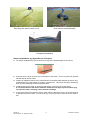
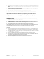
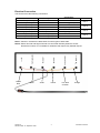
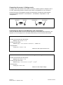
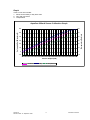
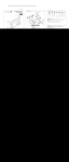
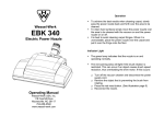
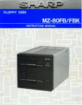
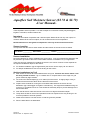
Aquaflex Soil Moisture Sensor (SI.78 & SI.79) -User ManualThese Aquaflex sensors provide a 4 to 20mA output for connection to third party dataloggers, irrigation controllers, weather stations etc. Important There are two models of Aquaflex with 4-20mA outputs. Model SI.78 has only one output, for moisture. Model SI.79 has two outputs, one for moisture and one for temperature. NOTE: References in this guide to temperature refer only to the model SI.79 sensor. Sensor Location It is important that the sensor serial number and the location of the sensor are recorded: Serial Number _____________ Date Installed _____________ Location _________________________________ Sensor Installation Recommendations for sensor installation are given below. Your local AQUAFLEX Distributor will be pleased to give advice about the most suitable method of installation for your application. There are two main methods for installing the sensors, the choice of which to uses depends on the required installation depth for the sensor. For shallow installation (eg turf applications) the sensor can be simply ‘slit’ into the turf. For deeper installations a trench must be dug for the sensor. Shallow Installations (eg Turf) Mark where the sensor is to be installed with a string line. Position the sensor where it can be easily located in future – eg on a marker line on a sports field or at the edge of a golf green marked by sight markers. Cut a slit to the desired depth (eg 75 to 100mm) for the sensor. A slightly larger cavity is needed for the electronics block at the cable end of the sensor. Prepare some method for running the round data cable between the sensor and its destination (eg a data logger or irrigation controller etc). This might be an additional long slit in the turf, or a shallow trench etc. This should be sufficiently deep to prevent damage to the buried data cable. Push the flat sensor cable into the slit in the turf on its edge to the desired depth. Tamp down the slits in the turf and sprinkle fine sand or topsoil into the slit, packing it in as much as possible to avoid air pockets. Water the turf well to ‘bed’ the sensor in. Roll the ground if possible Run the data cable to its destination. AF044-03 Revision Date: 14 September 2001 1 US Patent 5148125 Run string line and cut a slit in turf Push sensor to desired depth Completed Installation Deeper Installations (eg Agriculture or Vineyard) For deeper installations a trench should to be dug to the desired depth for the sensor Ensure there is a layer of loose soil in the bottom of the trench. This is to prevent air pockets beneath the flat sensor cable. Prepare an additional trench to accommodate the round data cable between the sensor and its destination (eg a data logger or irrigation controller etc). This trench should be sufficiently deep to prevent damage to the buried data cable. Install the flat sensor cable on its edge at the bottom of its trench as shown above. It is essential that the flat sensor cable be installed on its edge to prevent water lying on top of the cable, resulting in false moisture readings. Firmly pack loose soil around the sensor cable ensuring that there are no air pockets around or beneath the sensor cable. In some soils (eg. clay) it may help to water the soil to assist in this. AF044-03 Revision Date: 14 September 2001 2 US Patent 5148125 Carefully refill the trench taking care to keep the soil profile and density as close to its original state as possible. It is important that there are no air pockets within 150 mm (6 inches) of the sensor. Install the data cable in its trench and refill the trench, leaving excess cable coiled up in the trench below the logger/irrigation controller. Mark the location of the sensor so that it can be identified in the future. Refer to the installation hints on the final page for additional ideas to assist installation. After installation, allow time for the disturbed soil to settle before using the data from your Aquaflex Sensors. This can take some time depending on soil type and local conditions. The settling process can be accelerated by applying several heavy irrigations, ideally taking the soil to saturation each time. Installation Hints Always unroll the data cable. Pulling cables off the side of a roll results in the cable coiling, which makes it difficult to install in the trench. Install the data cable in a metal or plastic conduit if there is risk of damage from spiking etc. NOTE: The flat sensor cable must not be similarly protected. Ensure that the sensor cable is at least 150mm away from any foreign objects. When installing several sensors at one site, only one power supply is required for all sensors. All sensor power and ground connections are connected to the power supply terminals. General The 4-20mA sensors provide a signal that represents soil moisture in volumetric percent and an optional signal (model SI.79 only) that represents the soil temperature in degrees Celsius. The output signals are currents in the range 4 to 20mA representing soil moisture of 0 to 60% or a temperature of -10°C to 50°C. The sensor can be configured to output a voltage instead of the 4 to 20mA current. The temperature sensor is located in the electronics module at the end of the flat cable and measures the soil temperature in the region of the module. While power is applied the sensor takes one measurement every minute. AF044-03 Revision Date: 14 September 2001 3 US Patent 5148125 Electrical Connection The sensors have the following connections. Wire Colour Description Connection Thick Red (White 1) Black (Black 1) Violet (White 3) Yellow (Black 3) Brown/Thin Red (White 4) Orange (Black 4) White (White 2) Blue (Black 2) Sensor Power Sensor Ground Moisture + Moisture Temperature + Temperature Factory Only Factory Only +Volts 0 Volts (ground) 4 – 20mA Signal ground 4 – 20mA Signal ground Do not connect Do not connect Cable Pairs Pair 1 Pair 2 Pair 3 Pair 4 Note 1: Colours in brackets are alternatives for some types of data cable. Thick Red Black AF044-03 Revision Date: 14 September 2001 Violet Yellow 4 Thin Red or Brown Temperature - Temperature + Moisture - Moisture + 0 volts (ground) + volts Note 2: Sensor Ground and Signal Ground are connected internally within the sensor, therefore this sensor is not suitable for situations that require fully isolated outputs. Orange US Patent 5148125 Connecting the sensor in Voltage mode In voltage mode 125 resistors are used to convert the 4-20mA signals to voltages of 0.5 to 2.5 volts, representing moisture content of 0% to 60% or temperature of -10°C and 50°C. Connect the sensor to the logger/controller as shown above, but with the 125 resistors connected between "Moisture +" and "Moisture -", and between “Temperature +” and “Temperature –“: Moisture + Moisture - Temperature + 125 Temperature - 125 Converting the Signal to Soil Moisture and Temperature There are two methods to convert the output signals into soil moisture and temperature. The simplest is to use the graph on the next page, alternatively use the formulas shown below: Standard 4 to 20mA Output For sand, silt and sandy and silty loams: Moisture (%) = 3.75 x C - 15 For clay and clay loams: 2 3 Moisture (%) = -14 + 2.87 x C + 0.214 x C - 0.0086 x C For temperature : Temp (°C) = 3.75 x C – 25 Where C is the output current in mA When a 125 ohm resistor is used to convert the signal to a voltage For sand, silt and sandy and silty loams: Moisture (%) = 30 x V - 15 For clay and clay loam soils: 2 3 Moisture (%) = -14 + 23 x V + 13.7 x V - 4.4 x V For temperature: Temp (°C) = 30 x V - 25 Where V is the Output voltage AF044-03 Revision Date: 14 September 2001 5 US Patent 5148125 Graph Three curves are included: 1. Sand, silt and sandy or silty loam soils 2. Clay and clay loams 3. Temperature. 60 60 50 50 40 40 30 30 20 20 10 10 0 0 -10 -10 4 5 6 7 8 9 10 11 12 13 14 15 16 17 18 19 20 Sensor Output (mA) sand/silt AF044-03 Revision Date: 14 September 2001 clay temperature 6 US Patent 5148125 Temperature (Celsius) Volumetric Soil Moisture (%) Aquaflex 4/20mA Sensor Calibration Graph Specification Power supply voltage 9 to 26 volts, DC Power supply current 10mA average, 150mA peak (for 60 milliseconds during measurement) plus current loops of up to 20mA each. Maximum load resistance 250 with 9 Volts supply 1 k with 24 Volts supply Time to measure 1 second after power is applied (max). Typically 0.8 seconds. Time between measurements 1 minute Sensor faults If a fault occurs, the sensor outputs special currents of less than 4mA as shown below: Current 0 mA 1 mA 2 mA 3 mA Fault condition A broken wire or total failure of the sensor. Check the wiring and repair. Contact your distributor if wires are intact. Moisture reading out of expected range. If this output continues, contact your distributor. Low battery or supply voltage. Replace the batteries or check power supply. Critical sensor settings have been lost. Contact your distributor. Conditions of Use Aquaflex must be installed as specified. Use of Aquaflex data is entirely at the discretion of the user and should therefore be subject to current best practice principles of soil moisture management and agronomic management. Neither Streat Instruments nor its Distributors shall be liable (whether in contract, tort or otherwise) for any loss (including but not limited to loss of profits and consequential loss) of any kind whatever arising out of any published material or in connection with the performance or use of Aquaflex. The serial number marked on each Aquaflex Sensor must be recorded and quoted for warranty claims. Streat Instruments Limited PO Box 24071 Christchurch New Zealand Ph: +64 3 384 8900 Fax: +64 3 384 8901 [email protected] www.streatsahead.com AF044-03 Revision Date: 14 September 2001 Envirofactors Limited 3 Water Lane Bradford BD1 2JL United Kingdom Ph: +44 1274 733 145 Fax: +44 1274 732 410 [email protected] www.envirofactors.com 7 Streat Moisture Solutions (USA), LLC PMB 304 516-D River Hwy Mooresville, NC 28117-6830 USA Ph: +1 704 718 7945 [email protected] www.streatsahead.com US Patent 5148125