1
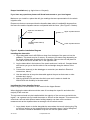
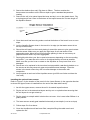
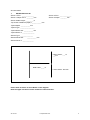
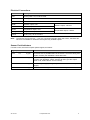
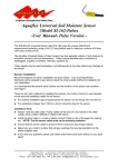
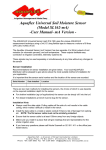
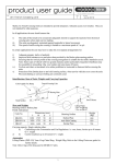
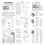
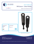
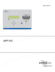
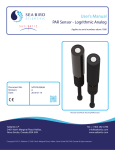
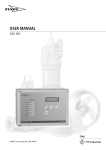
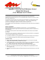
Aquaflex Universal Soil Moisture Sensor (Model SI.162-mA) -User Manual- mA Version The AQUAFLEX Universal Sensor (part # SI.162) uses the unique AQUAFLEX measurement technique using a 3m (10’) long flexible tape to measure a volume of 6 litres (370 cubic inches) of soil. The Aquaflex Universal Sensor (mA Version) has two separate 4 to 20mA outputs of soil moisture (in volumetric percent), and soil temperature. These outputs facilitate easy connection to dataloggers, irrigation controllers, telemetry systems etc. These signals may be used separately or simultaneously at any time without any changes to the sensor Sensor Installation Recommendations for sensor installation are given below. Your local AQUAFLEX Distributor will be pleased to give advice about the most suitable method of installation for your application. It is important that the sensor serial number and the location of the sensor are recorded – see Page 6 There are two main methods for installing the sensors, the choice of which to use depends on the required installation depth for the sensor. For shallow installation (eg turf applications) the sensor can be simply ‘slit’ into the turf. For installations deeper than 100mm a trench should be dug for the sensor. Installation Hints Always unroll the data cable. Pulling cables off the side of a roll results in the cable coiling, which makes it difficult to install in the trench. Install the data cable in a metal or plastic conduit if there is risk of damage from spiking etc. NOTE: The flat sensor cable must not be similarly protected. Ensure that the sensor cable is at least 150mm away from any foreign objects. Make sure you install in a place that will give readings that are representative for the whole irrigation area. If you have any questions please call Streat Instruments (see footer below) or your local agent. Aquaflex NZ – a division of Streat Instruments Limited, 4a Expo Place, PO Box 24071, Christchurch, New Zealand Phone +64 3 384 8900 Fax +64 3 384 8901 [email protected] www.aquaflex.co.nz Shallow Installations (e.g. Turf) 1. Select and mark the position of the sensor with a string line. Position the sensor where it can be easily located in future – e.g. on a marker line on a sports field or in a position on a golf green marked by sight markers (e.g. between two known points). 2. Note: If the soil is sandy, it is easier to install the sensor when the soil is wet, because it holds together better. 3. With a turf cutter or sharp, flat blade, carefully cut a slit in the turf. 4. Carefully insert the sensor into the slit to the desired depth. Note: The sensor must be installed on its edge. 5. For the electronics block at the end of the sensor, carefully peel back sufficient turf to create a slightly larger and deeper cavity in which to bury the block. Fold the turf back. 6. Gently push from behind each side of the slit to close it. Pack from the sides to recreate original density and remove air pockets. 7. Repair and smooth as necessary. 8. Apply a liberal amount of irrigation/water to allow the sensor to bed in and remove air pockets. 9. Run the data cable in a slit or trench to the desired location (e.g. the Datalogger or Controller). Note: ensure that the cable is buried deep enough to avoid damage during maintenance. Run string line and cut a slit in turf Push sensor to desired depth Completed Installation AF-201-03 14 September 2014 2 Deeper Installations (e.g. Agriculture or Vineyard) If you have any questions please call Streat Instruments or your local agent. Make sure you install in a place that will give readings that are representative for the whole irrigation area. Please note that we recommend that the Aquaflex data cable is installed 90 degrees from the fence line and the Aquaflex sensor runs parallel with the fence. (See Figure 1.0 below). Fenceline Aquacom Unit attached to post Aquaflex Data Cable (3 to 20m) Upper Aquaflex Sensor Lower Aquaflex Sensor Figure 1 Aquaflex Installation Diagram Installing the data cable 1. Dig a data cable trench 400-500 mm deep from the base of the post out into the paddock. This trench may be 3 metres, 10 meters or 20 metres long depending on the length of data cable supplied with the Aquaflex. Remove the turf and place on one side of the trench and the soil on the opposite side. 2. Lay the data cable in the bottom of the trench and cover it with soil. Compact down with feet as you go so that the cable is flat and straight along the bottom of the trench. 3. Connect the sensor(s) to the datalogger or controller (see details in Electrical connections, below). 4. Use the cable ties to keep the data cable against the post so that cows or other animals don’t chew it. 5. Near the AQUAFLEX end leave the ditch open as it is easier to install the AQUAFLEX with flexibility in the data cable. Installing the Upper Aquaflex Sensor Refer to Figure 1 for the location of the trench for the Upper Sensor. When digging the data cable trench take note of how deep the topsoil is and where the majority of the roots are. The top sensor should only be installed within the majority of the root zone and within the topsoil – as a general rule we install the sensor to 300 mm at the deepest. This removes the effect that a sub soil with different water holding capacity can have on the moisture measurement as the Aquaflex takes an average over the whole sensor. 1. Lay a plastic sheet or similar alongside the area where the trench is being dug. Dig out the turf and lay on the opposite side from the plastic sheet. If soil is falling from the turf then it would be advisable to lay the turf onto the plastic sheet. AF-201-03 14 September 2014 3 2. Start at the shallow (box end). Dig down to 50mm. The box contains the thermometer so needs to sit at 100 mm depth to give a standard temperature reading. 3. Remove the soil in its natural layers/horizons and lay it out on the plastic sheet. Dig a sloping trench from 10cm to the bottom of the topsoil across the 3 metre length of the Aquaflex Sensor. Nominated depth 4. Once the trench has been dug make sure that the bottom of the trench is on an even slope. 5. Lay the Aquaflex Sensor down in the trench in its edge (so that water cannot sit on the top of the sensor). 6. Shovel the soil back into the trench placing it around the sensor to give good contact with the sensor. Make sure you apply the right layer of soil and stones in the appropriate order. Move the soil around before packing it down to ensure any air gaps have been filled in by loose aggregates. 7. Pack tightly with either your feet or post hole rammer depending on the surrounding soil profile – you want the soil to return to its original density as best as possible. Make sure that you don’t ram or stand on the Aquaflex as it may bend over or be damaged. 8. Stones are to be replaced in the trench as best as possible, not directly beside or on the sensor as this may cause air gaps and possible sensor damage. Place the stones in the trench where they will not cause damage to the sensor with compaction. 9. Insert a paver at each end of the Aquaflex sensor (put 200 mm further out than the ‘real’ end) Installing the optional lower sensor Refer to Figure 1 for the location of the trench for the Lower Sensor (in the opposite direction to where the Upper Sensor is installed from the end of the data cable trench). 1. As with the upper sensor, remove the soil in its natural layers/horizons. 2. Dig the soil out in the determined layers and lay out on a plastic sheet ensuring that the soil layers do not get mixed up. 3. Dig the trench to a depth which is below the root zone - this is most often 500mm in a grass pasture. 4. The lower sensor usually gets installed horizontally at one depth (ie not on a slope) 5. Follow steps 5 to 9 as above. 6. Once the Aquaflex trench has been filled, complete filling the cable trench and replace the turf. AF-201-03 14 September 2014 4 Helpful Pictures Soil removed and placed in three layers. AF-201-03 Top sensor installed to 250mm at the deep end. 14 September 2014 5 Documentation 1. AQUAFLEX Records Sensor 1 S/no.: ______________ Sensor 2 S/no.: ______________ Sensor 1 Depth: 50 to ________ mm Sensor 2 Depth: _______ mm Sensor Cable Length: _________ m Top sensor installed to (depth): ___________ mm Topsoil depth: ___________ mm Topsoil Type: _________________ Topsoil Stone size: ___________ mm Topsoil Stone %: ______________ Subsoil Type: _______________ Subsoil Stone size: ___________ mm Subsoil Stone %: _____________ Upper Sensor ___ to ___mm Data Cable ____ m Lower Sensor 500 mm Please draw an Arrow to show North on the diagram. Note the upper and lower can be installed in either direction. AF-201-03 14 September 2014 6 Converting the Signal to Soil Moisture or Temperature 4 - 20mA Outputs For sand, silt and sandy and silty loams: Moisture (%) = 3.75 x C - 15 For clay and clay loams: 2 3 Moisture (%) = -14 + 2.87 x C + 0.214 x C - 0.0086 x C For temperature : Temp (°C) = 3.75 x C – 25 Where C is the output current in mA. 60 60 50 50 40 40 30 30 20 20 Sand/Silt Clay 10 10 Temperature (ºC) Volumetric Soil Moisture (%) Aquaflex 4 - 20mA Sensor Calibration Graph Temperature 0 0 -10 -10 4 5 6 7 8 9 10 11 12 13 14 15 16 17 18 19 20 Sensor Output (mA) When a 125 Resistor is Used to Convert the 4 - 20mA Signal to a 0.5 to 2.5 volt Signal For sand, silt and sandy and silty loams: Moisture (%) = 30 x V - 15 For clay and clay loam soils: 2 3 Moisture (%) = -14 + 23 x V + 13.7 x V - 4.4 x V For temperature: Temp (°C) = 30 x V - 25 Where V is the output voltage. AF-201-03 14 September 2014 7 Electrical Connections Wire Colour Description Red Sensor power +ve, 6.0 to 26 Volts. Black Sensor ground, 0 Volts Violet Not Used White Moisture output, mA + Blue Moisture output, mA - Brown Temperature output, mA + Orange Temperature output, mA - Yellow Factory only, do not connect. Note: Moisture output, 4-20 mA. Temperature output, 4-20mA. The Sensor Ground and mA - cores are connected internally within the sensor, therefore this sensor is not suitable for situations that require fully isolated outputs. Sensor Fault Indicators If a fault occurs, the sensor outputs special signals, as follows: Signal (V across 125 load ) Fault condition 0mA 0V 0 ppm A broken wire or possible failure in the sensor. Check the wiring and repair. Contact your distributor if wires are intact. 1 mA 0.125 V 2.5 ppm Moisture reading out of expected range. If this output continues, contact your distributor. (Note: sensors will often give this output when in air, before burial – this is normal) 2 mA 0.250 V 5.0 ppm Low battery or supply voltage. Replace the batteries or check power supply. 3 mA 0.375 V 7.5 ppm Critical sensor settings have been lost. Contact your distributor. AF-201-03 14 September 2014 8 Specifications Power supply voltage +6.0 to +26 Volts, DC. Power supply current 10mA average, 150mA peak (for 60 milliseconds during measurement) plus two current loops of up to 20mA each. 4-20mA outputs Moisture Output 4-20mA representing the moisture range 0-60%. Temperature Output 4-20mA representing the temperature range -10 to 50 C. Maximum load resistance 250 with 9 Volts supply. 1 k with 24 Volts supply. The 4-20mA signals may be converted to voltage signals by connecting external resistors across the 4-20mA outputs. Using a 125 resistor results in a 0.5 to 2.5V range. Time to measure 1.5 seconds after power supplied (typical). 2 second maximum. Time between measurements 1 minute, if power applied constantly. Operating Temperature -10 to 40C (14 to 104F) Soil Moisture Measurement Range 0 to 60% volumetric moisture content Precision / Repeatability ± 0.5% volumetric moisture content Accuracy ± 2% volumetric moisture content Soil Temperature Measurement The temperature is measured at the body of the sensor, not along the moisture-sensing cable. Range -10 to 50C (14 to 122F) Accuracy ± 0.5C (0.9F) Conditions of Use Aquaflex must be installed as specified. Use of Aquaflex data is entirely at the discretion of the user and should therefore be subject to current best practice principles of soil moisture management and agronomic management. Neither Streat Instruments nor its Distributors shall be liable (whether in contract, tort or otherwise) for any loss (including but not limited to loss of profits and consequential loss) of any kind whatever arising out of any published material or in connection with the performance or use of Aquaflex. The serial number marked on each Aquaflex Sensor must be recorded and quoted for warranty claims. AF-201-03 14 September 2014 9 Streat Instruments 4A Expo Place PO Box 24071 Christchurch New Zealand Ph: +64 3 384 8900 Fax: +64 3 384 8901 [email protected] www.streatsahead.com AF-201-03 UK Office Garnett Group Unit 6 Great Russell Court Fieldhead Business Centre Bradford BD7 1JZ United Kingdom Ph: +44 1274 733 145 Fax: +44 1274 736358 [email protected] www.streatsahead.com 14 September 2014 10