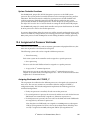
1
V+ Version 11.4
Release Notes
Incorporating the Release Notes
for V+ Versions 11.0 Through 11.4
®
030
VIS
VGB
SIO
DIO
VMI
FAIL
OK
1
1
2
2
3
3
4
OK
OK
1 2 3 4
ON
1 2 3 4 5 6 7 8
ON
4
D
R
I
V
E
A
R
S
4
2
2
/
4
8
5
F
P
/
M
C
P
V
I
D
E
O
V
I
D
E
O
B
U
S
B
U
S
ES
HPE
F1
DE1
F2
DE2
F3
DE3
F4
DE4
E
N
C
O
D
E
R
M
O
N
I
T
O
R
PASS
I
N
P
U
T
S
I
N
P
U
T
S
1
#1
2
3
M
A
C
H
I
N
E
4
1 2 3 4
ON
R
S
2
3
2
/
T
E
R
M
O
U
T
P
U
T
S
#2
P
O
I
N
T
E
R
KEYBOARD
C
A
M
E
R
A
S
/
S
T
R
O
B
E
S
S
E
R
V
O
O
U
T
P
U
T
S
®
adept
technology, inc.
V+ Version 11.4
Release Notes
Incorporating the Release Notes
for V+ Versions 11.0 Through 11.4
®
030
VIS
VGB
SIO
DIO
VMI
FAIL
OK
1
1
2
2
3
3
4
OK
1 2 3 4
ON
1 2 3 4 5 6 7 8
ON
4
OK
D
R
I
V
E
A
R
S
4
2
2
/
4
8
5
F
P
/
M
C
P
V
I
D
E
O
V
I
D
E
O
B
U
S
B
U
S
ES
HPE
F1
DE1
F2
DE2
F3
DE3
F4
DE4
E
N
C
O
D
E
R
M
O
N
I
T
O
R
PASS
I
N
P
U
T
S
I
N
P
U
T
S
1
#1
2
3
M
A
C
H
I
N
E
4
1 2 3 4
ON
R
S
2
3
2
/
T
E
R
M
O
U
T
P
U
T
S
#2
P
O
I
N
T
E
R
KEYBOARD
C
A
M
E
R
A
S
/
S
T
R
O
B
E
S
S
E
R
V
O
O
U
T
P
U
T
S
®
adept
technology, inc.
00961-04120, Rev. A
February 1997
®
150 Rose Orchard Way • San Jose, CA 95134 • USA • Phone (408) 432-0888 • Fax (408) 432-8707
Otto-Hahn-Strasse 23 • 44227 Dortmund • Germany • Phone 0231/75 89 40 • Fax 0231/75 89 450
adept
technology, inc.
11, Voie la Cardon • 91126 • Palaiseau • France • Phone (1) 69.19.16.16 • Fax (1) 69.32.04.62
1-2, Aza Nakahara, Mitsuya-Cho • Toyohashi, Aichi-Ken • 441-31 • Japan • (0532) 65-2391 • Fax (0532) 65-2390
The information contained herein is the property of Adept Technology, Inc., and
shall not be reproduced in whole or in part without prior written approval of
Adept Technology, Inc. The information herein is subject to change without notice
and should not be construed as a commitment by Adept Technology, Inc. This
manual is periodically reviewed and revised.
Adept Technology, Inc., assumes no responsibility for any errors or omissions in
this document. Critical evaluation of this manual by the user is welcomed. Your
comments assist us in preparation of future documentation. A form is provided at
the back of the book for submitting your comments.
Copyright © 1996 by Adept Technology, Inc. All rights reserved.
The Adept logo is a registered trademark of Adept Technology, Inc.
Adept, AdeptOne, AdeptOne-MV, AdeptThree, AdeptThree-MV, PackOne, PackOne-MV,
HyperDrive, Adept 550, Adept 550 CleanRoom, Adept 1850, Adept 1850XP,
A-Series, S-Series, Adept MC, Adept CC, Adept IC, Adept OC, Adept MV,
AdeptVision, AIM, VisionWare, AdeptMotion, MotionWare, PalletWare,
AdeptNet, AdeptFTP, AdeptNFS, AdeptTCP/IP, AdeptForce, AdeptModules,
and V+ are trademarks of Adept Technology, Inc.
Any trademarks from other companies used in this publication are the property
of those respective companies.
Printed in the United States of America
TOC
Table of Contents
Introduction 9
1.1
Overview
. . . . . . . . . . . . . . . . . . . . . . . . . . . . . . . . . . . . . . . .
9
1.2
Book Parts
. . . . . . . . . . . . . . . . . . . . . . . . . . . . . . . . . . . . . . . .
9
1.3
Related Manuals
1.4
. . . . . . . . . . . . . . . . . . . . . . . . . . . . . . . . . . .
Standard Manuals . . . . . . . . . . . . . . . . . . . . . . . . . . . . . . . . . .
Other Adept Product Manuals . . . . . . . . . . . . . . . . . . . . . . . . . .
Optional V+ Developer’s Manuals . . . . . . . . . . . . . . . . . . . . . . . .
10
10
11
Conventions
11
. . . . . . . . . . . . . . . . . . . . . . . . . . . . . . . . . . . . .
.
.
.
.
.
11
12
13
13
14
. . . . . . . . . . . . . . . . . . . . . . . . . . . . . . .
14
Changes to V+ Monitor Commands . . . . . . . . . . . . . . . . . . . . . .
Changes to V+ Programming Keywords . . . . . . . . . . . . . . . . . . . .
Changes to V+ Keywords for the AdeptVision Product . . . . . . . . . .
14
16
20
Notes, Cautions, and Warnings . . . . . . . . .
Typographic Conventions . . . . . . . . . . . . .
Keyboard Conventions . . . . . . . . . . . . . . .
Selecting, Choosing, Pressing, and Performing
Abbreviations . . . . . . . . . . . . . . . . . . . . .
1.5
9
Summary of Changes
. . . .
. . . .
. . . .
. . .
. . . .
.
.
.
.
.
.
.
.
.
.
.
.
.
.
.
.
.
.
.
.
.
.
.
.
.
.
.
.
.
.
.
.
.
.
.
.
.
.
.
.
.
.
.
.
.
.
.
.
.
.
.
.
.
.
.
Part 1 23
Notes for V+ Version 11.4 23
How to Upgrade 25
2.1
Compatibility Issues
2.2
Upgrading to V+ Version 11.4
. . . . . . . . . . . . . . . . . . . . . . . . . . . . . . . .
25
. . . . . . . . . . . . . . . . . . . . . . . . . .
26
Saving Current Configuration Data–Version 11.0 . . . . . . . . . . . . . .
Saving Current Configuration Data–Versions 11.1, 11.2, and 11.3 . . .
Installing the New V+ Version 11.4 System . . . . . . . . . . . . . . . . . . .
Applying Saved Robot and Encoder Configuration Data . . . . . . . .
26
28
29
30
Changes to the V+ Operating System and Language Version 11.4 31
V+ Language User’s Guide
ii
3.1
New Functionality
. . . . . . . . . . . . . . . . . . . . . . . . . . . . . . . . . .
31
3.2
New Robot Module
. . . . . . . . . . . . . . . . . . . . . . . . . . . . . . . . .
33
3.3
Networking Changes
. . . . . . . . . . . . . . . . . . . . . . . . . . . . . . .
33
3.4
Clarification of Event Triggers
3.5
Correction to the GAIN.SET Instruction
3.6
Miscellaneous Changes
. . . . . . . . . . . . . . . . . . . . . . . . . .
33
. . . . . . . . . . . . . . . . . . . .
34
. . . . . . . . . . . . . . . . . . . . . . . . . . . . .
34
Part 2 35
Notes for V+ Version 11.3 35
Changes to the V+ Operating System and Language Version 11.3 37
4.1
4.2
4.3
4.4
General Changes
. . . . . . . . . . . . . . . . . . . . . . . . . . . . . . . . . .
37
Enhanced COPY and EDIT Monitor Commands . . . . . . . . . . . . . . .
Clarification of the PROFILE Switch . . . . . . . . . . . . . . . . . . . . . . .
Increased Number of Menu Bar Items . . . . . . . . . . . . . . . . . . . . .
37
37
37
Changes for European Certification (CE)
38
. . . . . . . . . . . . . . . . . .
New Terminology Relating to the VFP and MCP . . . . . . . . . . . . . .
New Startup Messages . . . . . . . . . . . . . . . . . . . . . . . . . . . . . . .
Enabling High Power . . . . . . . . . . . . . . . . . . . . . . . . . . . . . . . . .
Disabling High Power . . . . . . . . . . . . . . . . . . . . . . . . . . . . . . . .
Enhanced ID Monitor Command . . . . . . . . . . . . . . . . . . . . . . . .
New AUTO.POWER.OFF System Switch . . . . . . . . . . . . . . . . . . . . .
Hard and Soft Envelope Errors . . . . . . . . . . . . . . . . . . . . . . . . . .
Changes in Manual Mode . . . . . . . . . . . . . . . . . . . . . . . . . . . . .
The STEP Button and Limits to Program-Controlled Motion . . . . . . . .
Elimination of Program Interlocks
Enhanced DO, EXECUTE, PROCEED, RETRY, and WAIT.START Monitor
Commands . . . . . . . . . . . . . . . . . . . . . . . . . . . . . . . . . . . .
New SAFE_UTL Utility for Category 3 Systems . . . . . . . . . . . . . . . . .
Enhanced STATE Function . . . . . . . . . . . . . . . . . . . . . . . . . . . . .
Reserved Digital Signals . . . . . . . . . . . . . . . . . . . . . . . . . . . . . . .
38
38
39
42
43
43
43
43
44
General Motion Changes
. . . . . . . . . . . . . . . . . . . . . . . . . . . .
45
Clarification of the GAIN.SET Program instruction . . . . . . . . . . . . . .
Altered PAYLOAD Program Instruction . . . . . . . . . . . . . . . . . . . . .
New Range for the Encoder Roll-Over Value . . . . . . . . . . . . . . . .
45
46
46
Changes for the AdeptMotion VME Product
46
. . . . . . . . . . . . . . . .
Change to the Robot Option Word (All Modules) . .
Enhanced 5/6-Axis PUMA Robot Module (EPU) . . . .
New Coupled-Axes X/Y/Z/Theta Robot Module (CAR)
Enhanced T12 Robot Module (T12) . . . . . . . . . . . .
Enhanced X/Y/3(Z/Theta) Robot Module (XY3) . . . .
Z/Theta Heads Increased from 3 to 4 . . . . . . . .
Optional Split-Axis Capability for the y-axis . . . .
Collision Detection and Avoidance . . . . . . . . .
. . .
. . .
. .
. . .
. . .
. . .
. . .
. . .
.
.
.
.
.
.
.
.
.
.
.
.
.
.
.
.
.
.
.
.
.
.
.
.
.
.
.
.
.
.
.
.
.
.
.
.
.
.
.
.
.
.
.
.
.
.
.
.
.
.
.
.
.
.
.
.
.
.
.
.
.
.
.
.
44
45
45
45
46
46
47
47
48
48
48
48
Table of Contents
4.5
Changes for the FlexFeeder Product
4.6
Changes for the AdeptVision Product
4.7
Changes for the AdeptNet Product
iii
. . . . . . . . . . . . . . . . . . . . .
48
. . . . . . . . . . . . . . . . . . . .
49
. . . . . . . . . . . . . . . . . . . . . .
49
Increased Number of NFS Mounts . . . . . . . . . . . . . . . . . . . . . . . .
Enhanced NET Command . . . . . . . . . . . . . . . . . . . . . . . . . . . . .
49
49
Changes to the Utility Disk 51
5.1
Table of Changes
5.2
Changes to the ADV_CAL Utility
5.3
. . . . . . . . . . . . . . . . . . . . . . . . . . . . . . . . . .
51
. . . . . . . . . . . . . . . . . . . . . . . .
52
New Robot Module Supported . . . . . . . . . . . . . . . . . . . . . . . . . .
52
Changes to the CONFIG_C Utility
52
. . . . . . . . . . . . . . . . . . . . . . .
.
.
.
.
.
52
53
53
53
53
. . . . . . . . . . . . . . . . . . . . . . . .
53
Correction to Copying Protected Files . . . . . . . . . . . . . . . . . . . . .
Correction to Copying/Deleting Files with No Date Information . . . .
53
53
Changes to the FORMAT Utility
. . . . . . . . . . . . . . . . . . . . . . . . .
54
Change to Format for Very Large Hard Drives . . . . . . . . . . . . . . . .
54
Changes to the FTP Utilities
. . . . . . . . . . . . . . . . . . . . . . . . . . . .
54
Improvements to the FTP_CLNT Utility . . . . . . . . . . . . . . . . . . . . . .
Improvements to the FTP_SRVR Utility . . . . . . . . . . . . . . . . . . . . . .
54
54
5.7
Changes to the PROFILER Utility
. . . . . . . . . . . . . . . . . . . . . . . . .
54
5.8
New SAFE_UTL Utility
. . . . . . . . . . . . . . . . . . . . . . . . . . . . . . . .
54
5.9
Changes to the SUCURE Utility
Compatibility Change . . . . . . . . .
New POWER_TIMEOUT Statement . .
New Checking for TASKS Statements
Updated Built-In Copy of DISKCOPY
Recognition of New System Options
5.4
5.5
5.6
Changes to the DISKCOPY Utility
.
.
.
.
.
.
.
.
.
.
.
.
.
.
.
.
.
.
.
.
.
.
.
.
.
.
.
.
.
.
.
.
.
.
.
.
.
.
.
.
.
.
.
.
.
.
.
.
.
.
.
.
.
.
.
.
.
.
.
.
.
.
.
.
.
.
.
.
.
.
.
.
.
.
.
.
.
.
.
.
.
.
.
.
.
.
.
.
.
.
.
.
.
.
.
.
.
.
.
.
. . . . . . . . . . . . . . . . . . . . . . . . .
55
. . . . . . . . . . . . . . . . . . . . . . . . . . .
55
. . . . . . . . . . . . . . . . . . . . . . . . . . . . . . .
55
5.10 Changes to the SFUTIL Utility
Compatibility Change
.
.
.
.
.
5.11 Changes to the SPEC Utility
. . . . . . . . . . . . . . . . . . . . . . . . . . .
Compatibility Change . . . . . . . . . . . . . . . . . . . . .
New Menu Item for Acceleration Feedforward . . . . .
Joint-4 Tuning for Adept Robots . . . . . . . . . . . . . . .
Removal of Data Items . . . . . . . . . . . . . . . . . . . . .
New Menu Item for Maximum Torque in Manual Mode
New Menu Item for Collision Detection . . . . . . . . . .
.
.
.
.
.
.
.
.
.
. .
.
.
.
.
.
.
.
.
.
.
.
.
.
.
.
.
.
.
.
.
.
.
.
.
.
.
.
.
.
.
.
.
.
.
.
.
.
.
.
.
.
.
.
.
.
.
.
.
55
55
55
55
55
56
56
V+ Language User’s Guide
iv
A New and Modified System Messages 57
B Linear Compensation for the Enhanced PUMA Robot Module 63
C Licenses 67
Part 3 73
Notes for V+ Version 11.2 73
Enhancements to the V+ Operating System and Language Version 11.2 75
6.1
General Enhancements
. . . . . . . . . . . . . . . . . . . . . . . . . . . . . .
.
.
.
.
.
.
75
75
75
76
76
76
. . . . . . . . . . . . . . . . . . . . . . . .
77
Single Boot Disk . . . . . . . . . . . . .
Information for General Users .
Information for Advanced Users
New CD Monitor Command . . . .
Enhanced DEBUG command . . . .
Enhanced SEE Command . . . . . .
6.2
General Motion Enhancements
. . .
. . .
. .
. . .
. . .
. . .
.
.
.
.
.
.
.
.
.
.
.
.
.
.
.
.
.
.
.
.
.
.
.
.
.
.
.
.
.
.
.
.
.
.
.
.
.
.
.
.
.
.
.
.
.
.
.
.
.
.
.
.
.
.
.
.
.
.
.
.
.
.
.
.
.
.
Changes Specific to Adept Robot Systems
.
.
.
.
.
.
.
.
.
.
.
.
.
.
.
.
.
.
.
.
.
.
.
.
.
.
.
.
.
.
.
.
.
.
.
.
.
.
.
.
.
.
.
.
.
.
.
.
.
.
.
.
.
77
77
78
78
78
. . . . . . . . . . . . . . . . .
78
New Calibration System . . . . . . . . . . . . . . . . . . . . .
Change to the CALIBRATE Monitor Command . . . .
EXECUTE/C Monitor Command and Program Instruction
Parameters for S-Curve Trajectories . . . . . . . . . . . . . .
New Algorithm for Tolerance Checking . . . . . . . . . . .
6.3
75
.
.
.
.
.
.
.
.
.
.
.
.
.
.
.
.
.
.
.
.
.
.
.
.
.
.
.
.
.
.
.
.
.
.
.
.
.
.
.
.
78
New Digital I/O Signals . . . . . . . . . . . . . . . . . . . . . . . . . . . . . . .
Enhancements to the ID Monitor Command and Real-Valued Function 79
80
Changes to the SCA Robot Module . . . . . . . . . . . . . . . . . . . . . .
6.4
Customizing the Calibration Routine . . . .
Enhancement to the JTS Robot Module . .
Enhancements to the PUMA Robot Module
Changes to the SPEC Utility . . . . . . . . . .
Changes for the T12 Robot Module . .
Modified ROBOT.OPR Instruction . . . . . . .
6.5
. . . . . . . . . . .
80
.
.
.
.
.
.
.
.
.
.
.
.
80
80
80
81
81
81
. . . . . . . . . . . . . . . .
82
Changes Specific to the AdeptMotion VME Product
Enhancements for the AdeptVision Product
D New and Modified Keywords 83
Part 4 87
Notes for V+ Version 11.1 87
Manual Updates 89
. . .
. . .
. .
. . .
. . .
. . .
.
.
.
.
.
.
.
.
.
.
.
.
.
.
.
.
.
.
.
.
.
.
.
.
.
.
.
.
.
.
.
.
.
.
.
.
.
.
.
.
.
.
.
.
.
.
.
.
.
.
.
.
.
.
.
.
.
.
.
.
.
.
.
.
.
.
.
.
.
.
.
.
.
.
.
.
.
.
Table of Contents
7.1
V+ Language User’s Guide
v
. . . . . . . . . . . . . . . . . . . . . . . . . . . .
89
Inter-Processor Communication on the VMEbus . . . . . . . . . . . . . .
S-Curve Trajectory Generation . . . . . . . . . . . . . . . . . . . . . . . . . .
Changes in Floating-Point Implementation . . . . . . . . . . . . . . . . . .
89
89
89
7.2
V+ Language Reference Guide
90
7.3
Instructions for Adept Utility Programs
. . . . . . . . . . . . . . . . . . . . . . . .
. . . . . . . . . . . . . . . . . . . .
90
Changes to V+: 10.x to 11.0 101
8.1
Summary of Changes
. . . . . . . . . . . . . . . . . . . . . . . . . . . . . .
101
.
.
.
.
.
101
102
103
103
103
. . . . . . . . . . . . . . . . . . . . . . .
103
New Commands . . . . . . . . . . . . . . . . . . . . . . . . . . . . . . . . . .
Altered Commands . . . . . . . . . . . . . . . . . . . . . . . . . . . . . . . .
103
103
8.3
Changes to V+ Programming Keywords
. . . . . . . . . . . . . . . . . .
104
8.4
Compatibility Issues
. . . . . . . . . . . . . . . . . . . . . . . . . . . . . . .
105
General System-Level Additions . . . . . . .
General Programming Language Additions
Command Line . . . . . . . . . . . . . . . . . .
Digital I/O . . . . . . . . . . . . . . . . . . . . . .
Analog I/O . . . . . . . . . . . . . . . . . . . . .
8.2
Changes to Monitor Commands
. .
.
. .
. .
. .
.
.
.
.
.
.
.
.
.
.
.
.
.
.
.
.
.
.
.
.
.
.
.
.
.
.
.
.
.
.
.
.
.
.
.
.
.
.
.
.
.
.
.
.
.
.
.
.
.
.
.
.
.
.
.
Changes to AdeptVision:10.x to 11.0 107
9.1
Image Region Changes
. . . . . . . . . . . . . . . . . . . . . . . . . . . .
107
9.2
New Vision Tool Features
. . . . . . . . . . . . . . . . . . . . . . . . . . . .
108
9.3
General Performance Enhancements
9.4
. . . . . . . . . . . . . . . . . . .
108
Other New Features
. . . . . . . . . . . . . . . . . . . . . . . . . . . . . . . .
109
Compatibility Issues
. . . . . . . . . . . . . . . . . . . . . . . . . . . . . . .
109
Summary of Incompatible Syntaxes
Spelling Correction, V.SYNC.STROBE
. . . . . . . . . . . . . . . . . . . . .
. . . . . . . . . . . . . . . . . . . . .
110
110
Changes to AdeptMotion: 10.x to 11.0 119
10.1 Changes to AdeptMotion Servo Parameters
. . . . . . . . . . . . . . .
.
.
.
.
.
.
.
119
119
119
120
120
120
120
. . . . . . . . . . . . . . . . . . . . . . . . .
120
Changes to Loop Gain . . . . . . . . . . . . . . . . . . . . .
Changes to Drive Enable Sequence . . . . . . . . . . . .
Changes to Processing of Error *Duty Cycle Exceeded*
*Duty-cycle Exceeded* DAC Limit . . . . . . . . . . .
*Duty-cycle exceeded* Filter Parameter . . . . . .
User-Selectable Servo Rate . . . . . . . . . . . . . . . . . .
Changes to Calibration Parameters . . . . . . . . . . . .
10.2 Changes to Device Modules
119
. . .
. . .
. .
. . .
. . .
. . .
. . .
Device Module Distribution and Licenses . . . . . . . . . .
Device Module Documentation . . . . . . . . . . . . .
Changes to PUMA Device Module (ID=14) . . . . . . . . .
Note for customers upgrading existing PUMA robots:
Change to SCARA Device Module (ID=6) . . . . . . . . .
.
.
.
.
.
.
.
.
.
.
.
.
.
.
. . . .
. . . .
. . . .
. . .
. . . .
.
.
.
.
.
.
.
.
.
.
.
.
.
.
.
.
.
.
.
.
.
.
.
.
.
.
.
.
.
.
.
.
.
.
.
.
.
.
.
.
.
120
120
121
121
122
V+ Language User’s Guide
vi
Note for customers upgrading existing robots: . . . . . . .
Change to Theta-Parallelogram Device Module (T12, ID=10)
Note for customers upgrading existing robots: . . . . . . .
Changes to Enhanced Gantry Module (EGN, ID=19) . . . . .
Changes to Coordinated-Joint-Control Module (JTS, ID=15)
Changes to Enhanced XYZ Module (EXY, ID = 18) . . . . . . .
.
.
.
.
.
.
122
122
122
122
122
123
. . . . . . . . . . . . . . . .
123
. . . . . . . . . . . . . . . . . . . . . .
123
10.3 Changes to V+ Functions and Parameters
10.4 Changes to the SPEC.V2 program
10.5 Changes to AdeptMotion Device Module Documents
.
.
.
.
.
.
.
.
.
.
.
.
.
.
.
.
.
.
.
.
.
.
.
.
. . . . . . . .
123
123
Documentation Correction, Rotational Axes . . . . . . . . . . . . . . . .
Enhanced Gantry Robot Device Module Document and Enhanced XYZ/
123
Theta Device Module Document . . . . . . . . . . . . . . . . . . . . .
. . . . . . . . . . . . . . . . . . . . . . .
124
. . . . . . . . . . . . . . . . . . . . .
124
. . . . . . . . . . . . . . . . . . . . . . . . . . .
131
Major Additions . . . . . . . . . . . . . . . . . . . . . . . . . . . . . . . . . . .
General System-Level Additions . . . . . . . . . . . . . . . . . . . . . . . .
General Programming Language Additions . . . . . . . . . . . . . . . .
131
131
132
10.6 Miscellaneous Motion Changes
10.7 New and Changed Error Messages
+
Changes in V 11.1 131
11.1 Summary of New Features
11.2 Changes to Monitor Commands
. . . . . . . . . . . . . . . . . . . . . . .
132
.
.
.
.
.
.
.
.
.
.
.
132
132
132
132
133
133
133
134
134
134
135
. . . . . . . . . . . . . . . . . .
135
. . . . . . . . . . . . . . . . . . . . . . . . . .
135
. . . . . . . . . . . . . . . . . . . . . . . . . . . .
135
Altered Keywords . . . . . . . . . . . . . . . . . . . . . . . . . . . . . . . . . .
VCORRELATE Program Instruction . . . . . . . . . . . . . . . . . . . . .
VTRAIN.MODEL Program Instruction . . . . . . . . . . . . . . . . . . .
135
135
136
New Commands . . . . . . . . . . . . . . . . . . . . . . . . .
ESTOP Monitor Command and Program Instruction
Altered Commands . . . . . . . . . . . . . . . . . . . . . . .
DIRECTORY . . . . . . . . . . . . . . . . . . . . . . . . . . .
DISABLE POWER . . . . . . . . . . . . . . . . . . . . . . .
FCOPY . . . . . . . . . . . . . . . . . . . . . . . . . . . . .
FORMAT . . . . . . . . . . . . . . . . . . . . . . . . . . . .
LISTR/LISTS/LISTL . . . . . . . . . . . . . . . . . . . . . . . .
LOAD . . . . . . . . . . . . . . . . . . . . . . . . . . . . . .
MDIRECTORY . . . . . . . . . . . . . . . . . . . . . . . . .
SEE Editor Inserts Global Module Automatically . .
11.3 Changes to V+ Programming Keywords
11.4 Changes to Error Messages
11.5 Changes to AdeptVision
. .
.
. .
. .
. .
. .
. .
. .
. .
. .
. .
.
.
.
.
.
.
.
.
.
.
.
.
.
.
.
.
.
.
.
.
.
.
.
.
.
.
.
.
.
.
.
.
.
.
.
.
.
.
.
.
.
.
.
.
.
.
.
.
.
.
.
.
.
.
.
.
.
.
.
.
.
.
.
.
.
.
. . . . . . . . . . . . . . . . . . .
136
Changes to Trajectory Generation Algorithm . . . . . . . . . . . . . . .
“AS” Device Module now on V+ System Disk (ID = 1, 6, 7) . . . . . . .
Manual Control Pendant Changes . . . . . . . . . . . . . . . . . . . . . .
136
137
137
11.6 Changes Affecting Adept Robot Users
. . . . . . . . . . . . . . . . . . .
137
Configurable V+ Trajectory Cycle Rates . . . . . . . . . . . . . . . . . . .
137
11.7 Changes Affecting AdeptMotion Users
Table of Contents
vii
Predicted Belt Position Returned by DEVICE and BELT Functions
Limits on “Minimum Motion Times” . . . . . . . . . . . . . . . . . . .
ALTER Program Instruction . . . . . . . . . . . . . . . . . . . . . . . .
STATE Real-valued Function . . . . . . . . . . . . . . . . . . . . . . .
Continuous-Turn Axes . . . . . . . . . . . . . . . . . . . . . . . . . . . . . .
NOT.CALIBRATED Parameter Range Changed . . . . . . . . . . . . .
Default Task Priorities . . . . . . . . . . . . . . . . . . . . . . . . . . . . . . .
New Kinematic Device Module: “X/Z Stacker Robot” (XZ, ID = 23)
Changes to Enhanced XYZ/Theta Module (EXY, ID = 18) . . . . . . .
Changes to Trajectory Generation Algorithm . . . . . . . . . . . . . .
Servo Changes Affecting Compatibility From 11.0 to 11.1 . . . . . .
Servo Changes Affecting Compatibility From 10.x to 11.1 . . .
Integrator Value Now Backed Up . . . . . . . . . . . . . . . . . . . . . .
Increased Number of Servo Joints per CPU Boards . . . . . . . . . .
.
.
.
.
.
.
.
.
.
.
.
.
.
137
137
137
138
138
138
138
138
140
140
140
141
141
142
. . . . . . . . . . . . . . . . . . . . .
142
. . . . . . . . . . . . . . . . . . . . . . . . . . . . . . .
142
Clarification of WAIT.EVENT Operation . . . . . . . . . . . . . . . . . . . .
Change to VME Memory Map . . . . . . . . . . . . . . . . . . . . . . . . .
System/User Task Priority Tables . . . . . . . . . . . . . . . . . . . . . . . . .
142
143
143
11.8 Changes to Adept Utility Programs
11.9 Programming Notes
Multiple-Processor Systems 145
12.1 Processor/Memory Requirements for Motion Systems
. . . . . . . . .
145
.
.
.
.
.
.
.
.
.
.
.
.
145
146
146
147
147
147
. . . . . . . . .
147
Standard AdeptVision . . . . . . . . . . . . . . . . . . . . . . . . . . . . . . .
Dual AdeptVision . . . . . . . . . . . . . . . . . . . . . . . . . . . . . . . . . .
147
148
Servo Processing Requirement . . . . . . . . . . . . . . .
Number of Servos Allocated per Processor Board
Trajectory Generation and MOVE Instructions . . . . .
Peripheral Drivers . . . . . . . . . . . . . . . . . . . . . . . .
Conveyor Belt Encoders . . . . . . . . . . . . . . . . . . .
Force Sensors . . . . . . . . . . . . . . . . . . . . . . . . . .
.
.
.
.
.
.
12.2 Processor/Memory Requirements for Vision Systems
.
.
.
.
.
.
.
.
.
.
.
.
.
.
.
.
.
.
.
.
.
.
.
.
.
.
.
.
.
.
.
.
.
.
.
.
.
.
.
.
.
.
. . . . . . . . . . . . . . . . . . .
148
.
.
.
.
.
.
.
.
148
148
148
149
. . . . . . . . . . . . . . . . . . . .
149
. . . . . . . . . . . . . . . . . . . .
149
. . . . . . . . . . . . . . . . . . . . . . . . . . . . . . . . . . . . . .
157
12.3 Configuration of the Processor Boards
Processor Board Locations . . . . . . . .
Slot Ordering of Processor Boards . . .
Processor Board Addressing . . . . . . .
System Controller Functions . . . . . . .
12.4 Assignment of Processor Workloads
Assigning Workloads with CONFIG_C
.
.
.
.
.
.
.
.
.
.
.
.
.
.
.
.
.
.
.
.
.
.
.
.
.
.
.
.
.
.
.
.
.
.
.
.
.
.
.
.
.
.
.
.
.
.
.
.
.
.
.
.
.
.
.
.
.
.
.
.
.
.
.
.
.
.
.
.
.
.
.
.
Multiple V+ Systems 157
13.1 Overview
Requirements . . . . . . . . . . . . . . . . . . . . . . . . . . . . . . . .
Monitor Commands and Multiple V+ Systems . . . . . . . . . . . . .
Using Autostart With Multiple-V+ systems . . . . . . . . . . . . . .
Multiple V+ Systems—Accessing the Command Prompt . . .
.
.
.
.
.
.
.
.
157
157
158
158
viii
V+ Language User’s Guide
13.2 Inter-System Communications
. . . . . . . . . . . . . . . . . . . . . . . .
158
.
.
.
.
.
.
.
.
159
160
160
160
. . . . . . . . . . . . . . . . . . . .
161
. . . . . . . . . . . . . . . . . . . . . . . . . . . . . . . .
169
Shared Data . . . . . . . .
IOTAS and Data Integrity
Efficiency Considerations
Digital I/O . . . . . . . . . .
.
.
.
.
.
.
.
.
.
.
.
.
.
.
.
.
.
.
.
.
.
.
.
.
.
.
.
.
.
.
.
.
13.3 Restrictions With Multiple Processors
.
.
.
.
.
.
.
.
.
.
.
.
.
.
.
.
.
.
.
.
.
.
.
.
.
.
.
.
.
.
.
.
.
.
.
.
.
.
.
.
.
.
.
.
.
.
.
.
.
.
.
.
.
.
.
.
.
.
.
.
.
.
.
.
.
.
.
.
.
.
.
.
.
.
.
.
S-Curve Trajectory Generation 169
14.1 Changes in V+ 11.0
. . . . . . . . . . . . . . . . . . . . . . . . . . . .
. . . . . . . . . . . . . . . . . . . . . . . . . . . .
169
169
. . . . . . . . . . . . . . . . . . . . . . . . . . . . . . .
170
. . . . . . . . . . . . . . . . . . . . . . . . . . . . . . . .
171
SPEED Program Instruction
SPEED Monitor Command
14.2 S-Curve Parameters
14.3 Keyword Changes
ACCEL Program Instruction . . . .
SPEED Program Instruction . . . . .
SPEED Monitor Command . . . . .
SCALE.ACCEL System Switch . . .
.
.
.
.
.
.
.
.
.
.
.
.
171
172
173
173
. . . . . . . . . . . . . . . . . . . . .
181
.
.
.
.
.
.
.
.
.
.
.
.
.
.
.
.
.
.
.
.
.
.
.
.
.
.
.
.
.
.
.
.
.
.
.
.
.
.
.
.
.
.
.
.
.
.
.
.
.
.
.
.
.
.
.
.
.
.
.
.
.
.
.
.
.
.
.
.
.
.
.
.
.
.
.
.
.
.
.
.
Individual Axis Control 181
15.1 Manual Control Pendant Changes
Introduction
1.1
1
Overview
This manual describes the changes to the V+ Operating System and Language from
version 11.0 that have not yet been described in related manuals. It incorporates material
from the Release Notes for versions 11.0, 11.1, 11.2, and 11.3. The manual also provides
guidelines for upgrading your systems from these earlier versions and summarizes
changes to Adept utility programs.
You receive the Instructions for Adept Utility Programs with your V+ 11.4 system, and most
of this information is still valid. These V+ 11.4 release notes and the Robot Instruction
Handbook that came with your system update this information.
This introduction discusses the following topics:
• Book parts
• Related manuals
• Conventions
• Summary of changes to the V+ language and operating system
1.2
Book Parts
This manual is divided into four parts. Part 1 covers material for the release of V+ version
11.4. Part 2 extracts material from the V+ Version 11.3 Release Notes that does not yet appear
in related manuals. Similarly, Part 3 and Part 4 extract material from the V+ Version 11.2
Release Notes and the V+ Version 11.1 Release Notes respectively, that does not yet appear in
related manuals.
1.3
Related Manuals
Adept products come with a set of documentation that is appropriate for the products you
have ordered. In addition, there are optional manuals available if you are going to be
programming the Adept system. These release notes refer to both the standard and
optional manuals. The following sections give brief descriptions of the contents and
organization of the Adept documentation set.
V+ Version 11.4 Release Notes, Rev. A
9
Chapter 1 - Introduction
Standard Manuals
In addition to these release notes, the following manuals are shipped with each Adept MV
controller:
Manual
Material Covered
Adept MV Controller User's Guide
Details of the installation, configuration, and
maintenance of your Adept controller.
V+ Operating System User’s Guide
Loading, storing, and executing programs
with the V+ operating system.
Instructions for Adept Utility Programs
The collection of Adept utility programs for
configuring and calibrating various features
of your Adept system.
Other Adept Product Manuals
When you order AdeptVision VME, AdeptMotion VME, AdeptForce VME, any AIM
software product, or an Adept robot, you receive manuals that cover those products. Also,
optional hardware such as the Manual Control Pendant come with a manual. A partial list
follows.
10
Manual
Material Covered
AdeptVision VME User's Guide
Concepts and strategies for programming the
AdeptVision VME system. (See also the
optional AdeptVision Reference Guide below.)
AdeptMotion VME Developer’s Guide
Installation, configuration, and tuning of an
AdeptMotion VME system.
AdeptForce VME User’s Guide
Installation, operation, and programming of
the AdeptForce VME product.
Manual Control Pendant User’s Guide
Basic use and programming of the manual
control pendant.
AdeptNet User’s Guide
Use and programming of the AdeptNet
products.
V+ Version 11.4 Release Notes, Rev. A
Conventions
Optional V+ Developer’s Manuals
If you will be programming V+ applications, you should order the optional V+
developer’s manuals (first three in the list below). These manuals contain a complete
description of the commands, instructions, functions, and other features available in the
V+ language and operating system. These manuals are essential for advanced applications
programming.
If you will be programming vision applications, you should order the AdeptVision Reference
Guide (in addition to the V+ developer’s manuals).
1.4
Manual
Material Covered
V+ Operating System Reference Guide
Descriptions of the V+ operating system
commands (known as monitor commands).
V+ Language User’s Guide
Programming principles for creating
programs in the V+ high-level language.
V+ Language Reference Guide
Complete descriptions of the keywords in the
basic V+ language system.
AdeptVision Reference Guide
Descriptions of the additional V+ keywords
available with the AdeptVision VME option.
Conventions
This section discusses:
• Notes, cautions, and warnings
• Typographic conventions
• Keyboard conventions
• Selecting, choosing, and pressing items
• Abbreviations
Notes, Cautions, and Warnings
Three levels of special notation are used in this manual. In descending order of
importance, they are:
WARNING: If the actions indicated in a warning are not complied with,
injury or major equipment damage could result. A warning typically
describes the potential hazard, its possible effect, and the measures that
must be taken to reduce the hazard.
V+ Version 11.4 Release Notes, Rev. A
11
Chapter 1 - Introduction
CAUTION: If the action specified in a caution is not complied with,
damage to your equipment or loss of data could result.
!
NOTE: A note provides supplementary information, emphasizes or
supplements a point or procedure, or gives a tip for easier operation.
Typographic Conventions
The following typographic conventions are used throughout this manual:
This
Represents
ALL CAPITALS
V+ file names, directory names, commands, keywords,
and attributes; also acronyms.
monospace
Screen displays, code examples, non-placeholder
terms in formal syntax definitions, and case-sensitive
words required for a UNIX-like setting associated
with the AdeptNet product.
italic monospace
Placeholders for information that you provide in
formal syntax definitions. You must replace such a
placeholder written in bold weight but need not
replace an optional one, which is written in regular
weight.
bold
In a typing or entering instruction, anything that you
type exactly as it appears. For example, if you are
asked to type execute 1 a.diskcopy, you type all the
bold characters exactly as they are printed. What you
type is shown in lowercase letters unless it must be
typed in uppercase letters to work properly. You may
always substitute a currently valid shortcut form
when typing a V+ command. In order for the V+
system to process your typing, you must conclude
your entry by pressing the ENTER, or RETURN, key.
Bold type is used for lowercase names such as
subroutine names, variable names, and program
names; for example, a.diskcopy. Bold type also is used
for window items that you choose and window items
that do not have initial capital letters in all principal
words.
italic
12
Placeholders that you must provide in typed input.
This font also indicates new terms and other
emphasized words.
V+ Version 11.4 Release Notes, Rev. A
Conventions
This
Represents
SMALL CAPITALS
The name of a physical key or button that you must
press, such as the ENTER key and the PROGRAM START
button. Similarly, this font style is also used for the
setting of a physical switch, such as the TERMINAL
setting of the VFP keyswitch.
Initial Capitals
The name of an object such as a window, screen,
menu, button, dialog box, or dialog box component.
Examples are the Display menu and the Task Profiler
window.
The logical names of physical function keys or buttons
use regular font and follow the interface’s
capitalization, which usually has initial capital letters
in all principal words. Examples are the Go To key in
the SEE editor and the CMD1 button on the manual
control pendant.
Keyboard Conventions
Key combinations appear in the following format:
Notation
Meaning
KEY1+KEY2
A plus sign (+) between keys means that you must
press the keys at the same time. For example, “Press
CTRL+Z” means that you press CTRL and hold it down
while you press Z.
Selecting, Choosing, Pressing, and Performing
In a context using windows, the terms select, choose, and press have different and specific
meanings. Selecting an item usually means marking or highlighting it, as in selecting a
radio button. Selecting alone does not initiate an action.
Choosing an item carries out an action. For example, choosing a menu item might open a
window or carry out a command. You can also initiate an action by choosing a command
button (a push button or a standard button). You often need to select an item before you
can choose it.
Often you can use a combination of keyboard and mouse techniques for selecting and
choosing.
Pressing refers to physical keys and buttons. For example, you press the SAVE key and the
PROGRAM START button. By contrast, you select or choose a window button.
Performing refers to carrying out a sequence of steps that are defined in an AIM
menu-instruction line.
V+ Version 11.4 Release Notes, Rev. A
13
Chapter 1 - Introduction
Abbreviations
The following abbreviations may appear in this manual:
1.5
Abbreviation
Meaning
CE
European Certification
DAC
Digital-to-Analog Converter
K
Kilobyte (1024 8-bit bytes)
MB
Megabyte (1,048,576 8-bit bytes)
MCP
Manual Control Pendant
MMSP
Manual Mode Safety Package
VFP
VME (external) Front Panel
Summary of Changes
This section summarizes in table form the changes to:
• V+ monitor commands
• V+ programming keywords
• V+ keywords for the AdeptVision product
In the tables the term enhanced implies compatibility with previous releases so that you
can ignore the change if you wish. By contrast, the term altered implies incompatibility
with previous releases so that you need to investigate the change further.
Changes to V+ Monitor Commands
Table 1-1 shows changes to V+ monitor commands.
Table 1-1. Changed Monitor Commands
Command
V+ 11.0
V+ 11.1
V+ 11.2
CALIBRATE
Enhanced
CD
New
COPY
Enhanced
DEBUG
DIRECTORY
DISABLE POWER
14
V+ 11.3
Enhanced
Enhanced
Enhanced
Altered
V+ Version 11.4 Release Notes, Rev. A
V+ 11.4
Summary of Changes
Table 1-1. Changed Monitor Commands (Continued)
Command
V+ 11.0
V+ 11.1
V+ 11.2
V+ 11.3
DO
Enhanced
ENABLE POWER
Altered
ESTOP
New
EXECUTE
Altered
FCOPY
Enhanced
Enhanced
FORMAT
Altered
Altered
FSET
Enhanced
Enhanceda
ID
Enhanced
Enhanced
INSTALL
New
IO
Altered
LISTR/LISTS/LISTL
LOAD
Enhanced
Enhanced
Enhanced
Enhanced
Enhanced
Enhanced
Enhanced
Altereda
NET
Enhanced
Newa
Altered
PROCEED
Enhanced
RETRY
Enhanced
SEE
Enhanced
SELECT
Enhanced
SPEED
Altered
SSTEP
Altered
STATUS
Enhanced
XSTEP
Altered
ZERO
Enhanced
a
Enhanced
Altered
PING
PRIME
Enhanced
Enhanced
MDIRECTORY
PASSTHRU
V+ 11.4
Enhanced
Enhanced
Enhanced
The AdeptNet User’s Guide describes this command.
V+ Version 11.4 Release Notes, Rev. A
15
Chapter 1 - Introduction
Changes to V+ Programming Keywords
Table 1-2 shows changes to V+ programming keywords.
Table 1-2. Changed V+ Programming Keywords
Keyword
V+ 11.0
ACCEL program
instruction
Enhanced
ACCEL real-valued
function
Enhanced
AIO.IN real-valued
function
New
AIO.INS real-valued
function
New
AIO.OUT program
instruction
New
ALTER program
instruction
New
AMOVE program
instruction
Deleted
ATTACH program
instruction
Enhanced
AUTO program instruction
Enhanced
V+ 11.1
V+ 11.2
Enhanced
Enhanced
Enhanced
Enhanceda
AUTO.POWER.OFF
system switch
BMASK real-valued
function
New
New
CALIBRATE program
instruction
Enhanced
CALLP program
instruction
New
CLEAR.EVENT program
instruction
Altered
CONFIG real-valued
function
Enhanced
DBLB real-valued function
New
$DBLB string function
New
$DECODE string function
16
V+ 11.3
Enhanced
Enhanced
V+ Version 11.4 Release Notes, Rev. A
V+ 11.4
Summary of Changes
Table 1-2. Changed V+ Programming Keywords (Continued)
Keyword
V+ 11.0
DEFBELT program
instruction
Enhanced
V+ 11.1
DEF.DIO program
instruction
DEVICE program
instruction
Enhanced
Altered
New
Altered
Altered
ENABLE POWER program
instruction
Altered
ERROR real-valued
function
Enhanced
ESTOP program instruction
Altered
New
EXECUTE program
instruction
Altered
EXIT program instruction
New
Enhanced
FCLOSE program
instruction
FCMND program
instruction
V+ 11.4
Altered
DRIVE program instruction
DURATION program
instruction
V+ 11.3
New
DISABLE POWER program
instruction
DOUBLE variable type
V+ 11.2
Enhanced
Enhanced
Enhanced
Enhanceda
Enhanceda
FOPEN program
instruction
FORCE system switch
Deleted
FSET program instruction
Enhanced
GAIN.SET program
instruction
Enhanced
New
GGET.LINE program
instruction
Enhanced
GGETLINE program
instruction
New
GLOBAL program
instruction
New
V+ Version 11.4 Release Notes, Rev. A
17
Chapter 1 - Introduction
Table 1-2. Changed V+ Programming Keywords (Continued)
Keyword
V+ 11.0
GTRANS program
instruction
New
V+ 11.1
HOUR.METER real-valued
function
V+ 11.2
Enhanced
ID real-valued function
Enhanced
Enhanced
$ID string function
New
Enhanced
INSTALL program
instruction
New
INT.EVENT program
instruction
New
IOGET_ real-valued
functions
New
$IOGETS string function
New
IOPUT_ program
instructions
New
Enhanceda
Enhanceda
IOSTAT real-valued
function
IOTAS real-valued function
New
KEYMODE program
instruction
Enhanced
LATCHED real-valued
function
Altered
LOCAL program
instruction
Enhanced
MCS program instruction
Enhanced
MONITORS system switch
New
Altered
MOVESF program
instruction
Enhanced
Newa
NETWORK real-valued
function
NEXT program instruction
New
NOOVERLAP program
instruction
NOT.CALIBRATED
18
V+ 11.3
New
Altered
Enhanced
Altered
V+ Version 11.4 Release Notes, Rev. A
V+ 11.4
Summary of Changes
Table 1-2. Changed V+ Programming Keywords (Continued)
Keyword
V+ 11.0
OUTSIDE real-valued
function
New
OVERLAP program
instruction
V+ 11.1
V+ 11.2
Altered
Altered
Enhanceda
READ program instruction
RELEASE program
instruction
Altered
Enhanced
New
SEE program instruction
Enhanced
SET.EVENT program
instruction
Altered
#SET.POINT
location-valued function
Enhanced
Enhanced
New
SPEED program instruction
Enhanced
SPEED real-valued
function
Changed
SPIN program instruction
STATE real-valued function
Enhanced
Enhanced
Enhanced
SELECT program
instruction and real-valued
function
Enhanced
Enhanced
ROBOT.OPR program
instruction
SCALE.ACCEL system
switch
V+ 11.4
New
PAYLOAD program
instruction
#PLATCH precision-point
function
V+ 11.3
Enhanced
New
Enhanced
Enhanced
Enhanced
STRDIF string function
New
$SYMBOL string function
New
SYMBOL.PTR real-valued
function
New
V+ Version 11.4 Release Notes, Rev. A
Enhanced
19
Chapter 1 - Introduction
Table 1-2. Changed V+ Programming Keywords (Continued)
V+ 11.0
Keyword
V+ 11.1
V+ 11.2
TIMER real-valued
function
Enhanced
UNIDIRECT program
instruction
New
WRITE program
instruction
Enhanceda
a
V+ 11.3
V+ 11.4
The AdeptNet User’s Guide describes some or all features of this keyword.
Changes to V+ Keywords for the AdeptVision Product
Table 1-3 shows changes to V+ keywords for the AdeptVision product. The 11.3 release has
no changes for this product.
Table 1-3. Changes for the AdeptVision Product
Keyword
V+ 11.0
VCONVOLVE program
instruction
Altered
VCORRELATE program
instruction
Enhanced
VDISPLAY program
instruction
Enhanced
VFEATURE real-valued
function
Enhanced
VGETCAL program
instruction
Enhanced
V+ 11.1
Enhanced
V.MAX.TIME parameter
Enhanced
VPUTCAL program
instruction
Altered
VRULERI program
instruction
Enhanced
VTRAIN command and
program instruction
Enhanced
VTRAIN.MODEL program
instruction
Enhanced
VWAIT program instruction
Enhanced
20
V+ 11.2
Enhanced
V+ Version 11.4 Release Notes, Rev. A
V+ 11.3
V+ 11.4
Summary of Changes
Table 1-3. Changes for the AdeptVision Product (Continued)
Keyword
V+ 11.0
VWINDOWB program
instruction
New
V+ 11.1
V+ 11.2
V+ Version 11.4 Release Notes, Rev. A
V+ 11.3
V+ 11.4
21
Chapter 1 - Introduction
22
V+ Version 11.4 Release Notes, Rev. A
Part 1
Notes for V+ Version 11.4
This part describes the changes to the V+ operating system and language from version
11.4. This part also provides guidelines for upgrading your systems from versions 11.0,
11.1, 11.2, and 11.3 and summarizes changes to Adept utility programs.
V+ Version 11.4 Release Notes, Rev. A
23
How to Upgrade
2
This chapter discusses the compatibility of V+ version 11.4 with previous versions and
provides instructions for upgrading from them. If you bought V+ version 11.4 as part of a
new system, then Adept has already installed the software for you and you need to read
only Section 2.1.
2.1
Compatibility Issues
The main difference between V+ version 11.4 and previous version-11 systems is the
implementation of a new internal FIFO buffer. This buffer receives all asynchronous errors
resulting from a robot shutdown. See “New Functionality” on page 31 for more
information.
V+ 11.4 is designed for use with either the External Front Panel (VFP) model without the
Manual Mode Safety Package (MMSP) or the model with the MMSP. If you are using an
older VFP, keyswitch settings do not match current software messages, and you are
unable to use the two-step process to enable high power. The old VFP does not have the
HIGH POWER ON/OFF button.
V+ 11.4 is designed also for use with the new Manual Control Pendant (MCP) model. It
has the new DIS PWR and STEP buttons described in Chapter 4. On older model MCPs,
these buttons have different labels and functions.
If you are familiar with V+ version 11.0, 11.1, 11.2, or 11.3 review Table 1-1, Table 1-2, and
Table 1-3, which summarize the keyword changes. Pay attention to items marked
“altered.” This term indicates a possibile incompatibility with previous versions of the V +
software.
NOTE: Adept strives to maintain backward compatibility of the V+
system, but sometimes the benefits of a change outweigh the
disadvantage of a resulting incompatibility.
The V+ Language Reference Guide and the V+ Operating System Reference Guide are the
primary sources of information about keywords. However, you can find detailed
information in Chapter 3 of these release notes for the keywords that have been altered,
enhanced, or added in V+ version 11.4. Refer to Part 2 through Part 4, drawn from
previous version-11 release notes, for corresponding information about changes in their
respective versions.
You can find information about the programs on the Adept Utility Disk in the Instructions
for Adept Utility Programs manual.
V+ Version 11.4 Release Notes, Rev. A
25
Chapter 2 - How to Upgrade
2.2
Upgrading to V+ Version 11.4
The process of installing a new V+ system involves three parts:
•
•
•
saving current robot and encoder configuration data
installing the new V+ version
applying saved robot and encoder configuration data
If your Adept system does not control a robot and does not use external encoders, all you
have to do is install the new V+ version.
In order to complete the installation process you need the following items:
1. Your current V+ system disk
2. Your current Adept Utility Disk
3. Your V+ version 11.4 system disk
4. Your new Adept Utility Disk
5. Up to five blank, high-density diskettes, at least one of which is already formatted
For additional information about the programs used during the installation process, refer
to the Instructions for Adept Utility Programs manual.
Saving Current Configuration Data–Version 11.0
Use this section to upgrade to V+ version 11.4 if you are currently running V+ version 11.0.
If your Adept system does not control a robot and does not use external encoders, you can
skip this section and refer to “Installing the New V+ Version 11.4 System” on page 29
In order to have your robot and encoder configuration data carried over to your new V+
system, you need to save that data for all the devices controlled by your Adept system. To
do this, follow the steps below.
1. Start your current V+ system.
2. Make a note of the robot number and the device-module ID number for each of
the robots controlled by your Adept system.
System identification information is displayed after the V+ system has started.
The device-module ID number is the last value displayed on the line for each
robot. For example, in the following line for robot number 1 the device-module ID
number is 6:
Robot 1:
100-123 0 6
3. Load the file SPEC.V2 from your current version of the Adept Utility Disk by typing
the command:
load a:spec
4. Put a formatted data diskette in the floppy drive.
5. Type the following command to create a subdirectory on the diskette:
fdirectory/c a:\config_c\
26
V+ Version 11.4 Release Notes, Rev. A
Upgrading to V+ Version 11.4
6. Change the default disk and directory to access the new directory by typing the
command:
default d=a:\config_c\
7. Verify that the (empty) directory exists, and is being accessed as the default disk
location, by typing the command:
fdirectory
8. Run the SPEC utility program by typing the command:
execute 1 a.spec
NOTE: If the program reports an incompatibility with the current version
of the V+ system, then you need a different version of the SPEC program.
7Complete the following steps for each robot controlled by your Adept
system:
a. Select the next robot to be processed.
b. Select the menu item Save robot specifications to a disk file.
c. Enter b to request a Binary data file.
d. Enter a file name in the form cfgrr_mm, where rr is the robot number
displayed at the top of the screen (for example, 01, 02), and mm is the
corresponding device-module ID number that you noted in step 2 above.
For example, if robot number 1 has device-module ID 6, you must enter
cfg01_06 (with spacing and zeros as shown).
e. After the file has been written, press ENTER to return to the main menu.
f. Repeat steps a through e for the next robot, if any.
9. Complete the following steps if your Adept system accesses external encoders:
a. Select Edit external encoder specification from the main menu.
b. Select the menu item Save encoder specifications to a disk file.
c. Enter b to request a Binary data file.
d. Enter the file name cfg00_07.
e. After the file has been written, press ENTER to return to the main menu.
10. Remove the diskette and label it as containing robot and/or encoder
configuration data for your system.
11. Turn off your Adept controller.
Go to “Installing the New V+ Version 11.4 System” on page 29 to continue the installation
process.
V+ Version 11.4 Release Notes, Rev. A
27
Chapter 2 - How to Upgrade
Saving Current Configuration Data–Versions 11.1, 11.2, and 11.3
Use this section to upgrade to V+ version 11.4 if you are currently running V+ version 11.1,
11.2, or 11.3. If your Adept system does not control a robot and does not use external
encoders, you can skip this section and refer to “Installing the New V+ Version 11.4
System” on page 29.
In order to have your robot and encoder configuration data carried over to your new V+
system, you need to save that data for all the devices controlled by your Adept system. To
do this, follow the steps below.
1. Start your current V+ system.
2. Put the Adept Utility Disk into the floppy drive.
3. Load the file CONFIG_C.V2 from your current version of the Adept Utility Disk
with the command:
load a:config_c
4. Run the program CONFIG_C by typing the command:
execute 1 a.config_c
5. Choose the menu item V+ Installation.
NOTE: If your edition of the CONFIG_C program does not provide
menu item, use the steps listed in the section “Saving Current
Configuration Data–Version 11.0” on page 26.
that
6. Put a data diskette in the floppy drive.
7. Select SAVE current ROBOT DATA.
NOTE: If the program reports an incompatibility with the current V+
system, you need to use a different version of the program CONFIG_C. If
you do not have a compatible version of the program, you need to use the
steps listed in the section “Saving Current Configuration Data–Version
11.0” on page 26.
8. Enter a to indicate that your robot data files are to be stored on a diskette.
9. When all the data files have been created, turn off your Adept controller.
10. Remove the diskette and label it as containing robot and/or encoder
configuration data for your system.
Go to “Installing the New V+ Version 11.4 System” on page 29 to continue the installation
process.
28
V+ Version 11.4 Release Notes, Rev. A
Upgrading to V+ Version 11.4
Installing the New V+ Version 11.4 System
This part of the installation process copies your new V+ version 11.4 system to the disk
drive you normally start from and transfers your controller configuration information to
the new system disk.
1. Start your new V+ version 11.4 system from the distribution diskette.
2. Load the file CONFIG_C.V2 from the V+ version 11.4 Adept Utility Disk by typing
the command
load a:config_c
3. Run the program CONFIG_C by typing
execute 1 a.config_c
4. Choose the menu item V+ Installation.
5. Choose INSTALL a NEW V+ SYSTEM.
Follow the program prompts to perform this part of the installation process.
Adept recommends that you make backup disks as suggested by the installation
program.
6. Turn off your Adept controller when you have completed all the installation
steps.
If your Adept system does not control a robot and does not use external encoders, the
installation process is done and you can now start your Adept system from the newly
configured system disk.
If your Adept system controls a robot or uses external encoders, see “Applying Saved
Robot and Encoder Configuration Data” on page 30 to continue the installation process.
V+ Version 11.4 Release Notes, Rev. A
29
Chapter 2 - How to Upgrade
Applying Saved Robot and Encoder Configuration Data
This part of the installation process loads your saved robot and encoder configuration
data into your new V+ version 11.4 system.
1. Start your new V+ version 11.4 system from the disk you configured in “Installing
the New V+ Version 11.4 System” on page 29 of the installation process.
2. Load the file CONFIG_C.V2 from the V+ version 11.4 Adept Utility Disk by typing
the command:
load a:config_c
3. Insert the diskette containing the robot and/or encoder configuration data for
your system (see “Saving Current Configuration Data–Version 11.0” on page 26
and “Saving Current Configuration Data–Versions 11.1, 11.2, and 11.3” on
page 28).
4. Run the program CONFIG_C by typing the command:
execute 1 a.config_c
5. Choose the menu item V+ Installation.
6. Select APPLY saved ROBOT DATA.
7. Enter a to indicate that your robot data files are on a diskette.
If the program cannot find the data file for one of your devices, you may have to
repeat the steps in “Saving Current Configuration Data–Version 11.0” on page 26
and “Saving Current Configuration Data–Versions 11.1, 11.2, and 11.3” on page 28
to create the missing file. (Note, however that you must be running your current
V+ system to do so.)
8. After all the robot and encoder data have been loaded into system memory, you
must have the program write the data to your new V+ system disk. Otherwise, the
data will not be used the next time the V+ system is started.
9. Adept strongly recommends that you make a backup copy of the fully configured
V+ system disk, as suggested by the installation program.
After the program returns to the Installation menu, your new V+ system is fully
configured and ready for use. You do not need to power down the Adept controller and
restart the V+ system.
30
V+ Version 11.4 Release Notes, Rev. A
Changes to the V+ Operating
System and Language
Version 11.4
3
This chapter discusses the updates made to version 11.4 of the V+ operating system,
language, and documentation. You will find:
•
•
•
•
•
3.1
New functionality
New robot module
Networking enhancements
Clarification of event triggers
Correction to the GAIN.SET instruction
New Functionality
Version 11.4 of the V+ operating system and language allows a V+ task to access any errors
that cause the robot to shutdown. These errors include asynchronous messages that, in
earlier versions of V+, were only displayed on the monitor.
To do this, a new internal FIFO buffer was added that receives all asynchronous errors that
occur from the time the robot is turned on (with the ENABLE POWER command or through
the MCP) to the time the robot is disabled. You can access this new FIFO buffer through
the ERROR( ) real-valued function, as shown below.
ERROR (source, select)
The source parameter represents a real value, variable, or expression (interpreted as an
integer) whose value determines the source of the error code.
Definitions of the source parameter are shown in Table 3-1.
V+ Version 11.4 Release Notes, Rev. A
31
Chapter 3 - Changes to the V+ Operating System and Language Version 11.4
.
Table 3-1. Source Parameter Error Code Description
Source Parameter Code
Description
-1
Returns the number of the most recent error from the
program in which the ERROR function is executed.
0
Returns the number of the most recent error from the
program executing as task #0.
0< source ≤ max-task
Returns the number of the most recent error from the
program executing as the corresponding task number.
>1000
Returns the number of the most recent asynchronous FIFO
element. A zero is returned if no more FIFO elements exist.
The select parameter represents an optional real value, variable, or expression (interpreted
as an integer) that determines the error information to be returned. If you omit this
parameter, a value of zero is assumed. Select parameter code definitions are shown in
Table 3-2
Table 3-2. select Parameter Error Code Description
Select Parameter Code
Description
0
Returns the error number of the most recent program
execution error for the specified program task (excluding
I/O errors). Refer to the IOSTAT function in the V+
Language Reference Guide.
1
Returns the variable portion of the corresponding error
message. Zero is returned if the error did not have a
variable portion in its message. If the most recent error for
the specified program task had an error code less than or
equal to -1000 (that is, -1000, -1001, etc.). The value
returned should be interpreted as a 6-bit numeric value.
See the V+ Language Reference Guide for more information.
2
Returns the error number of the most recent error from an
MCS instruction executed by the specified program task.
3
Returns the number of the robot associated with the most
recent error for the specified program task. Zero is
returned if the error was not associated with a specific
robot.
4
Returns the error code corresponding to any pending RSC
errors for the robot selected by the specified user task. See
the V+ Language Reference Guide for more details.
The asynchronous FIFO buffer is not valid when the robot is in an initialization state. Be
sure to wait until STATE(1) <> 0 before calling ERROR( ) with source >1000.
32
V+ Version 11.4 Release Notes, Rev. A
New Robot Module
3.2
New Robot Module
A new omi robot module has been added for a gantry robot with an Omni Wrist. An Omni
Wrist has five coupled, mechanical joints that logically implement a yaw, pitch, and roll
rotary axis. A Z offset exists between the four coupled axis that implement the pitch and
yaw.
The omi robot module ID is 31, and has the following startup message.
Gantry with Omni Wrist Robot Module
The omi robot module is an enhanced kinematic module since it supports a split x-axis,
thus it requires the enhanced Kinematics software license.
3.3
Networking Changes
You will find the following networking changes in V+ Version 11.4.
3.4
•
The NET command now displays the number of available TCP connections.
•
When the instruction READ (lun, record_num, mode) is executed and the function
IOSTAT (lun) returns a negative value (indicating an error occurred), the value of
record_num is not valid.
•
When you want to terminate a server connection, you must execute an FCMND (lun,
600) instruction. A good time to do this is when the client has closed its connection to
the server and the server returns an I/O status of +101 (using READ(lun) and
IOSTAT(lun)), indicating the client has closed its connection.
Clarification of Event Triggers
There are many possible sources of an event in V+; you can usually determine the source
by looking at the context. For example, if you know that your task does not have a disk,
window, or serial logical unit attached to it to cause an I/O event and you have used the
INT.EVENT command to enable a digital I/O event, the event triggered was probably a
digital I/O event. However, it is good practice to verify this because the resulting event
could also be another system event (such as a triggered REACT condition).
For this reason, be sure to test for a desired condition after executing a WAIT.EVENT
instruction, as described below.
•
For I/O
Repeat a no-wait I/O operation or use the IOSTAT( ) function (refer to the V+ Language
Reference Guide for more information).
•
For a SET.EVENT command
Define and verify a global variable. See the V+ Language User’s Guide for more
information on global variables.
V+ Version 11.4 Release Notes, Rev. A
33
Chapter 3 - Changes to the V+ Operating System and Language Version 11.4
•
For an INT.EVENT command
•
Fast digital inputs (1001, 1002, 1003). Within the V+ routine where the INT.EVENT
and WAIT.EVENT instructions are issued, read the digital I/O signal directly using
a SIG( ) function. Refer to the V+ Language Reference Guide for details on the SIG
function.
NOTE: Be sure to specify enough time to run your routine and trigger the
INT.EVENT.
•
3.5
VME bus interrupts. Use the IOPUT_ and the IOGET_ keywords to communicate
with the third-party boards you expect to issue an interrupt. For example,
program the board to place a flag in the shared memory area of your system
processor before it issues a vectored interrupt. You can then use the IOGET_
function to read the flag after the event occurs. Refer to Chapter 13, “Multiple V+
Systems,” for a description of shared memory access.
Correction to the GAIN.SET Instruction
There is a correction to the V+ Language Reference Guide Version 11.3, Revision B on page
216. For the GAIN.SET instruction it says, “This instruction changes some servo-tuning
values, specifically those for feedforward gain, for certain axis.”
It should read, “This instruction changes the feedback gains.”
3.6
34
Miscellaneous Changes
•
When the VFP keyswitch is set to MANUAL or the MCP is in comp mode, be sure to set
the speed at 10 or less to avoid tripping the accelerometer.
•
Whenever the controller NVRAM is set to No Cat, V+ will not check for the CE
certified robot bit in the robot option word.
V+ Version 11.4 Release Notes, Rev. A
Part 2
Notes for V+ Version 11.3
This section incorporates the original V+ Version 11.3 Release Notes but drops much of the
material that has already been transferred to subsequent manuals. In particular, for
changes to the V+ language, refer to the V+ Language Reference Guide, Rev. B.
V+ Version 11.4 Release Notes, Rev. A
35
Changes to the V+ Operating
System and Language Version
11.3
4
This chapter discusses version 11.3 changes to the V+ Operating System and Language,
first by general changes and then by changes specific to systems or products.
4.1
General Changes
Enhanced COPY and EDIT Monitor Commands
Programs created with the COPY and EDIT monitor commands now are put into the
global program module.
Clarification of the PROFILE Switch
One of the switches that the SWITCH monitor command displays is PROFILE. This
switch is for Adept use only, and end users should not enable it. Improper enabling of this
switch can adversely affect system performance.
Increased Number of Menu Bar Items
The maximum number of menu bar items has increased from 10 to 20.
V+ Version 11.4 Release Notes, Rev. A
37
Chapter 4 - Changes to the V+ Operating System and Language Version 11.3
4.2
Changes for European Certification (CE)
New Terminology Relating to the VFP and MCP
Buttons and switches on the VME (external) Front Panel (VFP) have changed and have
been renamed. Buttons and overlay names on the Manual Control Pendant (MCP) also
have changed. For details, refer to your Robot Instruction Handbook. In error messages,
terms have changed as follows:
New Term
Old Term
Auto
Terminal
Manual
Pendant
New Startup Messages
On startup, V+ may display a new message that depends on the system’s configuration, as
follows:
• If CE-compatible Adept robots or non-Adept robots are configured and the EN954
Safety Category 3 license for the MMSP is installed:
*Configured as Category 3 Robot System per ISO 10218
and EN954*
• If CE-compatible Adept robots or non-Adept robots are configured and the EN954
Safety Category 1 license (without the MMSP) is installed:
*Configured as Category 1 Robot System per ISO 10218
and EN954*
• If CE-compatible Adept robots are configured and neither EN954 Safety Category
license is installed:
*Incompatible robot and safety ID*
High power is inhibited from being enabled.
• If non-CE-compatible Adept robots are configured and neither EN954 Safety
Category license is installed, no message is displayed. This is a valid combination.
• If non-CE-compatible Adept robots are configured and either EN954 Safety
Category license is installed:
*Incompatible robot and safety ID*
High power is inhibited from being enabled.
38
V+ Version 11.4 Release Notes, Rev. A
Changes for European Certification (CE)
Enabling High Power
Enabling high power is now a two-step process. After you have issued the ENABLE
POWER command from the keyboard or pressed the COMP/ PWR button on the MCP, V+
blinks the HIGH POWER ON/OFF light on the VFP and waits for at most x seconds for you to
press the HIGH POWER ON/OFF button on the VFP. The default is 10 seconds, which is set by
the new POWER_TIMEOUT statement in the CONFIG_C data. If a timeout occurs, the
following message appears:
*HIGH POWER button on VFP not pressed*
For information on setting the timeout period with the POWER_TIMEOUT statement,
refer to “Changes to the CONFIG_C Utility” on page 52.
As in V+ 11.2, ENABLE POWER can be executed at any time, independent of whether the
VFP switch is set to AUTO or MANUAL.
Refer to Table 4-1 for the steps and messages that occur when you enable high power on
Category 1 systems. The first column indicates the possibilities for the first step, and the
second or third column indicates the following steps, depending on the switch setting on
the VFP.
V+ Version 11.4 Release Notes, Rev. A
39
Chapter 4 - Changes to the V+ Operating System and Language Version 11.3
Table 4-1. Enabling High Power on Category 1 Systems
First Steps
VFP in AUTO Mode
VFP in MANUAL Mode
Type enable power to use
the monitor command.
The HIGH POWER ON/OFF
button flashes. The
message *Press HIGH
POWER button to
enable power* appears
on both the monitor screen
and the MCP display.
Press the HIGH POWER ON/
OFF button on the VFP.
If a timeout occurs, the
message *HIGH POWER
button on VFP not
pressed* appears on the
monitor screen.
The HIGH POWER ON/OFF
button flashes. The
message *Press HIGH
POWER button to
enable power* appears
on both the monitor screen
and the MCP display.
Press the HIGH POWER ON/
OFF button on the VFP.
If a timeout occurs, the
message *HIGH POWER
button on VFP not
pressed* appears on
both the MCP display and
the monitor screen.
Run a program that uses
the ENABLE POWER
program instruction.
The HIGH POWER ON/OFF
button flashes. The
message *Press HIGH
POWER button to
enable power* appears
on the MCP display.a
Press the HIGH POWER ON/
OFF button on the VFP.
If a timeout occurs, no
error message appears.
The HIGH POWER ON/OFF
button flashes. The
message *Press HIGH
POWER button to
enable power* appears
on the MCP display.
Press the HIGH POWER ON/
OFF button on the VFP.
If a timeout occurs, no
error message appears.
Press and hold the
The HIGH POWER ON/OFF
button flashes. The
message *Press HIGH
POWER button to
enable power* appears
on the MCP display.
Press the HIGH POWER ON/
OFF button on the VFP.
If a timeout occurs, no
error message appears.
The HIGH POWER ON/OFF
button flashes. The
message *Press HIGH
POWER button to
enable power* appears
on the MCP display.
Press the HIGH POWER ON/
OFF button on the VFP.
If a timeout occurs, no
error message appears.
HOLD-TO-RUN switch on the
MCP. Then press the
COMP/PWR button on the
MCP.
a
For an ENABLE POWER program instruction, the message *Press HIGH POWER
button to enable power* does not appear on the monitor screen. If desired, however,
an application program can use a TYPE or WRITE instruction to display a message there. If a
timeout occurs, a program error is generated with the appropriate error code, which a
REACTE subroutine can trap.
Refer to Table 4-2 for the steps and messages that occur when you enable high power on
Category 3 systems. The first column indicates the possibilities for the first step, and the
second or third column indicates the following steps, depending on the switch setting on
the VFP.
40
V+ Version 11.4 Release Notes, Rev. A
Changes for European Certification (CE)
Table 4-2. Enabling High Power on MMSP (Category 3) Systems
First Steps
VFP in AUTO Mode
VFP in MANUAL Mode
Type enable
power to use
the monitor
command.
The HIGH POWER ON/OFF button
flashes. The *Press HIGH POWER
button to enable power*
message appears on both the monitor
screen and the MCP display.
Press the HIGH POWER ON/OFF button
on the VFP.
If a timeout occurs, the message
*HIGH POWER button on VFP
not pressed* appears on the
monitor screen.
The messages *Release then
press Hold-to-run button* and
*Press HIGH POWER button
when blinking* appear on the
monitor screen.
Release then press the HOLD-TO-RUN
switch on the MCP. If you do not
respond within 10 seconds, the
message *Timeout:
Hold-to-Run not toggled*
appears on both the monitor screen
and the MCP display.
After a delay, the message *Press
HIGH POWER button to enable
power* appears on the MCP display.
Press the HIGH POWER ON/OFF button
on the VFP.
If a timeout occurs, the message
*HIGH POWER button on VFP
not pressed* appears on both the
monitor screen and the MCP display:
Run a
program
that uses the
ENABLE
POWER
program
instruction.
The HIGH POWER ON/OFF button
flashes. The *Press HIGH POWER
button to enable power*
message appears on the MCP
display.a
Press the HIGH POWER ON/OFF button
on the VFP.
If a timeout occurs, no message
appears.
Release then press the HOLD-TO-RUN
switch on the MCP. If you do not
respond within 10 seconds, the
*Timeout: Hold-to-run not
toggled* message appears on both
the monitor screen and the MCP
display.
After a delay the *Press HIGH
POWER button to enable
power* message appears on the MCP
display.
Press the HIGH POWER ON/OFF button
on the VFP.
If a timeout occurs, no message
appears.
V+ Version 11.4 Release Notes, Rev. A
41
Chapter 4 - Changes to the V+ Operating System and Language Version 11.3
Table 4-2. Enabling High Power on MMSP (Category 3) Systems
First Steps
VFP in AUTO Mode
VFP in MANUAL Mode
Press and
hold the
The HIGH POWER ON/OFF button
flashes. The *Press HIGH POWER
button to enable power*
message appears on the MCP display.
Press the HIGH POWER ON/OFF button
on the VFP.
If a timeout occurs, no error message
appears.
The red E-STOP LED on the MCP
starts to blink.
Release then press the HOLD-TO-RUN
switch on the MCP. If you do not
respond within 10 seconds, the
*Timeout: Hold-to-Run not
toggled* message appears on both
the monitor screen and the MCP
display.
The *Press HIGH POWER button
to enable power* message
appears on the MCP display.
Press the HIGH POWER ON/OFF button
on the VFP.
If a timeout occurs, the following
message appears on both the monitor
screen and the MCP display: *HIGH
POWER button on VFP not
pressed*.
HOLD-TO-RUN
switch on
the MCP.
Then press
the COMP/
PWR button
on the MCP.
a
For an ENABLE POWER program instruction, the *Press HIGH POWER button to enable
power* message does not appear on the monitor screen. If desired, however, an application program
can use a TYPE or WRITE instruction to display a message there. If a timeout occurs, a program error is
generated with the appropriate error code, which can be trapped by a REACTE subroutine.
Disabling High Power
There are three ways to disable high power:
• The HIGH POWER ON/OFF Button on the VFP. Pressing the new HIGH POWER
ON/OFF button on the VFP disables high power.
• The DIS PWR Button on the MCP. Pressing the new DIS PWR button on the MCP
disables high power.
• The VFP AUTO/MANUAL switch. V+ disables power when the VFP switch moves
from MANUAL to AUTO or vice versa. This change applies to all safety categories
(Category 1, Category 3, or no safety category) and is not backwards compatible
with V+ 11.2. When switching into AUTO, the following message appears (on the
monitor screen):
*Power disabled: Manual/Auto changed*
If a program has attached a robot, the program is stopped, and the new error
message appears on the screen and can be trapped by a REACTE subroutine.
When switching into MANUAL, the message appears on both the monitor screen
and the MCP display.
V+ disables power by performing an orderly powerdown in a manner consistent with the
DISABLE POWER monitor command and unlike pushing the EMERGENCY STOP button.
That is, it decelerates all robots, sets the brakes, and then disables the power to the
amplifiers.
42
V+ Version 11.4 Release Notes, Rev. A
Changes for European Certification (CE)
Enhanced ID Monitor Command
The ID monitor command has been enhanced to display the new configuration startup
messages that are described in a preceding section.
New AUTO.POWER.OFF System Switch
Because the HIGH POWER ON/OFF button can no longer be used by itself to enable power,
Adept has sought to reduce the number of instances that high power is disabled during
normal program execution. Making this improvement allows programs to continue to
recover automatically from errors without manual intervention, that is, without requiring
the operator to press the HIGH POWER ON/OFF button. A new V+ system switch,
AUTO.POWER.OFF, cancels the effect of this change. By default this switch is disabled.
Enabling it restores the original functionality as it was in V+ version 11.2.
Adept has reviewed all automatic mode errors that disabled high power in V+ version 11.2
and determined which could be changed simply to decelerate the robot and generate an
error without compromising the safe operation of the system. Examples of particular
importance are errors such as nulling timeout and envelope errors that often occur during
the normal operation of the system. In some cases, Adept has modified internal software
to ensure the continued safe operation of your system.
The disabling of high power remains unchanged during manual mode; that is, all errors
that disabled high power in V+ version 11.2 continue to do so during manual control
mode in V+ version 11.3.
Hard and Soft Envelope Errors
Hard and soft envelope errors have been added. If the hard envelope is exceeded, high
power is shut down immediately, and V+ displays the message *Hard envelope
error*. This response differs from that for a soft envelope error, for which a controlled
motion stop occurs immediately when the position tracking error exceeds a soft envelope
limit. In this latter case high power stays on, and V+ displays the message *Soft
envelope error*. For related information, refer to Section 5.11, “Changes to the SPEC
Utility.”
Changes in Manual Mode
When the VFP keyswitch is set to MANUAL or the MCP is in manual mode:
• The maximum speed of the robot tool has been reduced to 250mm/sec.
• For the AdeptThree robot, the maximum joint pendant speed has been reduced,
and the maximum world/tool translation speed has been reduced from 76.2 mm/
sec to 40mm/sec.
• For non-Adept robots, the maximum torque is limited to values of a new
parameter that you specify with the SPEC utility. For details about setting these
values, refer to Section 5.11. (Adept robots have factory-set values.)
• V+ terminates the execution of any robot motions caused by a DEVICE program
instruction and generates an error message for any subsequent DEVICE
instructions that require the robot to move.
V+ Version 11.4 Release Notes, Rev. A
43
Chapter 4 - Changes to the V+ Operating System and Language Version 11.3
The STEP Button and Limits to Program-Controlled Motion
When the VFP keyswitch is set to MANUAL, V+ programs cannot initiate motions unless
you press the STEP button and speed bar on the MCP. To continue the motion once it has
started, you can release the STEP button but must continue to press the speed bar. Failure
to operate the STEP button and the speed bar properly results in the following error
message (with error code –620):
*Speed pot or STEP not pressed*
Once a motion has started in this mode, releasing the speed bar also terminates any belt
tracking or motion defined by an ALTER program instruction.
Motions started in this mode have their maximum speeds limited to those defined for
manual control mode.
As an additional safeguard, when high power is enabled and the VFP switch is set to
MANUAL, the MCP is set to OFF mode, not COMP or MANUAL mode.
Elimination of Program Interlocks
Enhanced DO, EXECUTE, PROCEED, RETRY, and WAIT.START Monitor
Commands
V+ no longer contains interlocks that prohibited user programs from being started or
continued from the terminal or the MCP based upon the setting of the VFP keyswitch.
Prior to version 11.3, V+ attempted to interlock the starting and proceeding of user
programs with the VFP keyswitch and the PROGRAM START button in order to comply with
Robotic Industries Association (RIA) safety standards. Now, in version 11.3, V+ interlocks
the enabling of arm power and the movement of a robot to comply with both CE and RIA
safety standards. Therefore, it is no longer necessary to interlock program execution. This
change has the following consequences:
• Monitor commands can start or resume program execution regardless of the
keyswitch setting. These commands include EXECUTE, DO, PROCEED, and
RETRY. In V+ 11.2 and earlier, these commands are allowed only when the
keyswitch is set to the TERMINAL position.
• Pendant function buttons can initiate program execution regardless of the
keyswitch setting. These function buttons include AUTO-START, CALIB, CMD1,
CMD2, and START. In V+ 11.2 and earlier, the commands from these keys are
allowed only when the VFP keyswitch is set to the PENDANT position.
• The keyswitch setting is no longer checked when the RETRY system switch is
enabled and the PROGRAM START button is pressed to issue a retry of task 0. In V+
11.2 and earlier, the VFP keyswitch must be set to the TERMINAL position for the
button press to be recognized.
• Because the VFP keyswitch no longer interlocks program execution, the
WAIT.START command no longer checks the keyswitch setting. In V+ 11.2 and
earlier, WAIT.START requires the keyswitch to be set to the TERMINAL position and
the PROGRAM START button to be pressed before it continues. With V+ 11.3
WAIT.START waits only for a positive transition on the PROGRAM START button.
44
V+ Version 11.4 Release Notes, Rev. A
General Motion Changes
New SAFE_UTL Utility for Category 3 Systems
The new SAFE_UTL utility program tests safety hardware in Category 3 systems only.
You cannot enable high power in such systems until you have used this utility. For details,
refer to the AdeptOne-MV/AdeptThree-MV Robot Instruction Handbook.
Enhanced STATE Function
The STATE real-valued function has been enhanced to return information on the new
states for VFP switches and buttons.
When select equals 4, the function reports the state of the VFP HIGH POWER ON/OFF
button with bit 4 (mask value 8) of the returned value.
When select equals 5, the function returns the following values:
Value
Interpretation (select = 5)
1
Both AUTO and LOCAL are set.
2
Both MANUAL and LOCAL are set.
3
Both AUTO and REMOTE are set.
4
Both MANUAL and REMOTE are set.
Reserved Digital Signals
On systems with the options for safety Category 3 hardware and software, user programs
cannot use the following digital signals:
4.3
Input
1011, 1012
Output
6, 7, 8
General Motion Changes
Clarification of the GAIN.SET Program instruction
Previous documentation of the GAIN.SET program instruction refers to a robot joint
parameter. All such references actually should be to a robot motor. Thus the correct syntax
is:
GAIN.SET set, motor
This instruction affects the robot currently selected with a SELECT program instruction.
The GAIN.SET instruction takes effect immediately and is not synchronized with robot
motion segments. A task does not have to be attached to the robot to issue this instruction.
V+ Version 11.4 Release Notes, Rev. A
45
Chapter 4 - Changes to the V+ Operating System and Language Version 11.3
You can use the PAYLOAD instruction to adjust feedforward gains in a predetermined
way, just as you can use the GAIN.SET instruction to adjust feedback gains in a
predetermined way. Because GAIN.SET does not affect the feedforward, there is no
conflict between these two instructions; that is, the order of their execution is
unimportant.
Altered PAYLOAD Program Instruction
The previous functionality of the PAYLOAD program instruction had been superseded. It
now adjusts the feedforward compensation for a specified motor by setting a percentage
of the maximum payload assumed for that motor. For details, refer to the V+ Language
Reference Guide, Rev. B or later.
New Range for the Encoder Roll-Over Value
In order to avoid a new overflow condition for continuous-turn joints, the encoder
roll-over value set in the SPEC utility should correspond to an encoder count between 256
and 8388608 (8 to 23 bits). Formerly, the allowable range was 256 to 16777216 counts (8 to
24 bits). The roll-over range was reduced in order to accommodate a change that was
made to improve the performance of the servos.
NOTE: This modification is not backwards compatible and may cause
improper operation of continuous-turn joints that have formerly been
configured with very large roll-over counts.
4.4
Changes for the AdeptMotion VME Product
Change to the Robot Option Word (All Modules)
Robot option bit 12 (counting from 1) modifies the deceleration of the robot when an error
occurs and high power has been disabled. Normally in this situation the commanded
robot motion is instantly stopped. If this bit is set, however, the standard deceleration
profile is used instead. This bit is off by default. This feature has been added for robot
systems that delay the disable signal to the amplifiers to allow time for the brakes to
engage.
Enhanced 5/6-Axis PUMA Robot Module (EPU)
There is a new enhanced PUMA robot module. This new module is identical in
functionality to the standard PUMA module except that it also supports linear
compensation on motors 1, 2, and 3. The following notes describe this new enhanced
module:
• The module ID is 28.
• The robot module’s abbreviated name is EPU.
• In order to operate this module, the Enhanced Kinematic license must be installed.
• The default robot startup message is Enhanced 5/6-Axis PUMA Robot
Module.
46
V+ Version 11.4 Release Notes, Rev. A
Changes for the AdeptMotion VME Product
• In order to enable linear compensation, bit 2 (counting from 1) in the robot option
word must be enabled. (Enabling this bit in the non-enhanced PUMA module
generates an error at startup time.)
• When the compensation option is enabled, linear compensation is provided on
motors 1, 2, and 3. In the SPEC utility you must specify the linear compensation in
units of encoder counts, not joint angles. Then compensation can be applied to
correct non-linearities in the drive train even for robots with coupling between
joints 2 and 3.
• When the compensation option is enabled, the HERE command, instruction, and
function no longer return the position specified by the encoder counters. Instead,
they return the robot’s joint position specified by the set-point buffer.
• The number of elements in the linear compensation tables and their definitions are
the same as those for the linear compensation provided with the enhanced gantry
(EGN) robot module and the enhanced X/Y/Z/T (EXY) robot module. For details
on setting linear compensation, refer to Appendix B.
• This module does not support backlash compensation.
New Coupled-Axes X/Y/Z/Theta Robot Module (CAR)
A Coupled-Axes X/Y/Z/Theta robot module has been added that implements an X/Y/
Z/Theta configuration. It is similar to the existing XYZ and EXY robot modules except for
the following points:
• The module ID is 22.
• The robot module’s abbreviated name is CAR.
• Skew compensation is provided between the X and Y axes.
• The Z and theta axes can be coupled.
• All four axes must always be configured.
• The default robot-startup message is Coupled-Axes X/Y/Z/Theta Robot
Module.
Enhanced T12 Robot Module (T12)
The T12 robot module has been enhanced to support a third linear axis mounted at the
end of the first two joints.
V+ Version 11.4 Release Notes, Rev. A
47
Chapter 4 - Changes to the V+ Operating System and Language Version 11.3
Enhanced X/Y/3(Z/Theta) Robot Module (XY3)
Z/Theta Heads Increased from 3 to 4
The X/Y/3(Z/Theta) robot module has been enhanced by increasing the maximum
number of Z/Theta heads from 3 to 4. This enhancement has the following consequences:
• The number of values in the link dimension array has been increased from 6 to 8.
That is, one more pair of X-Y offsets has been added for the new fourth head.
• The default number of configured joints has been increased from 8 to 10.
• The number of arguments for the ROBOT.OPR instruction has been increased to
include the new fourth head.
Optional Split-Axis Capability for the y-axis
This robot now supports an optional split-axis capability for the y-axis. When enabled, the
slaved motor for the split axis must be the last motor for the robot. Although the SPEC
parameters include placeholders for the motor-to-joint and joint-to-motor scaling factors
for the slaved split-axis motor, these can be set to 0. This is because the same
joint-to-motor scaling factors are used for both motor 2 and the slaved motor to properly
account for X-Y skew. Also, when the robot position is read, only the encoder position of
motor 2 is used to determine the Y position of the robot. To enable the split-axis capability
for the y-axis, set the first bit in the robot option word.
Collision Detection and Avoidance
The X/Y/3(Z/Theta) robot module has been enhanced to provide a simple form of
collision detection and avoidance for the special case of two X/Y/3(Z/Theta) robots
mounted above the same work surface. For this configuration it is assumed that the two
robots share a common y-axis and that the Y axes have the same origin (the same physical
zero position) and direction.
In order to enable collision detection, use the SPEC utility to set the fifth robot option bit in
both X/Y/3(Z/Theta) robot modules. Once you have set this robot option bit, you can use
the SPEC utility to edit the parameters that define the clearance zones for collision
detection. A new menu item, Collision detection clearance distances, appears in the
General motion specs menu. This item allows you to view and modify six values for
clearance distance. Of these six parameters, the X/Y/3(Z/Theta) robot module utilizes
only the second value. The absolute value of the second parameter specifies a desired
clearance zone to be maintained between the two robots along the y-axis. This clearance
distance must be set in both robot modules.
4.5
Changes for the FlexFeeder Product
New FlexFeeder robot modules have been added to the AS, AS2, and AS3 standard
kinematic modules. Each FlexFeeder requires two robots and their corresponding robot
modules. The module types are a belt module (ID = 29) and a lifter module (ID = 30). The
belt robot controls the vision conveyor belt and uses a modified joints (JTS) module with a
single axis configured for continuous-rotation operation. The lifter robot controls the
motion of the recirculation bucket and uses a modified X/Y/Z/Theta module configured
with a single x-axis.
48
V+ Version 11.4 Release Notes, Rev. A
Changes for the AdeptVision Product
The AS_ kinematic modules can control two FlexFeeder units (that is, four independent
robots). These robot modules are backwards compatible with the custom FlexFeeder
modules that have been previously shipped. The startup messages for these robot
modules are as follows:
• FlexFeeder Generation III (Belt) Robot Module
• FlexFeeder Generation III (Lift) Robot Module
• FlexFeeder Generation III (Belt) Robot Module #2
• FlexFeeder Generation III (Lift) Robot Module #2
Although the current generation of the FlexFeeder product uses an RSC, the FlexFeeder
robot modules do not require one. This will enable a single VJI to control two feeders in
the future. Consequently, the FlexFeeder does not automatically configure based upon
stored RSC information, but can either be explicitly configured or auto-configured by
turning on NVRAM option bits and specifying -1 for the specified robot. The standard
system configuration file has been modified to specify -1 for the first six robots. Currently,
the first feeder must be connected to VJI #2, and the second feeder must be connected to
VJI #4.
4.6
Changes for the AdeptVision Product
This release has no changes to the AdeptVision Product.
4.7
Changes for the AdeptNet Product
Increased Number of NFS Mounts
The total possible number of NFS mounts has been increased from 4 to 10. The total
number configurable with the CONFIG utility is still 2.
Enhanced NET Command
The NET command now displays the local IP address. This address appears only if the
hardware and options are properly installed.
V+ Version 11.4 Release Notes, Rev. A
49
Changes to the Utility Disk
5
This chapter discusses changes to the Adept utility programs, first by a table of changes
and then by sections for each utility.
5.1
Table of Changes
Table 5-1 shows the update status of the Adept utility programs through the V+ releases.
For details about the utilities, refer to the manual titled Instructions for Adept Utility
Programs.
In the table the term enhanced implies compatibility with previous releases so that you can
ignore the change if you wish. By contrast, the term altered implies incompatibility with
previous releases so that you need to investigate the change further.
NOTE: Always use the latest editions of the utility programs for your
version of the V+ system.
Table 5-1. Utility Program Changes
File Name
V+ 11.0
ADV_CAL
Altered
ADV_USER
Altered
AREACAL
Deleted
AUTO22
Deleted
BELT_CAL
V+ 11.1
V+ 11.2
V+ 11.3
Enhanced
Enhanced
Altered
Enhanced
Altered
Altereda
CONFIG_R
Altered
Deletedb
DISKCOPY
Altered
Enhanced
DM_UTIL
Altered
Deletedc
EDITICON
Deleted
format file
FORMAT
Altered
COLORS
Deleted
CONFIG_C
Altered
Enhanceda
Enhanced
Added
Enhanced
FTP_CLNT
New
Enhanced
FTP_SRVR
New
Enhanced
LOADAREA
LOADBELT
Altered
Altered
V+ Version 11.4 Release Notes, Rev. A
51
Chapter 5 - Changes to the Utility Disk
Table 5-1. Utility Program Changes (Continued)
File Name
V+ 11.0
LOADFILE
Deleted
LOADICON
Deleted
LOADTCH
Enhanced
PROFILER
New
V+ 11.1
V+ 11.2
V+ 11.3
Added
Altered
Enhanced
Newd
SAFE_UTL
SECURE
New
Enhanced
SET_GAIN
Deleted
SFUTIL
Deleted
SPEC
Altered
TOUCHCAL
Enhanced
VSAMPLE
Deleted
VTOOLDEF
Deleted
XMODEM
New
Addeda
Altereda
Altereda
Altereda
Enhanced
a
This program cannot be used with all editions of V+.
SPEC version 11.2 and later provides the functionality of CONFIG_R.
c CONFIG_C version 11.2 and later provides the functionality of DM_UTIL.
d The
AdeptOne-MV/AdeptThree-MV Robot Instruction Handbook
documents this program.
b
5.2
Changes to the ADV_CAL Utility
New Robot Module Supported
The latest edition of ADV_CAL can be used with a robot that is controlled by the new
CAR robot module.
5.3
Changes to the CONFIG_C Utility
Compatibility Change
Version 11.3 of CONFIG_C is required for the installation of, and use with V+ 11.3. Also,
some of the features of the program cannot be used with previous V+ systems.
52
V+ Version 11.4 Release Notes, Rev. A
Changes to the DISKCOPY Utility
New POWER_TIMEOUT Statement
The POWER_TIMEOUT statement applies only to systems with the option for EN954
Safety Category 1 or 3. It specifies how many seconds the V+ system waits for the operator
to press the HIGH POWER ON/OFF button on the VFP before canceling the first step for
manually enabling robot power. You can set the time by modifying the
POWER_TIMEOUT statement in the SYSTEM section of the CONFIG_C configuration
data:
POWER_TIMEOUT = "10"
The default is 10 seconds, and the value can range from 1 to 32767.
If a timeout occurs, the following message appears:
*HIGH POWER button on VFP not pressed*
New Checking for TASKS Statements
When the latest edition of CONFIG_C is used to edit a statement in the TASKS section of
the configuration data, a check is done to make sure there is at least one priority value
greater than zero.
Updated Built-In Copy of DISKCOPY
Version 11.3E (and later) of CONFIG.C includes the latest edition of the DISKCOPY utility,
which corrects a potentially serious problem described later.
Recognition of New System Options
The latest edition of CONFIG.C recognizes the new options for EN954 Safety Category 1
and 3 when displaying the contents of the controller NVRAM.
5.4
Changes to the DISKCOPY Utility
Correction to Copying Protected Files
Editions of DISKCOPY prior to 11.2E contain a potentially serious error when copying a
protected file from a secured floppy disk to a large-capacity hard disk. The problem,
which occurs if the user responds to the program that it is okay to secure the hard disk,
causes the hard disk to be totally unreadable. (Contact Adept Customer Service for more
detailed information about this potential problem.) You can use version 11.2E of
DISKCOPY, which corrects the error, with all editions of V+ version 11.
Correction to Copying/Deleting Files with No Date Information
When attempting to copy or delete files, the previous edition of the DISKCOPY utility
ignores files that do not have date or time information. That has been corrected in the new
edition.
V+ Version 11.4 Release Notes, Rev. A
53
Chapter 5 - Changes to the Utility Disk
5.5
Changes to the FORMAT Utility
Change to Format for Very Large Hard Drives
The latest edition of the FORMAT utility uses different format parameters for hard drives
with more than 400 megabytes of capacity. A drive that is formatted with the new
parameters has improved performance for some V+ operations. For example, the
FDIRECTORY command completes more quickly.
5.6
Changes to the FTP Utilities
Improvements to the FTP_CLNT Utility
The FTP_CLNT utility has been made more tolerant of unusual situations that could have
caused the previous edition not to be able to process commands or to “freeze”.
Improvements to the FTP_SRVR Utility
If a previous edition of the FTP_SRVR utility is already running on an Adept controller,
and an attempt is made to execute the program in another task, the global data structures
used by the utility are corrupted. The new edition of the utility prevents this from
happening.
5.7
Changes to the PROFILER Utility
Version 11.3 of the PROFILER utility cannot be used with V+ systems prior to version 11.3.
Older versions of the utility can be used with V+ 11.3.
The following minor enhancements have been made to the utility:
• Support for a new system task (EC Cat 3) has been added.
• The labels for inactive user tasks appear dimmed.
• Display of the Help windows is no longer dependent on the size of the PROFILER
main window.
5.8
New SAFE_UTL Utility
The SAFE_UTL utility tests the proper operation of the safety features of a robot system
with the option for EN954 Safety Category 1 or 3. For details refer to the AdeptOne-MV/
AdeptThree-MV Robot Instruction Handbook.
54
V+ Version 11.4 Release Notes, Rev. A
Changes to the SUCURE Utility
5.9
Changes to the SUCURE Utility
Editions of SECURE prior to 10.4B contain a potentially serious error with respect to
securing a large-capacity hard disk. The problem, which occurs if the user responds to the
program that it is okay to secure the hard disk, causes the hard disk to be totally
unreadable. (Contact Adept Customer Service for more detailed information about this
potential problem.) You can use version 10.4B of SECURE, which corrects the error, with
all editions of V+ versions 8 through 11.
5.10 Changes to the SFUTIL Utility
Compatibility Change
Version 11.3 of the SFUTIL utility is required for use with V+ 11.3. Furthermore, the
program cannot be used with previous V+ systems.
5.11 Changes to the SPEC Utility
Compatibility Change
Version 11.3 of the SPEC utility is required for use with V+ 11.3. Furthermore, the program
cannot be used with previous V+ systems.
New Menu Item for Acceleration Feedforward
The Robot/Motor Servo Tuning menu now has two new items for entering the maximum
and minimum acceleration feedforward. These items support the PAYLOAD instruction.
Joint-4 Tuning for Adept Robots
The Robot/Motor Servo Tuning menu now applies to joint-4 for AdeptOne, AdeptThree,
and PackOne robots. This allows you to customize tuning of joint-4 with different
payloads in order to optimize arm performance.
Removal of Data Items
Two of the Stop-on-Force parameters, the nulling tolerance and the envelope-error limit,
have been removed because they are no longer needed. Using different values for the
FINE and COARSE parameters in the Joint motion specs menu achieves the same effect
previously achieved by the nulling tolerance. The introduction of hard and soft envelope
errors eliminates the need for the envelope-error limit.
V+ Version 11.4 Release Notes, Rev. A
55
New Menu Item for Maximum Torque in Manual Mode
For non-Adept robots, the maximum torque in manual mode is limited to values of new
parameters that you specify with Maximum DAC output in Manual mode, which
appears on the Motor amp/encoder specs menu. The suggested initial value is less than or
equal to the value specified for Maximum DAC value.
New Menu Item for Collision Detection
If collision detection have been enabled in the robot option word for the X/Y/3(Z/Theta)
robot, a new menu item, Collision detection clearance distances, appears in the General
Motion Specs menu. This item allows you to view and modify the six values in the
clearance distance data array.
New and Modified System
Messages
A
This appendix includes the new system messages for V+ version 11.3. It does not include
the old messages that are modified due to changes in names of switch positions in the
hardware released with this version. In such messages the term terminal is now auto, and
the term pendant is now manual. The V+ Language Reference Guide, Rev. B contains the
modified messages.
(–425)
*Calibration program not loaded*
Explanation:
A program required for calibration has not been loaded from disk. This
error usually occurs if some of the calibration programs have not been
loaded into memory, and the CALIBRATE command or instruction is
issued with a input mode that does not allow them to be loaded
automatically.
User Action:
Reissue the CALIBRATE command or instruction with the proper mode.
The default mode of zero causes CALIBRATE to automatically load the
required programs from disk, perform the calibration, and then delete the
programs.
*Cat3 diagnostic error* Code n
(–1108)
Because these message codes are related primarily to hardware, refer to
your Robot Instruction Handbook as your primary source of information. If
it does not answer your questions, contact Adept Customer Service. The
following table summarizes information about the codes.
WARNING: The test procedures for these messages are for skilled or
instructed personnel only. Dangerous voltages are present, including
those on the Security Panel. Failure to exercise care can result in death or
injury.
Code n
Explanation
User action
0
ESTOP board hardware not
responding, or Parity error.
Check that the AC supply to the Security
Panel is on and that the DC power supply
is configured correctly.
1
Hardware state 1 error. An
error has occurred in the
communication or test
sequence.
Try again. If the problem persists, it may
be caused by a faulty ESTOP board. Make
a note of the error message and code
number, and contact Adept Customer
Service.
V+ Version 11.4 Release Notes, Rev. A
57
Appendix A - New and Modified System Messages
Code n
Explanation
User action
2
Hardware state 2 error. An
error has occurred in the
communication or test
sequence.
Try again. If the problem persists, it may
be caused by a faulty ESTOP board. Make
a note of the error message and code
number, and contact Adept Customer
Service.
3
Hardware arm power
contactor AP1 error.
Consult your Robot Instruction Handbook
or contact Adept Customer Service.
4
Hardware arm power
contactor AP2 error.
Consult your Robot Instruction Handbook
or contact Adept Customer Service.
5
Hardware cyclic check relay,
channel 1 (SR8) error. An
error has occurred in the
communication or test
sequence.
Try again. If the problem persists, it may
be caused by a faulty ESTOP board.
Consult your Robot Instruction Handbook
or contact Adept Customer Service. Make
a note of the error message and code
number before contacting Adept
Customer Service.
6
Hardware cyclic check relay,
channel 2 (SR9) error. An
error has occurred in the
communication or test
sequence.
Try again. If the problem persists, it may
be caused by a faulty ESTOP board.
Consult your Robot Instruction Handbook
or contact Adept Customer Service. Make
a note of the error message and code
number before contacting Adept
Customer Service.
* Cat-3 external E-STOP* Code n
(–1111)
Because these message codes are related to hardware, refer to your Robot
Instruction Handbook as your primary source of information. If it does not
answer your questions, contact Adept Customer Service. The following
table summarizes information about the codes.
Code n
Explanation
User action
0
Adept E-stop, channel 1 error
Consult your Robot Instruction Handbook.
1
Adept E-stop, channel 2 error
Consult your Robot Instruction Handbook.
2
Customer E-stop, channel 1
error
Consult your Robot Instruction Handbook.
3
Customer E-stop, channel 2
error
Consult your Robot Instruction Handbook.
*Cat3 external sensor fault* Code n
(–1109)
Because these message codes are related to hardware, refer to your Robot
Instruction Handbook as your primary source of information. If it does not
answer your questions, contact Adept Customer Service.
58
V+ Version 11.4 Release Notes, Rev. A
Appendix A - New and Modified System Messages
If one of these message codes occurs, stand away from the robot and
attempt to enable power again. If the same error code occurs again for no
apparent reason, there may be a fault with the sensor. The following table
summarizes information about the message codes.
WARNING: The test procedures for these messages are for skilled or
instructed personnel only. Dangerous voltages are present, including
those on the Security Panel. Failure to exercise care can result in death or
injury.
Code n
Explanation
User action
0
Accelerometer, channel 1
error. The robot (joint 1 or 2)
is moving or accelerating too
fast, there is a fault with the
accelerometer system, or the
accelerometer’s built-in test
function failed.
If the error occurred while a program was
moving the robot, try changing the
program to move the robot less quickly or
with a lower rate of acceleration or
deceleration.
For faults with cables or sensors, consult
your Robot Instruction Handbook or contact
Adept Customer Service.
1
Accelerometer, channel 2
error. The robot (joint 1 or 2)
is moving or accelerating too
fast, there is a fault with the
accelerometer system, or the
accelerometer’s built-in test
function failed.
If the error occurred while a program was
moving the robot, try changing the
program to move the robot less quickly or
with a lower rate of acceleration or
deceleration.
For faults with cables or sensors, consult
your Robot Instruction Handbook or contact
Adept Customer Service.
2
Amplifier 3 voltage restrict
sensor, channel 1 error. The
robot (joint 3) is moving or
accelerating too fast, there is a
fault with the voltage restrict
sensor, or the voltage restrict
sensor’s built-in test function
failed.
If the error occurred while a program was
moving the robot, try changing the
program to move the robot less quickly or
with a lower rate of acceleration or
deceleration.
For hardware faults, consult your Robot
Instruction Handbook or contact Adept
Customer Service.
3
Amplifier 3 voltage restrict
sensor, channel 2 error. The
robot (joint 3) is moving or
accelerating too fast, there is a
fault with the voltage restrict
sensor, or the voltage restrict
sensor’s built-in test function
failed.
If the error occurred while a program was
moving the robot, try changing the
program to move the robot less quickly or
with a lower rate of acceleration or
deceleration.
For hardware faults, consult your Robot
Instruction Handbook or contact Adept
Customer Service.
V+ Version 11.4 Release Notes, Rev. A
59
Appendix A - New and Modified System Messages
Code n
Explanation
User action
4
Amplifier 4 voltage restrict
sensor, channel 1 error. The
robot (joint 4) is moving or
accelerating too fast, there is a
fault with the voltage restrict
sensor, or the voltage restrict
sensor’s built-in test function
failed.
If the error occurred while a program was
moving the robot, try changing the
program to move the robot less quickly or
with a lower rate of acceleration or
deceleration.
For hardware faults, consult your Robot
Instruction Handbook or contact Adept
Customer Service.
5
Amplifier 4 voltage restrict
sensor, channel 2 error. The
robot (joint 4) is moving or
accelerating too fast, there is a
fault with the voltage restrict
sensor, or the voltage restrict
sensor’s built-in test function
failed.
If the error occurred while a program was
moving the robot, try changing the
program to move the robot less quickly or
with a lower rate of acceleration or
deceleration.
For hardware faults, consult your Robot
Instruction Handbook or contact Adept
Customer Service.
6
Total E-stop, channel 1 (SR5)
error
Consult your Robot Instruction Handbook
or contact Adept Customer Service.
7
Total E-stop, channel 2 (SR4)
error
Consult your Robot Instruction Handbook
or contact Adept Customer Service.
*Collision avoidance dead-lock*
Explanation:
Two robots with collision detection enabled are simultaneously blocking
each other’s path. That is, neither robot can perform its next motion until
the other robot moves out of the way.
User action:
Change the application program to prevent the dead-lock situation.
*Hard envelope error* Mtr n
(–1027)
Explanation:
The indicated motor was not tracking the commanded position with
sufficient accuracy, indicating a failure in the hardware servo system or
something impeding the path of the robot. Because this is considered a
serious error, high power was turned off.
User Action:
Turn on high power and try to perform the motion at a slower speed.
Make sure that nothing is obstructing the robot’s motion. If the error
recurs, contact Adept Customer Service.
*HIGH POWER button on VFP not pressed*
60
(–647)
(–646)
Explanation:
You failed to press the HIGH POWER ON/OFF button on the VFP before the
timeout period expired.
User action:
If working from the keyboard, reissue the ENABLE POWER monitor
command and promptly press the HIGH POWER ON/OFF button when
instructed to do so. If working from the MCP, follow the procedure
appropriate for enabling high power for the safety category of your
system. Promptly press the HIGH POWER ON/OFF button when instructed
V+ Version 11.4 Release Notes, Rev. A
Appendix A - New and Modified System Messages
to do so. If the timeout period is too short, adjust it by using the
CONFIG_C utility to change the POWER_TIMEOUT statement in the V+
configuration data.
This message also can result from a faulty cable, VFP, or SIO.
*Incompatible robot and safety ID*
(–644)
Explanation:
The robot and controller do not have the same safety options.
User action:
Make sure that the correct robot and controller are being used together.
Install (or remove) the appropriate EN954 Safety Category license in the
controller.
*Power disabled: Manual/Auto changed*
(–645)
Explanation:
V+ disables power when the VFP switch moves from MANUAL to AUTO or
vice versa.
User action:
Use any valid method to enable high power.
(57)
Press HIGH POWER button to enable power
Explanation:
The HIGH POWER ON/OFF button on the front panel must be pressed to
complete the process of enabling high power.
User action:
When the HIGH POWER ON/OFF button on the VFP blinks, promptly press
the button to complete the two-step process of enabling high power. (You
must press the button within the time period specified in the V+
configuration data.)
*Robot module not enabled*
(–900)
Explanation:
The indicated robot module is present in memory, but it was not enabled
for use due to an error (which is reported by a separate message).
User action:
Use the CONFIG_C and/or SPEC utilities to correct the module
configuration.
(–1006)
*Soft envelope error*
Explanation:
The indicated motor was not tracking the commanded position with
sufficient accuracy, indicating a failure in the hardware servo system or
something impeding the path of the robot. Because this was not
considered a serious error, a controlled motion stop occurred, and high
power remains on.
User Action:
Try to perform the motion at a slower speed. Make sure that nothing is
obstructing the robot’s motion. If the error recurs, contact Adept
Customer Service.
*Timeout enabling power*
Explanation:
(–675)
High power did not enable within the allowed amount of time, and the
servos reported no other error during the timeout period.
V+ Version 11.4 Release Notes, Rev. A
61
Appendix A - New and Modified System Messages
User action:
For non-Adept robots, use the SPEC utility to increase the value of the
high power timeout.
For Adept robots, double-check your installation (cabling, AC power line
voltages, circuit breakers, amplifier retaining screws, cables, and
contactors). For information about the correct configuration for
installation, refer to your Robot Instruction Handbook. Make sure that the
amplifier chassis is properly connected to a power source and is turned
on. Try again. If the problem persists, contact Adept Customer Service.
*Timeout: Hold-to-run not toggled*
Explanation:
V+ did not enable high power because you failed to toggle properly the
HOLD-TO-RUN switch on the manual control pendant.
User action:
Do one or more of the following: (1) when toggling the HOLD-TO-RUN
switch, release it for a minimum of about two seconds and a maximum of
ten seconds, and then press it back in; and (2) make sure that you are
pressing the HOLD-TO-RUN switch and not the RUN/HOLD button by
mistake.
*User has not tested Cat3 system*
62
(–649)
(–648)
Explanation:
A system with the EN954 Safety Category 3 option—the Manual Mode
Safety Package (MMSP)—has not been successfully commissioned with
the SAFE_UTL utility program.
User action:
Test the MMSP with the SAFE_UTL utility before enabling power for the
first time. Adept recommends that you rerun the utility program every
three months. If you have connected the robot to a different controller or
replaced the controller or the SIO module, repeat the test. (For
information on the use of SAFE_UTL, refer to the AdeptOne-MV/
AdeptThree-MV Robot Instruction Handbook.)
V+ Version 11.4 Release Notes, Rev. A
Linear Compensation for the
Enhanced PUMA Robot
Module
B
For the Enhanced PUMA (EPU) robot module, with linear compensation it is possible to
map motors 1, 2, and 3 of the robot to correct for linearity errors. Each axis is mapped
separately using, for example, a laser interferometer to determine precise positions
equidistant along the axis. An array of error corrections is then stored in a
linear-compensation table. There is one linear-compensation table for each axis. During a
robot motion, regardless whether commanded by program control or the Manual Control
Pendant (MCP), V+ uses the error correction information to correct each point on the
motion path. These corrections are applied by the V+ trajectory generator. (The default
trajectory generation interval is 16ms.)
Each linear-compensation table contains a series of correction values that are specified at
even intervals within a range of motor travel. For example, the first correction factor in the
table contains the value that must be added to the commanded motor position in order to
accurately position the motor at the lowest position in the corrected range of travel.
Simply put:
correction value = actual (measured) motor position – commanded motor position
Likewise, the last entry in the table contains the value that must be added to the motor
commanded position when the motor is commanded to the highest position in the
corrected range. All of the intermediate table values correspond to the corrections that
must be added at evenly-spaced intervals between the low and the high ends of the
corrected range of travel. Up to 1001 points may be entered for each axis. The first and last
correction values must be zero if the joint can move up to, or beyond the corrected range
of travel. If these values are not zero there will be a jerk when entering or exiting the
corrected range, or when nearing the end of the corrected range. In general, Adept advises
that you always ensure that the first and last values of the correction table are zero.
The exact contents of the linear-compensation table are defined in Table B-1. Each value is
stored as a floating-point number, and the motor positions are in units of encoder counts,
specifiable to 7.5 decimal digits of significance.
V+ Version 11.4 Release Notes, Rev. A
63
Appendix B - Linear Compensation for the Enhanced PUMA Robot Module
Table B-1. Linear Compensation Table
Index
Description
1
Lowest motor position (in encoder counts) for which correction data is
provided. When the motor is positioned below this value, no correction is
added.
2
Highest motor position (in encoder counts) for which correction data is
provided. When the motor is positioned above this value, no correction is
added. If this value is lower than the value stored at index 1, the
compensation for this axis is disabled.
3
Change in motor position (in encoder counts) between subsequent correction
values stored in the table.
4
Reserved for future use. Should be set to 0.
5
Reserved for future use. Should be set to 0.
6
Reserved for future use. Should be set to 0.
7
Reserved for future use. Should be set to 0.
8
Reserved for future use. Should be set to 0.
9
Reserved for future use. Should be set to 0.
10
First motor correction value. This is the motor offset that is added when the
motor is commanded to be positioned at the location specified by the value
contained at index 1.
10+1
Second motor correction value in encoder counts. This is the motor offset that
is added when the motor is commanded to be positioned at the location
specified by the sum of the values contained at indexes 1 and 3.
10+1000
Last possible value that can contain correction data. If fewer than 1001 values
are needed to represent the corrected range of travel, this value and all
previous unnecessary values are ignored.
In order to initialize the linear-compensation tables, the correction values must be
experimentally determined. Use a laser interferometer, or other accurate position
measurement device to determine correction values in even increments along a range of
joint (and motor) travel. The correction values can then be manually entered into the SPEC
program or can be read from a disk file.
To enter the data manually, choose the Linear compensation menu item in the Motor/
Amplifier Specifications menu. You are prompted to enter all the data from the preceding
Table B-1.
The values can also be read in from a disk file using the SPEC program menu item Load
robot specifications from a disk file. The file must have the following format:
The first line in the file must be:
.HEADER Robot Specification Data
64
Version 1.3
V+ Version 11.4 Release Notes, Rev. A
Appendix B - Linear Compensation for the Enhanced
PUMA Robot Module
(There must be exactly 29 spaces between Data and Version.)
Next, the robot model number, robot serial number (not the controller serial number),
robot option words, and device module number must be specified. If you get an error or
warning message when you load your file, save an ASCII copy of all your robot
parameters to a disk file, look at it using the FLIST command, and use that as your model
for the correct format.
In the following example the robot model is 100, the robot serial number is 123, the robot
option words are 2 and 0, and the device module number is 28:
Robot 1: 100-123 2-0 28
The title of the module is:
Title: "Enhanced 5/6-Axis PUMA Robot Module"
The linear compensation values are listed in the data section of the file. Each motor has its
own data number:
.DATA_SECTION
.DATA 301
;Motor 1 linear compensation
.DATA 302
;Motor 2 linear compensation
.DATA 303
;Motor 3 linear compensation
Within the data section for each motor, the compensation table values must be entered in
the order they are listed in Table B-1.
In the following example data file, compensation values are entered for motors 1 and 2
only. Compensation for the EPU module is specified using encoder values. For both
motors, the range of travel is -50000 encoder counts to +50000 encoder counts. A
compensation value is measured every 1000 encoder counts (101 values for each motor).
Remember that index values 4, 5, 6, 7, 8, and 9 are always zero. (The points at which new
lines are started are not significant.)
.HEADER Robot Specification Data
Version 1.3
Robot 1: 100-42 2-0 28
Title: "Enhanced 5/6-Axis PUMA Robot Module."
.DATA_SECTION
.DATA 301
;Motor 1 linear compensation
-50000, 50000, 1000, , , , , , ,
20, 49, 29, 33, 22, 37, 19, 43, 12, 18,
30, 8, 11, 16, 5, 17, 2, 15, 33, 15,
34, 5, 10, 29, 45, 33, 11, 44, 37, 16,
30, 6, 22, 21, 26, 27, 27, 50, 37, 7,
V+ Version 11.4 Release Notes, Rev. A
65
Appendix B - Linear Compensation for the Enhanced PUMA Robot Module
11, 49, 6, 18, 46, 19, 12, 48, 11, 42,
24, 14, 46, 25, 10, 27, 20, 48, 15, 32,
14, 33, 43, 49, 10, 17, 9, 34, 48, 46,
50, 1, 47, 25, 50, 2, 30, 31, 25, 26,
23, 47, 24, 9, 4, 43, 41, 2, 26, 36,
35, 3, 47, 49, 24, 10, 18, 44, 27, 22,
46
.DATA 302
;Motor 2 linear compensation
-50000, 50000, 1000, , , , , , ,
6, 30, 16, 7, 0, 9, 26, 26, 34, 17,
43, 24, 34, 34, 19, 20, 39, 26, 43, 50,
0, 20, 23, 46, 45, 46, 30, 34, 5, 28,
8, 33, 9, 0, 45, 27, 30, 32, 9, 45,
5, 13, 40, 1, 8, 1, 10, 5, 43, 38,
45, 25, 46, 19, 11, 23, 49, 33, 2, 43,
5, 10, 8, 19, 34, 35, 30, 43, 19, 18,
17, 46, 24, 34, 10, 39, 23, 24, 49, 19,
35, 1, 50, 40, 29, 29, 32, 39, 42, 8,
18, 30, 49, 23, 40, 14, 11, 7, 14, 40,
22
.END
66
V+ Version 11.4 Release Notes, Rev. A
Licenses
C
Table C-1. Licenses for V+ Version 11.3
License (part
number)
License Name
09961-00001
V+ Operating
System
7 user tasks
SEE screen editor/DEBUG
Alternate velocity profiles
Single mechanism support
(up to 12 axes)
CPU Profiler Utility
Included with all Adept
MV controllers
Profiler utility is included in
base V+ package. V+Version
11 Extensions license was
required in V+11.0 and 11.1.
09961-00002
V+ Version 11
Extensions
28 user tasks per processor
Multiple V+ OS instances (one
per processor)
Multiple mechanism support
(up to 15 mechanisms with up
to 24 axes)
Fast interrupt handling using
INT.EVENT
Belt Tracking
No longer enables the use of
IOGET and IOPUT.
Customers upgrading from
V+ 11.0 or 11.1 need
Third-Party Board Support
license.
No longer enables the use of
ALTER. Customers
upgrading from V+ 11.0 or
11.1 need Enhanced Trajectory
Control license.
09961-00003
OEM Option
Functionality
Notes/Compatibility
For OEM customers only.
V+ Version 11.4 Release Notes, Rev. A
67
Appendix C - Licenses
Table C-1. Licenses for V+ Version 11.3 (Continued)
License (part
number)
09961-00004
License Name
Kinematic
Modules
Functionality
Required for access to the
following kinematic modules:
• GNT: 5 or 6-axis Gantry
Notes/Compatibility
New modules are in italic.
• PUM: 6-axis PUMA
• SCA: 4 or 5-axis SCARA
• CYL: 4-axis cylindrical
robot
• SC2: secondary SCARA
• SC6: 3-link SCARA
• T12: 2-axis parallelogram
arm
• V4R: 4-axis rotary palletizer
with 2 linear drives
• 2ZT: 6-axis Cartesian with
dual Z axes
• EXY: 4-axis XYZ-theta
• XZ: XZ stacker
• CAR: 4-axis Cartesian with
J3/4 coupling
09961-00005
Integrated
Motion &
Vision
Allows co-existence of
AdeptVision VME with Adept
Robot or AdeptMotion VME.
Included with AdeptVision
VME (Guidance)
Previously called Guidance
Vision license. Enables use of
vision (inspection or
guidance) with integrated
motion.
Customers with Inspection
Vision applications that
require integrated
AdeptMotion or Robot
should separately purchase
the Guidance Vision
Package, AIM VisionWare,
and licenses.
09961-00006
Vision
Allows use of single or dual
AdeptVision VME system
Included with Inspection
Vision or Guidance Vision
package.
Previously called Inspection
Vision license.
Required with any system
using AdeptVision
68
V+ Version 11.4 Release Notes, Rev. A
Appendix C - Licenses
Table C-1. Licenses for V+ Version 11.3 (Continued)
License (part
number)
09961-00007
License Name
Enhanced
Kinematic
Modules
Functionality
Required for access to the
following kinematic modules:
• EGN: 5 or 6-axis Gantry
Notes/Compatibility
New modules are in italic.
• XY4: 7-axis, 4-headed
Cartesian
• XY3: 8-axis, 3-headed
Cartesian
• EPU: 5- or 6-axis PUMA
with linear compensation
09961-00008
AIM
Enables use of basic AIM
packages:
• AIM MotionWare (no
vision)
• AIM VisionWare
• AIM PCB (no vision)
09961-00009
AIM
Extensions
Allows use of AIM loadable
modules:
• Vision module for
MotionWare
• Vision module for PCB
Customers with Inspection
Vision applications using
VisionWare need this license
if using an Adept Robot or
AdeptMotion VME.
The same licenses are
required for AIM versions
2.3 and 3.0.
09961-00010
Adept Robot
Allows use of Adept Robot
Required for all Adept
robots
09961-00011
GEM &
SECS-I/II
Applications
Allows use of AdeptGEM and
access to SECS-I/II protocols
Previously SECS-I
Applications license
09961-00013
Enhanced
Trajectory
Control
Advanced trajectory-control
features:
• ALTER instruction
Customers upgrading from
V+ 11.0 or 11.1 and using
ALTER require this license
with their upgrade.
Customers upgrading from
version 11.2 of the
Advanced Servo Library
need this license and the
Advanced Servo Library
media and documentation,
part number 90961-03800.
• Configurable trajectory rate
• Access to the Advanced
Servo Library utility
V+ Version 11.4 Release Notes, Rev. A
69
Appendix C - Licenses
Table C-1. Licenses for V+ Version 11.3 (Continued)
License (part
number)
License Name
Functionality
Notes/Compatibility
09961-00014
AdeptTCP/IP
Protocol
Access
Allows V+ access to TCP/IP
protocol
09961-00015
AdeptNFS
Client
Allows access to Adept
Network File System client
protocol.
09961-00016
AdeptFTP Client/Server
Allows access to Adept File
Transfer Protocol server and
client utilities
FTP utilities are on the
V+11.3 utility disk
(FTP_SRVR.V2 &
FTP_CLNT.V2)
09961-00017
Multiple
Adept Robots
Enables the use of multiple
Adept Robots
Currently for Dual Adept
550 robot product ONLY.
Dual Adept 550 system also
requires the V+ Version 11
Extension license to enable
multiple mechanism
support.
09961-00018
Third-Party
Board Support
Activates the use of V+
features for support of
third-party boards including:
• IOGET, IOPUT
Customers upgrading from
V+ 11.0 or 11.1 and using
third-party boards require
this license with their
upgrade.
One Third-Party Board
Support license activates use
of all third-party boards in
the chassis.
• DEF.DIO
Included with the
AdeptNet product
09961-00019
EN954 Safety
Category 1
Enables EN954 Safety
Category 1 features
New with V+ 11.3
Requires new Category 1
VFP Front Panel
09961-00020
EN954 Safety
Category 3
Enables EN954 Safety
Category 3 features
New with V+ 11.3
Requires new Category 3
VFP Security Panel
70
V+ Version 11.4 Release Notes, Rev. A
Appendix C - Licenses
V+ Version 11.4 Release Notes, Rev. A
71
Part 3
Notes for V+ Version 11.2
This section incorporates text from the original V+ Version 11.2 Release Notes but drops
much of the material that has already been transferred to subsequent manuals.
V+ Version 11.4 Release Notes, Rev. A
73
Enhancements to the V+
Operating System and
Language Version 11.2
6
This chapter discusses version 11.2 enhancements to the V+ Operating System and
Language first by general enhancements and then by enhancements specific to systems or
products.
6.1
General Enhancements
Single Boot Disk
Information for General Users
With V+ version 11.2, all the system configurations listed below can be booted from the
same system disk. That ability can simplify your operations if you have different types of
Adept systems.
• Non-robot system
• System with an AdeptOne-MV robot
• System with an AdeptThree-MV robot
• System with an Adept 550 robot
• System with two Adept 550 robots
Note, however, that the V+ system configuration data is stored on the system disk. Thus,
the same configuration data is used by all the different systems that boot from the same
system disk.
Information for Advanced Users
Boot-time self configuration of Adept robot systems is achieved by having the V+ system
access robot-specific information in the Robot Signature Card (RSC) located in the base of
your Adept robot. The V+ system knows to do that when the V+ configuration data
contains a statement in the .ROBOT section with the following form:
ROBOT 1 = "/MODULE -1"
V+ Version 11.4 Release Notes, Rev. A
75
Chapter 6 - Enhancements to the V+ Operating System and Language Version 11.2
The special module ID number –1 tells the V+ system to access the robot RSC to determine
the type of robot connected to the system. The Adept system functions correctly if the
configuration data contains an actual robot module ID instead of this special value. That
could happen, for example, when you modify the configuration of your V+ system to
control additional robot devices with AdeptMotion VME.
The actual robot module ID numbers for the Adept robots are as follows:
AdeptOne-MV robot
1
AdeptThree-MV robot
1
Adept 550 robot
6
New CD Monitor Command
The new CD monitor command has been added as a convenience for changing the default
disk and/or directory path to be accessed by the V+ system. Now, instead of typing
default disk=path to set a new default disk directory path, you can simply type cd path.
See the new dictionary page for CD in Appendix D for more information.
Enhanced DEBUG command
The DEBUG monitor command has been enhanced to accept an optional program step
number. The new syntax for the command is as follows:
DEBUG task program, step
If the step number is specified, that program step is displayed when the program is
opened.
Enhanced SEE Command
The SEE monitor command has been enhanced to accept an optional program step
number. The new syntax for the command is as follows:
SEE program, step
If the step number is specified, when the program is opened, that program step is
displayed with the cursor positioned on it.
76
V+ Version 11.4 Release Notes, Rev. A
General Motion Enhancements
6.2
General Motion Enhancements
New Calibration System
The internal implementation of the CALIBRATE program instruction and monitor
command has been changed. Calibration is now implemented using a V+ program instead
of being hard-coded in the V+ system. For most users the change is not noticeable. The
new method allows system customizers to change the calibration sequence for a custom
mechanism.
As described below, the syntax and usage of the CALIBRATE monitor command and
program instruction have been changed. However, the changes do not affect most system
users except that you may notice the following difference:
• When you issue the CALIBRATE program instruction and monitor command, the
disk drive LED comes on briefly as the calibration routines and utility are
automatically loaded from disk. Also, on the VFP front panel, the blue
program-running light comes on.
• An error results if the calibration files cannot be found. (The following directories
are accessed to locate the files: the current default directory, \CALIB\ on the disk
drive from which the V+ system was booted, and C:\CALIB\.)
• The CALIBRATE command cannot be used when task 0 is in use.
• The CALIBRATE program instruction can no longer be executed by the DO
monitor command.
The calibration sequence for Adept robots is protected and cannot be changed by users.
AdeptMotion users may customize the calibration routine; however most users do not
need to customize the routine.
The following error messages have been added to support the new CALIBRATE
command and instruction:
• *Calibration program not loaded*
• *Can't find calibration program file*
The operation of the NOT.CALIBRATED system parameter has been modified. Formerly,
this parameter value could be modified only when robot power was disabled. Now, this
parameter value can be changed at any time. However, the following rules describe how
the new asserted value is treated:
1. If the new value asserts that a robot is not calibrated, the V+ system acts as if the
robot is not calibrated whether or not the servo software believes that the robot is
not calibrated.
2. If the new value asserts that a robot is calibrated, the servo software is checked
and V+ tracks the calibrated/not calibrated state indicated by the servo software.
Change to the CALIBRATE Monitor Command
A new, optional parameter has been added to the CALIBRATE monitor command to
control the calibration process. Normally this parameter does not need to be specified. See
the dictionary page for the CALIBRATE monitor command in Appendix D for details.
V+ Version 11.4 Release Notes, Rev. A
77
Chapter 6 - Enhancements to the V+ Operating System and Language Version 11.2
EXECUTE/C Monitor Command and Program Instruction
An optional qualifier,/C, has been added to the EXECUTE monitor command and
program instruction as in
EXECUTE/C ....
The /C qualifier is relevant only when starting the execution of Task 0. When specified
with Task 0, EXECUTE/C conditionally attaches the selected robot. As in previous
versions of V+, when /C is not specified, EXECUTE fails if the robot cannot be attached. In
order to attach the robot, the robot must be calibrated and power must be enabled (or the
DRY.RUN switch must be enabled). When /C is specified, EXECUTE attaches the robot if
the robot can be attached. Otherwise the robot is not attached, and no error is signaled.
Parameters for S-Curve Trajectories
The default S-curve profile number is 0, not 1 as printed in the V+ Version 11.1 Release
Notes. AdeptMotion VME users can use the SPEC.V2 utility to define S-curve parameters.
S-curve parameters are predefined for Adept robots. Refer to the user’s guide for your
robot for a complete table of S-curve definitions.
New Algorithm for Tolerance Checking
The servo code for the AdeptOne-MV, AdeptThree-MV, and the AdeptMotion VME
products incorporates a new end-of-motion tolerance checking algorithm. The new
algorithm is more robust and accurate, giving improved indication of the end of a robot
motion after a motion break with FINE nulling.1
You may experience longer delays at the ends of motions due to this new algorithm. This
will be especially apparent with motions using the default nulling tolerance selection
FINE. In order to gain performance comparable to older Multibus-controlled robots and
mechanisms, you may wish to consider raising the FINE nulling tolerance by 50% coding
the instruction
FINE 150 ALWAYS
at the beginning of your robot program. Alternatively, you can change the default values
for the FINE tolerance using the SPEC utility.
6.3
Changes Specific to Adept Robot Systems
This section applies the AdeptOne-MV and AdeptThree-MV robots.
New Digital I/O Signals
New digital I/O signals 3001 to 3008 are output bits for the currently selected Adept
robot. A new argument, 3, for the IO monitor command displays the 3000 series of I/O
signals.
1
78
A motion break occurs when the V+ BREAK instruction is used explicitly after a motion
instruction, when Continuous Path mode is disabled with the CP switch or CPOFF
instruction, or when some other instruction that breaks continuous path is executed.
V+ Version 11.4 Release Notes, Rev. A
Changes Specific to Adept Robot Systems
NOTE: The control pendant does not display the 3000 series of I/O
signals.
It is necessary to use the SELECT ROBOT command/instruction to select the proper robot
before accessing the signals or using the IO 3 monitor command. If there is no such robot
or no Robot Signature Card (RSC) for that robot, attempts to set these bits are ignored, and
the bits always read as set to 0.
The old default signals and their corresponding new ones are as follows:
Signal
number in
V+ 10.x
Signal
number in
V+ 11.2
Meaning
2030
3001
Activate hand solenoid #2
2031
3002
Activate hand solenoid #1
2025
3003
Activate spare solenoid driver #1
2026
3004
Activate spare solenoid driver #2
SIG.INS always returns TRUE for these bits.
You can use the SPEC.V2 utility to change the output signals for the grippers. For details
refer to the manual titled Instructions for Adept Utility Programs.
The special treatment of soft signals 2025 through 2032 has been removed. They are now
implemented as ordinary soft signals. (Formerly signal 2032 controlled the brake-release
solenoid. A DEVICE instruction now performs that function.)
Enhancements to the ID Monitor Command and Real-Valued Function
A second 16-bit robot option word has been added to the Adept system. The ID monitor
command (and the Manual Control Pendant display) has been enhanced to display the
new robot option word (opt2 below):
Robot n:
model-serial opt1-opt2 module_id
The ID real-valued function has been enhanced so that ID(11,8) and ID(11,10+robot) return
the second option word for the selected and specified robot, respectively.
The following bits are currently defined in the new second robot option word:
Bit
Mask
Interpretation if set
1
1
Adept robot with an RSC
2
2
Robot has an extended-length quill.
3
4
Robot has the cleanroom option.
4
8
Robot has the HyperDrive option.
V+ Version 11.4 Release Notes, Rev. A
79
Chapter 6 - Enhancements to the V+ Operating System and Language Version 11.2
The ID function has been enhanced so that ID(12,8) and ID(12,10+robot) return a flag-bits
word containing information for the specified robot module. Currently, only bit 1 (mask 1)
is defined. If set, this bit indicates that the specified robot is an Adept robot.
Changes to the SCA Robot Module
Τhe module ID for the general SCARA module has been changed from 6 to 24, and all of
the SPEC data in the module has been set to standard default values rather than reflecting
the values required for the Adept 550 robot. When SPEC data for an old general SCARA
module is loaded into a new module, the change in the module ID causes a warning
message to be displayed, but the SPEC data can be successfully loaded by continuing the
operation. (Previously, the same robot module was used for the Adept 550, Adept 1850,
and Adept 1850XP robots. Those robots are now controlled by their own specific modules.
The current module IDs for those Adept robots are 6, 25, and 25, respectively.)
6.4
Changes Specific to the AdeptMotion VME Product
Customizing the Calibration Routine
The following information is required only if you need to customize the calibration
sequence. Most AdeptMotion users do not need to do this.
When a CALIBRATE command or instruction is processed, the V+ system loads the file
CAL_UTIL.V2 (see the dictionary page for the CALIBRATE command for details) and
executes a program contained in that file. The main calibration program then examines
the SPEC data for the robot to determine the name of the disk file that contains the specific
calibration program for the current robot, and the name of that program.
The standard routine used for AdeptMotion devices is stored on the system disk in
\CALIB\STANDARD.CAL (and the routine is named a.standard.cal). That file is
protected and thus cannot be viewed. However, a read-only copy of the file is provided, in
\CALIB\STANDARD.V2, as a basis for developing a custom calibration routine that can
then be substituted for the standard file. (The name of the robot-specific calibration file
and program can be changed using the SPEC utility program.)
Enhancement to the JTS Robot Module
For systems that use the JTS (joints) robot module to control continuous-turn joints, the
new UNIDIRECT program instruction can be used to control the behavior of the joint
when it reaches its roll-over value. See the new dictionary page for the UNIDIRECT
instruction in Appendix D for details.
Enhancements to the PUMA Robot Module
The PUMA robot module has been enhanced to support both 5- and 6-axis robots. The
5-axis robot can be thought of as a 6-axis robot with joint 4 always positioned at 0 degrees
(and joints 5 & 6 renumbered to 4 and 5). The following changes have been made in
connection with supporting 5-axis PUMA robots:
80
V+ Version 11.4 Release Notes, Rev. A
Changes Specific to the AdeptMotion VME Product
• The title of the default robot module has been changed to “5/6-Axis PUMA Robot
Module.”
• The number of joints can now be either 5 or 6.
• For 6-axis robots, there is a 2x2 coupling matrix for the encoder-to-motor scaling
factors for joints 2 and 3, and a 3x3 matrix for joints 4, 5, and 6. For 5-axis robots,
there is a 2x2 coupling matrix for the encoder-to-motor scaling factors for joints 2
and 3, and a 2x2 matrix for joints 4 and 5.
• For 5-axis robots, the FLIP and NOFLIP configuration instructions are ignored
because the robot's tool orientation implicitly specifies the FLIP or NOFLIP state.
• The 5-axis PUMA module supports all other features of the 6-axis version, such as
extended joint-1 travel, applicability of the OVERLAP/NOOVERLAP test, and
link shoulder offsets.
Changes to the SPEC Utility
Changes for the T12 Robot Module
The link parameters necessary for the T12 robot module have been modified. Formerly, in
addition to the four parameters that the operator could edit, four parameters were
automatically computed and stored by SPEC. Now the V+ system computes these
additional four values. For backwards compatibility, the same number of link dimension
values are read from the SPEC data file, but the values of the computed elements are
ignored.
NOTE: You can use old data files on a new module; however, a SPEC data
file created by a new system cannot be used on an old robot module.
Modified ROBOT.OPR Instruction
The ROBOT.OPR instruction has been enhanced with a new mode for the XY3Z3T robot
module. Formerly, this instruction was only used to select the primary and slaved axes.
The new mode is used to define position offset values that are added to the commanded Z
and RZ positions for each slave axis. The syntax for the new mode is as follows:
ROBOT.OPR (1) Z_slave1, RZ_slave1, Z_slave2, RZ_slave2
Any unspecified offset values at the end of the list are assumed to be 0. As with the old
form of this instruction, the following requirements apply to this new mode:
• Executing ROBOT.OPR (1) breaks CP motion.
• The application code must guarantee that the slave axes are correctly positioned
relative to the master (taking into consideration the specified offsets) at the time
the ROBOT.OPR instruction is executed to select any slaved axis. This is required
to ensure that the slave joints do not suddenly jump if the ROBOT.OPR instruction
is followed by a straight-line motion. (If the ROBOT.OPR instruction is followed
by a joint-interpolated motion, the motion automatically corrects any errors in
relative position and no jump occurs.)
As a safety precaution, ROBOT.OPR (1) cancels the selection of any slaved axes.
Consequently, after ROBOT.OPR (1) is executed, ROBOT.OPR () must be executed to
select the desired slave axes.
V+ Version 11.4 Release Notes, Rev. A
81
Chapter 6 - Enhancements to the V+ Operating System and Language Version 11.2
The offset values specified by ROBOT.OPR (1) stay in effect until another ROBOT.OPR (1)
instruction is executed.
6.5
Enhancements for the AdeptVision Product
The following enhancements for the AdeptVision product were made in version 11.2:
• Changed the initial position of the vision window from the center of the screen to
the upper-right corner of the screen.
• The DEVICE instruction (with the command parameter set to 1) now re-enables
menu events.
• Expanded the V.MAX.TIME limit for correlation to include levels 0 and 1. It was
also changed it so that a value of 0 means that there is no time limit.
82
V+ Version 11.4 Release Notes, Rev. A
New and Modified Keywords
D
This appendix details the new and modified keywords for V+ version 11.2. Pages that
have partial information about keywords altered or enhanced in this version have the
sentence “THIS IS A SUPPLEMENTAL PAGE” printed at the top. Place copies of such
pages with the primary pages for their keywords in the binders for your V+ Operating
System Reference Guide. Do not discard the primary pages for such keywords. A later V+
release will contain new primary pages that combine the primary and supplemental
information.
V+ Version 11.4 Release Notes, Rev. A
83
Appendix D - New and Modified Keywords
Syntax
CALIBRATE mode
Usage Considerations
Normally the command is issued with no mode specified.
Parameter
mode
An optional real value, variable, or expression that indicates what part of
the calibration process is to be performed:
Value of mode
Interpretation
0 (or omitted)
Optionally load the calibration program,
execute the calibration program (with
load, execute, delete, and monitor flags
set), and delete the calibration program
if it was loaded.
1
Optionally load the calibration program,
and execute the calibration program
(with load and monitor flags set).
2
Execute the calibration program (with
execute and monitor flags set).
3
Execute the calibration program (with
delete and monitor flags set), and then
delete the calibration program.
Details
The CALIBRATE command loads the disk file CAL_UTIL.V2. For convenience, the
loading operation searches for the file in the following directories in the following order:
(1) the default directory, (2) \CALIB\ on the disk drive from which the V+ system was
booted, and (3) C:\CALIB\.
CALIBRATE always tries to load the user calibration program and determine the proper
load path even if your program is already in memory, in case your program needs to load
other files from the disk.
The calibration program is executed in task 0. If task 0 is already active, the CALIBRATE
command fails.
84
V+ Version 11.4 Release Notes, Rev. A
Appendix D - New and Modified Keywords
Syntax
CD path
Function
Display or change the default path for the disk directory.
Parameter
path
Optional string specifying the disk-directory path of interest.
Normally this parameter contains file names and backslash (\)
characters. For disk devices, the V+ system adds a backslash if one is
not included at the end of a path specification.
Details
This command is a synonym for typing default disk =. Refer to the DEFAULT command
for information about specifying the path for a disk directory.
Examples
To display the default path:
• Type cd
To change the default path to C:\TEST\JOBS\:
• Type cd c:\test\jobs\
Related Keyword
DEFAULT
(monitor command)
V+ Version 11.4 Release Notes, Rev. A
85
Part 4
Notes for V+ Version 11.1
This section incorporates text from the original V+ Version 11.1 Release Notes but drops
much of the material that has already been transferred to subsequent manuals.
V+ Version 11.2 Release Notes, Rev. A
87
Manual Updates
7
This chapter summarizes new information that is not in the V+ version 11.0, Rev. A
manuals.
7.1
V+ Language User’s Guide
Inter-Processor Communication on the VMEbus
“Multiple-Processor Systems” on page 145 discusses inter-processor and inter-system
communication on the VMEbus.
S-Curve Trajectory Generation
Robot moves can now follow an “S-Curve” speed profile as well as the traditional
trapezoidal speed profile. See “S-Curve Trajectory Generation” on page 169.
Changes in Floating-Point Implementation
On older Adept systems, floating-point calculations were implemented in software, using
the “Motorola Fast Floating Point” representation. On the Adept MV controllers,
floating-point calculations are generated by either the 68882 coprocessor or the 68040,
which use the IEEE floating-point format.
In some cases, programs written for V/V+ 10.x and earlier will not work identically on an
MV system. In the code below, for example, the loop executes seven times on an older
system, but only six times on an MV system.
lo = 100
hi = 300
FOR i = lo TO hi STEP (hi-lo)/6
...
END
This difference is caused by the floating-point representation for 200/6, which happens on
10.x and older systems to be slightly smaller than the exact value, but slightly larger on
the MV systems.
V+ Version 11.4 Release Notes, Rev. A
89
Chapter 7 - Manual Updates
Writing code that depends on the floating-point representation is always a dangerous
practice. A much more robust loop is:
lo = 100
hi = 300
step = (hi-lo)/6
FOR j = 0 to 6
i = lo+j*step
...
END
7.2
V+ Language Reference Guide
For details, refer to the V+ Language Reference Guide.
7.3
Instructions for Adept Utility Programs
For details, refer to Instructions for Adept Utility Programs.
90
V+ Version 11.4 Release Notes, Rev. A
Instructions for Adept Utility Programs
V+ Version 11.4 Release Notes, Rev. A
91
Chapter 7 - Manual Updates
92
V+ Version 11.4 Release Notes, Rev. A
Instructions for Adept Utility Programs
V+ Version 11.4 Release Notes, Rev. A
93
Chapter 7 - Manual Updates
94
V+ Version 11.4 Release Notes, Rev. A
Instructions for Adept Utility Programs
V+ Version 11.4 Release Notes, Rev. A
95
Chapter 7 - Manual Updates
96
V+ Version 11.4 Release Notes, Rev. A
Instructions for Adept Utility Programs
V+ Version 11.4 Release Notes, Rev. A
97
Chapter 7 - Manual Updates
98
V+ Version 11.4 Release Notes, Rev. A
Instructions for Adept Utility Programs
V+ Version 11.4 Release Notes, Rev. A
99
Changes to V+: 10.x to 11.0
8
This chapter summarizes the new features in V+ version 11.0. Detailed descriptions of
each change can be found in the cross-references provided.
Note that all AIM applications running on V+ version 11.0 (or 11.1) require AIM version
2.3.
8.1
Summary of Changes
General System-Level Additions
1.
The system processor now has a battery-backed clock and calendar (TIME monitor
command and program instruction).
1. High-density (1.44Mb) floppy disks are now supported (IBM compatible). 5-1/4"
floppy disks are no longer supported (FORMAT monitor command).
2. Seven tasks (0-6) are standard. Twenty-eight tasks are available with the V+
Extensions license.
3. A CPU activity profiler for 28 task systems is available with the V+ Extensions
license (PROFILER.V2 utility).
4. A “Software License” feature has been added, whereby software options are
stored in each controller. Software options are enabled at the factory if the license
is ordered with the system. Software option upgrades can be user-installed using
the INSTALL command and an Adept-supplied password (printed on the
software license document).
5. Multiple processors is an option. Auxiliary processors can be configured to
off-load vision or servo processing, or to add additional V+ runtime environments
(requires V+ Extensions license).
6. Task priority is now determined by a task/time-slice matrix (CONFIG_C.V2
utility, EXECUTE program instruction, PRIME monitor command). See “User
Task Configuration” in the V+ Language User’s Guide for details.
7. The AdeptMotion tuning program (SPEC.V2) can now save plot files in the
“TIFF” format.
8. The vision system functionality has been enhanced.
9. The standard pointer interface is now a two-button mouse (although the
three-button mouse is still supported). For a two-button mouse:
• The left button returns the same event as the middle button on a three-button
mouse.
V+ Version 11.4 Release Notes, Rev. A
101
Chapter 8 - Changes to V+: 10.x to 11.0
• The right button returns the same event as the right button on a three-button
mouse.
• A left-button event cannot be returned by a two-button mouse.
When using the trackball on the Adept keyboard:
• The upper-left button returns the same event as the left button on a two-button
mouse.
• The upper-right button returns the same event as the right button on a two button
mouse.
• The lower-left button locks the left button on/off.
• The lower-right button does not return an event.
1. The V+ major cycle is now divided into 16 equal 1ms time slices.
General Programming Language Additions
1.
The “V” version of the language has been discontinued. All systems have V+ as
standard. The V+ Extensions license is required for a system to support the following
features:
Multiple mechanisms (more than one robot)
Belt tracking
CPU Profiler
Fast Digital I/O interrupts
28 V+ tasks
Third-party board support
Multiple V+ systems
ALTER instruction
2. Standard instructions for reading/writing to qualified third-party VMEbus
boards have been added.
3. “S-Curve” acceleration and deceleration profiles may now be defined. Previously,
only the duration of the acceleration and deceleration phases of a motion could be
changed. Now the maximum rate of change during acceleration, as well as the
maximum acceleration reached, can be specified.
4. Motion acceleration is now decoupled from motion speed (if the SCALE.ACCEL
switch is off).
5. The SPEED monitor command no longer affects the path. See the “SPEED
Monitor Command” on page 173 for more details.
6. Some system timers are now updated every 1ms rather than every 2ms.
Therefore, they are more precise, but they begin to lose accuracy more quickly.
7. The new ALTER program instruction allows you to specify the magnitude of the
real-time path modification that is to be applied to the robot path during the next
trajectory computation.
8. Double-precision real-valued variables are now supported.
9. An explicit GLOBAL declaration is now available.
10. You can now print by FCOPYing from a disk to a serial port.
11. Tasks are not allocated stack memory until they are actually used.
102
V+ Version 11.4 Release Notes, Rev. A
Changes to Monitor Commands
12. Six belt encoders are now supported (requires V+ Extensions license).
Command Line
1.
Up to 20 monitor commands are now stored in a history buffer. (To prevent line
wrapping, each command in the history buffer is limited to the first 78 characters
entered.) These commands can be recalled with the cursor keys, edited, and
re-executed.
13. On A-Series systems, menu selections can be made without using the trackball or
mouse. Alt+5 displays the first pull-down menu. Subsequent Alt+5s display the
next available pull-down menu. The cursor keys cycle through the menus and
menu items. The Enter key makes a selection.
Digital I/O
The digital 64-channel I/O boards in the Adept MV controllers are self-sensing and do not
need to be configured with the CONFIG_C utility. Input and output signal numbers are
no longer exclusive—for example, you can use both signal 25 and signal 1025. Each board
has two selectable output voltage ranges. For details, see the V+ Language User’s Guide.
Analog I/O
The Adept MV controller supports 16 differential or 32 single-ended inputs per analog I/
O board, and 4 outputs per board. For details, see the Adept MV Controller User’s Guide.
8.2
Changes to Monitor Commands
See the V+ Operating System Reference Guide for details.
New Commands
FSET
Monitor Command
Set or modify attributes of the
monitor window or a serial line.
INSTALL
Monitor Command
Install or remove a system option,
using software license password.
Altered Commands
These commands are generally backward compatible with the 10.X syntax.
DIRECTORY
Monitor Command
DIRECTORY –1 lists only nonexecutable programs. (See page
132 for the changes in V+ 11.1)
EXECUTE
Monitor Command
Now accepts a priority argument
based on the task matrix.
FCOPY
Monitor Command
Can now redirect output to a
serial line. (See page 133 for the
changes in V+ 11.1)
V+ Version 11.4 Release Notes, Rev. A
103
Chapter 8 - Changes to V+: 10.x to 11.0
FORMAT
Monitor Command
Accepts new qualifier “J” for high
density formatting. The 5-1/4"
disk options are removed. (See
page 133 for the changes in V+
11.1)
ID
Monitor Command
Returns additional information.
IO
Monitor Command
Displays soft signals only when
specifically requested.
LOAD
Monitor Command
Allows qualifier switch “/Q” to
suppress monitor output of
loading file names.
Reports errors if lines are too
long.
(See page 134 for the changes in
V+ 11.1)
8.3
PASSTHRU
Monitor Command
Now accepts device names.
PRIME
Monitor Command
Now accepts a priority argument
based on the task matrix.
SELECT
Monitor Command
Now accepts VISION and FORCE
as optional arguments.
SPEED
Monitor Command
Now limited to 100%. Does not
alter path of robot, unlike SPEED
program instruction. Takes effect
immediately.
STATUS
Monitor Command
MAX SIZE now shows the stack
space requested by a CALL that
failed due to insufficient stack
space.
SSTEP
Monitor Command
Now accepts a priority argument
based on the task matrix.
XSTEP
Monitor Command
Now accepts a priority argument
based on the task matrix.
ZERO
Monitor Command
Is more selective in what memory
is zeroed.
Changes to V+ Programming Keywords
See the V+ Language Reference Guide for details.
104
V+ Version 11.4 Release Notes, Rev. A
Compatibility Issues
8.4
Compatibility Issues
The following changed instructions and functions may cause compatibility problems
when upgrading pre-11.0 code. All other changed instructions are backward compatible.
See Chapter 9 for changes in AdeptVision instructions and functions.
ACCEL
No longer automatically scales with SPEED. If your pre-11.0 code used
speeds in excess of 100, you may need to increase ACCEL to match.
(ACCEL may now exceed 100 percent.)
See “ACCEL Program Instruction” on page 171 for details.
ADC
AIO
DAC
Replaced by AIO.IN, AIO.INS, and AIO.OUT.
See “Analog I/O” on page 103.
EXECUTE
PRIME
SSTEP
XSTEP
These instructions now accept a priority argument based on the task
matrix. They are incompatible only if the priority argument is used.
FORCE
Replaced by FORCE.FRAME, FORCE.MODE, FORCE.OFFSET, and
FORCE.READ (see the AdeptForce VME User’s Guide).
FOR ... END
Loop counter comparison is now made with double-precision. Rounding
errors with single-precision variables or expressions may change loop
execution. See “Changes in Floating-Point Implementation” on page 89.
IF ... GOTO
GOTO
V+ now checks for undefined IF ... GOTO and GOTO labels when programs are loaded or edited. If a label is undefined, the program is not
executable. Thus, programs that previously executed despite undefined
labels will no longer work.
FCMND
No longer is used to configure serial lines (see FSET)
$INT
Removed, identical to $INTB.
PCABORT
PCEND
PCEXECUTE
PCKILL
The “PC” instructions have been removed. The difference between robot
and process control tasks was eliminated in version 10.0.
(These instructions were retained in 10.x for compatibility only.)
SPEED
No longer affects acceleration. (See the “SPEED Monitor Command” on
page 173 for more details.)
V+ Version 11.4 Release Notes, Rev. A
105
Chapter 8 - Changes to V+: 10.x to 11.0
106
V+ Version 11.4 Release Notes, Rev. A
Changes to AdeptVision:10.x
to 11.0
9
This chapter summarizes the major changes that took place from version 10.x vision
systems to version 11.0 systems.
For complete details, see the AdeptVision VME User's Guide and the AdeptVision Reference
Guide.
9.1
Image Region Changes
The default image size has increased from 512x484 to 640x480 pixels.
The physical frame stores can now be divided into virtual frame buffers that are 256x240,
320x240, 512x480, or 640x480 pixels. This effectively increases the number of images you
can acquire and hold at one time. CONFIG_C can be used to set the default. New
arguments to the DEVICE instruction allow you to specify the size of your virtual frame
buffers.
An “area of interest” (AOI) concept has been introduced that will allow you to define
image processing regions independent of a vision tool instruction. Multiple tools can use
the same area of interest definition. The area of interest definition is independent of the
virtual frame buffer so it can be combined with different virtual frame buffers to place
vision tools relative to different frame buffers. This feature will make it easier to define
vision tools, move groups of vision tools, and place part-relative tools. The new
instruction VDEF.AOI defines an area of interest. Additionally, all image processing
functions can now have separate source and destination AOIs, within different frames.
New instructions have been added that allow you to define a transformation that will
transform all tools placed within the vision window. For example, if you want all tools to
be relative to a part frame, a transformation can easily be defined that will move all tools
this way. The new instruction VDEF.TRANS defines (or disables) the transformation. The
new instruction VGET.TRANS returns the value of the vision transformation currently
defined.
The vision hardware now has a display frame store in addition to the two physical frame
stores. Live video is no longer destructive to the frame stores because of this separate
display frame store.
V+ Version 11.4 Release Notes, Rev. A
107
Chapter 9 - Changes to AdeptVision:10.x to 11.0
9.2
New Vision Tool Features
The processing speed of VEDGE, VTHRESHOLD, VCONVOLVE, VCOPY, VADD,
VCORRELATE, VSUBTRACT, VMORPH, and VWINDOWI (orthogonal AOIs only)
operations has been increased significantly.
VMORPH, VEDGE, VTHRESHOLD, VCONVOLVE, VCOPY, VADD, and VSUBTRACT
can be submitted for execution without vision being idle (like a ruler).
The performance of CONVOLVE has been improved. The default
convolutions have been improved.
VCONVOLVE
VCORRELATE A hierarchical search option has been added to the VCORRELATE
instruction. This option makes correlation operations much faster and effective by
identifying the areas most likely to produce a match and concentrating the search in those
areas.
VDISPLAY
Zoom, pan, and scroll features have been added to the VDISPLAY
instruction.
VFEATURE Additional items have been added to the VFEATURE array.
VGETCAL and VPUTCAL These commands can now associate a field-of-view to robot
(“to.cam”) transformation with a calibration.
VRULERI
Two new features have been added.
This instruction now allows you to indicate the desired edge color (light-to-dark, or
dark-to-light, or both).
There is a new type value, type #3, which is similar to type #2 (fine-edge). This type of
ruler, which we call “fine-pitch”, detects grayscale edges with sub-pixel resolution, just
like type #2. However, the edge-detection algorithm has been altered to allow it to
perform better in situations where the edges are tightly spaced, such as detecting leads of
fine-pitch electronic components. These new rulers are not as robust, however, when the
ruler is cast at a skewed angle with respect to the edges it is meant to detect.
VSELECT has a new argument that can select a frame store to be invalidated,
making it available as scratch frame storage for use by templates.
VSELECT
VTRAIN VTRAIN has new modes. Certain prototype attributes such as effort level and
camera associations can be changed directly from a V+ program. Picture taking can be
suppressed.
VWAIT VWAIT can now: Wait for the vision system to become idle (the default); wait for
the acquire into frame “aoi” to complete; or wait for the acquire into frame “aoi” to start.
VWINDOWB The new VWINDOWB instruction computes the following blob statistics:
centroid, area, bounding box, and perimeter. (This hardware operation is fast and its
speed is independent of the complexity of the scene.)
9.3
General Performance Enhancements
The speed of edge-based prototype recognition has been improved significantly.
108
V+ Version 11.4 Release Notes, Rev. A
Compatibility Issues
Two standard vision systems can be installed in a single controller.
Other New Features
Asynchronous shuttered cameras and non-interlaced cameras at speeds up to 60 frames
per second are now supported for certain cameras.
The memory allocation for many of the vision data structures can now be configured with
either the CONFIG_C.V2 utility program or the DEVICE instruction.
9.4
Compatibility Issues
This section summarizes the changes that may create incompatibilities between version
10.x and version 11.0 vision systems.
The maximum value for V.LAST.LINE is now 480 instead of 484.
The system parameters V.FIRST.COL, V.LAST.COL, V.FIRST.LINE, and V.LAST.LINE are
no longer used as a clipping window for VOCR.
V.FIRST.COL, etc. no longer define the AOI for the following instructions: VADD,
VAUTOTHR, VCOPY, VCONVOLVE, VEDGE, VHISTOGRAM, VMORPH, VSUBTRACT,
and VTHRESHOLD. V.FIRST.COL, etc. are now used only with VPICTURE and
VWINDOW.
On controllers with only one processor, vision tool graphics require more processor time
than before. This heavily impacts AIM VisionWare execution when you select the
“Runtime Graphics” pulldown at runtime.
The “type” argument to VGETPIC and VPUTPIC has values of 1 and 2 only. Types 3 and 4
are now disabled. Also, VPUTPIC now strips the binary out of averaged images. Type #0
stores both grayscale and binary. Maximum width which may be VGETPIC’d is 512 in
grayscale mode.
Default value of V.OFFSET is 255 instead of 127.
The standard vision system now accepts 4 cameras instead of 8 (the maximum physical
camera number is now 4 instead of 8).
VCONVOLVE on the standard system is now limited to 3x3 convolutions. Custom
convolutions must now be centered in a 7x7 array with zeros in the unused elements.
The calibration array for VPUTCAL and VGETCAL is now different. Backwards
compatibility has been maintained for VGETCAL, but not for VPUTCAL. Six new
elements have been added, of which three are currently used. Most importantly, some key
old elements are now ignored and their values computed from the new values for the sake
of VGETCAL compatibility. VPUTCAL reads cal[15] and cal[16] as mm/pixel in the X and
Y directions, respectively, and computes cal[4], cal[12], and cal[14] (the former y.scale and
xy.ratio values). Also, cal[17] must now be set to 1 if using a Panasonic CD-40 camera (to
avoid a black band on the left of image).
VPUTCAL is no longer allowed when the vision system is busy. You must first do a
VWAIT.
V+ Version 11.4 Release Notes, Rev. A
109
Chapter 9 - Changes to AdeptVision:10.x to 11.0
VLOAD will not load pre-11.0 files.
Summary of Incompatible Syntaxes
The syntax of most version 10.x instructions is backward compatible. The most notable
exceptions are the finders. These have a new shape argument immediately following the
“=” for consistency with the other instructions. The syntax forms that are incompatible
are:
Old:VADD (type) dest_frame = src1_frame, src2_frame
New:VADD (cam, type, dmode) dest_ibr = src1_ibr, srd2_ibr
Old:VCONVOLVE (type) dest_frame = src_frame
New:VCONVOLVE (cam, type, dmode) dest_ibr = src_ibr
Old:VEDGE (type, thresh) frame
New:VEDGE (cam, type, dmode) dest_ibr = src_ibr
Old: VFIND.ARC (cam, mode, dmode, effort, type) data[ ] = xc, yc, r, rr, ang0, angn
New:VFIND.ARC (cam, mode, dmode, effort, type) data[ ] = {1}, xc, yc, r, rr, ang0, angn
New:VFIND.ARC (cam, mode, dmode, effort, type) data[ ] = ibr
Old:VFIND.LINE (cam, pos, dmode, effort, type) data[ ] = xc, yc, len, wid, ang
New:VFIND.LINE (cam, pos, dmode, effort, type) data[i] = {1}, xc, yc, len, wid, ang
New:VFIND.LINE (cam, pos, dmode, effort, type) data[ ] = ibr
Old:VFIND.POINT (cam, pos, dmode, effort, type) data[ ] = xc, yc, len, wid, ang
New:VFIND.POINT (cam, pos, dmode, effort, type) data[i] = {1}, xc, yc, len, wid, ang
New:VFIND.POINT (cam, pos, dmode, effort, type) data[ ] = ibr
Old:VMORPH (type) frame
New:VMORPH (cam, type, dmode, thresh) dest_ibr, count = src_ibr
Old:VSUBTRACT (type) dest_frame = src1_frame, src2_frame
New:VSUBTRACT (cam, type, dmode) dest_ibr = src1_ibr, src2_ibr
Old:VTHRESHOLD (type, thr1, thr2) frame
NewVTHRESHOLD (cam, type, dmode) dest_ibr = src_ibr
Spelling Correction, V.SYNC.STROBE
The V.SYNC.STROBE system parameter was misspelled the Version 10.3 Rev A and
Version 11.0 Rev P1 AdeptVision Reference Guides. It had an H after the C that was
incorrect. You should use the spelling that is shown here: V.SYNC.STROBE (not
V.SYNCH.STROBE). V+ programs with the incorrect spelling will not load. The spelling
has been corrected in the AdeptVision Reference Guide, Version 11.0 Rev A.
110
V+ Version 11.4 Release Notes, Rev. A
Compatibility Issues
V+ Version 11.4 Release Notes, Rev. A
111
Chapter 9 - Changes to AdeptVision:10.x to 11.0
112
V+ Version 11.4 Release Notes, Rev. A
Compatibility Issues
V+ Version 11.4 Release Notes, Rev. A
113
Chapter 9 - Changes to AdeptVision:10.x to 11.0
114
V+ Version 11.4 Release Notes, Rev. A
Compatibility Issues
V+ Version 11.4 Release Notes, Rev. A
115
Chapter 9 - Changes to AdeptVision:10.x to 11.0
116
V+ Version 11.4 Release Notes, Rev. A
Compatibility Issues
V+ Version 11.4 Release Notes, Rev. A
117
Changes to AdeptMotion: 10.x
to 11.0
10
This chapter is applicable only to users of AdeptMotion VME.
10.1 Changes to AdeptMotion Servo Parameters
Changes to Loop Gain
The Integral Gain loop has been changed so that the Max Integrated Value is now
specified in torque units instead of motor counts.
The Proportional Gain parameter has been redefined. It is now specified in terms of DC
gain, and is therefore unaffected by changes in pole and zero. (The 10.4 version of SPEC
had an option to automatically recalculate the proportional gain after changing Pole and
Zero. This program option is no longer required, and has been eliminated.)
Split-axis modules (EXY, EGN, etc.): The Velocity Feedforward Gain loop has been
simplified. The 1/256 factor has been eliminated. The user-specified scale factor has also
been eliminated from the Skew-Error Gain loop.
Changes to Drive Enable Sequence
The servo software now posts the Drive Enable to V+ as soon as the Drive Fault signal is
clear, even if the fault delay (user-configurable on the VMI) is still active. Subsequent
drive faults will still be immediately reported to V+ even if the fault delay is active. This
means the time between enabling the drive and servoing the axis is controlled by the
amplifier removing its drive fault, and not by the length of the fault delay. The reason for
this change is to minimize the time that the amplifier is enabled before V+ is able to send
servo commands to the amplifier.
Changes to Processing of Error *Duty Cycle Exceeded*
The “averaging” torque calculation previously used has been replaced with an average
torque-squared calculation. The servo code now posts everything internally as squares,
and maintains backward compatibility by squaring the maximum value upon input. The
change is backward compatible in the sense that the inputs have the same units as before.
The limit is now a limit of RMS torque, not average torque. The RMS DAC value must be
greater than the limit, not greater or equal, to cause a trip.
V+ Version 11.4 Release Notes, Rev. A
119
Chapter 10 - Changes to AdeptMotion: 10.x to 11.0
The new calculation method makes the system more sensitive to certain types of overload.
In some cases, the user may need to adjust the value of the Duty Cycle Exceeded DAC
Limit parameter to prevent unwanted error messages.
*Duty-cycle Exceeded* DAC Limit
The description in the User Guide will be updated to say “...during operation the DAC
output is squared and averaged over time. If the square root of this average ever exceeds
the value of this parameter, a *Duty-cycle exceeded* error is generated and high power
disabled. For systems in which the DAC output is proportional to current in the motor,
this parameter allows the user to control the amount of power due to I2R losses dissipated
in the motor. Typically, this value is set to 66% of the maximum DAC output, and it can be
disabled by setting it to zero.”
*Duty-cycle exceeded* Filter Parameter
The description in the User Guide will be updated to say “...through which the square of
the DAC output is fed...” and “By filtering the square of the DAC output,...”
User-Selectable Servo Rate
The servo loop rate may be set to either 500Hz or 1000Hz. The default, 1000Hz, is
recommended for most applications. Using 500Hz reduces the processor workload. The
rate is configured using the CONFIG_C program.
Changes to Calibration Parameters
Calibration speeds now need to be specified in units of counts/millisecond, instead of
counts/second.
Several new parameters have been added to the calibration sequence. See the AdeptMotion
User’s Guide for details.
10.2 Changes to Device Modules
Device Module Distribution and Licenses
The Device Module files are now distributed on the V+ system disk, in the \SYSTEM\
subdirectory. You no longer need to obtain a separate disk for each module that you want
to use. As in 10.x, you use DM_UTIL and SPEC to install and configure the modules that
you need. However, you can only use modules for which you have purchased a Software
License. The XYZ and JTS modules continue to be available to all AdeptMotion users
without the purchase of additional licenses. Other modules are enabled by either the
“Kinematics License” or the “Enhanced Kinematics License”. If you install a module for
which you do not have a license, an “*Option not installed*” message is displayed when
the system is booted.
Device Module Documentation
Documentation for the XYZ, JTS, and Encoder Device Modules is in the AdeptMotion VME
User's Guide. Documentation for all other device modules is available on request.
120
V+ Version 11.4 Release Notes, Rev. A
Changes to Device Modules
Changes to PUMA Device Module (ID=14)
As a result of customer requests, several enhancements have been made to the V+ version
11.0 PUMA module. The ID and module names are unchanged (ID=14, Name=PUM). The
changes are as follows:
1.
The kinematic model has been enhanced to allow an offset (a1) between the axis of
joint 1 and the axis of joint 2. When the shoulder is moved forward, a1 is a positive
number. That is, when joint 1 is at its zero position, if the shoulder is shifted along the
positive world X axis, a1 will be a positive number.
For “standard” PUMA-style robots (for example, the 560, 760, and RX-90), the value of
a1 should be zero (0).
2.
A new general facility has been added to V+ that eliminates the need for the user to
input dependent (computed) link dimensions via SPEC. For example, formerly, S2+S3
and (S2+S3)2 had to be defined via SPEC. Now, only S2+S3 needs to be defined.
For the PUMA module, the new list of link dimensions is as follows:
Table 10-1. Puma Link Dimensions
New index
Old index
Symbolic name
1
none
a1
2
1
a2
3
2
a3
4
3
s4
5
4
s2+s3
not used
5 to 11
see original
documentation
3.
A 2-by-2 matrix must now be defined to specify the joint-to-motor scaling factors for
joints/motors 2 and 3. For example, when entering the encoder scaling factors for
joint 2, SPEC will prompt for a scaling factor for both encoder 2 and encoder 3. If there
is no coupling, a zero (0) value should be entered as appropriate. For “standard”
PUMA-style robots (for example, the 560, 760, and RX-90), motors 2 and 3 are not
kinematically coupled.
4.
A new robot option bit has been added to the PUMA module. When bit 4 (counting
from 1) is asserted in the robot option word, joint 6 is assumed to have several turns.
During all normal motions, including moving to the READY position, joint 6 is moved
to the desired position on the closest turn rather than attempting to keep joint 6 close
to the 0 position. If the option bit is set, the final Z-axis rotation is allowed to turn
many (>100) turns. This affects limit checking, READY, and calibration.
Note for customers upgrading existing PUMA robots:
Due to the above changes, old SPEC data files for the PUMA robot will now be
partially incompatible with the new robot module. After an older SPEC data file is
loaded with the new module, all link dimensions and all joint/motor scaling factors
should be manually edited and verified using the SPEC program to correct for the
incompatibilities.
Adept recommends that a copy of the old SPEC data file be retained for reference.
V+ Version 11.4 Release Notes, Rev. A
121
Chapter 10 - Changes to AdeptMotion: 10.x to 11.0
Change to SCARA Device Module (ID=6)
A 2-by-2 matrix must now be defined to specify the joint-to-motor scaling factors for
joints/motors 3 and 4. For example, when entering the encoder scaling factors for joint 3,
SPEC will prompt for a scaling factor for both encoder 3 and encoder 4. If there is no
coupling between joints 3 and 4, a zero (0) value should be entered as appropriate.
Note for customers upgrading existing robots:
Due to the above changes, old SPEC data files for a SCARA robot will now be
partially incompatible with the new robot module. After an older SPEC data file is
loaded with the new module, all joint/motor scaling factors should be manually
edited and verified using the SPEC program to correct for the incompatibilities.
Adept recommends that a copy of the old SPEC data file be retained for reference.
Change to Theta-Parallelogram Device Module (T12, ID=10)
A 2-by-2 matrix must now be defined to specify the joint-to-motor scaling factors for
joints/motors 1 and 2. For example, when entering the encoder scaling factors for joint 1,
SPEC will prompt for a scaling factor for both encoder 1 and encoder 2. If there is no
coupling between joints 1 and 2, a zero (0) value should be entered as appropriate.
Note for customers upgrading existing robots:
Due to the above changes, old SPEC data files for a T12 robot will now be partially
incompatible with the new robot module. After an older SPEC data file is loaded with
the new module, all joint/motor scaling factors should be manually edited and
verified using the SPEC program to correct for the incompatibilities.
Adept recommends that a copy of the old SPEC data file be retained for reference.
Changes to Enhanced Gantry Module (EGN, ID=19)
The ID number has been changed to distinguish it from the standard gantry module
(ID = 3).
Linear compensation has been added for the three wrist axes of the enhanced gantry
module (EGN). The data structure for this compensation is identical to the existing
compensation for linear axes.
The wrist linear compensation will be applied in either joint or motor space, depending
upon the setting of a bit in the robot option word. (The compensation on X,Y, and Z is
always in joint space.) This enhancement will also be available in V+ 10.5. If bit 4 (counting
from 1) is clear, the wrist compensation will be applied in joint space and is interpreted as
a joint-angle correction in degrees. If this bit is set, the wrist compensation will be applied
in motor space and is interpreted as an encoder value. Like all linear compensation, to
enable this feature: (1) you must have the enhanced gantry module, (2) you must turn on
compensation, and (3) you have to initialize the table of linear compensation values.
Changes to Coordinated-Joint-Control Module (JTS, ID=15)
This module now supports up to 12 joints.
The default title of the kinematic module has been changed:
122
V+ Version 11.4 Release Notes, Rev. A
Changes to V+ Functions and Parameters
Old:6-Axis Coordinated-Joint-Control Robot
New:Coordinated-Joint-Control Robot
Changes to Enhanced XYZ Module (EXY, ID = 18)
The ID number has been changed to distinguish this module from the standard XYZ
module (ID = 3). See page 140 for the changes in V+ 11.1.
10.3 Changes to V+ Functions and Parameters
[For details, refer to the V+ Language Reference Guide.]
10.4 Changes to the SPEC.V2 program
[For details, refer to the AdeptMotion VME Developer’s Guide.]
10.5 Changes to AdeptMotion Device Module Documents
Documentation Correction, Rotational Axes
The following additional information applies to all AdeptMotion Device Modules that
include rotary axes. (It does not affect Adept robots, which have the axis ranges set
correctly.)
All non-wrist rotary joints must have a total travel of less than 360 degrees.
If a wrist joint is not noted in the Device Module Documentation as being affected by the
V+ SINGLE/MULTIPLE switch, it should also have a total travel of less than 360 degrees.
The joint limits should be set accordingly, using the SPEC.V2 utility program. In most
cases, the limits must be symmetrical, that is, –179.9 to 179.9 degrees (or the mechanical
limit of the robot, whichever is less).
Joints 4 and 6 of the PUMA and Gantry device modules, and Joint 4 of the CYL, SCARA,
XYZ, EXY, 2ZT, XY3, XY4 and V4R device modules are implemented as “two-turn” axes,
and supported by the V+ SINGLE/MULTIPLE switch. Their range is limited to ± 359
degrees, and the joint limits should be set accordingly (–359.9 to +359.9 degrees, or the
mechanical limit of the joint, whichever is less). The only exception is the PUMA module
which has a special “multi-turn” option, controlled by a bit in the robot option word, that
allows joint 6 to exceed ±359.
If a robot joint has its software limits set beyond the correct range, and if such an axis is
moved to beyond the correct range (via a joint-interpolated motion or the MCP), and then
a straight-line motion is executed (or the robot is moved in WORLD or TOOL mode), the
axis will rotate at high speed back to be within the correct range.
Enhanced Gantry Robot Device Module Document and Enhanced XYZ/
V+ Version 11.4 Release Notes, Rev. A
123
Chapter 10 - Changes to AdeptMotion: 10.x to 11.0
Theta Device Module Document
The existing description of the Linear Compensation option should clarified as follows
(new text is bolded):
The first and last correction values must be zero if the joint can move up to, or beyond
the corrected range of travel. If these values are not zero, there will be a jerk when
entering or exiting the corrected range, or when nearing the end of the corrected
range. In general, we advise that you always ensure that the first and last values of
the correction table are zero.
10.6 Miscellaneous Motion Changes
1.
Change to Default Minimum Cartesian Motion Time
The default minimum Cartesian motion time has been reduced from 2 ticks to 1 tick in
all robot modules. This default value may be changed in SPEC, using the appropriate
menu option or by loading an existing SPEC data file.
2.
Maximum acceleration and deceleration percentages are now specified by the SPEC
utility.
3.
Maximum program speed can now be specified by SPEC.
4.
The system parameter “NOT.CALIBRATED” may no longer be modified unless robot
power is off. An attempt to modify it with power on will fail with the error: –627
“*Robot power on*”.
5.
Delay added to DETACH(0) instruction. A 1-cycle (16-ms) delay has been added
when detaching the robot, to allow the robot state machine to cycle. (This change
should be transparent to most users.)
6.
A new 3-link (6-axis) SCARA robot module is available (SC6).
7.
A new XY-ZT-ZT-ZT (8-axis) robot module is available (XY3).
8.
The ID numbers for the EXY and EGN device modules have been changed to
distinguish them from the XYZ and GNT modules. The new ID numbers are 18 and
19, respectively.
10.7 New and Changed Error Messages
For complete explanations, see Appendix B “System Messages” in the V+ Language
Reference Guide. See page 135 for information on changes in V+ 11.1.
124
V+ Version 11.4 Release Notes, Rev. A
New and Changed Error Messages
V+ Version 11.4 Release Notes, Rev. A
125
Chapter 10 - Changes to AdeptMotion: 10.x to 11.0
126
V+ Version 11.4 Release Notes, Rev. A
New and Changed Error Messages
V+ Version 11.4 Release Notes, Rev. A
127
Chapter 10 - Changes to AdeptMotion: 10.x to 11.0
128
V+ Version 11.4 Release Notes, Rev. A
New and Changed Error Messages
V+ Version 11.4 Release Notes, Rev. A
129
Changes in V+ 11.1
11
This chapter provides detailed descriptions of the changes between V+ Version 11.0 and
V+ Version 11.1:
• Changes to the V+ Operating System and Language.
Changes to Monitor commands.
Changes to Programming Keywords.
• Changes to Error messages.
• Changes to AdeptVision.
• Changes Affecting Adept Robot Users
• Changes to AdeptMotion.
• Changes to the Adept Utility Programs.
• Programming Notes. These describe the programming implications of the changes
introduced in V+ 11.1.
11.1 Summary of New Features
Major Additions
1.
Support for the Adept 550, 1850, and 1850XP robots.
1. Dual-vision support (supported in V+ 11.0, but V+ 11.1 provides improved
configurability).
2. Individual-axis control software option (described in Chapter 15). This option
provides:
Support for up to 15 mechanisms
Continuous-turn (spin) axes with the JTS robot module
General System-Level Additions
1.
Enhanced the trajectory generator to improve cycle times and the predictability of
continuous-path motions (including new OVERLAP/NOOVERLAP instructions for
V+ Version 11.4 Release Notes, Rev. A
131
Chapter 11 - Changes in V+ 11.1
SCARA and PUMA robots). See “Configurable V+ Trajectory Cycle Rates” on page
137.
3. Increased the number of servo channels that a single 68040 can service from 8 to
18. Increased the number of servo channels that a single 68030 can service from 8
to 9.
4. Enhanced the AdeptVision NGC tool to improve its robustness and execution
speed.
5. Introduced the XZ robot module.
6. Manual Control Pendant (MCP) servicing is now enabled even if no robot is
configured.
7. Changed EXY robot module to require only the “Kinematics” option license.
General Programming Language Additions
Detailed information on these changes is presented later in this chapter.
1.
Added wildcards to DIRECTORY, LISTL, LISTR, and LISTS commands.
8. Changed the FCOPY command to assign the original creation date to copied files,
not the current date.
9. Added switches to the LOAD command to dynamically squeeze programs, and
to set them to read-only.
11.2 Changes to Monitor Commands
New Commands
ESTOP Monitor Command and Program Instruction
Syntax
ESTOP
Arguments
None
Details Immediately asserts the backplane emergency-stop signal (provided that a later
model SIO module is installed). Immediately de-asserts High Power Enable (HPE). Then
proceeds with normal power-down sequence.
Altered Commands
DIRECTORY
Also see page 103 for the changes in V+ 11.0.
The syntax for the DIRECTORY monitor command has been enhanced. The old syntax
was:
DIRECTORY select
132
V+ Version 11.4 Release Notes, Rev. A
Changes to Monitor Commands
where select indicated if protected programs were to be suppressed or if only
non-executable programs were to be displayed. The new syntax is:
DIRECTORY /x wildcard_spec
where /x is an optional switch that is followed by an optional wild card specification. The
possible switch values are:
/Sto suppress protected programs
/?to display only non-executable programs
/Mto display only modified programs.
For any program name that is displayed, if the copy in memory has been modified since
last being loaded or stored, a “M” is displayed before the program name.
The DIRECTORY command now supports wildcards using either the “?” or “*” character.
Both wildcards operate identically, and can match 0, 1 or multiple characters.
DISABLE POWER
DISABLE POWER now requests that the robot perform a controlled deceleration and
power-down sequence. This sequence consists of:
1.
Decelerating all robots according to the user-specified parameters.
10. Turning on the brakes.
11. Waiting for the user-specified brake-delay interval.
12. Turning off the amplifiers and power.
13. Asserting the backplane Emergency Stop signal and de-asserting the High Power
Enable (HPE) signal.
Note that DISABLE POWER may take an arbitrarily long time due to long deceleration
times and long brake turn-on delays. (A new ESTOP command and program instruction
has been introduced for situations when an immediate shutdown is desired. See
Chapter page 132.)
FCOPY
The file creation date and time are now preserved, along with the standard file attributes,
when a file is copied. The only attribute that is affected is the “archived” bit which is set to
“not archived”. (See page 103 for the changes in V+ 11.0.)
FORMAT
(Also see page 104 for the changes in V+ 11.0.)
Floppy disk density is no longer checked at format time. This change is required to
support the use of floppy drives that do not provide a disk-density signal. The error
*Invalid disk format* format is no longer generated if a user attempts to format a disk in
an invalid manner.
If a user attempts to format a low-density disk with the high-density format switch (i.e.,
“/J”, which is the default), the error *Bad block in disk header* (-523) is generated during
the format process.
V+ Version 11.4 Release Notes, Rev. A
133
Chapter 11 - Changes in V+ 11.1
CAUTION: If a user attempts to format a high-density disk using one of
the lower-density format switches (not “/J”), the format will proceed but
may report a number of bad blocks detected at the end of the format process. Regardless of whether or not bad blocks are reported, such a disk is
not reliable and should not be used for data storage.
!
LISTR/LISTS/LISTL
Wildcards are now accepted by the LISTR/LISTS/LISTL monitor commands. Note that
for these commands only, wildcards must be specified by a “?” character. (That is, unlike
the DIRECTORY command, “*” cannot be used as a wildcard character.) Multiple
wildcards can be specified within each argument and each wildcard can match 0, 1, or
multiple characters. For array variables, the [] characters must be explicitly specified,
although wildcards can be used to match array indices.
LOAD
(Also see page 104 for the changes in V+ 11.0.)
Two new optional switches have been added to the LOAD command: /S and /R.
The new syntax is:
LOAD /Q/S/R filename
/S squeezes programs as they are loaded into memory in much the same way that the
SQUEEZE program operates on program files. All in-line comments and full-line
comments are deleted with the exception of full-line comments that begin with the
character sequence “;*”.
/R forces all of the loaded programs to be in read-only mode (except when other
considerations dictate that a more secure mode should be utilized).
!
CAUTION: When a file is loaded with the /S switch, /R should also be
asserted to prevent people from mistakenly editing the squeezed version
of a file and then saving back their changes (and possibly overwriting the
unsqueezed version).
NOTE: When a file is loaded in read-only mode, only the first program in
the file is listed on the monitor (if /Q was not specified).
MDIRECTORY
The syntax for the MDIRECTORY monitor command has been changed. The new syntax
is:
MDIRECTORY /M module_name
where /M is an optional switch and module_name is an optional module name. If /M is
specified, only modified modules or modified programs within a module will be listed.
For any module or program name that is displayed, if the copy in memory has been
modified since last being loaded or stored, a “M” is displayed before the program or
module name.
134
V+ Version 11.4 Release Notes, Rev. A
Changes to V+ Programming Keywords
SEE Editor Inserts Global Module Automatically
When the SEE editor creates a new program, it automatically inserts the program into the
module named “global”. This is a useful feature for grouping programs created on-line.
(The MODULE command can be used to move a program from one module to another.)
11.3 Changes to V+ Programming Keywords
[For details about V+ programming keywords, refer to the V+ Language Reference Guide.]
11.4 Changes to Error Messages
[For details about V+ error messages, refer to the V+ Language Reference Guide.]
11.5 Changes to AdeptVision
Altered Keywords
VCORRELATE Program Instruction
VCORRELATE (cam, mode, dmode, max_depth, accept, give_up)
data[i], act_depth = tplnum, ibr
Several important enhancements have been implemented that improve the speed of the
Normalized Grayscale Correlation (NGC) tool.
One of the most important enhancements is the skipping of rows and/or columns when
correlating at the most-reduced level of hierarchy. Not performing correlation matches at
every pixel location results in a much faster correlation tool. However, certain templates
such as the ones with low contrast or with skinny features do not permit skipping.
VTRAIN.MODEL has been modified to now analyze each template during training and to
determine a default skip pattern and a default depth of hierarchy. The determination
criteria places higher priority on robustness than speed, resulting in a more conservative
default depth and skip pattern. Being conservative means a slower tool, but with less
variation in execution time and less chance of not finding the object.
The default values can be overridden by specifying the desired depth and skip pattern
using input parameters “max_depth” and “mode” respectively. However, not using the
recommended depth and skip pattern may result in mismatches or increased variability of
execution times.
The previous unused input parameter “mode” is now used to specify skip pattern for
VCORRELATE. Its definition is as follows:
V+ Version 11.4 Release Notes, Rev. A
135
Chapter 11 - Changes in V+ 11.1
0: default, use the mode determined by the vision system
1: non-skipping mode
2: skip rows only
3: skip columns only
4: skip both rows and columns
The input parameter “max_depth” specifies the depth of hierarchical search, as defined as
below:
-1: default, use the maximum depth determined by the vision system
0: non-hierarchical search
1-4:depth of hierarchical search
VTRAIN.MODEL Program Instruction
VTRAIN.MODEL (cam, plan) $model_name, $text, ibr
The “plan” definition has been modified, but is backwards compatible.
VTRAIN.MODEL now analyzes a template and determines the default depth for
hierarchical search and skip patterns for each level of hierarchy. The new information is
stored in the template (template format has been changed to accommodate the additional
information, see Incompatibility Summary).
Since template analysis is now done for hierarchical training, the input parameter “plan”
is used to specify the mode of training as follows:
0: default, create a hierarchical grayscale template
1: (was for binary correlation - no longer used)
2: create a non-hierarchical grayscale template.
11.6 Changes Affecting Adept Robot Users
The Adept 550, 1850, and 1850XP robots are supported in V+ 11.1.
Changes to Trajectory Generation Algorithm
The V+ trajectory generation algorithm that determines how one motion transitions to
another motion during Continuous Path mode has been changed. This modification
affects all aspects of the motion transition: the speed of the transition, the acceleration of
the transition, and the path that is followed during the transition. These changes improve
the uniformity of corner rounding and allow cycle times to be better optimized.
Compared with V+ 11.0, the new algorithm provides:
• The path going from A to B to C is now similar to going from C to B to A.
• Whenever possible, the corner rounding radius will be increased when motion
speed is increased.
• The radius of the corner rounding is more consistent, especially at high speeds.
The effect of these improvements is that the joint accelerations generated during the
transition region can be greater than before, and can at times exceed the limits for percent
acceleration and percent deceleration specified for the two motions.
136
V+ Version 11.4 Release Notes, Rev. A
Changes Affecting AdeptMotion Users
“AS” Device Module now on V+ System Disk (ID = 1, 6, 7)
A copy of the “AS” (Adept SCARA) device-module file for Adept robots is now included
in the \SYSTEM\ directory of the V+ 11.1 system disk. The 11.1 version of DM_UTIL is
required to be able to select an Adept robot. Note that the functionality of DM_UTIL is
now provided by CONFIG_C.
Manual Control Pendant Changes
See page 181.
11.7 Changes Affecting AdeptMotion Users
Configurable V+ Trajectory Cycle Rates
The rate of V+ trajectory evaluation is now configurable. The trajectory frequencies
supported are 62.5 Hz, 125 Hz, 250 Hz, and 500 Hz. The frequency is specified in the
“TRAJ_RATE” statement in the SYSTEM section of the configuration data on the V+ boot
disk. (CONFIG_C 11.1 edit C or later is required to add the “TRAJ_RATE” statement to the
configuration data, or to modify an existing statement.)
This option requires the Enhanced Trajectory Control license.
The following changes have been implemented in connection with this change:
Predicted Belt Position Returned by DEVICE and BELT Functions
As before, the predicted belt position returned by the DEVICE and the BELT functions
reflects the anticipated position of the belt two trajectory cycles in the future. Formerly,
this was fixed at 32 msec into the future. Now, the number of milliseconds into the future
is two times the configured trajectory cycle time. The belt speeds returned by the DEVICE
and BELT functions continue to be in the units mm/sec and counts/16 msec, respectively.
Limits on “Minimum Motion Times”
Changed the limits on the “minimum motion times” for joint interpolated and
straight-line motions. These variables are set via the SPEC program and formerly had a
minimum limit of 16 msec. These settings can now be reduced to be greater than or equal
to the configured trajectory cycle time. As a convenience, if the values are set to be less
than the configurated trajectory cycle time, the trajectory cycle time will be used as the
minimum motion time. Specifically, if these values are set to 0, the corresponding type of
motion, when very short or very fast, will be executed at the fastest possible rate.
The default values for the “minimum motion times” for joint and straight-line motions
have been set to 0 in all robot modules.
ALTER Program Instruction
As before, the ALTER program instruction can send position and orientation change
information to the trajectory generator once per trajectory cycle. Formerly, this was fixed
at once per 16 msec. Now, if a faster trajectory cycle is configured, higher rates of updating
can be achieved, but still only one transaction per trajectory cycle is permitted. Note, that
V+ Version 11.4 Release Notes, Rev. A
137
Chapter 11 - Changes in V+ 11.1
if ALTER is executed in the “accumulate” mode, a faster trajectory cycle rate will increase
the rate of accumulation and cause the robot to move more quickly. To synchronize
execution of the ALTER instruction with the trajectory generator, the new STATE(12)
function should be used (see below).
STATE Real-valued Function
The STATE real-valued function has been enhanced as follows:
STATE(12) returns a flag that is set nonzero when an ALTER program instruction is
executed for the currently selected robot, and cleared after the trajectory generator
processes the posted ALTER data. This flag can be used to coordinate the execution of
ALTER instructions with the processing of the data by the trajectory generator.
STATE(13) returns the trajectory generator execution rate in Hertz. That is, if the trajectory
generator is executed once each major V+ cycle, a value of 62.5 would be returned by this
function.
STATE(14) returns the servo code execution rate in Hertz. That is, if the servos are
executed each 1 msec, this function would return a value of 1000 (1kHz).
Continuous-Turn Axes
For a description of the changes to the Joints (JTS) module, see [the SPIN instruction in the
V+ Language Reference Guide].
NOT.CALIBRATED Parameter Range Changed
The range of the NOT.CALIBRATED parameter is now from –1 to 32767.
NOTE: Bits for undefined robots now default to off. For example, on a
single-robot system, this parameter now has values of 0 (calibrated) and 1
(not calibrated).
Default Task Priorities
Default task priorities have been changed so the trajectory generator task has high priority
for all time slices. Also, the priorities of all other system tasks have been reduced so that
the trajectory generator has the highest priority among these tasks. See the “System/User
Task Priority Tables” on page 143.
New Kinematic Device Module: “X/Z Stacker Robot” (XZ, ID = 23)
This robot module controls a mechanism with two degrees of freedom—a linear joint (X)
followed by a joint that provides vertical motion (Z). The XZ robot module can operate
with either a rotary Z axis or a linear Z axis. In the linear mode, joint 2 moves directly up
and down. In the rotary mode, joint 2 rotates about a horizontal axis, and the robot’s tool
is assumed to be always maintained in a downward direction by a simple pivot and
gravity arrangement. Consequently, this robot produces motions that are equivalent to an
X/Z Cartesian robot, as shown in Figure 11-1. .
138
V+ Version 11.4 Release Notes, Rev. A
Changes Affecting AdeptMotion Users
Z
Joint 1
Joint 2
s1
a2
Y
X
Arrows indicate direction of
positive joint travel.
Joint 2 is shown in its
0° position.
Figure 11-1. . Link Definitions and Dimensions for X / Z Robot (with rotary joint 2)
This module is available only with V+ 11.1 (or later). The module is supplied in the
\SYSTEM\ directory of the V+ System Disk and can be installed using the CONFIG_C
utility. The optional “Kinematics” software license is required.
Joint 1 is a linear axis that moves in the world X direction. Joint 2 is either (a) a linear axis
that moves in the world Z direction, or (b) a revolute axis that rotates about an axis that is
parallel to the world Y axis. This module supports a split-axis mode (user-option) for both
joint 1 and joint 2 (total of 4 motors). Independent of the positions of joints 1 and 2, the
orientation of the tool mounting flange always points down (assuming a NULL BASE and
TOOL). That is, the positive Z axis of the tool mounting flange always points in the world
-Z direction.
The selection of the type of Z axis is controlled by robot option bit 4 (counting from 1,
mask ^H8). If this bit is set using the SPEC utility, the Z axis is implemented with a linear
joint, otherwise the Z axis is implemented with a rotary axis. If a linear Z axis is
configured, the two link dimensions accessible via SPEC are ignored.
V+ Version 11.4 Release Notes, Rev. A
139
Chapter 11 - Changes in V+ 11.1
Changes to Enhanced XYZ/Theta Module (EXY, ID = 18)
The Enhanced XYZ module now checks only for the Kinematic Modules license.
Previously, it checked for both the Kinematic Modules license and the Enhanced
Kinematic Modules license.
(Also see page 123 for changes in V+ 11.0.)
Changes to Trajectory Generation Algorithm
See page 136.
Servo Changes Affecting Compatibility From 11.0 to 11.1
Several servo tuning parameters have been redefined between V+ 11.0 and 11.1 in order to
decouple them from the servo rate. This will make it easier for users to compare the effects
and benefits of the alternate servo rates (1 kHz vs. 500 Hz).
In almost all cases, SPEC will automatically detect the old values and convert them when
loading an old SPEC data file. A conversion formula is used by SPEC when loading old
SPEC data files, as shown in Tables 11-1 through 11-3. You can use these formulas to verify
that the data has been successfully converted.
Table 11-1. AdeptMotion Users Upgrading From V+ 11.0 to 11.1 (all systems)
Parameter
Conversion Formula
Pole
new_pole = (1/T)*ln(old_pole)
1000 Hz: T = 0.001
500 Hz: T = 0.002
(ln() is Natural Logarithm)
Zero
new_zero = (1/T)*ln(old_pole)
1000 Hz: T = 0.001
500 Hz: T = 0.002
(ln() is Natural Logarithm)
The following table applies only if you are using the optional 500 Hz servo rate:
Table 11-2. AdeptMotion Users Upgrading From V+ 11.0 to 11.1 (500 Hz systems only)
Parameter
140
Conversion Formula
Velocity
Feed-Forward
1000 Hz: unchanged
500 Hz: new = old*2
Acceleration
Feed-Forward
1000 Hz: unchanged
500 Hz: new = old*4
Integral Gain
1000 Hz: unchanged
500 Hz: new = old/2
Max.Integ step size
1000 Hz: unchanged
500 Hz: new = old/2
V+ Version 11.4 Release Notes, Rev. A
Changes Affecting AdeptMotion Users
Table 11-2. AdeptMotion Users Upgrading From V+ 11.0 to 11.1 (500 Hz systems only)
Parameter
Conversion Formula
Duty-cycle filter
1000 Hz: unchanged
500 Hz: new = old+1
DAC output filter
1000 Hz: unchanged
500 Hz: new = old+1
Servo Changes Affecting Compatibility From 10.x to 11.1
DC Gain and Max Integrator (Imax) values were redefined in V+ 11.0 to reduce the
interaction between some of the tuning parameters. This change only affects users who
load SPEC data files created using V+ 10.x.
Table 11-3. AdeptMotion Users Upgrading From V+ 10.x to 11.0 or 11.1
Parameter
Conversion Formula
DC Gain
DC = old_Proportional _Gain * (1-z)/1-p)
(Affects 1000 Hz and 500 Hz)
Max Integ.
New = old*Int.Gain - or - Max DAC Val (whichever is less)
(Affects 1000 Hz and 500 Hz)
NOTE: The “Calibration Speed” parameter was redefined in V+ 11.0 from
units of counts/second to counts/millisecond. At the same time, the
DATA item number for this parameter was changed.
When loading SPEC data files created with V+ 10.x, SPEC recognizes the old
DATA item and automatically converts the old value to the new definition and
initializes the new DATA item correctly.
Integrator Value Now Backed Up
Formerly, the integrator value was cleared (zeroed) whenever the robot power was
disabled.
With the servo in V+ 11.1, the integrator state is memorized under certain conditions and
restored the next time power is enabled. Specifically:
1.
After a power-down due to an error or emergency (ESTOP, latched servo error,
envelope error, drive fault, motor stalled, duty cycle exceeded, zero index error,
quadrature error, etc.), the integrator state is cleared (zeroed).
Note that ESTOP (external or V+ keyword) does not directly clear the
integrator. However, if the robot is moving when ESTOP is triggered,
ESTOP will normally trigger an internal, hidden latched envelope-error.
The integrator value is also zeroed when the controller power is shut
down.
1. After a normal, controlled, power-down the integrator state is maintained.
V+ Version 11.4 Release Notes, Rev. A
141
Currently, gravity-loaded axes tend to “sag” momentarily each time power
is enabled, while the integrator ramps up to overcome gravity. With this
new feature, such axes will continue to sag slightly the first time power is
enabled, but not on any subsequent non-emergency power-up/
power-down cycles. This feature should be transparent to most users.
Increased Number of Servo Joints per CPU Boards
The number of servo channels possible per CPU board has been increased to:
9 for the 030 (nominally for 2 VMIs, or 1 VJI, and 1 VFI [force] board), and
18 for the 040 (nominally for 4 VMIs, or 1 VJI + 2 VMIs, and 2 VFI [force] boards).
See Chapter 12 for additional information.
11.8 Changes to Adept Utility Programs
[For details about utility programs, refer to Instructions for Adept Utility Programs.]
11.9 Programming Notes
Clarification of WAIT.EVENT Operation
Interrupts must only be sent on levels 1 or 2 by 3rd-party boards. Sending an interrupt on
other levels will cause unpredictable system behavior.
If an unexpected interrupt vector is received on interrupt level 1 or 2, the system drops to
the debug window with the message:
*[Fatal] UnitTrap* at aaaaa, V = vector M:0
The same vector cannot be used for different interrupt levels. For example, if “INT.EVENT
200, 1” is issued in task 1 and “INT.EVENT 200, 2” is then issued in task 2, a “*Device not
ready*” (-508) error is returned to task 2.
In order to free up a vector that has been assigned by a task that did not complete
normally, a KILL command is required.
Internally, a V+ task will go into a wait state for one of four reasons:
1.
Someone stops it (e.g. ABORT).
2. Another higher priority task preempts it.
3. The task goes to “sleep” for some time interval.
4. The task is waiting for an event to occur.
A task can get out of Case 4 only by having its event flag set. A task might wait for many
things: I/O, robot motion, etc. If an error occurs while a task is waiting, the task will hang
until the event flag is set.
Programming Notes
Many different situations can cause the event flag to be set. Because of this, the algorithm
for checking for something to be complete should be as follows:
1.
Clear the event flag.
5. Check if the desired operation is complete. If so, exit the loop.
6. Wait for the event flag to be set.
7. Loop to Step 1.
Whenever a different task wants to signal that it is complete, it must do the following:
1.
Set some global variable to indicate that it is complete.
8. Set the event flag for the target task.
The order is critical for both these sequences to make sure that the system does not miss a
completion, or detect extraneous completions.
NOTE: WAIT.EVENT is the most efficient wait mechanism for a task, and
is much preferred to polling at some fixed time interval.
Change to VME Memory Map
A 512-byte section of short address space has been changed from “Reserved for Adept” to
“Reserved for Users”. This change has been made to permit the use of 3rd-party boards
that require an address in the upper part of short address space.
The user address space is $FC00 - $FDFF (512 bytes).
System/User Task Priority Tables
The following tables show the default task priorities for V+ 11.1. For an explanation of
these changes, see “Default Task Priorities” on page 138.
These tables replace Tables 1-2 and 1-3 in Version 11.0, Rev. A of the V+ Language User’s
Guide
Table 11-4. System Task Priorities
Slice Number
System Task
0
1
2
3
4
5
6
7
8
9
10
11
12
13
14
15
Trajectory generator
63
63
63
63
63
63
63
63
63
63
63
63
63
63
63
63
Terminal and
graphics driver
0
0
0
0
0
0
0
0
0
0
0
0
0
0
0
58
Monitor task
0
0
0
0
0
0
0
0
0
0
0
0
0
0
0
56
Network server
(DDCMP)
0
0
0
0
0
0
0
0
0
0
0
0
0
0
0
54
Kermit driver
0
0
0
0
0
0
0
0
0
0
0
0
0
0
0
52
Teach pendant driver
0
0
0
0
0
0
0
0
0
0
0
0
0
0
0
50
Disk driver
0
0
0
0
0
0
0
0
0
0
0
0
0
0
39
48
FLO driver
0
0
0
0
0
0
0
0
0
0
0
0
0
0
0
46
V+ Version 11.4 Release Notes, Rev. A
143
Chapter 11 - Changes in V+ 11.1
Table 11-4. System Task Priorities (Continued)
Slice Number
System Task
0
1
2
3
4
5
6
7
8
9
10
11
12
13
14
15
Serial line driver
0
0
0
0
0
0
0
0
0
0
0
0
0
0
44
44
PIPES driver
0
0
0
0
0
0
0
0
0
0
0
0
0
0
43
0
Vision
14
com-munications task
14
14
14
14
14
14
14
14
14
14
14
14
0
0
0
Vision analysis task
13
13
13
13
13
13
13
13
13
13
13
13
13
0
0
0
Servo background
task
0
0
0
0
0
0
0
0
0
0
0
0
0
0
41
0
Table 11-5. User Task Priorities
Slice Number
144
Task #
0
1
2
3
4
5
6
7
8
9
10
11
12
13
14
15
0
20
20
20
20
20
20
20
20
20
10
10
10
10
0
0
0
1
19
19
21
21
19
19
21
21
19
09
11
11
9
00
0
0
2
0
0
0
0
0
0
0
0
0
0
0
0
0
20
0
0
3
0
0
0
0
0
0
0
0
0
0
0
0
0
15
0
0
4
15
15
15
15
15
15
15
15
15
05
05
05
05
0
0
0
5
0
0
0
0
0
0
0
0
0
0
0
0
0
0
20
0
6
0
0
0
0
0
0
0
0
0
0
0
0
0
0
15
0
7 - 27
0
0
0
0
0
0
0
0
0
0
0
0
0
05
0
0
V+ Version 11.4 Release Notes, Rev. A
Multiple-Processor Systems
12
Up to four processor modules can be installed in an Adept MV controller. They can be any
mix of 030 and 040 modules. In order to correctly use multiple processors you need to
consider the following:
• Configuration of the processor boards
• Assignment of processor workloads
The information in this chapter is intended to be a fairly comprehensive reference for
users configuring multiple-processor systems. In most cases, your controller will have
been pre-configured at the factory with sufficient processors for your application. Also,
the default software configuration is designed so that most users will not need to change
the configuration.
You do not need to read this chapter if your controller has one only processor (one 030 or
one 040).
If you are using AdeptMotion VME, and have more than one processor, you may find the
detailed background information in section Chapter 12.1 useful.
If you are using AdeptVision VME but not AdeptMotion, read only section Chapter 12.2.
If you are installing additional processors, read Section Chapter 12.3.
If after using your system, you find the default assignment of processor workloads does
not suit your application, read section Chapter 12.4.
If you have bought the optional “V+ Extensions” license, and intend to use the “Multiple
V+ Systems” feature, read Chapter 13. This is an advanced feature that is not required for
most applications. (You can use the other features of V+ Extensions without using the
Multiple V+ Systems feature).
12.1 Processor/Memory Requirements for Motion Systems
The following are general guidelines for determining the required number of processors
and their memory sizes for a given application:
Servo Processing Requirement
For standard servo code executing at a 1kHz update rate, a 68030 processor has sufficient
execution power to support a maximum of 8 channels. That is, when 8 axes are being
servoed by a 68030, no other processing tasks (e.g., V+ user tasks, trajectory generation,
vision) should be assigned to that processor.
V+ Version 11.4 Release Notes, Rev. A
145
Chapter 12 - Multiple-Processor Systems
In general, servo processing requirements scale relatively linearly with the number of
axes and the servo update rate. That is, 8 axes take approximately twice as long to service
as 4 axes. Also, if the servos execute every 1ms, they use twice the processor power as
servos executing at a 2 ms update rate.
!
CAUTION: The servo update rate affects all mechanisms controlled by
the system. If you are using an Adept supplied robot, you should not
change the servo rate.
A 68040 processor can be assigned 8 axes at 1 kHz and still have approximately 50 percent
of its time available for other tasks. In general, a 68040 can execute software more than
twice as fast as a 68030.
Number of Servos Allocated per Processor Board
In Version 11.0, only 8 servo channels can be configured per board for both 68030 and
68040 processors. In Version 11.1, 9 servo channels can be configured per 68030 processor
and 18 channels per 68040 processor.
When associating servo processes with a VMI (VME Motion Interface) board, all channels
of the VMI must be serviced by the same processor board. In addition, when a VMI is
assigned to a processor board, it allocates 4 of the available servo processes per board even
if less than 4 axes are being servoed. For example, if you are controlling a 6-axis robot with
two VMI boards, all four channels of the first VMI board must be assigned to a single
processor as a group. Likewise all four channels of the second VMI must be assigned to a
single processor (although it need not be the same processor as the first 4 axes). If the two
VMIs are assigned to the same processor, 8 servo processes on that board would be
occupied even though only 6 channels are being used. In this situation, the processor
computational load would only correspond to that for 6 axes, but no additional VMIs
could be controlled by this processor.
When associating servo processes with a VJI (VME Joint Interface) board, all channels of
the VJI must be serviced by the same processor board. In addition, when a VJI is assigned
to a processor board, it allocates 8 of the available servo processes per board even if less
than 8 axes are being servoed. For example, if you are controlling a 4-axis robot with two
VJI boards, all eight channels of the first VJI board must be assigned to a single processor
as a group. Likewise all eight channels of the second VJI must be assigned to a single
processor (although it need not be the same processor as the first 8 axes). If the two VJIs
are assigned to the same processor, 16 servo processes on that board would be occupied
even though only 4 channels are being used. In this situation, the processor computational
load would only correspond to that for 4 axes, but no additional VJIs could be controlled
by this processor.
Trajectory Generation and MOVE Instructions
Servoing, vision, and (in some cases) V+ user tasks can be configured to operate on any
processor board. However, high-level motion control (i.e., trajectory generation, kinematic
solution program execution, and V+ motion instructions) can be executed only on
processor #1. Therefore, as more axes are added to the system, the high-level motion
control computational load on processor #1 increases, even if the servo processing is
moved off to other processors.
146
V+ Version 11.4 Release Notes, Rev. A
Processor/Memory Requirements for Vision Systems
For any given application, the processing power required to execute the high-level motion
control is a function of which kinematic modules are used, and must be evaluated on a
case-by-case basis.
Peripheral Drivers
As with trajectory generation, the drivers for disk I/O, manual control pendant I/O,
graphics I/O, and global serial-line I/O execute only on processor #1. Thus, there is an
impact on processor #1 whenever an auxiliary processor accesses one of these devices.
However, communications between a processor board and its local serial lines, digital I/
O, and analog I/O, are processed on the processor on which the V+ instruction is
executed.
Conveyor Belt Encoders
A maximum of one encoder device module can be installed (requires a V+ Extensions
License.) The Encoder Device module supports up to 6 encoders (default is 2). Thus, a
maximum of 6 conveyor belt encoders can be interfaced to a controller. Each belt encoder
requires one servo channel, although it adds a negligible amount of computational load.
These encoders are physically connected via a Motion Interface board (VMI or VJI).
Force Sensors
The AdeptForce VME option allows up to three force sensors per controller. Each sensor
requires one Force Interface Board (VFI). One or two VFIs can be assigned to each
processor board. Each of these force sensors requires one element of the servo axis
allocation.
The force sensor loads the processor computationally only when a force-sensing operation
is taking place, and the load is somewhat less than a single servoed axis.
12.2 Processor/Memory Requirements for Vision Systems
Standard AdeptVision
The minimum processor/memory requirement for an AdeptVision system with one
vision board is one processor with 4 MB of memory. Adding memory in a single-CPU
configuration will not affect vision performance. Adding an auxiliary processor (and
assigning the vision processing to that CPU) could significantly increase vision
performance.
V+ Version 11.4 Release Notes, Rev. A
147
Chapter 12 - Multiple-Processor Systems
Dual AdeptVision
When a system contains two VIS boards, two processors must be present to execute two
copies of the vision system software. However, there are no restrictions on which
processor can execute V+ vision instructions. For example, in a two-processor/two-VIS
system, either or both processors can issue V+ vision instructions for either vision system.
However, in a dual-processor/dual-vision system with AIM VisionWare, a separate copy
of AIM VisionWare must be executed on each processor, thus requiring a copy of V+ on
each processor.
12.3 Configuration of the Processor Boards
When installing multiple processors, the following physical configuration options must
be considered:
• Processor board locations
• Processor board addressing
• System controller functions
Processor Board Locations
In each controller, the first slot available for processor boards must be occupied by an 030
or 040 processor. This processor must be addressed as board 1 and it must have the system
controller functions enabled (see below). This processor is considered the system
processor.
All other processors may occupy any other available slot (slot 2 must be occupied by the
SIO module, all the other slots are board independent).
Slot Ordering of Processor Boards
In general, the fastest processor with the greatest amount of memory should be
configured as processor #1. The auxiliary processors should be ordered (i.e., numbered)
first by speed and then by memory size.
Processor Board Addressing
The system processor must reside in slot 1 and be addressed as board 1. Each of the
auxiliary processors must be addressed uniquely from 2 to 4. It does not matter which slot
an auxiliary processor is in—auxiliary processor 2 can be in slot 6, auxiliary processor 3 in
slot 5, etc. See the chapters on 030 and 040 system processors in the Adept MV Controller
User’s Guide for details on setting the board address.
148
V+ Version 11.4 Release Notes, Rev. A
Assignment of Processor Workloads
System Controller Functions
On the 030 board, jumper JP1 (SCON) designates a processor as the VME system
processor. The system processor controls functions such as interrupt processing and bus
arbitration. This function must be enabled in system processor #1 and disabled in all
auxiliary processors. Similarly, jumper JP3 (SCLK) must be enabled on the system
processor and disabled on all other processors. See the chapter on system processors in
the Adept MV Controller User’s Guide for details on setting the SCON and SCLK jumpers.
On the 040 board, jumper J1 controls both controller and system clock functions. It should
be in for processor 1 and out for all other processors.
In systems shipped from Adept, the processors will be correctly configured and you will
not have to make any changes unless you exchange processors (for example, replacing an
030 system processor with an 040 processor and making the 030 an auxiliary processor).
12.4 Assignment of Processor Workloads
There are several system tasks, such as trajectory generation and peripheral drivers, that
must run on processor 1 and cannot be reassigned.
The following system tasks can be assigned to different processors:
• Vision Processing
Each vision system in the controller can be assigned to a specific processor.
• Servo processing
The servo task for each VMI board can be assigned to a specific processor.
• A copy of the V+ command processor.
Each processor can run an individual copy of the V+ command processor. See
Chapter 13 for more details on multiple copies of V+. This is an advanced feature that
requires the V+ Extensions license.
Assigning Workloads with CONFIG_C
The assignment of workloads to the different processors is designed to be automatic in
most cases. The user may examine or override the defaults using the CONFIG_C
configuration utility. The default configuration implements the following processor
workload configurations:
• If only one processor is installed, all tasks run on that processor.
• If a second processor is present, the vision task, and the servo tasks for the first two
VMI boards are automatically assigned to it, otherwise to processor 1.
• If a third processor is present, the servo tasks for the third and fourth VMI boards
are assigned to it, otherwise to processor 1.
Note that after two VMI boards are assigned to an 68030 processor, subsequent
VMI or VJI assignments fail. (This is due to the 9-channel limit.) Similarly, after
one VJI is assigned to an 68030, subsequent VMI or VJI assignments fail.
V+ Version 11.4 Release Notes, Rev. A
149
Chapter 12 - Multiple-Processor Systems
• If a fourth processor is present, the servo tasks for the fifth and sixth VMI boards
are assigned to it, otherwise to processor 1.
• If the V+ Extensions license is installed, a copy of the V+ command processor is
also available on each installed processor. In most cases, the copies of V+ on the
auxiliary processors will be idle, that is they will not be executing any user tasks.
When idle, V+ uses less the one percent of the processor time. If you want to
execute tasks or commands on the secondary V+ Systems, see Chapter 13.
150
V+ Version 11.4 Release Notes, Rev. A
Assignment of Processor Workloads
V+ Version 11.4 Release Notes, Rev. A
151
Chapter 12 - Multiple-Processor Systems
152
V+ Version 11.4 Release Notes, Rev. A
Assignment of Processor Workloads
V+ Version 11.4 Release Notes, Rev. A
153
Chapter 12 - Multiple-Processor Systems
154
V+ Version 11.4 Release Notes, Rev. A
Assignment of Processor Workloads
V+ Version 11.4 Release Notes, Rev. A
155
Multiple V+ Systems
13
13.1 Overview
This chapter applies only to the special case of running multiple V + systems (multiple
processors might or might not run multiple V+ systems). This is an advanced feature that
most users will not require.
NOTE: You can skip this entire chapter if you do not plan to use this
feature.
You can use multiple processors without using multiple V+ systems. For example, if you
need more power than a single processor can provide, you might configure three
processors as follows: Processor 1 (the system processor) would run V+ (operating system
and language), Processor 2 would run the servo code, and Processor 3 would run the
vision code (see Chapter 12).
When multiple processors are installed, there is a default allocation of the system
software, which the user can customize using the configuration utility program
CONFIG_C.
For applications demanding extremely intensive V+ processing, it is possible to run a copy
of V+ on every processor. This option requires the V+ Extensions license, and is described
in this chapter.
Requirements
You must purchase and install the V+ Extensions software license, and use the CONFIG_C
utility program to configure your system appropriately. (You do not need V+ Extensions
for multiple processors if the additional processors are being used only for vision and/or
servo processing.)
Each V+ system must run on its own processor, therefore you must have at least one
processor for every V+ system that you intend to run.
The A-Series graphics option is required.
Monitor Commands and Multiple V+ Systems
If more than one processor is running a copy of V+ and the system switch MONITORS is
enabled, multiple monitor windows can be displayed. The first monitor window is the
normal monitor window for the system processor (labeled “Monitor”), The monitor
windows for the other V+ systems are labeled “Monitor_2”, “Monitor_3”, etc. Each of
these processors runs its own independent V+ system, and can perform all of the V+
functions with the exceptions described below.
V+ Version 11.4 Release Notes, Rev. A
157
Chapter 13 - Multiple V+ Systems
The default, each time the controller is turned on, is that the auxiliary monitor windows
(“monitor_2”, etc.) are hidden and disabled. To enable them, type the command ENABLE
MONITORS (see next subsection).
Using Autostart With Multiple-V+ systems
For V+ processor 1, autostart is the same as on single-V+ systems, and performs these
commands:
LOAD/Q auto
COMM auto
For V+ processors 2, 3, and 4, autostart performs the following commands:
LOAD/Q auto0n
COMM auto0n
where “n” is the V+ system number, from 2 to 4.
Note that when using autostart to execute programs on systems 2, 3, or 4, you do not have
to have the MONITORS system switch enabled (on processor 1), unless you want access to
the V+ command line (“.” prompt) for these systems.
The autostart function is enabled (for all processors) using DIP switch 1 (ON enables
autostart) on the front of the SIO module. See the V+ Operating System User’s Guide for
more details.
Multiple V+ Systems—Accessing the Command Prompt
If you are not using autostart, you must enable MONITORS, and use the “Adept”
pulldown menu to select the Monitor window for the system you want to command. You
can then enter V+ commands (such as LOAD and EXECUTE) at the V+ command “.”
prompt. See the V+ Language User’s Guide for a description of the MONITORS system
switch.
13.2 Inter-System Communications
V+ application programs running on the same processor communicate in the normal way,
using global V+ variables. (V+ 11.0 and 11.1 can execute up to 7 tasks simultaneously on
each processor, or up to 28 tasks if the optional “V+ Extensions” software license is
installed.)
When multiple V+ systems are running, each operates on its own processor, and functions
independently. Programs and global variables for one V+ system are not accessible to the
other V+ systems.
Application programs running on different V+ systems can communicate via an 8 KB
reserved section of shared memory on each board. This memory area is used only for
communication between V+ application programs, and is not used for any other purpose.
This memory can be accessed by the six IOPUT_ instructions (IOPUTB, IOPUTD, IOPUTF,
IOPUTL, IOPUTS, and IOPUTW), the five IOGET_ real-valued functions (IOGETB,
IOGETD, IOGETF, IOGETL, and IOGETW), and the string function $IOGETS. See the V+
Language Reference Guide for more details.
158
V+ Version 11.4 Release Notes, Rev. A
Inter-System Communications
The real-valued function IOTAS can be used to interlock access to this memory.
Each of the above keywords has a “type” parameter. Type 0 (zero), the default, is used to
access memory on other Adept V+ processors.
Shared Data
The IOGET_, $IOGETS, and IOPUT_ keywords allow the following to be written and
read:
• Single bytes
• 16-bit words
• 32-bit longwords
• 32-bit single-precision floating-point values
• 64-bit double-precision floating-point values
• Strings up to 128 bytes
An address parameter indicates the position within the application shared-area to which
the value is to be written, or from which the value is to be read. Acceptable address values
are 0 to hexadecimal 1FFF (decimal 8191).
Any Adept system processor can access the shared memory areas of all the Adept system
processors (including its own area). The IOGET_, $IOGETS, IOPUT_ and IOTAS
keywords have an optional parameter to specify the processor number. The default value
for the processor parameter is 0, which is the local processor (that is, the processor on
which the instruction is executing). A nonzero value for the processor parameter causes
that processor to be accessed. (Note that a processor can access itself as either processor 0
or by its real processor number.)
For example, the instruction:
IOPUTS ^HFF, 0, 3 = "Hello"
will write five ASCII bytes to the shared memory area on processor 3 at the address ^HFF.
Adept MV controllers support up to four processors, numbered 1 to 4. The processor
number is established by the board-address switches on the processor module. The V+
monitor window indicates the number of the processor with which it is associated: the
monitor window for processor 1 is simply entitled “Monitor”, the window for processor 2
is entitled “Monitor_2”, and so on.
WARNING: V+ does not enforce any memory protection schemes for use
of the application shared-memory area. It is the programmer's
responsibility to keep track of memory usage. If you are using application
or utility programs (for example, Adept AIM VisionWare or AIM
MotionWare) you should read the documentation provided with that
software to check that there is no conflict with your usage of the shared
area. AIM users should note that Adept plans to assign application
shared-memory starting from the top (address hexadecimal 1FFF) and
working down. Therefore, users should start at the bottom (address 0)
and work up.
V+ Version 11.4 Release Notes, Rev. A
159
Chapter 13 - Multiple V+ Systems
If you read a value from a location that has not been previously written to, you will get an
invalid value; you will not get an error message. The system will provide a value based upon
the default memory contents and the manner in which the memory is being read. (Every
byte of the application shared-area is initialized to zero when V+ is initialized.)
The memory addresses are based on single-byte (8-bit) memory locations. For example, if
you write a 32-bit (4-byte) value to an address, the value will occupy four address spaces
(the address that you specify, and the next three addresses).
If you read a value from a location using a format different than the format that was used
to write to that location, you will also get an invalid value; you will not get an error message.
The system will provide a value based upon the default memory contents (For example, if
you write using IOPUTF and read using IOPUTL, the value read will be invalid.)
IOTAS and Data Integrity
Some IOPUT_ and IOGET_ operations involve multiple hardware read or write cycles.
For example, all 64-bit operations will involve at least two 32-bit data transfers (three
transfers if the operation crosses more than one 32-bit boundary). If a 16-bit or 32-bit
operation crosses a 32-bit boundary, it will involve two transfers.
Operations that must cross a 32-bit boundary can be interlocked using the IOTAS( )
function. The syntax and an example are given in the V+ Language Reference Guide for 11.0.
The IOTAS function performs a hardware-level “read-modify write” (RMW) cycle on the
VMEbus to make a “Test And Set” operation indivisible in a multiprocessing
environment. If multiple processors all access the same byte by using IOTAS, the byte can
serve as an interlock between the processors.
WARNING: Depending on the application, there is a possibility that a V+
program running on one processor may update a shared-memory area
while a program on another processor is reading it. In this case, data that
is read across a 32-bit boundary may be invalid. If the data is being used
for safety-critical operations, including robot motions, the programmer
must use the IOTAS function to prevent such conflicts.
Efficiency Considerations
You can put your shared data on any processor. However, it is most efficient to put the
data on the processor that will use it most often, or that is performing the most
time-critical operations. (It takes slightly longer to access data on another processor than
to access data on the local processor.) If you wish, you can put some of your data on one
processor, and other data on a different processor. You must be careful to keep track of
which data items are stored in which location.
32-bit and 64-bit operations operate slightly faster if the address is an exact multiple of
four. 16-bit operations operate slightly faster if the address is an exact multiple of two.
Digital I/O
The digital I/O image, including input (1001-1512), output (1-512), and soft signals
(2000-2512) is managed by processor 1. These signals are shared by all processors. The soft
signals may be used to pass control information between processors.
160
V+ Version 11.4 Release Notes, Rev. A
Restrictions With Multiple Processors
13.3 Restrictions With Multiple Processors
There are several V+ operations that may be performed only from Processor #1. In general,
robot control and system configuration changes must be performed from Processor #1.
Processors other than #1 always start up with the stand-alone control module, with no
belts or kinematic modules loaded. In addition, the following commands/instructions
may be executed only on Processor #1:
• ENABLE/DISABLE of POWER
• ENABLE/DISABLE of ROBOT
• INSTALL
If attempted on another processor, they will return the error:
-666
*Must use Monitor #1*
V+ Version 11.4 Release Notes, Rev. A
161
Chapter 13 - Multiple V+ Systems
162
V+ Version 11.4 Release Notes, Rev. A
Restrictions With Multiple Processors
V+ Version 11.4 Release Notes, Rev. A
163
Chapter 13 - Multiple V+ Systems
164
V+ Version 11.4 Release Notes, Rev. A
Restrictions With Multiple Processors
V+ Version 11.4 Release Notes, Rev. A
165
Chapter 13 - Multiple V+ Systems
166
V+ Version 11.4 Release Notes, Rev. A
Restrictions With Multiple Processors
V+ Version 11.4 Release Notes, Rev. A
167
S-Curve Trajectory
Generation
14
This chapter describes the characteristics of the trajectory profiles in V+ 11.0 and later, and
how these trajectories are affected by motion instructions and commands. For brevity, in
the following sections, the word “acceleration” refers to both the acceleration and the
deceleration phases of a motion.
14.1 Changes in V+ 11.0
SPEED Program Instruction
Unlike previous V+ versions, modifying the maximum speed in V+ 11.0 no longer has an
affect on the maximum desired acceleration for a motion. Formerly, when the desired
speed was increased, the desired acceleration was also automatically increased. At times,
this was convenient, since it allowed a single parameter to be used to increase the overall
performance of the robot. However, at other times, this coupling made optimizing the
performance of the robot very difficult. As described later in the “SCALE.ACCEL”
section, the acceleration and speed settings can now be independent; however, in V+ 11.0
and later they are coupled by default.
SPEED Monitor Command
In earlier versions of V+ the SPEED monitor command and the SPEED program
instruction had the same effect on the robot’s trajectory. In V+ 11.0 (and later) however, the
effect of the monitor SPEED is quite different from the effect of the SPEED program
instruction.
V+ Version 11.4 Release Notes, Rev. A
169
Chapter 14 - S-Curve Trajectory Generation
Speed
Acceleration
Time
Figure 14-1. . S-Curve Generation
14.2 S-Curve Parameters
While there are many different motion profiles that can be characterized as “S-curves”, in
V+ an S-curve is a trajectory that has a trapezoidal acceleration profile, as shown in Figure
14-1. . (In earlier versions of V+, the acceleration profile was a square wave.)
The benefit of a trapezoidal acceleration profile is that the rate of change of acceleration
(the “jerk”) can be controlled. (By comparison, the magnitude of the jerk for a
square-wave acceleration profile is always infinite.) For many mechanisms, controlling
the jerk is significant because high jerk values can cause the mechanical structure of the
robot to vibrate. Minimizing structural vibrations is especially important at the end of a
motion, since such oscillations can adversely affect the settling time of the robot.
For a general trapezoidal profile, there are four acceleration values that can be specified:
1.
The ramp up to maximum acceleration
1. The ramp down from maximum acceleration
2. The ramp up to maximum deceleration
3. The ramp down to zero acceleration.
In V+, each of these four acceleration values can be individually specified, and a set of the
four values defines a specific acceleration “profile”. For each robot, there can be as many
as nine different “profiles”. Profile 0 is always defined to be a square-wave acceleration
curve with all four ramp times set to zero. Profiles 1 through 8 are defined by the robot
manufacturer and are a function of the mechanical design of the manipulator and the
applications for which the robot was designed. For instance, the manufacturer might
define a general-purpose profile that has all of the ramp times set equal to a nominal value
170
V+ Version 11.4 Release Notes, Rev. A
Keyword Changes
for the mechanism. This profile could be used whenever smooth performance throughout
the motion was more important than minimum cycle time. In instances where cycle time
is more important, a profile with high jerk values during the acceleration and low jerk
values during the deceleration might be more appropriate.
Robot programmers may use the ACCEL instruction to select from any available S-curve
profiles that may have been predefined for your robot. Consult your Robot User Guide to
see which parameters are available for your robot.
The default profile is Profile 1. (The default may be changed permanently using the SPEC
utility program, or overridden using the ACCEL instruction.) If any profile is selected that
is not defined, including Profile 1, then Profile 0 is used instead. Profile 0 is “linear
acceleration”, the same profile as used on V+ version 10 and earlier. Thus, if no S-curve
profiles have been defined for your robot, linear acceleration will automatically be used
instead.
NOTE: The S-curve parameters can be changed only by the robot
manufacturer (using the SPEC program, and a unique password for that
robot). If you are building your own robot, controlled by AdeptMotion
VME, then you are the “manufacturer” and have full access to define the
S-curve parameters without a password.
For a given motion, the duration of the motion and the characteristics of the acceleration
profile are functions of several parameters. These parameters are controlled by a number
of V+ instructions and commands. In the following sections, the effects of each of these
instructions and commands are described. In these descriptions, no distinction is made
between interpolating in joint coordinates versus interpolating in a Cartesian coordinate
system since, from the standpoint of trajectory profiles, these different coordinate systems
can be treated in exactly the same manner.
14.3 Keyword Changes
ACCEL Program Instruction
The ACCEL program instruction defines the profile, maximum acceleration, and
maximum deceleration to be used in subsequent motions. The profile is specified as one of
the nine built-in V+ profiles. The maximum acceleration and deceleration are specified as
percentages of the 100% values defined for the robot.
Normally, the robot manufacturer sets the 100% acceleration and deceleration values to
rates that can be achieved with typical payloads and robot link inertias. However, because
the actual attainable accelerations vary greatly as a function of the end effector, payload,
and the initial and final locations of a motion, accelerations greater than 100% may be
permitted for your robot. The limits for the maximum values are defined by the robot
manufacturer and vary from one type of robot to the next. If you specify a higher
acceleration than is permitted, the limit established by the robot manufacturer is utilized.
You can use the functions ACCEL(3) and ACCEL(4) to determine the maximum allowable
acceleration and deceleration settings.
V+ Version 11.4 Release Notes, Rev. A
171
Chapter 14 - S-Curve Trajectory Generation
For a given motion, the maximum attainable acceleration may actually be less than what
you have requested. This occurs when a profile with a nonzero acceleration ramp time is
used and there is insufficient time to ramp up to the maximum acceleration. That is, for a
given jerk, a specific time must elapse before the acceleration can be changed from a zero
value to the specified maximum value. If the maximum acceleration cannot be achieved,
the trapezoidal profile will be reduced to a triangular shape. There are two circumstances
when this will occur:
4. The motion is too short. In this case, the change in position is achieved before the
maximum acceleration can be achieved
5. The maximum motion speed is too low. In this case, the maximum speed is
achieved before the maximum acceleration.
In both of these situations, raising the maximum acceleration and deceleration values
does not affect the time for the motion.
Hint: If you increase the maximum acceleration and deceleration values but the motion
time does not change, try the following: increase the program speed; switch to an
acceleration profile that allows faster acceleration ramp times; or switch to acceleration
profile 0, which specifies a square-wave acceleration profile.
Note: This type of acceleration limiting cannot occur with acceleration profile 0, since a
square-wave acceleration instantaneously changes acceleration values without ramping.
SPEED Program Instruction
The SPEED program instruction defines the maximum speed for the next or subsequent
motions. The maximum speed is either specified as a percentage of the 100% values
defined for the robot, or in units of distance per second. For the purposes of this
discussion, we can ignore the latter type of specification since, this is internally equivalent
to a percentage specification.
As with the accelerations, the robot manufacturer normally sets the 100% speed values to
rates that can be achieved with typical payloads and robot link inertias. Also, speeds
greater than 100% are typically allowed to permit shorter cycle times in situations where
the payload or robot link inertias are reduced. If you specify a higher speed than is
allowed, the limit established by the robot manufacturer will be utilized.
You can use the SPEED(8) function to determine the maximum allowable percentage
program speed setting.
For a given motion, the maximum attainable speed may actually be less than what you
have requested. This occurs when a trajectory is acceleration limited. In this situation, the
robot is continuously accelerating and then continuously decelerating at the maximum
rates allowed, but the specified speed cannot be achieved before the required change in
position is completed. When this occurs, further increasing the maximum speed
specification will not have an affect upon the time for that motion.
Hint: If you increase the maximum speed and the motion time does not change, try
increasing the motion acceleration parameters as described in the previous section.
Note: This type of acceleration limiting can occur with any type of acceleration profile
including the square-wave profile.
172
V+ Version 11.4 Release Notes, Rev. A
Keyword Changes
SPEED Monitor Command
The SPEED monitor command instantaneously alters the robot speed when a robot is
moving under user program control. As with the SPEED program instruction, the SPEED
monitor command takes an argument that is interpreted as a percentage. However, the
effect of the monitor SPEED is quite different from the effect of program SPEED.
As previously described, when the program SPEED is altered, acceleration is unaffected,
and vice versa. During a continuous-path motion, when either the program speed or
acceleration is changed independently, the path of the robot may be altered when the
robot is transitioning from one motion to the next. For example, let’s examine the case
where the robot starts at point A, moves to point B, and then turns right to move to a point
C (the line B-C is perpendicular to A-B). In continuous path mode, since the robot only has
finite acceleration, the robot will not travel directly through the point B. Instead, it will
follow a curved path that is tangent to the lines A-B and B-C. The curvature of the path
through the transition region is a function of the desired robot speed along A-B and B-C,
and its maximum acceleration through the transition region. In general, if any of these
speeds or the acceleration are independently altered, the curvature of the transition path
will be modified.
Since the SPEED monitor command is primarily provided as a debugging aid to allow
motions to be previewed at low speed, it is undesirable for this command to alter the path
of the robot. Consequently, unlike the SPEED program instruction, the SPEED monitor
command modifies both the robot speed and acceleration in such a way that the path of
the robot is unaffected.
Also, because the monitor SPEED command is not intended as a speed tuning mechanism
and also due to safety considerations, this command can only be used to slow down the
motions specified by the user program. Consequently, monitor SPEED values over 100%
are not permitted.
The effects of this command can be summarized as follows:
• Takes effect immediately, even during a program controlled motion (subject to
certain limitations that restrict the rate at which the path speed can be altered).
• Alters both the motion speed and acceleration.
• Does not affect the path of the robot.
• Can only slow down the program-specified speed, not speed it up.
• Does not affect DELAY instructions so that critical time delays are not altered.
• Does affect any specified motion DURATIONs so as to not affect the path of the
robot.
SCALE.ACCEL System Switch
In general, it is undesirable to have changes in the maximum program speed affect the
maximum acceleration values. However, there is one situation where coupling between
speed and acceleration can be quite convenient.
V+ Version 11.4 Release Notes, Rev. A
173
Chapter 14 - S-Curve Trajectory Generation
When programming an application, it is not unusual for a single value for the maximum
acceleration to be used throughout the application. In this case, the tuning for individual
motions largely consists of selecting an appropriate speed for each operation. If the
maximum acceleration is selected so as to optimize high-speed motions and if an
acceleration profile is used that has very fast acceleration ramps, a problem with
slow-speed motions arises. With these trajectory parameters, during a slow motion, the
robot will be quickly accelerated up to speed, will move slowly, and then will be quickly
decelerated to a stop. In the extreme case where a square-wave acceleration profile is used
with a very slow motion, at the start and end of the motion, the robot will be subjected to
a very short acceleration impulse equal in magnitude to the maximum acceleration value.
This impulse can cause an unacceptable vibration of the robot.
To address this behavior, V+ conditionally scales down the specified maximum
acceleration and deceleration values when the specified program speed is below 100%.
(When the program speed is at or above 100%, the accelerations and the program speed
are not coupled.) If this coupling is not desired, the coupling can be disabled with the
SCALE.ACCEL system switch.
174
V+ Version 11.4 Release Notes, Rev. A
Keyword Changes
V+ Version 11.4 Release Notes, Rev. A
175
Chapter 14 - S-Curve Trajectory Generation
176
V+ Version 11.4 Release Notes, Rev. A
Keyword Changes
V+ Version 11.4 Release Notes, Rev. A
177
Chapter 14 - S-Curve Trajectory Generation
178
V+ Version 11.4 Release Notes, Rev. A
Keyword Changes
V+ Version 11.4 Release Notes, Rev. A
179
Individual Axis Control
15
The following changes have been made in V+ Version 11.1 to support independent axis
control:
• Changed the maximum number of mechanisms from 3 to 15.
A “mechanism” can range from a complex multi-axis robot device, to a single axis
operating independently. A typical system may have one or more multi-axis
robots and several independent axes.
The actual maximum number of multi-axis robot devices will be limited by the
kinematic complexity of the devices. Typically up to 2 complex multi-axis
mechanisms can be configured, depending on the processing power of your
controller.
The previous limit of 24 axes total per controller still applies.
• Added the ability to control continous-turn axes. (See the SPIN instruction [ in the
V+ Language Reference Guide].)
• Increased the maximum value of the parameter “NOT.CALIBRATED” from 7 to
32,767 (^H7FFF). This parameter is a bit mask, with a bit for each mechanism.
• The STATE(2) real-valued function has been enhanced.
• Added a new error message that more explicitly indicates the source of the error
when a program attempts to move a “joints” robot along a straight-line path. See
Error –635. Currently, only the JTS robot will generate this error message.
15.1 Manual Control Pendant Changes
The following changes to the Manual Control Pendant (MCP) ID display are to support
manual control of up to 15 mechanisms.
The Status display has been changed. Formerly, the fourth soft button selected the ID
display for robots one and two, and the fifth soft button selected the ID display for robot
three. Now, the fourth button selects the robot ID display. Once inside the robot ID menu,
the ID of the first robot is displayed. Pressing “+” or “MORE” displays the ID for the next
robot. Pressing “–” displays the ID for the previous robot. DONE terminates the display
mode.
When F3 is used to select the next robot and the robot number is greater than 3, the robot/
device LED blinks. That is, for robot 1, this LED is off. For robot 2, this LED is solid on. For
robot 3 and beyond, this LED blinks.
V+ Version 11.4 Release Notes, Rev. A
181
Chapter 15 - Individual Axis Control
When one of the manual control modes (TOOL, WORLD, etc.) is selected, the normal
background display of the program execution status is superceded by a display that
indicates which robot is being manually controlled. The following information is
displayed: the first 40 characters of the robot's startup message, the number of the robot,
and the range of joints being controlled. When manual control mode is terminated, the
MCP reverts to displaying the standard program execution information.
When the MCP is plugged into the controller, the background display is refreshed.
Formerly, the background display would only be redrawn when the execution status of
user task 0 was altered. This typically left the MCP LCD display blank after the MCP was
plugged into a running system. This new refresh mode only affects the background
display and does not change the situation when any other display mode is in effect.
When arm power is being enabled, the arm power LED on the MCP blinks and the
STATUS command now reports “Enabling power”.
182
V+ Version 11.4 Release Notes, Rev. A
Manual Control Pendant Changes
V+ Version 11.4 Release Notes, Rev. A
183
Chapter 15 - Individual Axis Control
184
V+ Version 11.4 Release Notes, Rev. A
Manual Control Pendant Changes
V+ Version 11.4 Release Notes, Rev. A
185
Chapter 15 - Individual Axis Control
186
V+ Version 11.4 Release Notes, Rev. A
Manual Control Pendant Changes
V+ Version 11.4 Release Notes, Rev. A
187
Chapter 15 - Individual Axis Control
188
V+ Version 11.4 Release Notes, Rev. A
Manual Control Pendant Changes
V+ Version 11.4 Release Notes, Rev. A
189
Chapter 15 - Individual Axis Control
190
V+ Version 11.4 Release Notes, Rev. A
Manual Control Pendant Changes
V+ Version 11.4 Release Notes, Rev. A
191
Index
Symbols
#PLATCH precision-point function 19
#SET.POINT location-valued function 19
$DBLB string function 16
$DECODE string function 16
$ID string function 18
$IOGETS string function 18
$SYMBOL string function 19
A
ACCEL
program instruction 16, 105, 171
real-valued function 16
acceleration 124
feedforward 55
accelerometer 34
ADC
function 105
AdeptForce
select command 104
VFI, assigning 147
AdeptMotion 119
VME 80
AdeptNet 49
AdeptVision 107, 135
incompatible syntaxes 110
memory requirements 147
ADV_CAL
file 51
utility 52
ADV_USER
file 51
AIM applications
requirements 101
AIO system switch 105
AIO.IN
AIO.INS real-valued function 16
real-valued function 16
AIO.OUT
program instruction 16
ALTER
program instruction 16, 44, 137,
138
AMOVE
program instruction 16
analog I/O 103
AREACAL file 51
AS device-module file 137
ATTACH
program instruction 16
AUTO
program instruction 16
AUTO.POWER.OFF system switch
AUTO22
file 51
axis control 181
B
BELT
real-valued function
belt position 137
BELT_CAL
file 51
BMASK
real-valued function
137
16
C
CALIBRATE
command 14, 77
program instruction 16
syntax 84
usage 84
calibration 77
customizing 80
parameters 120
CALLP
program instruction 16
cartesian motion time 124
CD
command 14, 76
syntax 85
usage 85
CE See European Certification 14
Clarification of Event Triggers 33
CLEAR.EVENT
program instruction 16
collision detection 48
new menu item 56
16
V+ Language User’s Guide
194
colors file 51
command line history buffer 103
CONFIG real-valued function 16
CONFIG_C 39
assigning workloads 149
file 51
utility 52
CONFIG_R
file 51
configuration data
applying 30
saving 26
conveyor belt encoders 147
coordinated-joint-control module 122
COPY 37
command 14, 37
copying files 53
Correction to the GAIN.SET Instruction 34
CPU restrictions 161
disabling high power 42
DISKCOPY
file 51
updated 53
utility 53
DM_UTIL 137
file 51
DO
command 15
DOUBLE
variable type 17
DRIVE
program instruction 17
DRIVE ENABLE SEQUEnce 119
drivers
peripheral 147
DUAL VISION 148
DURATION
program instruction 17
duty cycle 119
D
DAC
program instruction 105
data integrity 160
DBLB
real-valued function 16
DEBUG
command 14, 76
DEF.DIO
program instruction 17
DEFBELT
program instruction 17
deleting files 53
DETACH(0)
instruction 124
DEVICE
program instruction 17, 43
real-valued function 137
device module 120
documents 123
digital I/O 103
triggering events 33
digital signals
reserved 45
DIRECTORY
command 14, 103, 132
wild cards 133
DISABLE POWER
command 14, 133
program instruction 17
E
EDIT
command 37
EDITICON
file 51
EGN
device module 122, 124
ENABLE POWER 17
command 15
program instruction 17
enabling high power 39
encoder roll-over value 46
ERROR
real-valued function 17, 31
error messages 135
hard envelope 43
motion 124
soft envelope 43
ESTOP 17
command 15, 132
program instruction 17
European Certifiacation (CE) 38
EXECUTE 17
command 15, 78, 103, 105
program instruction 17
EXIT
program instruction 17
EXY
device module 123, 124, 140
Index
F
FCLOSE
program instruction 17
FCMND
command 33
program instruction 17, 105
FCOPY
command 15, 103, 133
FIFO
instruction 31
FlexFeeder 48
floating point 89
FOPEN
program instruction 17
FOR ... END program structure 105
FORCE
system switch 17, 105
force sensors 147
FORMAT
command 15, 104, 133
utility 54
FSET 17
command 15, 103
program instruction 17
FTP_CLNT
file 51
utility 54
FTP_SRVR
file 51
utility 54
G
GAIN.SET
command, correction 34
program instruction 17, 45
gantry robot device 123
GGET.LINE
program instruction 17
GGETLINE
program instruction 17
GLOBAL
program instruction 17
GOTO
instruction 105
GTRANS
program instruction 18
H
hard drives
format change 54
hard envelope errors 43
high power
disabling 42
enabling 39
history buffer 103
HOUR.METER
real-valued function
How 25
18
I
I/O
digital signals 78, 103
using the IOSTAT command 33
ID 18
command 15, 79, 104
enhanced 43
real-valued function 18
IF ... GOTO progam structure 105
image region changes 107
Individual 181
individual axis control 181
INSTALL 18
command 15, 103
program instruction 18
installation 29
$INT string function 105
INT.EVENT
command 33
fast digital inputs 34
program instruction 18
VME bus interrupts 34
inter-system communications 158
Introduction 9
IO
command 15, 104
IOGET_
command 34
Instructions 158
real-valued functions 18
$IOGETS string function 158
IOPUT_
command 34
instructions 158
program instructions 18
IOSTAT
command 33
real-valued function 18
IOTAS 18
real-valued function 159
195
196
V+ Language User’s Guide
J
JTS robot kinematic module
K
KEYMODE
program instruction
keyswitch
manual mode 34
122
18
L
LATCHED
real-valued function 18
licenses 67– 70
linear compensation 63– 66, 124
LIST
command 15
commands 134
wild cards 134
LOAD
command 15, 104, 134
LOADAREA
file 51
LOADBELT
file 51
LOADFILE
file 52
LOADICON
file 52
LOADTCH
file 52
LOCAL
program instruction 18
loop gain 119
M
Manual 89
manual mode 43, 56
MCP 181
new terminology 38
MCS
program instruction 18
MDIRECTORY
command 15, 134
memory requirements 145
messages
startup 38
Miscellaneous Changes 34
monitor commands 14, 37
enhanced 37
MONITORS
system switch 18
motion 45
enhancements 77
times 137
motion changes. See AdeptMotion
MOVE
instruction 146
MOVESF
program instruction 18
multiple processor systems 145
multiple V+ systems 157
N
NET
command 15, 33, 49
NETWORK
real-valued function 18
Networking Changes 33
New Functionality 31
New Robot Module 33
NEXT
program instruction 18
NFS mounts
increased number of 49
NOOVERLAP
program instruction 18
NOT.CALIBRATED 18
system parameter 124, 138
NVRAM 34
O
omi robot module 33
OUTSIDE real-valued function 19
OVERLAP program instruction 19
P
parameters
V.MAX.TIME 20
V.SYNC.STROBE 110
PASSTHRU
command 15, 104
PAYLOAD
program instruction 19, 46
PCABORT
program instruction 105
PCEND
program instruction 105
PCEXECUTE
program instruction 105
PCKILL
Index
program instruction 105
peripheral drivers 147
PING
command 15
power_timeout 53
PRIME
command 15, 104, 105
PROCEED
command 15
processor boards
addressing 148
configuration 148
locations 148
slot ordering 148
processor workloads 149
processor/memory requirements 145
PROFILE switch
clarification 37
PROFILER
file 52
utility 54
program interlocks
elimination 44
program speed 124
program-controlled motion
limits to 44
programming keywords
changes to 104
programming language additions 102
protected files
copying 53
PUMA
device module 121
robot module 46, 80
PUMA robot module 63– 66
R
READ
command 33
program instruction 19
RELEASE
program instruction 19
reserved digital signals 45
RETRY
command 15
robot module
car, new 47
omi 33
t12, enhanced 47
robot option word 46
ROBOT.OPR
instruction 81
program instruction
rotational axes 123
RSC 34
197
19
S
SAFE_UTL
file 52
utility 45, 54
SC6 robot module 124
SCA robot module 80
SCALE.ACCEL
system switch 19, 173
SCARA device module 122
s-curve
parameters 170
SECURE
file 52
SEE 19
command 15, 135
editor 135
enhanced 76
program instruction 19
SELECT 19
command 15, 104
program instruction 19
real-valued function 19
select Parameter Error Code Description
32
servo
changes 119
processing 145
servo-rate 120
SET.EVENT
event triggers 33
program instruction 19
SET_GAIN
file 52
SFUTIL
file 52
utility 55
shared data 159
shared memory access 34
SIG
command 34
soft envelope errors 43
source Parameter Error Code Description
32
SPEC
V+ Language User’s Guide
198
file 52
SPEC utility 55, 81
SPEED
command 15, 104, 105
program instruction 19, 172
real-valued function 19
SPIN
program instruction 19
split-axis capability 48
SSTEP
command 15, 104, 105
startup messages
new 38
STATE
instruction 32
real-valued function 19, 138
state function
enhanced 45
STATUS
command 15, 104
step button
limits to 44
STRDIF
string function 19
SUCURE
utility 55
switches
AIO 105
AUTO.POWER.OFF 16, 43
FORCE 17, 105
MONITORS 18
PROFILE 37
SCALE.ACCEL 19, 173
VFP 34
SYMBOL.PTR
real-valued function 19
system
controller functions 149
disk changes 137, 139
task priorities 143
T
T12
device module 122
TASK
statements 53
task priorities 144
Theta-Parallelogram
device module 122
TIMER
real-valued function 20
tolerance checking 78
TOUCHCAL
file 52
trajectory
control license 137
cycle rates 137
generation 146
generation algorithm 136
tuning Adept robots 55
U
UNIDIRECT
program instruction 20
upgrading
from version 11.0 26
utility
program 51
utility disk 51
V
V+
AdeptMotion changes 123
AdeptVision keywords 20
programming keywords 16
V.MAX.TIME
parameter 20
V.SYNC.STROBE
parameter 110
VCONVOLVE
program instruction 20, 108
VCORRELATE
program instruction 20, 108,
VDISPLAY
program instruction 20, 108
VFEATURE
real-valued function 20, 108
VFI board 147
VFP
new terminology 38
VGETCAL
program instruction 20, 108
Vision changes. See AdeptVision
VME memory map 143
VMEbus
communication on 89
VPUTCAL
program instruction 20, 108
VRULERI
program instruction 20, 108
135
Index
VSAMPLE
file 52
VSELECT
program instruction
VTOOLDEF
file 52
VTRAIN
command 20, 108
program instruction
VTRAIN.MODEL
program instruction
VWAIT
program instruction
VWINDOWB
program instruction
W
WAIT.EVENT 142
command 33
wild cards 133
workload assignment
CONFIG_C 149
processor 149
WRITE
program instruction
108
20
20,
136
20,
108
21,
108
20
X
X/Z stacker robot device module
XMODEM
file 52
XSTEP
command 15, 104, 105
XY3 robot module 124
XYZ/Theta device 123
Z
ZERO
command
15,
104
138
199
200
V+ Language User’s Guide
Adept User’s Manual
Comment Form
We have provided this form to allow you to make comments about this manual, to point
out any mistakes you may find, or to offer suggestions about information you want to see
added to the manual. We review and revise user’s manuals on a regular basis, and we
will give serious consideration to any comments or feedback you send us. Thank you for
your input.
NAME__________________________________________ DATE______________________
COMPANY _________________________________________________________________
ADDRESS___________________________________________________________________
PHONE_____________________________________________________________________
MANUAL TITLE: ____________________________________________________________
PART NUMBER and REV level:________________________________________________
COMMENTS:
______________________________________________________________________________
______________________________________________________________________________
______________________________________________________________________________
______________________________________________________________________________
______________________________________________________________________________
______________________________________________________________________________
______________________________________________________________________________
______________________________________________________________________________
______________________________________________________________________________
MAIL TO: Adept Technology, Inc.
Technical Publications Dept.
150 Rose Orchard Way
San Jose, CA 95134
FAX: (408) 432-8707
®
00961-04120, Rev. A
150 Rose Orchard Way
San Jose, CA 95134
408•432•0888