1
AdeptVision VME
User’s Guide
Version 11.0
ÀÀÀÀÀÀÀÀÀÀÀÀÀÀÀ
,,,,,,,,,,,,,,,
@@@@@@@@@@@@@@@
,,,,,,,,,,,,,,,
@@@@@@@@@@@@@@@
ÀÀÀÀÀÀÀÀÀÀÀÀÀÀÀ
,,,,,,,,,,,,,,,
@@@@@@@@@@@@@@@
ÀÀÀÀÀÀÀÀÀÀÀÀÀÀÀ
,,,,,,,,,,,,,,,
@@@@@@@@@@@@@@@
ÀÀÀÀÀÀÀÀÀÀÀÀÀÀÀ
,,,,,,,,,,,,,,,
@@@@@@@@@@@@@@@
ÀÀÀÀÀÀÀÀÀÀÀÀÀÀÀ
,,,,,,,,,,,,,,,
@@@@@@@@@@@@@@@
ÀÀÀÀÀÀÀÀÀÀÀÀÀÀÀ
,,,,,,,,,,,,,,,
@@@@@@@@@@@@@@@
ÀÀÀÀÀÀÀÀÀÀÀÀÀÀÀ
,,,,,,,,,,,,,,,
@@@@@@@@@@@@@@@
ÀÀÀÀÀÀÀÀÀÀÀÀÀÀÀ
,,,,,,,,,,,,,,,
@@@@@@@@@@@@@@@
ÀÀÀÀÀÀÀÀÀÀÀÀÀÀÀ
,,,,,,,,,,,,,,,
@@@@@@@@@@@@@@@
ÀÀÀÀÀÀÀÀÀÀÀÀÀÀÀ
,,,,,,,,,,,,,,,
@@@@@@@@@@@@@@@
ÀÀÀÀÀÀÀÀÀÀÀÀÀÀÀ
,,,,,,,,,,,,,,,
@@@@@@@@@@@@@@@
ÀÀÀÀÀÀÀÀÀÀÀÀÀÀÀ
,,,,,,,,,,,,,,,
@@@@@@@@@@@@@@@
ÀÀÀÀÀÀÀÀÀÀÀÀÀÀÀ
,,,,,,,,,,,,,,,
@@@@@@@@@@@@@@@
ÀÀÀÀÀÀÀÀÀÀÀÀÀÀÀ
,,,,,,,,,,,,,,,
@@@@@@@@@@@@@@@
ÀÀÀÀÀÀÀÀÀÀÀÀÀÀÀ
,,,,,,,,,,,,,,,
@@@@@@@@@@@@@@@
ÀÀÀÀÀÀÀÀÀÀÀÀÀÀÀ
Part Number 00961-00430 Rev. A
July 1994
®
150 Rose Orchard Way • San Jose, CA 95134 • USA • Phone (408) 432-0888 • Fax (408) 432-8707
Otto-Hahn-Strasse 23 • 44227 Dortmund • Germany • Phone 0231/75 89 40 • Fax 0231/75 89 450
adept
technology, inc.
11, Voie la Cardon • 91126 • Palaiseau • France • Phone (1) 69.19.16.16 • Fax (1) 69.32.04.62
1-2, Aza Nakahara, Mitsuya-Cho • Toyohashi-Shi 441-31 • Japan • (0532) 65-2391 • Fax (0532) 65-2390
The information contained herein is the property of Adept Technology, Inc., and shall not be reproduced in
whole or in part without prior written approval of Adept Technology, Inc. The information herein is subject
to change without notice and should not be construed as a commitment by Adept Technology, Inc. This
manual is periodically reviewed and revised.
Adept Technology, Inc., assumes no responsibility for any errors or omissions in this document. Critical
evaluation of this manual by the user is welcomed. Your comments assist us in preparation of future
documentation. A form is provided at the back of the book for submitting your comments.
Copyright 1993, 1994 by Adept Technology, Inc. All rights reserved.
The Adept logo is a registered trademark of Adept Technology, Inc.
Adept, AdeptOne, AdeptThree, PackOne, HyperDrive,
A-Series, S-Series, Adept MC, Adept CC, Adept IC, Adept OC, Adept MV,
AdeptVision, VisionWare, AdeptMotion, MotionWare, AdeptForce, AIM,
V and V+ are trademarks of Adept Technology, Inc.
Any trademarks from other companies used in this publication
are the property of those respective companies.
Printed in the United States of America
TOC
Table of Contents
Introduction
. . . . . . . . . . . . . . . . . . . . . . . . . . . . . . . . . . . . . . . . . . .
Compatibility
. . . . . . . . . . . . . . . . . . . . . . . . . . . . . . . . . . . . . . . .
How to Use This Manual
. . . . . . . . . . . . . . . . . . . . . . . . . . . . . . . . .
. . . . . . . . . . . . . . . . . . . . . . . . . . . . .
5
. . . . . . . . . . . . . . . . . . . . . . . . . . . . . . . . . . .
5
.
.
.
.
.
.
.
.
.
.
.
.
.
.
.
.
.
.
.
.
.
.
.
.
.
.
.
.
.
.
.
.
.
.
.
.
.
.
.
.
.
.
.
.
.
.
.
.
.
.
.
.
.
.
.
.
.
.
.
.
.
.
.
.
.
.
.
.
.
.
.
.
.
.
.
.
.
.
.
.
.
.
.
.
.
.
.
.
.
.
.
.
.
.
.
.
.
.
.
.
.
.
.
.
.
.
.
.
5
6
6
6
6
6
6
. . . . . . . . . . . . . . . . . . . . . . . . . . . . . . . . . . . . . . . . . . . . . .
7
1.1
Introduction
1.2
What AdeptVision VME Is
.
.
.
.
.
.
.
.
.
.
.
. .
.
.
.
.
.
.
.
.
.
.
.
.
.
.
.
.
.
.
.
.
.
.
.
.
.
.
.
.
.
.
.
.
.
.
.
.
.
.
.
.
.
.
.
.
.
.
.
.
.
.
.
.
.
.
.
.
.
.
.
.
.
.
.
.
.
.
.
.
.
.
.
.
.
.
.
.
.
.
.
.
.
.
.
.
.
.
.
.
.
.
.
.
.
.
.
.
.
.
.
.
.
.
.
.
.
.
.
.
.
.
.
.
.
.
.
.
.
.
.
.
.
.
.
.
.
.
.
.
.
.
.
.
.
.
.
.
.
.
.
.
.
.
.
.
.
.
.
. . . . . . . . . . . . . . . . . . . . . . . . . . . . . . . . . . . . . . . . .
. . . . . . . . . . . . . . . . . . . . . . . . . . . . . . . .
Physical Equipment . . . . . . .
Controller and Vision Processor
Robot or Motion Device . . . .
Graphics Terminal . . . . . . . .
User Equipment . . . . . . . . .
.
.
.
.
.
.
.
.
.
.
.
.
.
.
.
.
.
.
.
.
.
.
.
.
.
.
.
.
.
.
.
.
.
.
.
.
.
.
.
.
.
.
.
.
.
.
.
.
.
.
.
.
.
.
.
.
.
.
.
.
.
.
.
.
.
.
.
.
.
.
.
.
.
.
.
.
.
.
.
.
.
.
.
.
.
.
.
.
.
.
.
.
.
.
.
.
.
.
.
.
.
.
.
.
.
.
.
.
.
.
.
.
.
.
.
.
.
.
.
.
.
.
.
.
.
.
.
.
.
.
.
.
.
.
.
.
.
.
.
.
.
.
.
.
.
8
8
. . 8
10
.
10
.
10
.
10
.
. . . . . . . . . . . . . . . . . . . . . . . . . . . . .
11
. . . . . . . . . . . . . . . . . . . . . . . . . . . . . . . . . . . . . . .
12
Pixel . . . . . . . . . . . . . . . . . . . . . . . . . . . . . . . . . . . . . . . . . . . . . .
The Camera Imaging Surface . . . . . . . . . . . . . . . . . . . . . . . . . . . . . . .
Resolution . . . . . . . . . . . . . . . . . . . . . . . . . . . . . . . . . . . . . . . . . .
12
13
14
Summary of Software Tools
. . . . . . . . . . . . . . . . . . . . . . . . . . . . . .
16
Boundary Analysis . . . . . . . . . . . . . . . . . . . . . . . . . . . . . . . . . . . . .
Rulers . . . . . . . . . . . . . . . . . . . . . . . . . . . . . . . . . . . . . . . . . . . . .
16
16
1.3
What AdeptVision VME Does
1.4
Vision Basics
1.5
.
.
.
.
.
.
.
.
.
.
.
.
.
Within the Continental United States . . . .
Service Calls . . . . . . . . . . . . . . .
Application Questions . . . . . . . . . .
Training Information . . . . . . . . . . .
Within Europe . . . . . . . . . . . . . . . . .
Outside Continental United States or Europe
Adept Bulletin Board Service (BBS) . . . .
Overview
2
2
3
3
4
4
4
Notes, Cautions, and Warnings
1
2
.
.
.
.
.
.
Organization . . . . . . . . . . . . . . . . . . . . . .
Before You Begin . . . . . . . . . . . . . . . . . . .
Related Manuals . . . . . . . . . . . . . . . . . . . .
Safety . . . . . . . . . . . . . . . . . . . . . . . . . .
Reading and Training for Users and Operators
System Safeguards . . . . . . . . . . . . . . . .
How Can I Get Help?
1
iii
AdeptVision VME User’s Guide
Inspection Windows
Finder Tools . . . . .
Processing Windows
Modeling . . . . . .
1.6
1.7
.
.
.
.
16
16
16
16
. . . . . . . . . . . . . . . . . . . . . . . . . . . . . .
17
Frames . . . . . . . . . . . . . . . . . . . . . . . . . . . . . . . . . . . . . . . . . . . . .
17
Things to Consider When Designing Your Workcell
. . . . . . . . . . . . . . .
17
.
.
.
.
17
17
17
18
.
.
.
.
.
.
.
.
Installation
2.1
.
.
.
.
.
.
.
.
.
.
.
.
.
.
.
.
Overview of Guidance Vision
Consistent Environment
Ease of Maintenance . .
Safety . . . . . . . . . .
Lighting . . . . . . . . .
2
.
.
.
.
.
.
.
.
.
.
.
.
.
.
.
.
.
.
.
.
.
.
.
.
.
.
.
.
.
.
.
.
.
.
.
.
.
.
.
.
.
.
.
.
.
.
.
.
.
.
.
.
.
.
.
.
.
.
.
.
.
.
.
.
3
Setting Up the Hardware
Setting Up the Software
Getting Started
V+ Syntax Conventions
3.2
Virtual Cameras
3.4
.
.
.
.
iv
.
.
.
.
.
.
.
.
.
.
.
.
.
.
.
.
.
.
.
.
.
.
.
.
.
.
.
.
.
.
.
.
.
.
.
.
.
.
.
.
.
.
.
.
.
.
.
.
.
.
.
.
.
.
.
.
.
.
.
.
.
.
.
.
.
.
.
.
.
.
.
.
.
.
.
.
.
.
.
.
.
.
.
.
.
.
.
.
.
.
.
.
.
.
.
.
.
.
.
.
.
.
.
.
.
.
.
.
.
.
.
.
.
.
.
.
.
.
.
.
.
.
.
.
.
.
.
.
.
.
.
.
.
.
.
.
.
.
.
.
.
.
.
.
.
.
.
.
.
.
.
.
.
.
.
.
.
.
.
.
.
.
.
.
.
.
.
.
.
.
.
.
19
. . . . . . . . . . . . . . . . . . . . . . . . . . . . . . . .
20
.
.
.
.
.
.
.
.
20
20
20
21
21
21
21
22
. . . . . . . . . . . . . . . . . . . . . . . . . . . . . . . . .
22
. . . .
. . . .
. . . .
. . .
. . . .
. . . .
. . . .
. . . .
.
.
.
.
.
.
.
.
.
.
.
.
.
.
.
.
.
.
.
.
.
.
.
.
.
.
.
.
.
.
.
.
.
.
.
.
.
.
.
.
.
.
.
.
.
.
.
.
.
.
.
.
.
.
.
.
.
.
.
.
.
.
.
.
.
.
.
.
.
.
.
.
.
.
.
.
.
.
.
.
.
.
.
.
.
.
.
.
.
.
.
.
.
.
.
.
.
.
.
.
.
.
.
.
.
.
.
.
.
.
.
.
.
.
.
.
.
.
.
.
.
.
.
.
.
.
.
.
.
.
.
.
.
.
.
.
.
.
.
.
.
.
.
.
.
.
.
.
.
.
.
.
.
.
.
.
.
.
.
.
25
. . . . . . . . . . . . . . . . . . . . . . . . . . . . . . . . .
26
. . . . . . . . . . . . . . . . . . . . . . . . . . . . . . . . . . . . .
27
What Is a Virtual Camera? . . . . . . . . . . . . . . . . . . . . . . . . . . . . . . . . .
How Are Camera Numbers Assigned? . . . . . . . . . . . . . . . . . . . . . . . . . .
Why Use Virtual Cameras? . . . . . . . . . . . . . . . . . . . . . . . . . . . . . . . . .
27
27
28
Camera Calibration
. . . . . . . . . . . . . . . . . . . . . . . . . . . . . . . . . . .
28
Camera Calibration Results . . . . . . . . . . . . . . . . . . . . . . . . . . . . . . . . .
28
Motion Devices and Calibration
30
. . . . . . . . . . . . . . . . . . . . . . . . . . . .
.
.
.
.
.
.
30
30
30
30
30
31
. . . . . . . . . . . . . . . . . . . . . . . . . . .
31
Motion Device Calibration . . . . . . . . . .
Start-up Calibration . . . . . . . . . . . . . .
Camera Calibration . . . . . . . . . . . . . .
The Vision Transformation . . . . . . . . . .
Fixed Mount Camera Transformation .
Robot-Mounted Camera Transformation
3.5
.
.
.
.
. . . . . . . . . . . . . . . . . . . . . . . . . . . . . . . . . . . . . . .
3.1
3.3
.
.
.
.
.
.
.
.
. . . . . . . . . . . . . . . . . . . . . . . . . . . . . . . . . . . . . . . . . . .
Installing the Controller . . . . . . . . . .
Attaching Cameras and Strobes . . . . .
Strobe Compatibility . . . . . . . . .
Cameras Supported by AdeptVision VME
Panasonic GP-CD 40 . . . . . . . . .
Panasonic GP-MF 702 . . . . . . . .
Sony XC-77 . . . . . . . . . . . . . .
Mounting Cameras . . . . . . . . . . . . .
2.2
.
.
.
.
Loading Vision Calibration Data
.
.
.
.
.
.
.
.
.
.
.
.
.
.
.
.
.
.
.
.
.
.
.
.
.
.
.
.
.
.
.
.
.
.
.
.
.
.
.
.
.
.
.
.
.
.
.
.
.
.
.
.
.
.
.
.
.
.
.
.
.
.
.
.
.
.
.
.
.
.
.
.
.
.
.
.
.
.
.
.
.
.
.
.
.
.
.
.
.
.
.
.
.
.
.
.
.
.
.
.
.
.
.
.
.
.
.
.
.
.
.
.
.
.
.
.
.
.
.
.
.
.
.
.
.
.
.
.
.
.
.
Table of Contents
4
Teaching AdeptVision to See
4.1
4.2
4.3
. . . . . . . . . . . . . . . . . . . . . . . . . . . . . .
33
. . . . . . . . . . . . . . . . . . . . . . . . . . . . . . . . . . . . . . . .
34
Physical vs. Virtual Cameras . . . . . . . . . . . . . . . . . . . . . . . . . . . . . . . .
The Point of Origin . . . . . . . . . . . . . . . . . . . . . . . . . . . . . . . . . . . . .
34
35
VPICTURE—Getting an Image
. . . . . . . . . . . . . . . . . . . . . . . . . . . .
35
VPICTURE Syntax . . . . . . . . . . . . . . . . . . . . . . . . . . . . . . . . . . . . .
VPICTURE Examples . . . . . . . . . . . . . . . . . . . . . . . . . . . . . . . . .
Executing VPICTURE From the Menu . . . . . . . . . . . . . . . . . . . . . . . . . .
36
36
36
VDISPLAY—Displaying the Image
37
Introduction
. . . . . . . . . . . . . . . . . . . . . . . . .
VDISPLAY Syntax . . . . . . . . . . .
VDISPLAY Examples . . . . . . .
Executing VDISPLAY From the Menu
Using the Different Display Modes . .
Live Modes . . . . . . . . . . . . .
Frame (Frozen) Modes . . . . . .
Graphics Mode . . . . . . . . . . .
.
.
.
.
.
.
.
37
37
38
38
38
38
38
. . . . . . . . . . . . . . . . . . . . . . . . . . . . . .
39
. . . . . . . . . . . . . . . . . . . . . . . . . . . . . . . .
41
. . . . . . . . . . . . . . . . . . . . . . . . . . . . . . . . . . . . . .
42
4.4
Binary vs. Grayscale Modes
4.5
Switches and Parameters
4.6
Using Switches
4.8
5
.
.
.
.
.
.
.
.
.
.
.
.
.
.
.
.
.
.
.
.
.
.
.
.
.
.
.
.
.
.
.
.
.
.
.
.
.
.
.
.
.
.
.
.
.
.
.
.
.
.
.
.
.
.
.
.
.
.
.
.
.
.
.
.
.
.
.
.
.
.
.
.
.
.
.
.
.
.
.
.
.
.
.
.
.
.
.
.
.
.
.
.
.
.
.
.
.
.
.
.
.
.
.
.
.
.
.
.
.
.
.
.
.
.
.
.
.
.
.
.
.
.
.
.
.
.
.
.
.
.
.
.
.
.
.
.
.
.
.
.
. . . . . . . . . . . . . . . . . . . . . . . . . . . . . . . . . . . .
44
Setting Parameters . . . . . . . . . . . . . . . . . . . . . . . . . . . . . . . . . . . . . .
Parameter Examples . . . . . . . . . . . . . . . . . . . . . . . . . . . . . . . . . .
Image-Acquisition Parameters . . . . . . . . . . . . . . . . . . . . . . . . . . . . . . .
44
44
44
Examples of Switch and Parameter Settings
. . . . . . . . . . . . . . . . . . . .
46
. . . . . . . . . . . . . . . . . . . . . . . . . . . . . . . . . . . . . .
55
. . . . . . . . . . . . . . . . . . . . . . . . . . . . . . . . . . . . . . . .
56
Using Parameters
Introduction
.
.
.
.
.
.
.
.
.
.
.
.
.
.
.
.
.
.
.
.
.
.
.
.
.
.
.
.
.
.
.
.
.
.
.
.
.
.
.
.
.
.
.
.
.
.
.
.
.
.
.
.
.
.
.
.
.
.
.
.
.
.
.
.
.
.
.
.
.
.
.
.
Boundary Analysis Instructions
VLOCATE . . . . . . . . .
VLOCATE Examples
The DO Monitor Command
VFEATURE . . . . . . . .
What is VFEATURE?
Blob Allocation . . . .
VFEATURE Example
VQUEUE . . . . . . . . . .
. . .
. . .
. .
. . .
. . .
. . .
. . .
. . .
.
.
.
.
.
.
.
.
.
.
.
.
.
.
.
.
.
.
.
.
.
.
.
.
.
.
.
.
.
.
.
.
.
.
.
.
.
.
.
.
.
.
.
.
.
.
.
.
.
.
.
.
.
.
.
.
.
.
.
.
.
.
.
.
.
.
.
.
. . . . . . . . . . . . . .
56
. . . . . . . . . . . . . . . . . . . . . . . . . . . .
57
.
.
.
.
.
.
.
.
58
58
59
59
59
61
62
63
Switches and Parameters Used During Boundary Analysis
5.2
.
.
.
.
.
.
.
42
42
43
43
Boundary Analysis
5.1
.
.
.
.
.
.
.
.
.
.
.
Enabling/Disabling Switches
Viewing Switch Settings . .
SWITCH Example . . .
Image-Acquisition Switches
4.7
. . .
. . .
. .
. . .
. . .
. . .
. . .
.
.
.
.
.
.
.
.
.
.
.
.
.
.
.
.
.
.
.
.
.
.
.
.
.
.
.
.
.
.
.
.
.
.
.
.
.
.
.
.
.
.
.
.
.
.
.
.
.
.
.
.
.
.
.
.
.
.
.
.
.
.
.
.
.
.
.
.
.
.
.
.
.
.
.
.
.
.
.
.
.
.
.
.
.
.
.
.
.
.
.
.
.
.
.
.
.
.
.
.
.
.
.
.
.
.
.
.
.
.
.
.
.
.
.
.
.
.
.
.
.
.
.
.
.
.
.
.
.
.
.
.
.
.
.
.
.
.
.
.
.
.
.
.
.
.
.
.
.
.
.
.
.
.
.
.
.
.
.
.
.
.
.
.
.
.
.
.
.
.
.
.
.
.
.
.
.
.
.
.
.
.
.
.
.
.
.
.
.
.
.
.
.
.
.
.
.
.
.
.
.
.
.
.
.
.
.
.
.
.
.
.
.
.
.
.
v
AdeptVision VME User’s Guide
6
Vision Tools
6.1
Defining a Tool Area-of-Interest (AOI)
. . . . . . . . . . . . . . . . . . . . . . . .
Linear Rulers
66
66
67
68
. . . . . . . . . . . . . . . . . . . . . . . . . . . . . . . . . . . . . . .
71
6.4
6.6
.
.
.
.
.
.
.
.
.
.
.
.
.
.
.
.
.
.
.
.
.
.
.
.
.
.
.
.
.
.
.
.
.
.
.
.
.
.
.
.
.
.
.
.
.
.
.
.
.
.
.
.
.
.
.
.
.
.
.
.
.
.
.
.
.
.
.
.
.
.
.
.
Arc Ruler Example . . . . . . . . . . . . . . . . . . . . . . . . . . . . . . . . . . . . . .
74
Ruler Types
77
. . . . . . . . . . . . . . . . . . . . . . . . . . . . . . . . . . . . . . . .
.
.
.
.
.
.
77
77
77
77
77
78
. . . . . . . . . . . . . . . . . . . . . . . . . . . . . . . . . . . . . . . .
78
VFIND.LINE Array . . . . . . . . . . . . . . . . . . . . . . . . . . . . . . . . . . . . .
Line Finder Tool Polarity . . . . . . . . . . . . . . . . . . . . . . . . . . . . . . . . . .
VFIND.LINE Example . . . . . . . . . . . . . . . . . . . . . . . . . . . . . . . . . . .
79
80
81
Processing Windows (VWINDOW)
. . . . . . . . . . . . . . . . . . . . . . . . . .
82
. . . . . . . . . . . . . . . . . . . . . . . . . . . . . . . . . . . .
83
Finder Tools
.
.
.
.
.
.
.
.
.
.
.
.
.
.
.
.
.
.
.
.
.
.
.
.
.
.
.
.
.
.
.
.
.
.
.
.
.
.
.
.
.
.
.
.
.
.
.
.
.
.
.
.
.
.
.
.
.
.
.
.
.
.
.
.
.
.
.
.
.
.
.
.
.
.
.
.
.
.
.
.
.
.
.
.
.
.
.
.
.
.
.
.
.
.
.
.
.
.
.
.
.
.
.
.
.
.
.
.
.
.
.
.
.
.
.
.
.
.
.
.
.
.
.
.
.
.
.
.
.
.
.
.
. . . . . . . . . . . . . . . . . . . . . . . . . . . . . . . . .
84
Vision Tool Data Arrays
6.9
Windows, Windows, Windows
Introduction
.
.
.
.
.
.
84
6.8
Vision Model Processing
.
.
.
.
.
.
. . . . . . . . . . . . . . . . .
Vision Tools: Inspection Windows (VWINDOWI)
7.2
.
.
.
.
74
6.7
7.1
. . . . . . . . . . . . . . . . . . . . . . . . . . . . .
84
85
. . . . . . . . . . . . . . . . . . . . . . . . . . . . . . . . .
. . . . . . . . . . . . . . . . . . . . . . . . . . . . . . . . . . . . . . . .
87
Why Use Prototype Recognition? . . . . . . . . . . . . . . . . . . . . . . . . . . . . .
Why Use Correlation? . . . . . . . . . . . . . . . . . . . . . . . . . . . . . . . . . . . .
Why Use OCR? . . . . . . . . . . . . . . . . . . . . . . . . . . . . . . . . . . . . . . .
87
87
88
Training Prototypes
88
. . . . . . . . . . . . . . . . . . . . . . . . . . . . . . . . . . .
Creating Prototypes . . . .
Editing Prototypes . . . . .
Preview Window . . . . . .
Zoom Buttons . . . . . . . .
Message Window . . . . .
Edit Buttons . . . . . . . . .
Editing Operation Data Box
vi
.
.
.
.
. . . . . . . . . . . . . . . . . . . . . . . . . . . . . . . . . . . . . . . . .
Arc Rulers
VWINDOW Example
7
.
.
.
.
71
72
Standard Binary Rulers (type = 0) . . . .
Raw Binary Rulers (type = –1) . . . . . .
Dynamic Binary Rulers (type = –2) . . .
Graylevel Rulers (type = 1) . . . . . . . .
Fine Edge/Fine Pitch Rulers (type = 2/3)
Ruler Speed and Accuracy . . . . . .
6.5
.
.
.
.
. . . . . . . . . . . . . . . . . . . . . . . . . . . . . . . . . . . .
. . . . . . . . . . . . . . . . . . . . . . . . . . . . . . . . . . . .
VRULERI Array
Linear Ruler Example
6.3
66
.
.
.
.
Frame Stores . . . . . . . . . . . . . . . . . .
Virtual Frame Buffers . . . . . . . . . .
Areas-of-Interest . . . . . . . . . . . . . . . .
Defining an Image Buffer Region . . .
6.2
65
. . . . . . . . . . . . . . . . . . . . . . . . . . . . . . . . . . . . . . . . . .
.
.
.
.
.
.
.
.
.
.
.
.
.
.
.
.
.
.
.
.
.
.
.
.
.
.
.
.
.
.
.
.
.
.
.
.
.
.
.
.
.
.
.
.
.
.
.
.
.
.
.
.
.
.
.
.
.
.
.
.
.
.
.
.
.
.
.
.
.
.
.
.
.
.
.
.
.
.
.
.
.
.
.
.
.
.
.
.
.
.
.
.
.
.
.
.
.
.
.
.
.
.
.
.
.
.
.
.
.
.
.
.
.
.
.
.
.
.
.
.
.
.
.
.
.
.
.
.
.
.
.
.
.
.
.
.
.
.
.
.
.
.
.
.
.
.
.
.
.
.
.
.
.
.
.
.
.
.
.
.
.
.
.
.
.
.
.
.
.
.
.
.
.
.
.
.
.
.
.
.
.
.
.
.
.
.
.
.
.
.
.
.
.
.
.
.
.
.
.
.
.
.
.
.
.
.
.
.
.
.
.
.
.
.
.
.
.
.
.
.
.
.
.
.
.
.
.
.
.
.
88
90
92
92
92
92
92
Table of Contents
Edge/Region Data Boxes . .
Edge/Region Radio Buttons
Prototype Training Hints . .
Sub-Prototypes . . . . . . . .
Prototype Parameters . . . .
Setting Prototype Parameters
Verify Percent . . . . .
Effort Level . . . . . . .
Min/Max Area . . . . .
Limit Position . . . . . .
Edge Weights . . . . . .
Assign Cameras . . . .
7.3
7.4
7.5
.
.
.
.
.
.
.
.
.
.
.
.
93
93
93
94
94
94
94
94
94
95
95
95
. . . . . . . . . . . . . . . . . . . . . . . . . . . . . . . . . . . . .
95
Recognizing a Prototype . . . . . . . . . . . . . . . . . . . . . . . . . . . . . . . . . .
Prototype-Relative Inspection . . . . . . . . . . . . . . . . . . . . . . . . . . . . . . .
Prototype-Relative Part Acquisition . . . . . . . . . . . . . . . . . . . . . . . . . . . .
95
96
96
Performing Correlation Matches
. . . . . . . . . . . . . . . . . . . . . . . . . . .
97
Creating a Correlation Template . . . . . . . . . . . . . . . . . . . . . . . . . . . . . .
Matching a Correlation Template . . . . . . . . . . . . . . . . . . . . . . . . . . . . .
97
97
Performing Optical Character Recognition
98
Using Prototypes
Training an OCR Font . .
Font Planning . . . . . . .
Character Recognition . .
OCR Examples . . . .
.
.
.
.
.
.
.
.
.
.
.
.
.
.
.
.
.
.
.
.
.
.
.
.
.
.
.
.
.
.
.
.
.
.
.
.
.
.
.
.
.
.
.
.
.
.
.
.
.
.
.
.
.
.
.
.
.
.
.
.
.
.
.
.
.
.
.
.
.
.
.
.
.
.
.
.
.
.
.
.
.
.
.
.
.
.
.
.
.
.
.
.
.
.
.
.
.
.
.
.
.
.
.
.
.
.
.
.
.
.
.
.
.
.
.
.
.
.
.
.
.
.
.
.
.
.
.
.
.
.
.
.
.
.
.
.
.
.
.
.
.
.
.
.
.
.
.
.
.
.
.
.
.
.
.
.
.
.
.
.
.
.
.
.
.
.
.
.
.
.
.
.
.
.
.
.
.
.
.
.
.
.
.
.
.
.
.
.
.
.
.
.
.
.
.
.
.
.
.
.
.
.
.
.
.
.
.
.
.
.
.
.
.
.
.
.
.
.
.
.
.
.
.
.
.
.
.
.
.
.
.
.
.
.
.
.
.
.
.
.
.
.
.
.
.
.
.
.
.
.
.
.
.
.
.
.
.
.
.
.
.
.
.
.
.
.
.
.
.
.
.
.
.
.
.
.
.
.
.
.
.
.
.
.
.
.
.
.
.
.
.
.
.
.
.
.
.
.
.
.
.
.
.
.
.
.
.
.
.
.
.
.
.
.
.
.
.
.
.
.
.
.
.
.
.
.
.
.
.
.
.
.
.
.
.
.
.
.
.
.
.
.
.
.
.
.
.
.
.
.
.
.
.
.
.
.
.
.
.
.
.
.
.
.
.
.
.
.
.
.
.
.
.
.
.
.
.
.
.
.
.
.
.
.
. . . . . . . . . . . . . . . . . . . . .
.
.
.
.
.
.
.
.
.
.
.
.
.
.
.
.
.
.
.
.
.
.
.
.
.
.
.
.
.
.
.
.
.
.
.
.
.
.
.
.
.
.
.
.
.
.
.
.
.
.
.
.
.
.
.
.
.
.
.
.
.
.
.
.
.
.
.
.
.
.
.
.
.
.
.
.
.
.
.
.
.
.
.
.
. .
. .
.
.
98
99
100
101
102
. . . . . . . . . . . . . . . . . . . . . . . .
104
.
.
.
.
.
.
.
.
.
.
104
105
105
105
106
. . . . . . . . . . . . . . . . . . . . . . . . . .
107
. . . . . . . . . . . . . . . . . . . . . . . . . . . . . . . . . . . . . . .
108
Prototype Model Switches and Parameters
7.7
Loading and Storing Vision Models
. . .
. . .
. .
. . .
. . .
.
.
.
.
.
.
.
.
.
.
.
.
.
.
.
.
.
.
.
.
Programming AdeptVision VME
8.1
Introduction
8.2
Application Development Strategy
8.3
Inspection Vision Example Program
8.4
Developing the Program Code
.
.
.
.
.
.
.
.
.
.
.
.
.
.
.
.
.
.
.
.
.
.
.
.
.
.
.
.
.
.
.
.
.
.
.
.
.
.
.
.
.
.
.
.
.
.
.
.
.
.
.
.
.
.
.
.
.
.
.
.
.
.
.
.
.
.
.
.
.
.
.
.
.
.
.
.
.
.
.
.
.
.
.
.
.
.
.
.
.
.
.
.
.
.
.
.
.
.
.
.
.
.
.
.
.
.
.
.
.
.
.
.
.
.
.
.
.
.
.
.
. . . . . . . . . . . . . . . . . . . . . . . . .
108
. . . . . . . . . . . . . . . . . . . . . . . .
109
. . . . . . . . . . . . . . . . . . . . . . . . . . . .
111
Program Header and Variables Declarations
Set the Camera Environment . . . . . .
Acquire an Image and Start Processing
Locate the Object and Begin Inspections
Output the Results . . . . . . . . . . . .
Further Programming Considerations . . . .
8.5
.
.
.
.
.
.
.
.
.
.
.
.
. . . . . . . . . . . . . . . . . . . .
7.6
VSTORE . . . . . . . . .
VLOAD . . . . . . . . . .
Displaying Vision Models
Deleting Vision Models .
Renaming Vision Models
8
.
.
.
.
.
.
.
.
.
.
.
.
.
.
.
.
The Complete Inspection Vision Program
.
.
.
.
.
.
111
112
113
113
119
121
. . . . . . . . . . . . . . . . . . . .
122
. . . .
. . . .
. . . .
. . .
. . . .
. . . .
.
.
.
.
.
.
.
.
.
.
.
.
.
.
.
.
.
.
.
.
.
.
.
.
.
.
.
.
.
.
.
.
.
.
.
.
.
.
.
.
.
.
.
.
.
.
.
.
.
.
.
.
.
.
.
.
.
.
.
.
.
.
.
.
.
.
.
.
.
.
.
.
.
.
.
.
.
.
.
.
.
.
.
.
.
.
.
.
.
.
.
.
.
.
.
.
.
.
.
.
.
.
vii
AdeptVision VME User’s Guide
The Main Program - inspect.part
Subroutine - line.line . . . . . . .
Subroutine - init.program . . . .
Subroutine - write.vwin . . . . .
9
.
.
.
.
122
128
130
131
Guidance Vision
. . . . . . . . . . . . . . . . . . . . . . . . . . . . . . . . . . . . . . .
133
9.1
Introduction
. . . . . . . . . . . . . . . . . . . . . . . . . . . . . . . . . . . . . . .
134
9.2
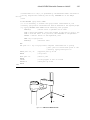
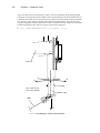
Using a Fixed-Mount Camera
9.3
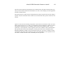
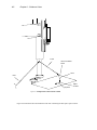
4-Axis SCARA Robot with Camera Mounted on Link #2
. . . . . . . . . . .
138
9.4
5-Axis SCARA Robot with Camera Mounted on Link #2
. . . . . . . . . . .
143
9.5
Guidance Vision Program
. . . . . . . . . . . . . . . . . . . . . . . . . . . . . . .
145
The Sample Program . . . . . . . . . . . . . . . . . . . . . . . . . . . . . . . . . . . .
146
Further Programming Considerations
. . . . . . . . . . . . . . . . . . . . . . .
155
Error Handling . . . . . . . . . . . . . . . . . . . . . . . . . . . . . . . . . . . . . . .
Generalizing the Program . . . . . . . . . . . . . . . . . . . . . . . . . . . . . . . . .
155
155
9.6
10
Advanced Operations
.
.
.
.
.
.
.
.
.
.
.
.
.
.
.
.
.
.
.
.
.
.
.
.
.
.
.
.
.
.
.
.
.
.
.
.
.
.
.
.
.
.
.
.
.
.
.
.
.
.
.
.
.
.
.
.
.
.
.
.
.
.
.
.
.
.
.
.
.
.
.
.
.
.
.
.
.
.
.
.
.
.
.
.
.
.
.
.
.
.
.
.
.
.
.
.
.
.
.
.
. . . . . . . . . . . . . . . . . . . . . . . .
134
157
158
.
.
.
.
.
.
158
159
159
160
160
162
. . . . . . . . . . . . . . . . . . . . . .
162
Blob-Relative Inspection . . . . . . . . . . . . . . . . . . . . . . . . . . . . . . . . .
Prototype-Relative Inspection . . . . . . . . . . . . . . . . . . . . . . . . . . . . . .
162
164
10.2 Performing Frame-Relative Inspections
.
.
.
.
.
.
.
.
.
.
.
.
.
.
.
.
.
.
.
.
.
.
.
.
Setting Vision Switches .
Viewing Switch Settings
Setting Vision Parameters
Viewing Parameters . . .
List of Switches . . . . .
List of Parameters . . . .
.
.
.
.
.
.
.
.
.
.
.
.
.
.
.
.
.
.
.
.
.
.
.
.
.
.
.
.
.
.
.
.
.
.
.
.
.
.
.
.
.
.
.
.
.
.
.
.
.
.
.
.
.
.
.
.
.
.
.
.
.
.
.
.
.
.
.
.
.
.
.
.
.
.
.
.
.
.
.
.
.
.
.
.
165
. . . . . . . . . . . . . . . . . . . .
166
. . . . . . . . . . . . . . . . . . . . . . . . . . . . . . . .
167
10.4 Using a Vision-Guided Tracking Conveyor
Switches and Parameters
.
.
.
.
.
.
. . . . . . . . . . . . . . . .
10.3 Frame-Relative Inspections Using VDEF.TRANS
viii
.
.
.
.
. . . . . . . . . . . . . . . . . . . . . . . . . . . . . . . . . . .
What is “High Speed?” . . . . . . . . . . . . . .
Using the Two Frame Store Areas . . . . . . . .
Using VPICTURE With Different Frame Stores
Using VDISPLAY With Different Frame Stores
Sample Code for a High-Speed Inspection . . .
The High-Speed Trigger . . . . . . . . . . . . . .
B
.
.
.
.
. . . . . . . . . . . . . . . . . . . . . . . . . . . .
10.1 Performing High-Speed Inspections
A
.
.
.
.
.
.
.
.
.
.
167
167
167
167
168
171
. . . . . . . . . . . . . . . . . . . . . . . . . . . . . . . . . . .
175
Viewing VFEATURE( ) Values . . . . . . . . . . . . . . . . . . . . . . . . . . . . .
Establishing VFEATURE( ) Values . . . . . . . . . . . . . . . . . . . . . . . . . . .
175
175
VFEATURE( ) Values
.
.
.
.
.
.
.
.
.
.
.
.
.
.
.
.
.
.
.
.
.
.
.
.
.
.
.
.
.
.
.
.
.
.
.
.
.
.
.
.
.
.
.
.
.
.
.
.
.
.
.
.
.
.
.
.
.
.
.
.
.
.
.
.
.
.
.
.
.
.
.
.
.
.
.
.
.
.
.
.
.
.
.
.
.
.
.
.
.
.
.
.
.
.
.
.
.
.
.
.
.
.
.
.
.
.
.
.
.
.
.
.
.
.
.
.
.
.
.
.
.
.
.
.
.
.
.
.
.
.
.
.
.
.
.
.
.
.
.
.
.
.
.
.
.
.
.
.
.
.
.
.
.
.
.
.
.
.
.
.
.
.
.
.
.
.
.
.
.
.
.
.
.
.
.
.
.
.
.
.
.
.
.
.
.
.
.
.
.
.
.
.
Table of Contents
C
D
Lens Selection
. . . . . . . . . . . . . . . . . . . . . . . . . . . . . . . . . . . . . . . .
179
Formula for Focal Length . . . . . . . . . . . . . . . . . . . . . . . . . . . . . . . .
Formula for Resolution . . . . . . . . . . . . . . . . . . . . . . . . . . . . . . . . . .
179
181
Lighting Considerations
. . . . . . . . . . . . . . . . . . . . . . . . . . . . . . . . .
183
. . . . . . . . . . . . . . . . . . . . . . . . . . . . . . . . . . . .
183
. . . . . . . . . . . . . . . . . . . . . . . . . . . . . . . . . . .
183
.
.
.
.
.
.
.
.
.
.
183
184
184
184
184
. . . . . . . . . . . . . . . . . . . . . . . . . . . . .
185
Polarizing Filters . . . . . . . . . . . . . . . . . . . . . . . . . . . . . . . . . . . . . .
Color Filters . . . . . . . . . . . . . . . . . . . . . . . . . . . . . . . . . . . . . . . .
185
185
D.1
Types of Lighting
D.2
Lighting Strategies
Diffuse .
Back . . .
Directional
Structured
Strobe . .
D.3
E
F
.
.
.
.
.
.
.
.
.
.
.
.
.
.
.
.
.
.
.
.
.
.
.
.
.
.
.
.
.
.
.
.
.
.
.
.
.
.
.
.
Filtering and Special Effects
.
.
.
.
.
.
.
.
.
.
.
.
.
.
.
.
.
.
.
.
.
.
.
.
.
.
.
.
.
.
.
.
.
.
.
.
.
.
.
.
.
.
.
.
.
.
.
.
.
.
.
.
.
.
.
.
.
.
.
.
.
.
.
.
.
.
.
.
.
.
.
.
.
.
.
.
.
.
.
.
.
.
.
.
.
.
.
.
.
.
.
.
.
.
.
.
.
.
.
.
.
.
.
.
.
.
.
.
.
.
.
.
.
.
.
.
.
.
.
.
.
.
.
.
.
.
.
.
.
.
.
.
.
.
.
. . . . . . . . . . . . . . . . . . . . . . . . . . . . . .
The DEVICE Instruction With Vision
187
191
. . . . . . . . . . . . . . . . . . . . . . .
191
. . . . . . . . . . . . . . . . . . . . . . . . . . . . . . . . . . . . . . . . . .
193
Third-Party Suppliers
. . . . . . . . . . . . . . . . . . . . . . . . . . . . . . . . . .
G.1
Third-Party Suppliers (U.S.)
G.2
Third-party Suppliers (Europe)
G.3
Third-Party Suppliers (Asia-Pacific)
Index
.
.
.
.
.
. . . . . . . . . . . . . . . . . . . . . . . . . . . . . . . . . . .
Using DEVICE With Vision
Examples
IX
.
.
.
.
.
Vision Window Menu
F.1
G
. . .
. . .
. .
. . .
. . .
199
. . . . . . . . . . . . . . . . . . . . . . . . . . . . .
199
. . . . . . . . . . . . . . . . . . . . . . . . . . .
204
. . . . . . . . . . . . . . . . . . . . . . . .
208
. . . . . . . . . . . . . . . . . . . . . . . . . . . . . . . . . . . . . . . . . . . . . . .
211
ix
AdeptVision VME User’s Guide
LOF
List of Figures
. . .
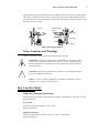
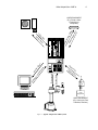
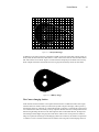
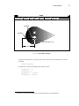
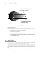
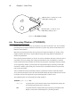
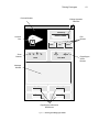
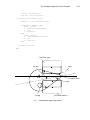
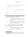
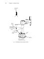
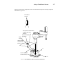
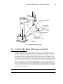
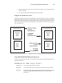
Typical AdeptVision VME System .
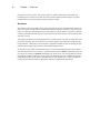
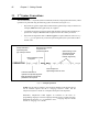
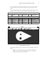
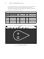
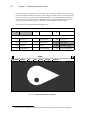
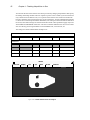
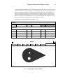
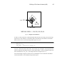
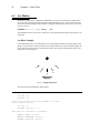
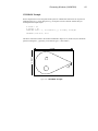
Sample Object . . . . . . . . . .
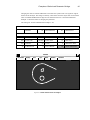
A Grayscale Image . . . . . . . .
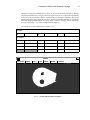
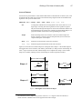
A Binary Image . . . . . . . . .
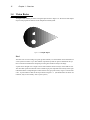
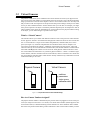
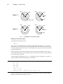
Resolution Factors . . . . . . . .
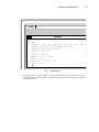
Initial Screen . . . . . . . . . .
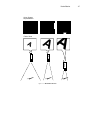
Sample Operation . . . . . . . .
Figure 4-4
.
.
.
.
.
.
.
.
Physical/Virtual Camera Relationship
.
VPICTURE Options . . . . . . . .
.
.
Display Mode Options . . . . . . .
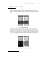
Sample Vision Matrix . . . . . . .
.
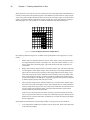
Binary Representation of Sample Matrix .
Figure 4-5
Grayscale Representation of Sample Matrix
Figure 4-6
Sample Object
Impact and Trapping Hazards
Figure 1-1
Figure 1-2
Figure 1-3
Figure 1-4
Figure 1-5
Figure 2-1
Figure 3-1
Figure 3-2
Figure 4-1
Figure 4-2
Figure 4-3
Figure 4-13
. . . . . . . . . .
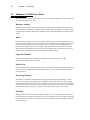
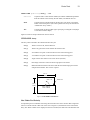
Switch and Parameter Example 1 .
Switch and Parameter Example 2 .
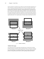
Switch and Parameter Example 3 .
Switch and Parameter Example 4 .
Switch and Parameter Example 5 .
Switch and Parameter Example 6 .
Switch and Parameter Example 7 .
Figure 6-1
Rectangular Area of Interest Shapes
Figure 6-2
Arc Shaped Area of Interest Shapes
Figure 6-3
Sample Area-of-Interest
Figure 4-7
Figure 4-8
Figure 4-9
Figure 4-10
Figure 4-11
Figure 4-12
Figure 6-4
Figure 6-5
Figure 6-6
Figure 6-7
Figure 6-8
Figure 6-9
Figure 6-10
x
. . .
Sample Image Buffer Regions .
Linear Ruler Example . . . .
Sample Gauge Face . . . . .
Arc Ruler Example . . . . . .
Ruler Types . . . . . . . . .
Line Finder Search Area . . .
Finder Tool Polarity . . . . .
.
.
.
.
.
.
.
.
.
.
.
.
.
.
.
.
.
.
.
.
.
.
.
.
.
.
.
.
.
.
.
.
.
.
.
.
.
.
.
.
.
.
.
.
.
.
.
.
.
.
.
.
.
.
.
.
.
.
.
.
.
.
.
.
.
.
.
.
.
.
.
.
.
.
.
.
.
.
.
.
.
.
.
.
.
.
.
.
.
.
.
.
.
.
.
.
.
.
.
.
.
.
.
.
.
.
.
.
.
.
.
.
.
.
.
.
.
.
.
.
.
.
.
.
.
.
.
.
.
.
.
.
.
.
.
.
.
.
.
.
.
.
.
.
.
.
.
.
.
.
.
.
.
.
.
.
.
.
.
.
.
.
.
.
.
.
.
.
.
.
.
.
.
.
.
.
.
.
.
.
.
.
.
.
.
.
.
.
.
.
.
.
.
.
.
.
.
.
.
.
.
.
.
.
.
.
.
.
.
.
.
.
.
.
.
.
.
.
.
.
.
.
.
.
.
.
.
.
.
.
.
.
.
.
.
.
.
.
.
.
.
.
.
.
.
.
.
.
.
.
.
.
.
.
.
.
.
.
.
.
.
.
.
.
.
.
.
.
.
.
.
.
.
.
.
.
.
.
.
.
.
.
.
.
.
.
.
.
.
.
.
.
.
.
.
.
.
.
.
.
.
.
.
.
.
.
.
.
.
.
.
.
.
.
.
.
.
.
.
.
.
.
.
.
.
.
.
.
.
.
.
.
.
.
.
.
.
.
.
.
.
.
.
.
.
.
.
.
.
.
.
.
.
.
.
.
.
.
.
.
.
.
.
.
.
.
.
.
.
.
.
.
.
.
.
.
.
.
.
.
.
.
.
.
.
.
.
.
.
.
.
.
.
.
.
.
.
.
.
.
.
.
.
.
.
.
.
.
.
.
.
.
.
.
.
.
.
.
.
.
.
.
.
.
.
.
.
.
.
.
.
.
.
.
.
.
.
.
.
.
.
.
.
.
.
.
.
.
.
.
.
.
.
.
.
.
.
.
.
.
.
.
.
.
.
.
.
.
.
.
.
.
.
.
.
.
.
.
.
.
.
.
.
.
.
.
.
.
.
.
.
.
.
.
.
.
.
.
.
.
.
.
.
.
.
.
.
.
.
.
.
.
.
.
.
.
.
.
.
.
.
.
.
.
.
.
.
.
.
.
.
.
.
.
.
.
.
.
.
.
.
.
.
.
.
.
.
.
.
.
.
.
.
.
.
.
.
.
.
.
.
.
.
.
.
.
.
.
.
.
. .
. .
.
.
.
.
.
.
.
.
.
.
.
.
.
.
.
.
.
.
.
.
.
.
.
.
.
.
.
.
.
.
5
9
12
13
13
15
23
26
27
36
38
39
39
40
46
47
48
49
50
51
52
53
67
68
69
70
73
74
76
78
79
80
Table of Contents
Figure 9-1
.
.
.
.
.
Executing the VWINDOW Instruction
.
.
Executing a VFIND.LINE Instruction
Executing a VFIND.ARC Instruction .
.
Calculating the Object Tail Location .
.
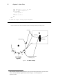
Fixed-Mount Camera (Vision Location) .
Figure 9-2
Fixed-Mount Camera Vision Transformation
Figure 9-3
. . . . . . . .
Calculating the “Link2” Transformation .
Components of the Vision Location . . .
Final Part Acquire Location . . . . . . .
Five-Axis Vision Transformation . . . .
Example Program Setup . . . . . . . .
Pin- Pong Frame Grabbing . . . . . . .
Blob Relative Inspection . . . . . . . .
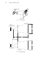
Camera Imaging . . . . . . . . . . . .
Camera Scale Factor . . . . . . . . . .
Figure 6-11
Figure 6-12
Figure 7-1
Figure 7-2
Figure 8-1
Figure 8-2
Figure 8-3
Figure 8-4
Figure 8-5
Figure 9-4
Figure 9-5
Figure 9-6
Figure 9-7
Figure 9-8
Figure 10-1
Figure 10-2
Figure C-1
Figure C-2
. . . . . .
VWINDOW Example . . . . .
Prototype Editing Operations . .
Font Similarity Matrix . . . . .
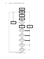
Application Flow Chart . . . . .
Line Finder Example
Link2 Coordinate Frame
.
.
.
.
.
.
.
.
.
.
.
.
.
.
.
.
.
.
.
.
.
.
.
.
.
.
.
.
.
.
.
.
.
.
.
.
.
.
.
.
.
.
.
.
.
.
.
.
.
.
.
.
.
.
.
.
.
.
.
.
.
.
.
.
.
.
.
.
.
.
.
.
.
.
.
.
.
.
.
.
.
.
.
.
.
.
.
.
.
.
.
.
.
.
.
.
.
.
.
.
.
.
.
.
.
.
.
.
.
.
.
.
.
.
.
.
.
.
.
.
.
.
.
.
.
.
.
.
.
.
.
.
.
.
.
.
.
.
.
.
.
.
.
.
.
.
.
.
.
.
.
.
.
.
.
.
.
.
.
.
.
.
.
.
.
.
.
.
.
.
.
.
.
.
.
.
.
.
.
.
.
.
.
.
.
.
.
.
.
.
.
.
.
.
.
.
.
.
.
.
.
.
.
.
.
.
.
.
.
.
.
.
.
.
.
.
.
.
.
.
.
.
.
.
.
.
.
.
.
.
.
.
.
.
.
.
.
.
.
.
.
.
.
.
.
.
.
.
.
.
.
.
.
.
.
.
.
.
.
.
.
.
.
.
.
.
.
.
.
.
.
.
.
.
.
.
.
.
.
.
.
.
.
.
.
.
.
.
.
.
.
.
.
.
.
.
.
.
.
.
.
.
.
.
.
.
.
.
.
.
.
.
.
.
.
.
.
.
.
.
.
.
.
.
.
.
.
.
.
.
.
.
.
.
.
.
.
.
.
.
.
.
.
.
.
.
.
.
.
.
.
.
.
.
82
83
90
98
110
114
117
118
129
136
137
139
140
142
143
144
145
159
164
180
180
xi
AdeptVision VME User’s Guide
List of Tables
LOT
Table 4-1
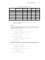
Image-Acquisition Switches . . . . . . . . . . . . . . . . . . . . . . . . . . . . . . . . . . . . . . . . . . . . . . . . . . . . . . . . . . . . . . . 43
Table 4-2
Image-Acquisition Parameters . . . . . . . . . . . . . . . . . . . . . . . . . . . . . . . . . . . . . . . . . . . . . . . . . . . . . . . . . . . . 45
Table 5-1
Boundary Analysis Switches . . . . . . . . . . . . . . . . . . . . . . . . . . . . . . . . . . . . . . . . . . . . . . . . . . . . . . . . . . . . . . 56
Table 5-2
Boundary Analysis Parameter . . . . . . . . . . . . . . . . . . . . . . . . . . . . . . . . . . . . . . . . . . . . . . . . . . . . . . . . . . . . . 57
Table 5-3
VFEATURE Values and Interpretation . . . . . . . . . . . . . . . . . . . . . . . . . . . . . . . . . . . . . . . . . . . . . . . . . . . 60
Table 7-1
Prototype Model Switches . . . . . . . . . . . . . . . . . . . . . . . . . . . . . . . . . . . . . . . . . . . . . . . . . . . . . . . . . . . . . . . 102
Table 7-2
Prototype Model Parameters . . . . . . . . . . . . . . . . . . . . . . . . . . . . . . . . . . . . . . . . . . . . . . . . . . . . . . . . . . . . . 103
Table A-1
Vision Switches . . . . . . . . . . . . . . . . . . . . . . . . . . . . . . . . . . . . . . . . . . . . . . . . . . . . . . . . . . . . . . . . . . . . . . . . . . 168
Table A-2
Vision Parameters . . . . . . . . . . . . . . . . . . . . . . . . . . . . . . . . . . . . . . . . . . . . . . . . . . . . . . . . . . . . . . . . . . . . . . . . 171
Table B-1
VFEATURE( ) Values and Interpretation . . . . . . . . . . . . . . . . . . . . . . . . . . . . . . . . . . . . . . . . . . . . . . 176
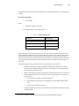
Table C-1
Camera Scale Factors . . . . . . . . . . . . . . . . . . . . . . . . . . . . . . . . . . . . . . . . . . . . . . . . . . . . . . . . . . . . . . . . . . . . 181
Table D-1
Types of Lighting . . . . . . . . . . . . . . . . . . . . . . . . . . . . . . . . . . . . . . . . . . . . . . . . . . . . . . . . . . . . . . . . . . . . . . . . 183
Table F-1
DEVICE Input/Output Format . . . . . . . . . . . . . . . . . . . . . . . . . . . . . . . . . . . . . . . . . . . . . . . . . . . . . . . . . . 192
Table F-2
Vision Memory Allocation . . . . . . . . . . . . . . . . . . . . . . . . . . . . . . . . . . . . . . . . . . . . . . . . . . . . . . . . . . . . . . 192
Table G-1
Fiber Optic Lighting Suppliers . . . . . . . . . . . . . . . . . . . . . . . . . . . . . . . . . . . . . . . . . . . . . . . . . . . . . . . . . . 199
Table G-2
Lighting Suppliers . . . . . . . . . . . . . . . . . . . . . . . . . . . . . . . . . . . . . . . . . . . . . . . . . . . . . . . . . . . . . . . . . . . . . . . . 200
Table G-3
Camera Equipment Suppliers . . . . . . . . . . . . . . . . . . . . . . . . . . . . . . . . . . . . . . . . . . . . . . . . . . . . . . . . . . . . 201
Table G-4
Frame Splitter Suppliers . . . . . . . . . . . . . . . . . . . . . . . . . . . . . . . . . . . . . . . . . . . . . . . . . . . . . . . . . . . . . . . . . 201
Table G-5
Camera Suppliers . . . . . . . . . . . . . . . . . . . . . . . . . . . . . . . . . . . . . . . . . . . . . . . . . . . . . . . . . . . . . . . . . . . . . . . . . 201
Table G-6
Filter and Optics Suppliers . . . . . . . . . . . . . . . . . . . . . . . . . . . . . . . . . . . . . . . . . . . . . . . . . . . . . . . . . . . . . . 202
Table G-7
Lens Suppliers . . . . . . . . . . . . . . . . . . . . . . . . . . . . . . . . . . . . . . . . . . . . . . . . . . . . . . . . . . . . . . . . . . . . . . . . . . . . 202
Table G-8
Mounting Hardware Suppliers . . . . . . . . . . . . . . . . . . . . . . . . . . . . . . . . . . . . . . . . . . . . . . . . . . . . . . . . . . . 204
Table G-9
Lighting Suppliers . . . . . . . . . . . . . . . . . . . . . . . . . . . . . . . . . . . . . . . . . . . . . . . . . . . . . . . . . . . . . . . . . . . . . . . . 204
Table G-10
Lens Suppliers . . . . . . . . . . . . . . . . . . . . . . . . . . . . . . . . . . . . . . . . . . . . . . . . . . . . . . . . . . . . . . . . . . . . . . . . . . . . 205
Table G-11
Filter and Optics Suppliers . . . . . . . . . . . . . . . . . . . . . . . . . . . . . . . . . . . . . . . . . . . . . . . . . . . . . . . . . . . . . . 205
Table G-12
Lighting, Filter, and Optics Suppliers . . . . . . . . . . . . . . . . . . . . . . . . . . . . . . . . . . . . . . . . . . . . . . . . . . . 208
xii
Introduction
. . . . . .
How to Use This Manual .
Organization . . . . .
Before You Begin
. .
Related Manuals . . .
Safety . . . . . . . .
Compatibility
.
.
.
.
.
.
.
.
.
.
.
.
.
.
.
.
.
.
.
.
.
.
.
.
.
.
.
.
.
.
.
.
.
.
.
.
.
.
.
.
.
.
.
.
.
.
.
.
.
.
.
.
.
.
.
.
.
.
.
.
.
.
.
.
.
.
.
.
.
.
.
.
Reading and Training for Users and Operators
System Safeguards . . . . . . . . . . .
. . . . .
. . . . . . . . .
How Can I Get Help?
Within the Continental United States .
Service Calls . . . . . . . . .
Application Questions . . . . .
Training Information . . . . .
Within Europe . . . . . . . . . . .
.
.
.
.
.
.
.
Outside Continental United States or Europe .
Adept Bulletin Board Service (BBS)
. . . .
Notes, Cautions, and Warnings
.
.
.
.
.
.
.
.
.
.
.
.
.
.
.
.
.
.
.
.
.
.
.
.
.
.
.
.
.
.
.
.
.
.
.
.
.
.
.
.
.
.
.
.
.
.
.
.
.
.
.
.
.
.
.
.
.
.
.
.
.
.
.
.
.
.
.
.
.
.
.
.
.
.
.
.
.
.
.
.
.
.
.
.
.
.
.
.
.
.
.
.
.
.
.
.
.
.
.
.
.
.
.
.
.
.
.
.
.
.
.
.
.
.
.
.
.
.
.
.
.
.
.
.
.
.
.
.
.
.
.
.
.
.
.
.
.
.
.
.
.
.
.
.
.
.
.
.
.
.
.
.
.
.
.
.
.
.
.
.
.
.
.
.
.
.
.
.
.
.
.
.
.
.
.
.
.
.
.
.
.
.
.
.
.
.
.
.
.
.
.
.
.
.
.
.
.
.
.
.
.
.
.
.
.
.
.
.
.
.
.
.
.
.
.
.
.
.
.
.
.
.
.
.
.
.
.
.
.
.
.
.
.
.
.
.
.
.
.
.
.
.
.
.
.
.
.
.
.
.
.
.
.
.
.
.
.
.
.
.
.
.
.
.
.
.
.
.
.
.
.
.
.
.
.
.
.
.
.
.
.
.
.
.
.
.
.
.
.
.
.
.
.
.
.
.
.
.
.
.
.
.
.
2
2
2
3
3
4
4
4
5
5
5
6
6
6
6
6
6
2
Introduction
Compatibility
This manual is for use with V+ systems equipped with the AdeptVision software and hardware
options. The system version must be 11.0 or later.
This manual is intended primarily for vision application programmers. If your system includes the
optional VisionWare or MotionWare with vision software, you do not need to read this manual.
However, many principles of machine vision and AdeptVision VME processing are covered in
greater detail here than in the VisionWare or MotionWare user’s guides, so a general review of this
manual may be useful.
How to Use This Manual
Organization
Material in this manual is presented in a step-by-step fashion. Each chapter expands on and relies
on information in the preceding chapters. If you are new to machine vision systems, this manual
will take you from the conceptual basis for machine vision to advanced programming techniques in
computer vision applications. Here is what you will find in each of the chapters:
Chapter 1
presents an overview of machine vision principles and introduces vocabulary and
concepts you will need when reading the other chapters.
Chapter 2
shows you how to physically set up the AdeptVision VME system hardware.
Chapter 3
shows you how to perform all the initialization tasks necessary to get your system
ready to start developing vision applications.
Chapter 4
introduces vision processing. It describes how to acquire and process an image.
You will learn to fine-tune the images you produce so your vision applications
run as efficiently and predictably as possible.
Chapter 5
describes the first vision processing strategy, boundary analysis. You will learn
where vision data is stored and how you can influence the data the vision system
gathers.
Chapter 6
describes the second vision processing strategy, vision tools. You will learn to use
rulers, finders, and inspection windows.
Chapter 7
describes the vision modeling process, including prototype recognition, optical
character recognition (OCR), and correlation templates.
Chapter 8
presents a sample program. You will learn how to combine the knowledge gained
in the previous chapters to program an inspection vision application.
Chapter 9
covers using the vision system to guide a motion device. You will learn how to
set up and calibrate cameras that will locate, acquire, and place parts. If you do
not have a motion device, you can skip this chapter.
How to Use This Manual
Chapter 10
3
discusses advanced topics in vision processing. High speed inspections, part-relative inspections, and conveyor operations are covered.
Before You Begin
AdeptVision VME is an extension of the V+ operating system and language. In order to use the
AdeptVision VME extension you must be familiar with the basic V + operating system and language. In particular, this manual assumes that you:
•
Are familiar with the Adept A-series graphical user interface.
•
Can use the SEE program editor to create and edit programs.
•
Are familiar with V+ programming, including control structures, data types, and subroutine principles.
The V+ operating system and graphical user interface are covered in the V+ Operating System
User’s Guide and the V+ Operating System Reference Guide. The V+ language is covered in the V+
Language User’s Guide and the V+ Language Reference Guide.
Related Manuals
There are several manuals you should have handy as you use this manual. They are:
The Release Notes for V+ 11.0, which contains late-breaking changes not in the manuals, a Summary of Changes, and a section on Upgrading Pre-11.0 code.
The V+ Operating System User’s Guide, which covers operating system tasks such as
copying files, executing programs, and using the graphical interface.
The V+ Operating System Reference Guide, which details the operating system commands (known as monitor commands).
The V+ Language User’s Guide and the V+ Language Reference Guide, which contain a
complete description of the commands, instructions, functions, and other features available in the V+ language. These manuals are essential for advanced applications programming.
The AdeptVision Reference Guide, which contains a complete description of the vision
enhancements to the V+ language. This manual is a companion guide to the AdeptVision
VME User’s Guide.
The Instructions for Adept Utility Programs, many of which are referenced in this manual.
The Advanced Camera Calibration Program User’s Guide, which details the camera
calibration procedures.
The Adept MV Controller User’s Guide. This manual contains information on installing, maintaining, and configuring the physical controller hardware.
The user’s guide for your robot or motion device (if your system includes a motion
device). This manual contains information on installing, maintaining, and calibrating the
motion device.
4
Introduction
The manuals for any options you have purchased with the system (such as VisionWare),
or purchased separately to use with the system.
Safety
Reading and Training for Users and Operators
Adept systems may contain computer-controlled robot mechanisms that are capable of moving at
high speeds and exerting considerable force. Like all robot systems and most industrial equipment,
they must be treated with respect by the user and the operator.
This manual should be read by all personnel who operate or maintain Adept robot systems, or who
work within or near the robot workcell.
We also recommend you read the American National Standard for Industrial Robot Systems Safety Requirements, published by the Robotic Industries Association (RIA), in conjunction with
the American National Standards Institute. The publication, ANSI/RIA R15.06 - 1986, contains
guidelines for robot system installation, safeguarding, maintenance, testing, start-up, and operator
training. The document is available from the American National Standards Institute, #13THF, 11
West 42nd Street, New York, NY 10036-8002.
NOTE: This manual follows RIA definitions of “user” as the responsible person
or company and “operator” as a person who starts, stops, or monitors robot
operation.
This manual assumes that the user has attended an Adept training course and has a basic working
knowledge of the robot system. The user should provide the necessary additional training for all
personnel who will be working with the system.
System Safeguards
Safeguards should be an integral part of robot workcell design, installation, operator training, and
operating procedures.
Adept robot systems have various communication features to aid in constructing system safeguards.
These include remote emergency stop circuitry, and digital input and output lines. These features
are described in the controller user’s guide.
Because Adept robots are computer-controlled, the program that is currently running the robot may
cause it to move unexpectedly. When the amber HIGH POWER and the blue “Program Running”
lights on the optional Adept front panel are lit, the robot might move. When these lights are lit, no
one should enter the workcell, because they cannot predict when or where the robot might move.
The LAMP TEST button allows this light to be periodically checked (see the controller user’s guide).
In addition, these systems can be programmed to control equipment or devices other than the robot.
As with the robot, the program controlling these devices may cause them to operate unexpectedly.
It is critical that safeguards be in place to prevent personnel from entering the workcell when a program is running. The blue PROGRAM RUNNING light on the front of the optional front panel indicates the program is running. The LAMP TEST button allows this light to be periodically checked.
WARNING: Entering the robot workcell when either the HIGH POWER or the
PROGRAM RUNNING light is on can result in severe injury.
Notes, Cautions, and Warnings
5
Adept Technology highly recommends the use of additional safety features such as light curtains,
safety gates, or safety floor mats to prevent entry to the workcell while ARM POWER is enabled.
These devices may be connected using the system’s remote emergency stop circuitry. See the Adept
MV Controller User’s Guide.
Impact!
Trapping (Pinch)
Points
Impact and Trapping Hazards
Notes, Cautions, and Warnings
There are two levels of special notation used in this manual. They are:
WARNING: If the actions indicated in a “WARNING” are not complied with,
injury or major equipment damage could result. A warning statement typically
describes the hazard, its possible effect, and the measures that must be taken to
reduce the hazard.
!
CAUTION: If the action specified in the “CAUTION” is not complied with, damage to your equipment could result.
NOTE: A “NOTE” provides supplementary information, emphasizes a point or
procedure, or gives a tip for easier operation.
How Can I Get Help?
Within the Continental United States
Adept Technology maintains a Customer Service Center at its headquarters in San Jose, CA. The
phone numbers are:
Service Calls
(800) 232-3378 (24 hours per day, 7 days a week)
(408) 433-9462 FAX
Application Questions
(800) 232-3378 (Monday to Friday, 8:00 a.m. to 5:00 p.m., Pacific time)
(408) 434-6248 FAX
6
Introduction
Training Information
For information regarding Adept Training Courses in the USA, please call (408) 434-5024.
Within Europe
For European customers outside of France, Adept Technology maintains a Customer Service Center in Dortmund, Germany. The phone numbers are:
(49) 231 / 75 89 40 from within Europe (Monday to Friday, 8:00 a.m. to 5:00 p.m., CET)
(49) 231/75 89 450 FAX
France
For customers in France, Adept Technology maintains a Customer Service Center in Paris, France.
The phone numbers are:
(33) 1 69 19 16 16 (Monday to Friday, 8:30 a.m. to 5:30 p.m., CET)
(33) 1 69 32 04 62 FAX
Outside Continental United States or Europe
For service calls, application questions, and training information, call the Adept customer service
center in San Jose, California USA:
(408) 434-5000
(408) 433-9462 FAX (service requests)
(408) 434-6248 FAX (application questions)
NOTE: When calling with a controller related question, please have the serial
number of the controller. If your system includes an Adept robot, also have the
serial number of the robot. The serial numbers can be determined by using the ID
command (see the V+ Operating System User’s Guide) .
Adept Bulletin Board Service (BBS)
Adept maintains a bulletin board service for Adept customers. Adept posts application hints and
utilities to this bulletin board and users may post their own hints and application notes. There is no
charge for access to the bulletin board. The BBS number is (203) 264-5590. The first time you call
you will be able to set up an account right from the BBS. If you have any questions, call (800) 2323378 and ask about the BBS.
1
Overview
. . . . . . . . . . . . . .
What AdeptVision VME Is . . . . . . .
Physical Equipment . . . . . . . . .
Controller and Vision Processor
. . .
Robot or Motion Device . . . . . . .
Graphics Terminal
. . . . . . . . .
User Equipment
. . . . . . . . . .
. . . . .
What AdeptVision VME Does
. . . . . . . . . . . . .
Vision Basics
Pixel
. . . . . . . . . . . . . . .
The Camera Imaging Surface
. . . .
Resolution . . . . . . . . . . . . .
. . . . . .
Summary of Software Tools
Boundary Analysis . . . . . . . . .
Rulers . . . . . . . . . . . . . . .
Inspection Windows
. . . . . . . .
Finder Tools . . . . . . . . . . . .
Processing Windows . . . . . . . .
Modeling
. . . . . . . . . . . . .
Overview of Guidance Vision . . . . . .
Frames
. . . . . . . . . . . . . .
Introduction
.
.
.
.
.
.
.
.
.
.
.
.
.
.
.
.
.
.
.
.
.
.
.
.
.
.
.
.
.
.
.
.
.
.
.
.
.
.
.
.
.
.
.
.
.
.
.
.
.
.
.
.
.
.
.
.
.
.
.
.
.
.
.
.
.
.
.
.
.
.
.
.
.
.
.
.
.
.
.
.
.
.
.
.
.
.
.
.
.
.
.
.
.
.
.
.
.
.
.
.
.
.
.
.
.
Things to Consider When Designing Your Workcell
Consistent Environment
Ease of Maintenance
.
Safety . . . . . . . .
Lighting . . . . . . .
.
.
.
.
.
.
.
.
.
.
.
.
.
.
.
.
.
.
.
.
.
.
.
.
.
.
.
.
.
.
.
.
.
.
.
.
.
.
.
.
.
.
.
.
.
.
.
.
.
.
.
.
.
.
.
.
.
.
.
.
.
.
.
.
.
.
.
.
.
.
.
.
.
.
.
.
.
.
.
.
.
.
.
.
.
.
.
.
.
.
.
.
.
.
.
.
.
.
.
.
.
.
.
.
.
.
.
.
.
.
.
.
.
.
.
.
.
.
.
.
.
.
.
.
.
.
.
.
.
.
.
.
.
.
.
.
.
.
.
.
.
.
.
.
.
.
.
.
.
.
.
.
.
.
.
.
.
.
.
.
.
.
.
.
.
.
.
.
.
.
.
.
.
.
.
.
.
.
.
.
.
.
.
.
.
.
.
.
.
.
.
.
.
.
.
.
.
.
.
.
.
.
.
.
.
.
.
.
.
.
.
.
.
.
.
.
.
.
.
.
.
.
.
.
.
.
.
.
.
.
.
.
.
.
.
.
.
.
.
.
.
.
.
.
.
.
.
.
.
.
.
.
.
.
.
.
.
.
.
.
.
.
.
.
.
.
.
.
.
.
.
.
.
.
.
.
.
.
.
.
.
.
.
.
.
.
.
.
.
.
.
.
.
.
.
.
.
.
.
.
.
.
.
.
.
.
.
.
.
.
.
.
.
.
.
.
.
.
.
.
.
.
.
.
.
.
.
.
.
.
.
.
.
.
.
.
.
.
.
.
.
.
.
.
.
.
.
.
.
.
.
.
.
.
.
.
.
.
.
.
.
.
.
.
.
.
.
.
.
.
.
.
.
.
.
.
.
.
.
.
.
.
.
.
.
.
.
.
.
.
.
.
.
.
.
.
.
.
.
.
.
.
.
.
.
.
.
.
.
.
.
.
. .
. .
. .
.
.
.
.
.
.
.
.
.
.
.
.
.
.
.
.
.
.
.
.
.
.
.
8
8
8
10
10
10
10
11
12
12
13
14
16
16
16
16
16
16
16
17
17
17
17
17
17
18
8
1.1
Chapter 1 - Overview
Introduction
This section presents an overview of machine vision. It gives a brief description of how a vision
system “sees”, and what equipment and software tools you have for extracting information about
what the vision system “sees”.
1.2
What AdeptVision VME Is
Physical Equipment
A basic AdeptVision VME system consists of:
•
A controller equipped with a vision processor board
•
A robot or motion device (optional)
•
One or more cameras
•
The A-series controller option that includes:
High-resolution color monitor
AT-compatible keyboard
Trackball (or other pointing device)
In addition, your system will probably contain special lighting equipment and camera mounting
equipment. This vision system is generally integrated with parts delivery systems and other usersupplied equipment to form a workcell that performs the tasks you have designated for the system.
The major components an AdeptVision VME system may have are described below. Figure 1-1
shows a typical system.
9
USER EQUIPMENT
(E.g. Printer, Other
Controllers or
Computers)
Si
gn
HD/SCSI
OK
1 2 3 4
ON
1 2 3 4 5 6 7 8
ON
al
D
R
I
V
E
RESET
NO CHARGE
CHARGING
R
FULL CHARGE S
4
2
2
/
4
8
5
F
P
/
M
C
P
R
S
2
3
2
/
T
E
R
M
R
S
2
3
2
R
S
2
3
2
V
I
D
E
O
B
U
S
B
U
S
E
N
C
O
D
E
R
A
INTERNAL BATTERY STATUS
V
I
D
E
O
R
S
2
3
2
2
4
V
1
0
0
m
A
E
T
H
E
R
N
E
T
S
C
S
I
ut
Inp
na
M
O
N
I
T
O
R
M
A
C
H
I
N
E
EXT BATTERY OK
I
/
O
ria
ACC VIOL
l /A
VGB
E-STOP
ria
VIS
OK
Se
VMI
l /A
SIO
030
BACK UP ENABLED
Se
e
a
at
na
D
log
e
ag
b
ro
St
BAT
log
Im
Ou
tp
ut
LENS
DC IN
EXT SYNC
VIDEO OUT
What AdeptVision VME Is
S
E
R
V
O
EXTERNAL BATTERY
C
A
M
E
R
A
S
/
S
T
R
O
B
E
S
P
O
I
N
T
E
R
KEYBOARD
pu
t
®
ev
git
REPLACE FUSE WITH
SAME TYPE AND RATING
Di
L
G
Encoder data
Drive signals
oin
/P
rd
oa
yb
Ke
al
git
N
te
M
rD
on
ito
ice
rO
ut
Di
al
Inp
ut
Ou
tpu
t
adept
User
Equipment
USER EQUIPMENT
(Eg. Conveyors, Part
Handlers, Sensors)
Figure 1-1. Typical
AdeptVision VME System
10
Chapter 1 - Overview
Controller and Vision Processor
The controller contains the logic boards, system and vision processor boards, I/O boards, and camera connector. This hardware system provides an environment for Adept’s V+ Operating System
and Language that allows you to direct and monitor vision operations. The hardware/software combination is multitasking and contains everything necessary to control:
•
Four physical cameras per vision system (32 virtual cameras)
•
Strobe lights for two physical cameras (AdeptVision VME provides the connection for a
signal pulse for user-supplied strobe lights)
•
A graphics monitor
•
User-installed serial, digital, and (optionally) analog I/O devices
•
User-supplied equipment such as conveyor belts (systems equipped with motion
devices)
Robot or Motion Device
Adept controllers may control robots or other motion devices. This manual describes vision guidance for the standard Adept robots. The principles described for these robots can be generalized to
any other motion devices your system may be using.
Graphics Terminal
The graphics monitor displays all vision system input and output. The system supports multiple
windows; the monitor can display output from a camera, input from other cell control equipment,
as well as operator input and prompts. The graphics monitor is used along with the keyboard and
trackball to develop vision applications. This equipment can also be set up to function as the operator interface during execution of vision applications.
User Equipment
You can communicate with the controller using serial, digital, and analog I/O. The serial channels
support RS-232, RS422, and RS485 protocols which are generally used for printer output and communication with other controllers or computers.
The digital output channels are used to switch the user-supplied current to external equipment. Signaling a part feeder to place a part in the field-of-view is a sample digital output operation.
Digital input channels tell the controller that an event (such as a part being placed in the field-ofview) has occurred, and that your program should either suspend or continue execution (or take any
other appropriate action).
The optional analog I/O channels allow you to read from, and write to, compatible analog I/O
devices.
See the Adept MV Controller User’s Guide for details on installing digital, serial, and analog I/O
devices. See the V+ Language Reference Guide descriptions of IO, SIG, and SIGNAL() for details on
programming digital I/O. See the descriptions of ATTACH, READ, GETC, WRITE, and DETACH for
details on programming serial I/O. See the descriptions of AIO.IN and AIO.OUT for details on ana-
What AdeptVision VME Does
11
log I/O. See the description of the utility program CONFIG_C in the Instructions for Adept Utility
Programs for details on the configuration of digital, analog, and serial I/O.
1.3
What AdeptVision VME Does
Quite simply, the AdeptVision VME system looks at something and then tells you what it knows
about that thing. The system has software tools that allow you to control how AdeptVision VME
looks at objects and what information it gathers about those objects. AdeptVision VME has three
primary information processing strategies:
•
In the first strategy, boundary analysis, AdeptVision VME looks at the boundaries of
whatever is in the field-of-view and calculates information such as the perimeter, centroid, and area of each bounded region.
•
In the second strategy, vision tools, you place ruler, window, and finder tools in the fieldof-view, and AdeptVision VME returns information based on what it finds with those
tools.
•
In the third strategy, vision model processing, AdeptVision VME compares each
bounded region in the field-of-view with known shapes or models you have placed in
memory, and attempts to identify the region. Prototype recognition, OCR, and image
correlation are the options in this mode of operation.
Each of these processing strategies can be used independently or in conjunction with the
other two.
Inspection vision systems will use the results of the various vision options to make quality, gauging,
and other measurements of objects in the field-of-view.
Guidance vision systems will use vision options to locate and acquire items in the field-of-view.
12
1.4
Chapter 1 - Overview
Vision Basics
Throughout this manual you will be seeing the object shown in Figure 1-2. We will use this sample
object to help explain the features of the AdeptVision VME system.
Figure 1-2.
Sample Object
Pixel
The basic unit of a vision image is a pixel (picture element). It is the smallest unit of information a
vision system can return to you. The number of pixels the system can process determines the system’s resolution and affects the computer processing time needed to analyze an image.
A pixel can be thought of as a single cell in a matrix that the camera overlays on the field-of-view.
The value that is placed in that cell will be a shade of gray that represents the intensity of the light
reflected from the corresponding area in the field-of-view (grayscale vision). Figure 1-3 shows how
a 22 x 16 pixel camera would see the object shown in Figure 1-2. (The dashed lines are shown for
reference; they are not actually “seen” by the system.)
Vision Basics
Figure 1-3.
13
A Grayscale Image
In addition to grayscale processing, AdeptVision VME can process image data in binary mode. In
binary mode, all the cells with a value above a certain value will be seen as white and those below
that value will be seen as black. Figure 1-4 shows how the sample object would be seen in binary
mode. Chapter 4 discusses the features and uses of grayscale and binary modes in more detail.
Figure 1-4.
A Binary Image
The Camera Imaging Surface
Video cameras used for machine vision replace the film used in a traditional camera with a light
sensitive electronic surface. When you instruct the system to acquire an image (“take a picture”),
the imaging surface is “exposed” for a short time and the “exposure” is read into the vision processor. The electronic surface is actually an array of photon detectors that store a charge based on the
amount of light hitting the detector. The more light that hits an individual detector, the larger the
stored charge and the higher the grayscale value that is read into the vision processor. When an
image is acquired, all the charges in the imaging surface are zeroed out, the surface is exposed for
1/10,000 to 1/30 of a second, and the value recorded in each cell (pixel) of the imaging surface is
14
Chapter 1 - Overview
read into the vision processor. The resulting matrix of values is analyzed to locate edges and
bounded regions. Vision tools can then be used to measure distances between edges, recognize
bounded regions, and extract other information about the image.
Resolution
The number of rows and columns in the camera imaging surface, the lens focal length, and the distance of an object from the camera will determine the final resolution of whatever you are viewing.
Figure 1-5 shows the relationship between focal length and viewing distance. In general, optimum
resolution will come when the object of interest fills as much of the field-of-view as possible while
still being in focus.
The image representation of our hypothetical 22 x 16 camera shows very poor resolution due to the
low density of pixels. The size of the arrays in cameras supported by AdeptVision VME typically
ranges from 501 x 485 pixels to 768 x 493 pixels. Appendix C details the steps to selecting the optimum lens focal length, viewing distance, and camera imaging surface.
An important concept that is illustrated by Figure 1-5 is the relationship between a pixel’s dimensions and the physical size of an object. A pixel will always have a relative relationship to the size
of an object. It will have an absolute relationship only when you fix your viewing distance and lens
focal length, and then calibrate the vision system. The calibration process establishes an absolute
relationship between a pixel and the actual dimensions of the field-of-view. “Camera Calibration”
on page 28 discusses the utilities Adept makes available to establish this relationship.
Vision Basics
Vision System
Representation
Field of View
A
A
A
f=75mm
f=25mm
f=75mm
A
A
Figure 1-5.
Resolution Factors
A
15
16
1.5
Chapter 1 - Overview
Summary of Software Tools
This section gives a brief overview of the vision tools provided by AdeptVision VME. These tools
are detailed in Chapters 5, 6, and 7.
Boundary Analysis
Boundary analysis locates objects in the field-of-view and returns information about those objects’
sizes, locations, perimeters, etc. Boundary analysis locates objects by looking for bounded areas (a
contiguous area of light or dark pixels in the binary image). These bounded areas are often called
“blobs”.
Rulers
Rulers are inspection tools you place in the vision image that return information based on the values found in the pixels the ruler crosses. Linear rulers return distances between features of an object
based on intensity changes (edges) in the field-of-view. Arc rulers return the angular distance
between object features. You can set the length, angle, and position of these rulers. Rulers work
with both grayscale and binary images. You can place multiple rulers in the field-of-view, inspect
multiple objects, and examine the relationship between multiple objects.
Inspection Windows
Inspection windows provide a quick way of obtaining basic graylevel, binary, or edge
statistics about specific areas of an image.
Finder Tools
These tools allow you to find points, lines, and arcs in an image. The data returned from finder tools
may provide all the information you need about an object, or it may provide the basis to perform
other inspections.
Processing Windows
In Chapter 5 you will learn the difference between processed and unprocessed images. In many
cases, you can speed up your applications by operating on unprocessed images or by processing
only a limited portion of the field-of-view. Processing windows allow you to process a limited area
of the field-of-view. (In contrast to inspection windows, processing windows do not return any data
about the image: they merely process a portion of an image for use by other vision tools.)
Modeling
Modeling allows you to store models of different objects in vision system memory and then compare these models with objects in the field-of-view. The system will tell you if an object in the fieldof-view matches a model in vision system memory, how close the match is, and where the object is
in the field-of-view.
Overview of Guidance Vision
1.6
17
Overview of Guidance Vision
AdeptVision makes use of the tools just described both to inspect objects and to provide information to the motion device about an object’s location.
Frames
All robot motion is based on frames of reference and location variables. Location variables
uniquely identify a point within a Cartesian space and the orientation of the robot tool at that point.
All robots and motion devices will have a primary reference frame. On Adept SCARA robots the
primary reference frame is centered at the base of the robot with the Z axis pointing straight up, the
X axis going front to back, and the Y axis going left to right.
The V+ language provides several options for creating new frames of reference that are relative to
this primary reference frame. Relative reference frames can also be created with respect to other
relative reference frames. It is these relative reference frames that allow the vision system to guide
robot motions.
Depending on the camera mounting location, different relative reference frames will be used to
relate the camera field of view to the robot work space. Chapters 9 and 10 give the details of creating and using these frames.
1.7
Things to Consider When Designing Your Workcell
While designing your workcell, keep in mind the following considerations:
Consistent Environment
For your results to be consistent and predictable, the environment you operate the vision system in
must be as consistent and predictable as possible.
Avoid major changes in temperature and humidity. Mount the cameras so that a constant distance is
maintained from the camera to the object.
Isolate the cameras as much as possible from sources of vibration.
Ease of Maintenance
Periodic maintenance and repair of your system will be necessary. Design your workcell to allow
access to all the vision system components as well as any other equipment you may have installed.
Safety
If there is any moving equipment, such as part feeders or conveyor belts, design the workcell so that
all normal operations can take place without the operator coming into dangerous contact with the
moving equipment.
18
Chapter 1 - Overview
Lighting
Consistent lighting is critical to accurate, predictable vision operations. Appendix D lists the advantages and disadvantages of various lighting systems. Before you select and install a lighting system,
experiment with different lighting setups and see which one provides you with the most consistent
results. These results should be checked throughout the duration of the shift in which the system
will be operated to see how changes in ambient light affect the system.
Creating an optimum and consistent lighting environment
when you design your workcell will save a great deal
of trouble later!
Installation
. . . . . .
Installing the Controller . . . . .
Attaching Cameras and Strobes . .
Strobe Compatibility
. . .
Setting Up the Hardware
.
.
.
.
.
.
.
.
.
.
.
.
Cameras Supported by AdeptVision VME
Panasonic GP-CD 40 . . . . . .
Panasonic GP-MF 702
. . . . .
Sony XC-77 . . . . . . . . . .
Mounting Cameras . . . . . . . . . .
Setting Up the Software
. . . . . . . . .
.
.
.
.
.
.
.
.
.
.
.
.
.
.
.
.
.
.
.
.
.
.
.
.
.
.
.
.
.
.
.
.
.
.
.
.
.
.
.
.
.
.
.
.
.
.
.
.
.
.
.
.
.
.
.
.
.
.
.
.
.
.
.
.
.
.
.
.
.
.
.
.
.
.
.
.
.
.
.
.
.
.
.
.
.
.
.
.
.
.
.
.
.
.
.
.
.
.
.
.
.
.
.
.
.
.
.
.
.
.
.
.
.
.
.
.
.
.
.
.
.
.
.
.
.
.
.
.
.
.
.
.
.
.
.
.
.
.
.
.
.
.
.
.
.
.
.
.
.
.
.
.
.
.
.
.
.
.
.
.
.
.
.
.
.
.
.
.
.
.
2
.
.
.
.
.
.
.
.
.
.
.
.
.
.
.
.
.
.
.
.
20
20
20
20
21
21
21
21
22
22
20
2.1
Chapter 2 - Installation
Setting Up the Hardware
Your vision system includes the following items:
•
An Adept A-series controller equipped with:
A System Processor Board
Graphics Processor Board
Vision Processor Board (VIS) or Enhanced Vision Interface Board (EVI)
V+ Operating System and Language (Version 11.0 or later) with the Vision option
•
Utility Programs Disk
•
High-resolution color monitor
•
AT compatible keyboard and pointing device
•
One or more cameras
You may be installing the following options:
•
Camera lenses, extension tubes
•
Strobe lights or other area lighting
•
Optical filters
•
Camera mounting hardware
•
Robot or motion device
Installing the Controller
Your controller should be set up and configured before you install the peripheral vision system
equipment. See Adept MV Controller User’s Guide for details on setting up the controller. This
guide also shows where to connect the monitor, keyboard, and pointing device to the controller.
If you are using digital I/O, pay particular attention to the controller user’s guide’s instructions on
installing and configuring digital I/O in your workcell.
Attaching Cameras and Strobes
The Adept MV Controller User’s Guide shows how to connect cameras and strobes and to set any
hardware options required by the various cameras and strobes.
Appendix G lists several manufacturers who supply strobe lighting (and general lighting) that is
compatible with AdeptVision systems.
Strobe Compatibility
Adept’s strobe signal is TTL compatible with a duration of 120 µsec and an output of 80 - 120 mA
(positive going pulse). The stobe signal is normally set “active high”, but can be configured using
the DEVICE instruction (see Appendix F). Strobe lights have a latency between signal detection
and flash. This latency combined with the flash duration should not exceed 100 µsec.
Setting Up the Hardware
21
Cameras Supported by AdeptVision VME
The cameras listed here can be used with AdeptVision VME. Not all features of all cameras are
supported by AdeptVision VME. The following highlights the main features of each camera:
Panasonic GP-CD 40
This low cost, medium-resolution camera has a resolution of 501 x 485 pixels. It can also be used as
an electronically shuttered camera (fixed at 1/1000 sec).
Nonshuttered cameras require about 1/30 of a second to acquire an image. This speed is too slow to
acquire unblurred images of moving parts. Shuttered cameras have shutter speeds of 1/1,000 to 1/
10,000 sec., allowing them to acquire clear images of moving parts without the use of strobe lighting. With shuttered cameras, the strobe signal is used to latch the external encoders of motion
devices simultaneously with image acquisition. Since the timing of a strobe signal used to record
encoder positions is different from the timing for a strobe light, cameras used in shuttered mode
cannot be used with strobe lights.
When you are using a shuttered camera, images must be acquired in field-acquire mode.
Panasonic GP-MF 702
This camera has a resolution of 649 x 491 pixels. This camera can be set up to use the “pixel clock”
output of the vision board. This camera uses an MOS array rather than a CCD array for the imaging
element. MOS arrays shift data from the imaging element to the vision processor differently from
CCD array cameras. Therefore, asynchronous strobe operation will not work.
Sony XC-77
This is an electronically shuttered camera with a resolution of 768 x 493 pixels. See the description
of the Panasonic GP-CD 40 camera for additional details on shuttered cameras. This camera can be
set to operate in standard, nonshuttered mode.
The Sony XC-77 provides both synchronous and asynchronous shuttered capability. When used in
asynchronous mode, the maximum number of images that can be acquired per second is 30 (60 is
the maximum in synchronous mode).
NOTE: When a camera is used in pixel-clocked, asynchronous, or shuttered
mode, the camera must be properly set up to operate in the selected mode. See
the camera instructions for details on setting up the camera for different operating
modes.
The following cameras are also compatible with AdeptVision VME:
•
Hitachi KP-M1
•
Panasonic GP-MF502
•
Panasonic GP-MF552
Contact your Adept salesperson for details on the cameras sold directly by Adept. Contact Adept
Applications for current details on camera compatibility.
22
Chapter 2 - Installation
Mounting Cameras
Mount your cameras rigidly and dampened from vibration. Consistent vision results depend on
cameras that stay a constant distance from the objects being viewed. Cameras that can skew, change
position on their mounts, or lose focus due to vibration or contact will cause problems over the life
of your application.
Appendix G lists several suppliers of camera and lighting mounting hardware.
2.2
Setting Up the Software
Your vision system leaves the Adept factory with the operating system and vision software installed
on a floppy disk. (If your system has a hard drive, the operating system and vision software are also
installed on the hard drive [C:].)
To boot the system and bring up the vision monitor, turn on the monitor, place the system disk in
drive A, and turn on the controller. If the hard disk option is installed, just turn on the monitor and
controller.
After power is turned on, the system will go through a series of self-tests and then load the operating system. When the load procedure is complete, you will see a screen similar to Figure 2-1 showing copyright information and the ID lines. The ID lines contain coded information about the
configuration of your system. See the ID command in the V+ Language Reference Guide for details
on the meaning of these lines.
Setting Up the Software
23
adept
Monitor
Adept V+
Copyright © 1984, 1985, 1986, 1987, 1989, 1990, 1991, 1992, 1
by Adept Technology, Inc. All rights reserved.
X/Y/Z/Theta Robot Control Module
Software: 11.0 81-1C1
Controller: 3302-5 0
Processor 1: 0.0 1-7 4Mb
Robot 1:: 100-0 0 8
AdeptVision: 11.0 500 1 1Mb
16-Jul-93 09:20:32
.
Figure 2-1.
Initial Screen
When your monitor looks like Figure 2-1, you are ready to begin vision operations and to load
vision application programs. See the V+ Operating System User’s Guide for details on installing
application software.
3
Getting Started
. . . . . . . . .
Virtual Cameras . . . . . . . . . . . . .
What Is a Virtual Camera? . . . . . . .
How Are Camera Numbers Assigned?
.
Why Use Virtual Cameras?
. . . . . .
Camera Calibration . . . . . . . . . . .
Camera Calibration Results
. . . . . .
. . . . .
Motion Devices and Calibration
Motion Device Calibration . . . . . . .
Start-up Calibration . . . . . . . . . .
Camera Calibration . . . . . . . . . .
The Vision Transformation
. . . . . .
.
.
.
.
.
.
.
.
.
.
.
.
Fixed Mount Camera Transformation .
.
.
.
.
.
.
.
.
.
.
.
.
.
Robot-Mounted Camera Transformation .
Loading Vision Calibration Data . . . . . . . .
V+ Syntax Conventions
.
.
.
.
.
.
.
.
.
.
.
.
.
.
.
.
.
.
.
.
.
.
.
.
.
.
.
.
.
.
.
.
.
.
.
.
.
.
.
.
.
.
.
.
.
.
.
.
.
.
.
.
.
.
.
.
.
.
.
.
.
.
.
.
.
.
.
.
.
.
.
.
.
.
.
.
.
.
.
.
.
.
.
.
.
.
.
.
.
.
.
.
.
.
.
.
.
.
.
.
.
.
.
.
.
.
.
.
.
.
.
.
.
.
.
.
.
.
.
.
.
.
.
.
.
.
.
.
.
.
.
.
.
.
.
.
.
.
.
.
.
.
.
.
.
.
.
.
.
.
.
.
.
.
.
.
.
.
.
.
.
.
.
.
.
.
.
.
.
.
.
.
.
.
.
.
.
.
.
.
.
.
.
.
.
.
.
.
.
.
.
.
.
.
.
.
.
.
.
.
.
.
.
.
.
.
.
.
.
.
.
.
.
.
.
.
.
.
.
.
.
.
.
.
.
.
.
.
.
.
.
.
.
.
.
.
.
.
.
.
.
.
.
.
.
.
.
.
.
.
.
.
26
27
27
27
28
28
28
30
30
30
30
30
30
31
31
26
3.1
Chapter 3 - Getting Started
V+ Syntax Conventions
This manual details V+ keywords (monitor commands, functions, and program instructions). These
operations are presented using the following syntax conventions (see Figure 3-1):
•
Keywords are typed in capital letters and should be typed exactly as they are shown. For
example, LOAD should be typed exactly as it appears.
•
Arguments are shown in lowercase letters and should be replaced with arguments you
provide. For example, drive should be replaced with a drive letter you choose.
•
Keywords and arguments shown in bold type are required; and those shown in regular type are optional. If you omit an optional argument, the system will assume a
default value.
All caps indicates a
required keyword;
type exactly as shown.
Bold lowercase indicates
a required userspecified argument.
Bold meands this comma
is required.
Optional string of userspecified arguments
(commas required
between arguments).
OPERATION (opt_arg), req_arg, opt_arg1,...,opt_argn
Lowercase indicates an
optional user-specified argument.
Bold parentheses indicate that
parentheses are required.
Comma required if
optional arguments are used.
Figure 3-1. Sample
Operation
NOTE: For the sake of simplicity, the operations detailed in this manual do not
list all available options. See the V+ Language Reference Guide and the
AdeptVision Reference Guide for a complete description of all keywords.
Remember, AdeptVision VME supplies an extension to the basic V+
programming language. The basic language elements such as control structures,
mathematical functions, etc., are detailed in the V+ Language Reference Guide
and the V+ Language User’s Guide.
Virtual Cameras
3.2
27
Virtual Cameras
AdeptVision VME allows you to establish several virtual cameras for each of your physical cameras (as long as the total number of virtual cameras does not exceed 32). One of the most important
things you will learn in the next three chapters is how to control what a camera sees. You may find
that you want to take several pictures of an object with each picture looking at the object in a different way or from a different distance. Virtual cameras allow you to do this. For example, you might
want your first picture of an object to look at the perimeter shape and your second picture to look at
interior features of the object. By establishing two virtual cameras for the physical camera looking
at the object, you can take both types of pictures of the object.
What Is a Virtual Camera?
The controller allows you to attach four different cameras to each vision processor. These cameras
are the “physical” cameras. Associated with each physical camera will be one or more virtual cameras. A virtual camera is a single set of switches and parameters, calibration data, and a vision
queue (see Figure 3-2). Switches and parameters are introduced in the next two chapters. The
vision queue is introduced in Chapter 5. Calibration is discussed in the next section. A physical
camera can have up to 32 virtual cameras associated with it, but the total number of virtual cameras
associated with all physical cameras can not exceed 32. Each physical camera must have at least
one virtual camera associated with it. If you have 4 physical cameras camera 1 could have eight
virtual cameras, camera 2 could have sixteen virtual cameras, camera 3 could have five virtual cameras, and camera 4 could have three virtual cameras. Or they could have any combination of virtual
cameras that add up to 32 or less.
Physical Camera
Virtual Camera
+
Figure 3-2.
switches
parameters
vision queue
calibration data
Physical/Virtual Camera Relationship
How Are Camera Numbers Assigned?
The physical camera number is determined by the port the camera is plugged into on the vision processor (see Adept MV Controller User's Guide). The virtual camera number (and the physical camera associated with it) is determined during camera calibration or when calibration data is loaded.
One of the first questions asked during camera calibration is what virtual camera number you want
28
Chapter 3 - Getting Started
associated with the physical camera you are calibrating. Your answer to this question determines
which virtual camera is being calibrated and which physical camera it will be associated with.
Why Use Virtual Cameras?
Switches and parameters can be set for an individual virtual camera. Calibration data and prototype
groups can also be defined for individual virtual cameras. Virtual cameras allow you to use the
same physical camera to look at the same image using different combinations of calibration, prototypes, switches, and parameters simply by specifying different virtual cameras.
For example, you might be inspecting different areas of an object, each of which requires its own
switch/parameter settings. Or you might be presenting two (or more) different objects to the same
camera for inspection. If these objects are different distances from the camera (but still in focus),
you will need different camera calibration data for each object. Since camera calibration is established for each virtual camera, you could use different virtual cameras calibrated for the different
distances to inspect the objects.
Unless noted, this manual assumes your system has only one camera and that virtual camera 1 has
been assigned to it. So all references to a camera mean virtual and physical camera 1.
3.3
Camera Calibration
Before you can begin executing vision programs, the system should be calibrated so it has some
basic information about the camera and its field-of-view. Two basic pieces of information it needs
are: the ratio of the width of a pixel to a millimeter in the field of view (x scale) and the ratio of the
height of a pixel to a millimeter in the field of view (y scale). For motion device related cameras,
you must also establish the relationship between the camera field-of-view and the motion device.
During camera calibration, you will need to focus the lens and adjust the lens aperture (f-stop).
There are two methods for calibrating your cameras. The first is to use the Adept utility,
“ADV_CAL”. The second is to use the calibration option in the Adept AIM application programs
(VisionWare or MotionWare with vision). Instructions for using “ADV_CAL” come with the option
package. Instructions for using the AIM calibration option are supplied in the VisionWare User’s
Guide.
Camera Calibration Results
Camera calibration establishes the following relationships:
•
The number of camera pixels per millimeter of the field-of-view. To be able to produce
meaningful distance calculations, the system must know how many camera pixels are
needed to “see” a millimeter of distance in the field-of-view.
•
An option perspective distortion correction, a set of transformations that allow the system to account for fields-of-view that are not parallel to the camera imaging element.
•
For motion device related cameras, the camera-to-robot transformation. In order to guide
the robot, the system must know the relationship between the camera position/orientation and the motion device end effector.
Camera Calibration
NOTE: Before you can begin the calibration procedures, the camera must be
installed in its permanent location. Once a camera has been calibrated, changing
camera location or camera lens focus will invalidate the calibration. When you
calibrate the camera, you establish a distance relationship between the camera
and the field-of-view and between the camera and the motion device. If the
distance changes, these relationships will no longer be valid. Changing the
camera lens or lens focus affects the size of the field-of-view and, therefore, the
distance relationship. Once you have calibrated a camera, you cannot alter the
lens focus (lens focus can be set during calibration).
Adept recommends that you tape or clamp your lens focusing ring after you have
focused the camera but before you begin calibration. This will help prevent
inadverdent focusing of the lens after calibration.
29
30
3.4
Chapter 3 - Getting Started
Motion Devices and Calibration
For systems with motion devices, three different types of calibration must be completed before an
AdeptVision VME system can be used. The three types of calibration are:
Motion Device Calibration
This calibration establishes the relationship between the robot’s encoders and the actual space the
robot works in. On Adept robots, this calibration is performed at the factory and will not need to be
repeated unless an encoder is replaced or other major repair is performed. For other motion devices,
this calibration is performed with the AdeptMotion VME utility SPEC.V2.
Start-up Calibration
When a motion device and its controller are first turned on, the device must relate its current location to the motion device calibration data. This procedure is accomplished by entering the commands:
ENABLE POWER
CALIBRATE
See the robot user’s guide or AdeptMotion VME User’s Guide for more details.
Camera Calibration
The relationship between the camera field-of-view and the motion device must be established
before the vision system can be used to locate objects for the motion device. See the User’s Guide
to the Advanced Camera Calibration Program that came with the calibration package for details on
the various calibration configurations.
The Vision Transformation
Guided vision is essentially the process of putting together several pieces of information to create a
transformation. A transformation defines a location a motion device can move to. You must be
familiar with the Adept transformation value before you can program motion device applications.
See the V+ Language User’s Guide and the V+ Language Reference Guide. The next two sections
summarize this transformation for fixe- mount and for robot arm-mounted cameras. Chapter 9 presents detailed information.
Fixed-Mount Camera Transformation
The transformation value to pick up an object using a fixed-mount camera has the following possible elements:
•
The location, in world coordinates, of the origin of the vision reference frame. This location is created by the camera calibration routine and stored in the “to.cam[ ]” array.
•
The offset and rotation of the part relative to the vision reference frame. These values are
calculated using different vision tools (described in Chapters 5 - 7).
•
The offset from the center of the quill flange to the center of the actual gripping location
(“TOOL transformation”). See the description of the TOOL program instruction in the
V+ Language Reference Guide for details.
Loading Vision Calibration Data
31
Robot-Mounted Camera Transformation
The transformation value to pick up an object using an arm-mount camera has the following elements:
•
The offset, in tool coordinates, from the origin of the vision reference frame to a location
on the robot that is fixed relative to the camera (this location varies depending on the
joint the camera is mounted on). This transformation is created by the camera calibration
routine and is stored in the “to.cam[ ]” array.
•
The offset and rotation of the part relative to the vision reference frame. These values are
calculated using different vision tools (described in Chapters 5 - 7).
•
The offset from the center of the quill flange to the center of the actual gripping location
(“TOOL transformation”). See the description of the TOOL program instruction in the
V+ Language Reference Guide for details.
•
The current position of the robot joint the camera was calibrated to. The robot joint that
the camera calibration transformation is based on moves. Therefore, the current position
of the robot joint must be recalculated each time a picture is taken at a new location. This
is a simple calculation that is described in Chapter 9.
The next four chapters will describe the tools and options available to calculate the necessary parts
of a vision transformation.
3.5
Loading Vision Calibration Data
After you have turned off the controller or zeroed system memory, calibration data is no longer
available and will have to be reloaded. There are two ways of loading calibration data to system
memory from a disk file. The first is to use the camera calibration program. The second is to call the
program “loadarea” from your application program. The Advanced Camera Calibration Program
User’s Guide describes using ADV_CAL to load calibration data.
Loading calibration data by calling “loadarea” from an application program is shown in the programming example in Chapter 8 and described in Instructions for Adept Utility Programs.
If you are using VisionWare or MotionWare with vision, the calibration data is automatically
loaded when VisionWare or MotionWare is started.
NOTE: In order for loaded calibration data to be valid, the physical camera
associated with the virtual camera must be in the same location and have the
same lens settings as when it was calibrated. If this is not the case, the system
will still return data, but the data may not be valid.
Teaching AdeptVision to See
. . . . . . . . . . . . .
Physical vs. Virtual Cameras . . . .
The Point of Origin . . . . . . . .
. . .
VPICTURE—Getting an Image
VPICTURE Syntax . . . . . . . .
VPICTURE Examples
. . .
.
.
.
.
.
.
Executing VPICTURE From the Menu
.
VDISPLAY—Displaying the Image . . . .
VDISPLAY Syntax . . . . . . . . . .
VDISPLAY Examples
. . . . .
Executing VDISPLAY From the Menu
.
Using the Different Display Modes . . .
Live Modes
. . . . . . . . . .
Frame (Frozen) Modes
. . . . .
Graphics Mode . . . . . . . . .
. . . . . . .
Binary vs. Grayscale Modes
Switches and Parameters . . . . . . . . .
. . . . . . . . . . . . .
Using Switches
Enabling/Disabling Switches . . . . . .
Viewing Switch Settings . . . . . . . .
SWITCH Example . . . . . . .
Image-Acquisition Switches . . . . . .
Using Parameters . . . . . . . . . . . .
Setting Parameters
. . . . . . . . . .
Parameter Examples
. . . . . .
Image-Acquisition Parameters . . . . .
Examples of Switch and Parameter Settings .
Introduction
.
.
.
.
.
.
.
.
.
.
.
.
.
.
.
.
.
.
.
.
.
.
.
.
.
.
.
.
.
.
.
.
.
.
.
.
.
.
.
.
.
.
.
.
.
.
.
.
.
.
.
.
.
.
.
.
.
.
.
.
.
.
.
.
.
.
.
.
.
.
.
.
.
.
.
.
.
.
.
.
.
.
.
.
.
.
.
.
.
.
.
.
.
.
.
.
.
.
.
.
.
.
.
.
.
.
.
.
.
.
.
.
.
.
.
.
.
.
.
.
.
.
.
.
.
.
.
.
.
.
.
.
.
.
.
.
.
.
.
.
.
.
.
.
.
.
.
.
.
.
.
.
.
.
.
.
.
.
.
.
.
.
.
.
.
.
.
.
.
.
.
.
.
.
.
.
.
.
.
.
.
.
.
.
.
.
.
.
.
.
.
.
.
.
.
.
.
.
.
.
.
.
.
.
.
.
.
.
.
.
.
.
.
.
.
.
.
.
.
.
.
.
.
.
.
.
.
.
.
.
.
.
.
.
.
.
.
.
.
.
.
.
.
.
.
.
.
.
.
.
.
.
.
.
.
.
.
.
.
.
.
.
.
.
.
.
.
.
.
.
.
.
.
.
.
.
.
.
.
.
.
.
.
.
.
.
.
.
.
.
.
.
.
.
.
.
.
.
.
.
.
.
.
.
.
.
.
.
.
.
.
.
.
.
.
.
.
.
.
.
.
.
.
.
.
.
.
.
.
.
.
.
.
.
.
.
.
.
.
.
.
.
.
.
.
.
.
.
.
.
.
.
.
.
.
.
.
.
.
.
.
.
.
.
.
.
.
.
.
.
.
.
.
.
.
.
.
.
.
.
.
.
.
.
.
.
.
.
.
.
.
.
.
.
.
.
.
.
.
.
.
.
.
.
.
.
.
.
.
.
.
.
.
.
.
.
.
.
.
.
.
.
.
.
.
.
.
.
.
.
.
.
.
.
.
.
.
.
.
.
.
.
.
.
.
.
.
.
.
.
.
.
.
.
.
.
.
.
.
.
.
.
.
.
4
.
.
.
.
.
.
.
.
.
.
.
.
.
.
.
.
.
.
.
.
.
.
.
.
.
.
.
.
.
.
.
.
.
.
.
.
.
.
.
.
.
.
.
.
.
.
.
.
.
.
.
.
.
.
34
34
35
35
36
36
36
37
37
37
38
38
38
38
38
39
41
42
42
42
43
43
44
44
44
44
46
34
4.1
Chapter 4 - Teaching AdeptVision to See
Introduction
Your vision system should be installed and turned on (Chapter 2), and the camera should be calibrated and ready to start taking pictures (Chapter 3).
This chapter describes ways of getting the camera to “see” the critical features of an object. The
AdeptVision VME system provides several options for “filtering” the information supplied by the
camera so that the system analyzes only the features of an object that are important to you. Other
options help you produce the clearest, most usable image possible.
Chapters 5 - 7 show you how to gather information from the images that this chapter shows you
how to acquire. A thorough understanding of this chapter will help you make efficient, consistent
use of the information the system returns to you and the tools the system makes available to you.
Most of the options described in this chapter can be performed from the vision window pull-down
menus. This menu system provides you with an excellent development environment that allows you
to experiment with the system options before you begin programming vision applications. Use this
environment to become as familiar as possible with the effects of all the commands and options
before you begin programming. You will write more efficient and accurate programs when you
fully understand the vision processes.
Several of the instructions presented in the following chapters are in abbreviated form to minimize
confusion. As you become more familiar with the instructions, you will want to explore their full
capabilities. These instructions are detailed in the AdeptVision Reference Guide.
Physical vs. Virtual Cameras
AdeptVision VME allows you to establish several virtual cameras for each of your physical cameras (as long as the total number of virtual cameras does not exceed 32). One of the most important
things you will learn in the next three chapters is how to control what a camera sees. You may find
that you want to take several pictures of an object with each picture looking at the object in a different way. Virtual cameras allow you to do this. For example, you might want your first picture of an
object to look at the perimeter shape and your second picture to look at interior features of the
object. By establishing two virtual cameras for the physical camera looking at the object, you can
take both types of pictures of the object. See “Why Use Virtual Cameras?” on page 28.
For the next two chapters, we assume your system has only one camera and that virtual camera 1
has been assigned to it. So all references to a camera mean virtual and physical camera 1.
VPICTURE—Getting an Image
35
The Point of Origin
Many of the operations you will be learning specify coordinate points within the field of view.
These points will be given in Cartesian coordinates with the X/Y origin being at the lower left corner of the screen. This means that:
•
In general, only positive numbers are meaningful. (When we introduce relative reference
frames, negative values for tool placement are useful, but they must resolve to a positive
value relative to the base vision reference frame.)
•
The higher the number for the X coordinate, the further to the right on the screen the
point is.
•
The higher the number for the Y coordinate, the higher on the screen the point is.
These coordinates are in millimeters that refer to the actual distances in the field-of-view, not the
dimensions of the monitor. This coordinate frame is referred to as the Vision Coordinate System.
Tools placed relative to this coordinate system are in “vision coordinates”.
NOTE: The V+ instructions GTYPE, GARC, etc., have their own coordinate
system that is based in screen pixels with the coordinate frame origin at the top
left of the vision window. The program instruction GTRANS will automatically
convert real-world millimeters to screen pixels so you can specify millimeters for
the “G” graphics instructions. The example program on page 131 shows how to
use the GTRANS program instruction.
4.2
VPICTURE—Getting an Image
The VPICTURE operation (VPICTURE is both a monitor command and a program instruction)
accomplishes two primary tasks:
The first is acquiring an image — getting the camera to transfer an electronic image to
the controller.
The second is processing that image —using the software to filter the image data and
gather information about the image.
When a VPICTURE operation is performed, the vision system acquires an image into an image
buffer. If the processing option has been selected, the image data is examined and basic image data
is calculated. Depending on the setting of various vision switches described later in this chapter, the
level of data gathered can be controlled. Each time a new VPICTURE is issued, the previous image
data is overwritten.1
The results of a VPICTURE operation can be displayed in several different ways. The way an image
is displayed depends on the selection made from the Display menu or with the VDISPLAY command (described in the next section).
1
See the full description of VPICTURE in the AdeptVision Reference Guide for details on storing
multiple images.
36
Chapter 4 - Teaching AdeptVision to See
VPICTURE Syntax
VPICTURE can be executed either from the monitor prompt or from within a vision program. The
simplified VPICTURE syntax is:
VPICTURE(cam.virt) mode
cam.virt
is replaced with the number of the virtual camera you want to take a picture
with. Camera 1 is the default value.
mode
is replaced with:
–1
indicating that a new image should be acquired and processed immediately. This is the default value.
2
indicating that a quick frame grab should be made and boundary analysis and prototype recognition should not be performed.
VPICTURE Examples
Acquire an image with virtual camera 3 and process it immediately:
VPICTURE(3)
Acquire an image with virtual camera 3 and hold it for later processing (quick frame grab):
VPICTURE(3) 2
Executing VPICTURE From the Menu
To execute a VPICTURE command from the menu:
1.
Pull down the Cam/Frame menu and drag to the number of the camera you want to
take a picture with (only the first 8 virtual cameras can be selected from the menu).
2.
Pull down the Pict menu and drag to the mode you want the picture taken in. The
results will be shown in the vision window.
VISION
Cam/ F r a m e
D i sp l a y
Pi c t
O ps
Models
Status
Acquire:
2
Process:
0
Acquire and process:
Figure 4-1. VPICTURE
-1
Options
Sw itches
VDISPLAY—Displaying the Image
4.3
37
VDISPLAY—Displaying the Image
AdeptVision VME provides several ways of displaying an acquired image on the screen. You
choose a display mode depending on what image characteristics you are interested in, how timecritical your application is, and what information you want relayed to an operator.
VDISPLAY Syntax
VDISPLAY is both a monitor command and a program instruction. The simplified VDISPLAY syn-
tax is:
VDISPLAY mode, overlay
mode
is replaced with:
–1
overlay
indicating a live grayscale image is to be displayed. This mode displays
a live video image that shows you exactly what the camera currently
sees (not the last picture that was acquired).
0
indicating a live thresholded (binary) image is to be displayed.
1
indicating that an acquired grayscale image is to be displayed. (Modes
1 to 4 take effect at the first VPICTURE after VDISPLAY is changed.)
2
indicating that an acquired binary or edge image is to be
displayed.
3
indicating that a graphical representation of a processed image, along
with any user-generated graphics, is to be displayed.
4
indicating that user-generated graphics should not be erased each time
VPICTURE is executed. This mode is useful for graphs or data you want
to display continuously.
(used with “mode” = –1, 0, 1, and 2 only) is replaced with:
0
indicating no user graphics are to be overlaid. This is the default value.
1
indicating that any user- or system-generated graphics are to be overlaid on a frozen or live image (modes –1, 0, 1, and 2). (In modes 3
and 4, user-generated graphics are automatically displayed.)
2
indicating user graphics are to be displayed and not erased during successive VPICTURE operations.
VDISPLAY Examples
Display a live grayscale image with any user-generated graphics overlaid:
VDISPLAY -1,1
Display a graphical representation of the image, including user-generated graphics:
VDISPLAY 3
38
Chapter 4 - Teaching AdeptVision to See
Executing VDISPLAY From the Menu
Pull down the Display menu and select the display mode you want to use. If you select any of the
live or frame modes and want a graphics overlay, pull down the menu again and select an overlay. A
“✔” indicates the option is selected.
VISION
Cam/Frame
Display
Pict
Live grayscale:
Ops
Status
Models
Switches
-1,0
Live binary:
0,0
Grayscale frame: 1,0
Binary frame:
2,0
✔ Graphics only:
3
Static graphics:
4
Graphics overlay: *,1
Static overlay:
*,2
Figure 4-2.
Display Mode Options
Using the Different Display Modes
Live Modes
Use the live modes for setting up your vision cell. These modes allow you to immediately see the
effects of changes to:
•
Camera lens focus
•
Camera lens aperture
•
Lighting
•
Objects in the field-of-view
•
Changes to parameters such as gain, offset, and threshold
Frame (Frozen) Modes
An acquired image in a frame store is referred to as a “frozen” image. Use the frozen modes to see
the actual image the system is currently working with.
Graphics Mode
The live and frozen modes do not show you the actual edges the system has detected or the graphics
that represent the vision tools. To see the processed image, use display mode 3. To see the tool
graphics, use a graphics or graphics overlay mode.
Remember, displaying graphics requires processing time and is not essential to many vision operations. If your application is time critical, consider not displaying graphics.
Binary vs. Grayscale Modes
4.4
39
Binary vs. Grayscale Modes
To understand the relative advantages of grayscale and binary modes, it helps to understand what
information the camera returns to the controller and how the controller interprets that information.
Figure 4-3 shows a magnified section of an array of pixels that might be returned by a camera. In
each pixel of the matrix is the grayscale intensity value the camera has registered from the field-ofview.
88 82 84 88 85 83 80 93 102
88 80 78 80 80 78 73 94 100
85 79 80 78 77 74 65 91 99
38 35 40 35 39 74 77 70 65
20 25 23 28 37 69 64 60 57
22 26 22 28 40 65 64 59 34
24 28 24 30 37 60 58 56 66
21 22 23 27 38 60 67 65 67
23 22 22 25 38 59 64 67 66
Figure 4-3.
Sample Vision Matrix
When AdeptVision VME creates a binary image, each value in the matrix is compared with a
“threshold” value. All the pixels with a value above the threshold are considered white and all the
pixels below this value are considered black. Figure 4-4 shows the binary image that would result
from Figure 4-3 using a threshold value of 32. A binary line finder tool1 would be able to find two
lines in this image, the bottom and right edges (assuming the left and bottom edges represent the
edge of the field of view).
88 82 84 88 85 83 80 93 102
88 80 78 80 80 78 73 94 100
85 79 80 78 77 74 65 91 99
38 35 40 35 39 74 77 70 65
20 25 23 28 37 69 64 60 57
22 26 22 28 40 65 64 59 61
24 28 24 30 37 60 58 56 66
21 22 23 27 38 60 67 65 67
23 22 22 25 38 59 64 67 66
Figure 4-4.
1
Binary Representation of Sample Matrix
Line finders are described in Chapter 6.
40
Chapter 4 - Teaching AdeptVision to See
When grayscale vision tools are used, the software processes image data based on the difference in
intensity values found in the neighboring pixels. If the difference found exceeds an “edge strength
value”, the system considers the three-by-three area to be part of an edge. Figure 4-5 shows the four
edges a grayscale line finder could find if an edge strength value of 20 were applied to the image
data from Figure 4-3. (This illustration is somewhat idealized to help illustrate the point.)
88 82 84 88 85 83 80 93 102
88 80 78 80 80 78 73 94 100
85 79 80 78 77 74 65 91 99
38 35 40 35 39 74 77 70 65
20 25 23 28 37 69 64 60 57
22 26 22 28 40 65 64 59 61
24 28 24 30 37 60 58 56 66
21 22 23 27 38 60 67 65 67
23 22 22 25 38 59 64 67 66
Figure 4-5. Grayscale
Representation of Sample Matrix
By comparing these three figures we can make several generalizations about grayscale vs. binary
modes.
1.
Binary mode uses edge data based on only two states, black or white. Grayscale mode
uses edge data based on values in the range 0-127. Grayscale mode examines 3 x 3 sections of pixels when calculating edges. This means binary mode will require less processing time.
2.
Binary mode looks for edges based on an absolute intensity value. This means that if the
overall brightness of the image changes, binary mode may see the image differently (the
edges will move based on the increasing or decreasing brightness of the image). Grayscale mode looks for the relative difference between intensity values in an image. Thus,
if the overall brightness changes, the relative brightness should remain similar and the
system will see edges in the same place. In general, grayscale mode will be less affected
by ambient lighting changes than will binary mode.
3.
Since grayscale mode looks for intensity differences, you will be able to identify edges
that occur in more than one brightness range. In the examples above, if there had been an
intensity change in the range of 80 to 110, binary mode would have considered the entire
area to be white and ignored the change. Grayscale mode would have perceived the
intensity difference and calculated an edge.
In the case of an object with several interior features, grayscale mode may be the only
way to recognize interior features. You may find, when inspecting a part, that the interior
features are not of interest and need to be filtered out, in which case binary mode might
be more appropriate.
Some additional considerations when deciding whether to use grayscale or binary mode are:
1.
A few AdeptVision VME tools can operate only on binary data. These will be described
in the following chapters.
Switches and Parameters
41
2.
All of the grayscale tools can be used even when the picture is processed in binary mode.
3.
Grayscale tools can be more accurate than binary tools. Grayscale tools use an algorithm
that potentially allows them to locate features with subpixel accuracy.
Each time an image is acquired, both grayscale and binary data is stored. When making a decision
about which mode to process in, you are not limited to one mode or the other. You can inspect an
image both in binary and in grayscale mode, making use of the unique features of each mode to
make different inspections of the image.
4.5
Switches and Parameters
Before you can begin using the vision tools to inspect objects, you need to acquire a clear, accurate
image that displays the features you are interested in and filters out features you are not interested
in. AdeptVision VME has two classes of system variables that control the way it sees objects and
what information the system will gather about those objects. The two classes of variables are
switches and parameters.
When an image is processed, the effects of the switches and parameters are reflected in the data
returned by the vision system. For example, suppose you have a part that has several 6 mm and 13
mm holes, but you are interested only in the 13 mm holes. By setting a combination of switches and
parameters you can acquire an image that processes data about the 13 mm holes and ignores the 6
mm holes.
During the development of your applications, care should be taken to set the switches and parameters so that your system produces clear images and processes only the minimum detail needed to
accomplish the desired vision task (processing unneeded data consumes processing time and may
slow down your applications).
All switches and parameters can be set within a program. This allows you to set the variables for
one image, take a picture, process the data, and then change the variables for the next picture or
image. Remember, each virtual camera has its own arrays of switches and parameters. This allows
you to use different virtual cameras to take pictures using different parameter, switch, and calibration settings, while using the same physical camera.
The switches and parameters can be broken into three main functional groups. The first group influences the way the system initially acquires the image. This group will be presented in this section.
The second group influences the types of processing the system performs and what information it
gathers about the objects it finds in the field-of-view. This group will be presented in Chapter 5.
The third group influences the model recognition processes. This group will be presented in Chapter 7.
The entire group of switches and parameters is listed in Appendix A.
42
Chapter 4 - Teaching AdeptVision to See
4.6
Using Switches
Switches are software variables that can take on a binary value they are either on or off. Switches
are referred to as being enabled or disabled. There is an array of switch settings for each virtual
camera.
Enabling/Disabling Switches
Switches are set using the ENABLE and DISABLE monitor commands or program instructions.
Their syntax is:
ENABLE switch[camera],...,switch[camera]
DISABLE switch[camera],...,switch[camera]
switch
is replaced with any of the switches listed in Table 4-1 (or Appendix A).
camera
is replaced with the number of the virtual camera you want to set the switch
for. The default value is all cameras. If you are using multiple cameras with
different switch/parameter settings, make sure you include a camera number
in each switch.1
These switches can be set by pulling down the Switches menu in the vision window, dragging to
the switch you want to change, and releasing the mouse button. A “✔” next to the switch name
indicates that the switch is enabled. The switch settings apply to whichever camera is selected in
the Cam/Frame menu.
The current state of a switch can be read within a program with the SWITCH( ) function.
Viewing Switch Settings
To see the status of all system switches, issue the command SWITCH from the system prompt. To
see the status of the switches from the vision window menu, pull down the Switches menu.
Switches marked with a “✔” are enabled.
1
This argument applies only to vision switches and parameters. V+ system switches and parameters do not require this argument.
Using Switches
43
SWITCH Example
The following example will enable the binary switch for virtual camera 4 and then output its current
state:
ENABLE V.RECOGNITI0N[4]
IF SWITCH(V.RECOGNITI0N[4]) THEN
TYPE "V.RECOGNITI0N[4] is ON"
ELSE
TYPE "V.RECOGNITI0N[4] is OFF"
END
Image-Acquisition Switches
Table 4-1 provides a brief description of the switches that affect the way the system sees an object.
“Switches and Parameters Used During Boundary Analysis” on page 56 describes the switches that
influence what information the system gathers about an object. Complete information on each
switch is available in the AdeptVision Reference Guide. Appendix A summarizes all the switches
available to AdeptVision VME.
Table 4-1.
Image-Acquisition Switches
Switch
Effects
V.BINARY
If disabled, it will affect the operation of VPICTURE modes –1, 1, and 2 in the
following ways:
For VPICTURE modes 2 and 1, it will start a VEDGE operation immediately
following the completed acquisition into the virtual frame buffer.
For VPICTURE mode –1, a VEDGE operation is performed prior to processing
of the image. In this case, the VPICTURE instruction will not complete until
after the first stage of processing (the computation of run-lengths) is complete.
Therefore, the run-lengths are computed on the binary edge image which is the
result of VEDGE (see Appendix B in the AdeptVision Reference Guide for
details on how vision run-lengths are generated).
In each case above, the choice of edge operation to be performed (cross-gradient or
Sobel) is determined by the value of the system parameter V.EDGE.TYPE. And
the edge strength threshold is given by the V.EDGE.STRENGTH system
parameter.
V.BACKLIGHT
The system has no way of differentiating between background and object unless
you tell it which one is dark and which one is light. This switch tells the system
which intensity is background and which intensity is object. If the switch is set
incorrectly, the system will process the background rather than the object. Disable
the switch for a dark background and enable it for a light background. (Applies to
binary processing only.)
V.BOUNDARIES
Enables or disables boundary analysis. If this switch is disabled, perimeter, edge,
centroid, 2nd moment data, and hole data will not be gathered. This switch must be
enabled for prototype recognition and OCR.
44
Chapter 4 - Teaching AdeptVision to See
4.7
Using Parameters
Parameters affect the vision system in much the same way switches do, except that parameters can
take on a range of values —not just on or off.
Setting Parameters
Parameters are set by entering the monitor command program instruction:
PARAMETER param_name[cam.virt] = value
param_name
is replaced with the name of the parameter you want to set.
cam.virt
is replaced with the virtual camera number you want to set the parameter for.
The default is all cameras. If you are using multiple cameras with different
parameter settings, make sure you include a camera number with each
PARAMETER command.
value
is replaced with the new value you want the parameter to have.
Parameter Examples
Output the entire parameter list to the screen:1
PARAMETER
Display the value of a single parameter (V.THRESHOLD for example):
PARAMETER V.THRESHOLD
To return the value of a parameter from within a program, use the PARAMETER function:
TYPE "V.THRESHOLD is: ", PARAMETER(V.THRESHOLD[1])
Image-Acquisition Parameters
Table 4-2 describes briefly the parameters that primarily influence how AdeptVision VME sees
regions in the field-of-view. Complete information on each parameter is available in the AdeptVision Reference Guide. Appendix A gives a brief description of all the parameters available to
AdeptVision VME.
1
The parameter DISP.CAMERA determines how many virtual cameras will have their arrays of
switches and parameters displayed.
Using Parameters
Table 4-2.
45
Image-Acquisition Parameters
Parameter
Effects
V.FIRST.COL
Sets the first column (in pixels) that will be processed by the system. Used to
speed processing time by ignoring unwanted areas to the left side of the field
of view. Must be less than or equal to V.LAST.COL. (Note: the effect of the first
four parameters in this list is generally ignored by vision tools that use the
“area-of-interest” option. See section 6.1.)
V.FIRST.LINE
Sets the first line (in pixels) that the system will process. Everything below this
line will remain unprocessed. Must be less than or equal to V.LAST.LINE.
V.LAST.COL
Sets the last column (in pixels) that will be processed. Everything to the right
of this column will remain unprocessed. Must be greater than or equal to
V.FIRST.COL.
V.LAST.LINE
Sets the last line (in pixels) that will be processed. Everything above this line
will remain unprocessed. Must be greater than or equal to V.FIRST.LINE.
V.MAX.AREA
Sets a value for the largest object (in pixels) the system will process. Useful if
a large object is in the same field of view as the object you are interested in.
The setting of V.SUBTRACT.HOLES affects this parameter. Must be greater
than or equal to V.MIN.AREA.
V.MIN.AREA
Sets a value for the smallest object the system will attempt to process. Useful
for ignoring small objects you are not interested in and filtering out noise. Must
be greater than or equal to V.MIN.HOLE.AREA and less than or equal to
V.MAX.AREA. The setting of V.SUBTRACT.HOLES is considered when
comparing area values.
V.MIN.HOLE.AREA
Sets a value for the smallest hole (in pixels) in an object that the system will
process. Must be less than or equal to V.MIN.AREA.
V.THRESHOLD
Sets the intensity at which the system divides pixels into black or white.
V.2ND.THRESHOLD
Used with V.THRESHOLD to establish a range of intensity that the system will
see as black or white. For example, with V.THRESHOLD at 50 and
2ND.THRESHOLD at 70, all pixels between 50 and 70 would be seen as black.
V.EDGE.STRENGTH
Sets the threshold at which the system recognizes an edge in grayscale
processing. If the variation in pixel intensity across a region exceeds this
parameter, an edge is recognized.
V.GAIN
AdeptVision VME recognizes 128 degrees of intensity. V.GAIN works with
V.OFFSET to maximize the use of these 128 values. V.GAIN scales the
incoming analog video signal.
V.OFFSET
Works with V.GAIN to maximize the range of intensities that the system
recognizes in your objects. V.OFFSET is applied to the incoming video signal.
46
4.8
Chapter 4 - Teaching AdeptVision to See
Examples of Switch and Parameter Settings
The examples in this section show the effects of changing switches and parameters. The examples
were taken with a VPICTURE ( ) –1 instruction and with VDISPLAY mode set
to 3.
This is the object that is being placed in the field of view. This is the sample object that was introduced in Chapter 1.
Figure 4-6.
Sample Object
Examples of Switch and Parameter Settings
47
One of the first things you will notice about VDISPLAY mode 3 is that the object is rendered in
white and the background in black, regardless of the actual intensities of the object and background.
In “Switch and Parameter Example 1”, the switches and parameters are set to obtain the best possible image. This image was obtained with the following switch and parameter settings:
Switches
✔
✔
V.BINARY
✔
V.BOUNDARIES
V.BACKLIGHT
Parameters
1
V.FIRST.COL
1
V.FIRST.LINE
640
V.LAST.COL
480
V.LAST.LINE
307,200
V.MAX.AREA
16
V.MIN.AREA
100
V.OFFSET
55
90
0
V.THRESHOLD
V.GAIN
V.2ND.THRESH
8
V.MIN.HOLE.AREA
20
V.EDGE.STRENGTH
VISION
Cam/Frame
Display
Pict
Figure 4-7.
Ops
Status
Models
Switches
Switch and Parameter Example 1
In the following examples, the switches or parameters that have been changed are marked with a
shadow.
NOTE: If you are experimenting with the sample object, remember that
parameter settings are sensitive to ambient lighting. Therefore, your parameter
settings may be different to obtain the same image.
48
Chapter 4 - Teaching AdeptVision to See
In “Switch and Parameter Example 2”, V.BINARY is disabled, resulting in an edge image. When the
system processes this image, it will operate on the edges generated using the parameter
V.EDGE.STRENGTH rather than the binary image generated using the parameter V.THRESHOLD.
The settings for “Switch and Parameter Example 2” are:
Switches
✔
V.BINARY
✔
V.BOUNDARIES
V.BACKLIGHT
Parameters
1
V.FIRST.COL
1
V.FIRST.LINE
640
V.LAST.COL
480
V.LAST.LINE
307,200
V.MAX.AREA
16
V.MIN.AREA
100
V.OFFSET
55
90
0
V.THRESHOLD
V.GAIN
V.2ND.THRESH
8
V.MIN.HOLE.AREA
20
V.EDGE.STRENGTH
VISION
Cam/Frame
Display
Pict
Figure 4-8.
Ops
Status
Models
Switches
Switch and Parameter Example 2
Examples of Switch and Parameter Settings
49
Changing the value of V.EDGE.STRENGTH to 40 causes the system to fail to recognize an edge at
the tail end of the object. The change in intensity values at the tail of the object does not exceed the
value of V.EDGE.STRENGTH so edges are not detected in that area. “Switch and Parameter
Example 3” shows the effects of changing this parameter.
The settings for “Switch and Parameter Example 3” are:
Switches
✔
V.BINARY
✔
V.BOUNDARIES
V.BACKLIGHT
Parameters
1
V.FIRST.COL
1
V.FIRST.LINE
640
V.LAST.COL
480
V.LAST.LINE
307,200
V.MAX.AREA
16
V.MIN.AREA
100
V.OFFSET
55
90
0
V.THRESHOLD
V.GAIN
V.2ND.THRESH
8
V.MIN.HOLE.AREA
40
V.EDGE.STRENGTH
VISION
Cam/Frame
Display
Pict
Figure 4-9.
Ops
Status
Models
Switches
Switch and Parameter Example 3
50
Chapter 4 - Teaching AdeptVision to See
If the small polygon in the object is not of interest to you, instruct the system to ignore it by changing the value of the minimum hole size the system will process within an object. (V.MIN.AREA will
have to be raised to a value greater than V.MIN.HOLE.AREA.) “Switch and Parameter Example 4”
shows the effects of changing these two parameters. Raising these two parameters further would
cause the circular hole to be ignored.1 (V.BINARY has been reenabled for this example.)
The settings for “Switch and Parameter Example 4” are:
Switches
✔
✔
V.BINARY
✔
V.BOUNDARIES
V.BACKLIGHT
Parameters
1
V.FIRST.COL
1
V.FIRST.LINE
640
V.LAST.COL
480
V.LAST.LINE
307,200
V.MAX.AREA
650
V.MIN.AREA
100
V.OFFSET
V.GAIN
625
V.MIN.HOLE.AREA
20
V.EDGE.STRENGTH
55
90
0
V.THRESHOLD
V.2ND.THRESH
VISION
Cam/Frame
Display
Pict
Ops
Figure 4-10.
1
Status
Models
Switches
Switch and Parameter Example 4
These two values could be raised high enough to cause the system to ignore the object completely.
Examples of Switch and Parameter Settings
51
The effects of changing V.THRESHOLD are shown in “Switch and Parameter Example 5”. We have
lowered the threshold value to the point where the system does not see a sufficiently high intensity
in the pixels at the tail end of the object to consider them part of the object. Therefore, they are considered background, and an image like the one in “Switch and Parameter Example 5” is produced.
(Note that changing V.THRESHOLD for a binary image is similar to changing V.EDGE.STRENGTH
for a gray-edge image see “Switch and Parameter Example 3”.)
The settings for “Switch and Parameter Example 5” are:
Switches
✔
V.BINARY
✔
V.BOUNDARIES
✔
V.BACKLIGHT
1
V.FIRST.COL
1
V.FIRST.LINE
640
V.LAST.COL
480
V.LAST.LINE
307,200
V.MAX.AREA
16
V.MIN.AREA
100
V.OFFSET
90
V.GAIN
8
V.MIN.HOLE.AREA
20
V.THRESHOLD
0
V.2ND.THRESH
20
V.EDGE.STRENGTH
Parameters
VISION
Cam/Frame
Display
Pict
Ops
Figure 4-11.
Status
Models
Switches
Switch and Parameter Example 5
52
Chapter 4 - Teaching AdeptVision to See
You can limit the area of the field-of-view that is processed by changing the parameters that specify
the starting and ending columns and rows of pixels to process. This is useful if you are interested in
only a small area of the field-of-view, or if a portion of the field-of-view needs to be blocked off
because it interferes with processing the area you are interested in. “Switch and Parameter Example
6” shows how to limit the processed area. Remember, line settings are measured from the bottom of
the screen, and column settings are measured from the left side. These parameters apply only to the
VPICTURE and VWINDOW instructions. The areas-of-interest defined for the various vision tools
will over-ride any processing boundaries set with V.FIRST.COL, V.LAST.COL, etc.
The settings for Switch and Parameter Example 6 are:
Switches
✔
✔
V.BINARY
V.BOUNDARIES
✔
V.BACKLIGHT
Parameters
150
V.FIRST.COL
200
V.FIRST.LINE
360
V.LAST.COL
350
V.LAST.LINE
307,200
V.MAX.AREA
16
V.MIN.AREA
100
V.OFFSET
55
90
0
V.THRESHOLD
V.GAIN
V.2ND.THRESH
8
V.MIN.HOLE.AREA
20
V.EDGE.STRENGTH
VISION
Cam/Frame
Display
Pict
Ops
Status
Models
Switches
Figure 4-12.
Switch and Parameter Example 6
Examples of Switch and Parameter Settings
53
“Switch and Parameter Example 7” shows the effect of disabling V.BACKLIGHT. What we have told
the system is that we now have light objects on a dark background. This causes the system to consider areas of darkest intensity as background. In the image below, the processor considers the
object to be the background and vice versa. (Remember, in VDISPLAY mode 3, the object is rendered as white and the background as black.) If your vision operation examines white labels on a
black conveyor belt, you will disable this switch. You may also find that some inspections can be
made more easily when the background/object intensities are reversed.
The settings for “Switch and Parameter Example 7” are:
Switches
✔
✔
V.BINARY
V.BOUNDARIES
V.BACKLIGHT
Parameters
1
V.FIRST.COL
1
V.FIRST.LINE
640
V.LAST.COL
480
V.LAST.LINE
307,200
V.MAX.AREA
16
V.MIN.AREA
100
V.OFFSET
55
90
0
V.THRESHOLD
V.GAIN
V.2ND.THRESH
8
V.MIN.HOLE.AREA
20
V.EDGE.STRENGTH
VISION
Cam/Frame
Display
Pict
Ops
Figure 4-13.
Status
Models
Switches
Switch and Parameter Example 7
Boundary Analysis
. . . . . . . . . . . . . . . . . . . . . . .
Switches and Parameters Used During Boundary Analysis .
. . . . . . . . . . . . .
Boundary Analysis Instructions
VLOCATE
. . . . . . . . . . . . . . . . . . . . .
VLOCATE Examples . . . . . . . . . . . . . .
The DO Monitor Command . . . . . . . . . . . . . .
VFEATURE . . . . . . . . . . . . . . . . . . . . .
What is VFEATURE? . . . . . . . . . . . . . .
Blob Allocation
. . . . . . . . . . . . . . . .
VFEATURE Example . . . . . . . . . . . . . .
VQUEUE . . . . . . . . . . . . . . . . . . . . . .
Introduction
.
.
.
.
.
.
.
.
.
.
.
.
.
.
.
.
.
.
.
.
.
.
.
.
.
.
.
.
.
.
.
.
.
.
.
.
.
.
.
.
.
.
.
.
.
.
.
.
.
.
.
.
.
.
.
.
.
.
.
.
.
.
.
.
.
.
.
.
.
.
.
.
.
.
.
.
.
.
.
.
.
.
.
.
.
.
.
.
.
.
.
.
.
.
.
.
.
.
.
5
.
.
.
.
.
.
.
.
.
.
.
.
.
.
.
.
.
.
.
.
.
.
56
56
57
58
58
59
59
59
61
62
63
56
5.1
Chapter 5 - Boundary Analysis
Introduction
Now that you know how to acquire and process an image, this chapter will show you how to get
some useful information from that image. This chapter will cover the first information processing
strategy that AdeptVision VME employs, boundary analysis (often called “blob analysis”).
Chapter 6 covers the second strategy, vision tools, and Chapter 7 covers the third information processing strategy, vision model processing.
When the system processes an image, it explores the boundaries of all the regions in the field-ofview and stores the information it gathers about each of those regions in a special vision queue.
Two operations are required to retrieve boundary information. The first is VLOCATE which
retrieves a region’s data from the vision queue. The second operation, VFEATURE, retrieves individual data items. In many cases this data will tell you all you need to know about an object; you
will not have to use any other vision tools or model processing.
Before we look at VLOCATE and VFEATURE let’s examine the switches and parameters that influence their performance.
Switches and Parameters Used During Boundary Analysis
In addition to the switches and parameters listed below, all the switches and parameters introduced
in Chapter 4 affect VLOCATE and VFEATURE. For example, one piece of information available
through VFEATURE is the number of holes in a region. If we set the parameter V.MIN.HOLE.AREA
so that it was larger than the size of the two holes in our sample object (see Example 4 on page 50),
then VFEATURE will report that there are 0 holes in the sample object.
The switches and parameters listed in Table 5-1 and Table 5-2 determine what data (and in some
cases, the form of the data) the system gathers during boundary analysis of the regions within the
processed image.
Table 5-1.
Boundary Analysis Switches
Switch
Effects
V.BOUNDARIES
Enables or disables boundary processing. If this switch is disabled, perimeter,
edge, centroid, 2nd moment data, and hole data will not be gathered. Must be
enabled for vision model processing.
V.SUBTRACT.HOLE
When this switch is enabled, the area of holes within an object will be
subtracted from the area calculation. This switch affects the parameters
V.MIN.AREA, V.MAX.AREA, and V.MIN.HOLE.AREA.
V.CENTROID
The centroid of an object is calculated if this switch is enabled. This switch
increases processing time and should be disabled if the centroid information
is not needed. (V.BOUNDARIES must be enabled.)
V.MIN.MAX.RADII
The perimeter points closest to and furthest from the centroid of an object are
calculated when this switch is enabled. (V.BOUNDARIES and
V.CENTROID must be enabled.)
Boundary Analysis Instructions
Table 5-1.
57
Boundary Analysis Switches (Continued)
Switch
Effects
V.2ND.MOMENT
The 2nd moments of inertia and best fit ellipse are calculated when this
switch is enabled (V.CENTROID and V.BOUNDARIES must be enabled).
V.SUBTRACT.HOLES is ignored.
V.PERIMETER
The perimeter of an object is calculated if this switch is enabled.
V.HOLES
If this switch is enabled, the statistics gathered for objects will also be
gathered for the holes in the objects.
V.SHOW.EDGES
If this switch is enabled, the vision system will display the attempts at fitting
primitive edges to an object.
V.SHOW.BOUNDS
If this switch is enabled, the vision system will display the results of
attempting to fit lines and arcs during boundary analysis. This switch is useful
during development as it allows you to see how the vision processor performs
boundary analysis.
V.FIT.ARCS
Enabling this switch causes the system to attempt arc fitting during boundary
analysis. If arcs are unimportant in your images, processing time will be
improved by disabling this switch.
Table 5-2.
Boundary Analysis Parameter
Parameter
Default
Range
V.MAX.PIXEL.VAR
1.5
0
5.2
Effects
8
Sets the maximum pixel variation allowed
when the system fits a line or an arc to a
region boundary.
Boundary Analysis Instructions
In order to make boundary analysis data available, you must:
•
Enable the system switch V.BOUNDARIES (along with any other switches required for
the data you are interested in).
•
Acquire a processed image using VPICTURE. (You can also acquire an unpro
cessed image and then use a VWINDOW instruction to process a limited area of the
image. This procedure is described in section 6.6.)
•
Remove a region’s data from the vision queue and make it available to VFEATURE using
the VLOCATE instruction.
•
Use VFEATURE to return the particular information you are interested in.
58
Chapter 5 - Boundary Analysis
We have already seen the syntax for VPICTURE and how to set system switches. This section will
describe VLOCATE and VFEATURE, and describe the VQUEUE instruction that allows you to see
the status of the vision queue.
VLOCATE
When an image is processed, each region’s data is stored in a queue. If V.HOLES is enabled, the data
about the holes in each object is also stored in this queue. To use the data, you must remove it from
the queue and make it available to VFEATURE. The VLOCATE program instruction performs this
operation. The syntax for VLOCATE is:
VLOCATE (camera, mode, order) $var_name, trans_var
camera
is replaced with the camera whose vision queue you wish to remove an
object from. (There is a queue of data for each virtual camera.) The default
is camera 0, which makes the contents of the queues of all virtual cameras
available.
mode
is replaced with:1
0 causing the system to attempt to remove a region’s data from the queue
(referred to as “locating a region”). 0 is the default.
4 causing the system to attempt to remove a hole’s data from the vision
queue. (V.HOLES must be enabled. Hole data is available only for holes
in the most recently VLOCATEd region.)
order
is replaced with:1
1 causing the system to remove objects from the queue starting with the
largest object.
2 causing the system to remove objects from the queue starting with the
smallest object.
$var_name
To remove an unrecognized region (known as a “blob”) from the queue,
replace “$var_name” with “?”. To remove a hole’s data (mode = 4) leave
this parameter blank. (Until we cover prototype recognition in Chapter 7, all
regions will be unrecognized and “?” will be used for “$var_name”.)
trans_var
Optional transformation variable to be assigned the location of the object.
VLOCATE Examples
If a successful VPICTURE instruction has acquired and processed an image with at least one region
in it, the instruction:
VLOCATE (1, 0) $name, trans_var
will locate any object in the queue and make its region data available through
VFEATURE().(If the object is recognized as a prototype, the prototype name will be returned.)
If the region located had at least one hole in it, the command:
1
See the AdeptVision Reference Guide for details on default values for mode and order.
Boundary Analysis Instructions
59
VLOCATE (1,4)
will locate the first hole in the most recently VLOCATEd region and make its region data available
through VFEATURE(). For a hole to be located, V.HOLES must have been enabled when the image
was processed.
The DO Monitor Command
Most of the V+ operations covered in the rest of this manual are program instructions and do not
have a monitor command format. Program instructions can be executed only from within a program
and not directly from the system prompt. If you want to experiment with various program instructions without writing and executing a program, you can preface a program instruction with the
monitor command DO and execute it from the system prompt. For example, to execute VLOCATE
from the system prompt, enter the command:
DO VLOCATE (1,2) "?"
VFEATURE
Once an image has been acquired and processed with a VPICTURE instruction, and a region or a
hole in a region has been removed from the queue with a VLOCATE instruction, data on that object
is available through use of the function VFEATURE.
What is VFEATURE?
VFEATURE is not a monitor command or a program instruction. It is a system function that returns
a value. As such, it can be used in most places you would use a variable. For example:
IF VFEATURE(10) > 975 THEN...
or
part_centerx = VFEATURE(42)
(A critical point to remember when using VFEATURE is that it is a function that returns a value and
not an array of values. You cannot assign a value to a VFEATURE index. For example, the instruction VFEATURE(12) = 3.303 would produce an error.)
Table 5-3 lists the values available through VFEATURE as a result of boundary analysis. Additional
data is available after prototype recognition; this is covered in Chapter 7. The complete VFEATURE
table is printed in Appendix B.
60
Chapter 5 - Boundary Analysis
Table 5-3.
VFEATURE Values and Interpretation
Index
Information
Unit
Switch/Parameter effects
1
Whether an object was found or not
(true/false)
T/F
Returns – 1 for true or 0 for false.
2
Center X
mm
3
Center Y
mm
4
Center Z
mm
If V.CENTROID is enabled, the
value is the centroid of the region.
Otherwise, it is the center of the
bounding box of the region.
5
Rotation about X
°
6
Rotation about Y
°
7
Rotation about Z
°
10
Area of object
pixels
If V.SUBTRACT.HOLES is enabled,
the area of holes in the object is
subtracted from this calculation.
11-12
ID numbers
#
See the description of VFEATURE in
the AdeptVision Reference Guide for
details on these two items.
13
Left limit of region’s bounding box
mm
14
Right limit of region’s bounding box
mm
15
Lower limit of region’s bounding box
mm
16
Upper limit of region’s bounding box
mm
17
Number of holes in the object
#
18
Time spent acquiring, processing, and
recognizing an object
secs
21
When an object is located, all the holes
within the object are given a reference
number. This value is the reference
number of the current hole. (Also holds
true for “holes within holes.”)
#
22
Parent number of holes referenced in
VFEATURE(21)
#
40
Total area of all holes
pixels
V.HOLES must be enabled.
41
Outer perimeter of the object
mm
V.PERIMETER must be enabled.
Holes can be located within a
bounded region or within a hole in a
bounded region. These values keep
track of where you are in the locating
sequence. Holes are number
consecutively for each region.
Boundary Analysis Instructions
Table 5-3.
61
VFEATURE Values and Interpretation (Continued)
Index
Information
Unit
Switch/Parameter effects
42
Object centroid along X axis
mm
V.CENTROID must be enabled.
43
Object centroid along Y axis
mm
44
The angle (relative to the vision
coordinate system) of a line drawn to the
closest point on the object perimeter
from the centroid
°
45
The angle to the furthest point on the
object perimeter from the centroid
°
46
The shortest distance from an object’s
centroid to a point on its perimeter
mm
47
The greatest distance from an object’s
centroid to a point on its perimeter
mm
V.CENTROID and
V.MIN.MAX.RADII must be
enabled.
48
The angle of the object’s major axis
(axis of least inertia)
°
V.CENTROID and
V.2ND.MOMENTS must be enabled.
49
Major radius of the ellipse [along the
axis reported in VFEATURE(48)]
mm
50
Major radius of the ellipse
[perpendicular to the axis reported in
V.FEATURE(48)]
mm
V.CENTROID and
V.MIN.MAX.RADII must be
enabled.
Blob Allocation
The number of blobs that can be stored in the various vision queues is dependent on vision memory.
AdeptVision VME sets the maximum vision memory that can be used by the vision queues, as well
as other objects that reside in vision memory. This default allocation can be changed to suit your
particular application with the DEVICE instruction. Appendix F lists the default allocations and
how to change them.
62
Chapter 5 - Boundary Analysis
VFEATURE Example
Here is an example of boundary analysis using the values returned by VFEATURE. If we wanted to
know the perimeter of our sample object, the number of holes in that object, and the center of the
circular hole, the following program code would provide that information:
; Display the results of the next VPICTURE instruction in graphics mode
cam.virt = 1
VDISPLAY (cam.virt) 3
; Make sure hole information is gathered
ENABLE V.HOLES [cam.virt]
ENABLE V.BOUNDARIES [cam.virt]
DISABLE V.DISJOINT [cam.virt]
ENABLE V.CENTROID [cam.virt]
; Make sure perimeter information is gathered
ENABLE V.PERIMETER
; Acquire and process an image
VPICTURE (cam.virt) -1
; Remove any object from the queue for "cam.virt"
VLOCATE (cam.virt) $name, trans_var
; Check for a successful VLOCATE (i.e., an object was found)
IF VFEATURE(1) THEN
; Display the perimeter of the object and the number of holes
TYPE "Object perimeter is: ", VFEATURE(41)
TYPE "The number of holes in the object is: ", VFEATURE(17)
; Locate the largest hole in the object
VLOCATE (cam.virt, 4, 1)
; Check for a successful VLOCATE
IF VFEATURE(1) THEN
; Display the coordinates of the center hole
TYPE "Center hole coordinates: ", VFEATURE(2), VFEATURE(3)
END
END
Boundary Analysis Instructions
63
VQUEUE
The monitor command VQUEUE shows the status of the vision queue. The syntax for VQUEUE is:
VQUEUE (cam.virt)
cam.virt
is replaced with the camera number whose queue you wish to examine. The
default is 0, indicating all cameras.
When you execute a VQUEUE command, you will see a display similar to:
Name
Verify
percent
Area
X
Y
RZ
Instance
ID
Camera
?
0.0
177797
182.3
80.7
0.00
1
1
?
0.0
2904
151.7
89.0
0.00
2
1
85.4
36855
159.1
85.9
8.70
3
1
aproto
Name
If a region has been recognized as a prototype, its name will appear in this column. Otherwise a “?” will appear indicating that information on an unidentified
region (“blob”) has been placed in the queue.
Verify percent
A measure of how confident prototype recognition is.
Area
Area of the region in raw pixels.
X, Y, RZ
Region transformation components (position and rotation in the vision coordinate
system).
Instance ID
Order of processing for the different objects (an arbitrary but sometimes useful
ID number).
Camera
Camera the image was acquired with.
To determine the number of items remaining in a queue from within a program, use the real-valued
function VQUEUE(). The following code will remove objects from the vision queue for virtual camera 4 (if the 4 is omitted, the code will look through all queues):
WHILE VQUEUE(4) DO
VLOCATE(4)
; code executed for each region
TYPE "Number of objects left: ", VQUEUE(4)
END
Vision Tools
.
Frame Stores . . . . . . . . . . . .
Virtual Frame Buffers . . . . .
Areas-of-Interest . . . . . . . . . .
.
.
.
.
Defining an Image Buffer Region
.
.
Linear Rulers . . . . . . . . . . . . .
VRULERI Array . . . . . . . . . .
.
Linear Ruler Example . . . . . . . .
.
. . . . . . . . . . . . . .
.
Arc Rulers
Arc Ruler Example . . . . . . . . .
.
.
Ruler Types . . . . . . . . . . . . . .
Standard Binary Rulers (type = 0)
. .
.
Raw Binary Rulers (type = –1) . . . .
.
Dynamic Binary Rulers (type = –2) . .
.
Graylevel Rulers (type = 1)
. . . . .
.
Fine Edge/Fine Pitch Rulers (type = 2/3)
.
Ruler Speed and Accuracy . . . . . . .
.
. . . . . . . . . . . . . .
.
Finder Tools
VFIND.LINE Array
. . . . . . . . .
.
Line Finder Tool Polarity . . . . . . .
.
VFIND.LINE Example . . . . . . . .
.
.
Processing Windows (VWINDOW) . . . .
VWINDOW Example . . . . . . . . .
.
Vision Tools: Inspection Windows (VWINDOWI) .
Vision Tool Data Arrays . . . . . . . . . . . . .
Windows, Windows, Windows . . . . . . . . . .
Defining a Tool Area-of-Interest (AOI)
.
.
.
.
.
.
.
.
.
.
.
.
.
.
.
.
.
.
.
.
.
.
.
.
.
.
.
.
.
.
.
.
.
.
.
.
.
.
.
.
.
.
.
.
.
.
.
.
.
.
.
.
.
.
.
.
.
.
.
.
.
.
.
.
.
.
.
.
.
.
.
.
.
.
.
.
.
.
.
.
.
.
.
.
.
.
.
.
.
.
.
.
.
.
.
.
.
.
.
.
.
.
.
.
.
.
.
.
.
.
.
.
.
.
.
.
.
.
.
.
.
.
.
.
.
.
.
.
.
.
.
.
.
.
.
.
.
.
.
.
.
.
.
.
.
.
.
.
.
.
.
.
.
.
.
.
.
.
.
.
.
.
.
.
.
.
.
.
.
.
.
.
.
.
.
.
.
.
.
.
.
.
.
.
.
.
.
.
.
.
.
.
.
.
.
.
.
.
.
.
.
.
.
.
.
.
.
.
.
.
.
.
.
.
.
.
.
.
.
.
.
.
.
.
.
.
.
.
.
.
.
.
.
.
.
.
.
.
.
.
.
.
.
.
.
.
.
.
.
.
.
.
.
.
.
.
.
.
.
.
.
.
.
.
.
.
.
.
.
.
.
.
.
.
.
.
.
.
.
.
.
.
.
.
.
.
.
.
.
.
.
.
.
.
.
.
.
.
.
.
.
.
.
.
.
.
.
.
.
.
.
.
.
.
.
.
.
.
.
.
.
.
.
.
.
.
.
.
.
.
.
.
.
.
.
.
.
.
.
.
.
.
.
.
.
.
.
.
.
.
.
.
.
.
.
.
.
.
.
.
.
.
.
.
.
.
.
.
.
.
.
.
.
.
.
.
.
.
.
.
.
.
.
.
.
.
.
.
.
.
.
.
.
.
.
.
.
.
.
.
.
.
.
.
.
.
.
.
.
.
.
.
.
.
.
.
.
.
.
.
.
.
6
.
.
.
.
.
.
.
.
.
.
.
.
.
.
.
.
.
.
.
.
.
.
.
.
.
.
.
.
.
.
.
.
.
.
.
.
.
.
.
.
.
.
.
.
.
.
.
.
.
.
.
.
66
66
66
67
68
71
71
72
74
74
77
77
77
77
77
77
78
78
79
80
81
82
83
84
84
84
66
Chapter 6 - Vision Tools
This chapter covers the vision tools: rulers, finders, and windows.
6.1
Defining a Tool Area-of-Interest (AOI)
Vision tools operate within a specified area-of-interest. Since several different tools may be placed
in the same area, AdeptVision VME allows you to predefine areas-of-interest. These areas-of-interest can then be used by multiple tools. Also, as we will see in Chapter 10, tools may be placed relative to reference frames generated by other tools. An area-of-interest definition allows you to easily
reposition groups of tools based on new image data.
An AOI is a relative Cartesian reference that must be combined with an absolute origin point before
it can be used. (The AOI also includes shape and orientation components.) The absolute origin to
which an AOI is relative is a “virtual frame buffer”. When you combine an AOI with a virtual frame
buffer you get an “image buffer region” that identifies the exact size, shape, orientation, and location for a vision tool.
Frame Stores
A vision system has two physical frame stores. These physical frame stores are numbered 1 and 2.
For the standard vision processor, the frame store size is 1024 x 512 pixels. Systems with the
AdeptVision Enhanced VME Interface option have 1024 x 1024 frame stores. This frame size can
be further divided into virtual frame buffers as described next. Any frame store area not used as a
virtual frame buffer is used as a “scratch” area for tools such as Correlation Templates.
Virtual Frame Buffers
The standard vision system can be divided into 2, 4, 12, or 16 virtual frame buffers. A system configured for 2 virtual frame buffers uses one 640 x 480 virtual frame buffer area in each physical
frame store. A system configured for 4 frame stores uses two 512 x 480 virtual frame buffers in
each physical frame store. A system configured for 12 frame stores uses six 360 x 240 virtual frame
buffers in each physical frame store. And a system configured for 16 frame stores uses eight 256 x
240 virtual frame buffers in each physical frame store.
On systems with the AdeptVision Enhanced VME Interface option, the physical frame stores are
twice as large so they may be divided into twice as many virtual frame buffers (four 640x 480 virtual frame buffers—two for each physical frame store, etc.).
The DEVICE instruction allocates virtual frame buffers. See “Examples” on page 195 for details.
Figure 6-4 shows how physical frame stores are divided in the virtual frame buffers.
Defining a Tool Area-of-Interest (AOI)
67
Areas-of-Interest
Vision tools are placed within a virtual frame buffer based on a defined area-of-interest (AOI). AOIs
are defined with the VDEF.AOI instruction and include a shape argument and several dimensional
arguments. The syntax for VDEF.AOI is:
VDEF.AOI aoi = shape, dim1, dim2, dim3, dim4, ang1, ang2
aoi
an integer that identifies the aoi being defined. This value must be a 4 to 6
digit integer. Counting from least significant to most significant (right to
left), the fourth through sixth digits are used as the AOI number and the first
through third digits are ignored. See “Defining an Image Buffer Region” on
page 68 for details on how the first through third digits are used.
shape
defines the shape of the area-of-interest. The most common shapes are
shown in Figures 6-2 and 6-2. See the AdeptVision Reference Guide for a
complete description of the shapes.
dim1 - dim4
define the size and location of the area-of-interest.
ang1, ang2
define the angular measurements of the area-of-interest
Figure 6-2 shows the most common shapes for rectangular tools. Shape 1 is the normal shape for
rectangular areas such as windows, line finders, point finders, etc. Shape 2 is the normal shape for
rulers.1 Figure 6-2 shows the most common shapes for arc-shaped tools. Shape 5 is the normal
shape for arc finders, and shape 9 is the normal shape for circular inspection windows.
dim3
ang1
Shape = 1
dim3
dim4
ang1
dim1, dim2
dim1, dim2
dim3
ang1
Shape = 2
dim1, dim2
dim4
dim3
ang1
dim1, dim2
Figure 6-1. Rectangular
1
Area-of-Interest Shapes
The illustration shows a shape with a positive value for dim3. Negative values are allowed, in
which case dim1 and dim2 will be on the opposite side of the rectangle.
68
Chapter 6 - Vision Tools
dim3
dim4
dim3
Shape = 5
dim4
ang1
ang2
dim1, dim2
dim3
dim4
dim3
Shape = 9
dim4
ang1
ang2
Figure 6-2.
Arc-Shaped Area-of-Interest Shapes
Defining an Image Buffer Region
A image buffer region has the form:
AAAVVP
where “AAA” is the number of the area-of-interest (defined byVDEF.AOI), “VV” is the virtual
frame buffer, and “P” is the number of the physical frame store. The combination of virtual frame
store and a physical frame store creates a “virtual frame buffer”, which is the term most often used
in Adept documentation.
If 000 is specified for the virtual frame buffer, the most recently acquired picture is used. Thus, a
virtual frame buffer needs to be specified only when you want to place a tool in an image other than
the one most recently acquired.
The next program example defines “aoi12”—a rectangular AOI that is centered at X = 150mm, Y =
150mm; is 90mm wide and 120mm high; and is rotated 45°.
shape = 1
cx = 150
cy = 150
wd = 120
ht = 90
rot = 45
aoi12 = 12000
VDEF.AOI aoi12 = shape, cx, cy, wd, ht, rot
Figure 6-3 shows the area-of-interest defined by the preceding code. The next program example
defines an image buffer region that uses “aoi12”.
Defining a Tool Area-of-Interest (AOI)
0
12 ht
=
=
d
w
69
90
cy = 150
rot = 45
cx = 150
VDEF.AOI 12000 = 1, 150, 150, 120, 90, 45
Figure 6-3.
Sample Area-of-Interest
In order to use this AOI with a virtual frame buffer other than the one an image was most recently
acquired into, it must identify a virtual frame buffer. The following code combines virtual frame
buffer 21 with “aoi12” to create the image buffer region “ibr_rect”:
phy.fr = 1
virt.fr = 20
ibr_rect = aoi12+virt.fr+phy.fr
“ibr_rect”, which now has the value 12021, can be used by any rectangular or line shaped tool that
needs to be placed at the defined location in virtual frame buffer 21. The first example in Figure 6-4
shows the definition of “ibr_rect”. (The example assumes a mm/pixel ratio of 1.)
The second example in Figure 6-4 shows how an AOI definition can be combined with different
virtual frame buffers to create different image buffer regions.
70
Chapter 6 - Vision Tools
512
512
area-of-interest 12
VDEF.AOI 12000 = 1, 150, 150, 120, 90, 45
480
Virtual frame store 2
Physical frame store 1
32
Image buffer region 12021
320
320
320
64
area-of-interest 17
240
VDEF.AOI 17000 = 1, 100, 150, 60, 120
Virtual frame store 6
240
Physical frame store 2
32
Image buffer region 17022
Image buffer region 17062
Figure 6-4.
Sample Image Buffer Regions
Linear Rulers
6.2
71
Linear Rulers
Linear rulers are vision tools that detect edges found along the length of the ruler and return the distances from the start of the ruler. Linear rulers can operate on binary or grayscale data, regardless of
the setting of V.BINARY.
The simplified syntax for a linear VRULERI is:
VRULERI (cam.virt, type) data[] = ibr
is replaced with the number of a virtual camera. The value of
cam.virt
V.EDGE.STRENGTH associated with this virtual camera will be used by some
of the ruler types (see section 6.4 on page 77). The value of V.THRESHOLD
is used with dynamic binary rulers. The default value is camera 1.
type
is replaced with the type of ruler you want to place on the image. The default
value is 0, indicating a run-length binary ruler. The different types of rulers
are explained in section 6.4.
data[]
is replaced with a variable name for the array into which you want the ruler
data placed (see VRULERI array below).
ibr
is replaced with the number of a defined image buffer region specifying a
rectangular AOI (see section 6.1).
VRULERI Array
When you have issued a VRULERI command, the edge transition data is placed in the array you
specified. The element values are:
data[0]
The number of edges found along the ruler.
data[1]
For binary rulers, the color of the pixel the ruler started on. For grayscale rulers,
whether or not the ruler was clipped by the field-of-view.
data[2]
The distance from the starting point to the first transition.
data[3]
The distance from the starting point to the second transition.
data[n]
The distance from the starting point to the (n–1)th transition.
72
Chapter 6 - Vision Tools
Linear Ruler Example
This example code takes a picture of the sample object and reports how far it is from the round hole
in the object to the left edge of the object, measured along the X axis. We start similarly to the
VFEATURE example shown in Chapter 5:
;Display the results of the next VPICTURE in live mode
; with a graphics overlay.
cam.virt = 1
VDISPLAY (cam.virt) -1, 1
;Make sure hole information is gathered.
ENABLE V.HOLES [cam.virt]
ENABLE V.BOUNDARIES [cam.virt]
DISABLE V.DISJOINT [cam.virt]
;Acquire and process an image.
VPICTURE (cam.virt) -1
;Locate any object (i.e, remove the object from the queue).
VLOCATE (cam.virt) $name
;Locate the round hole in the object
VLOCATE (cam.virt, 4, 1)
;Place a 50mm fine-edge linear ruler that starts at the center of the circular
;þþhole--VFEATURE(2) & VFEATURE(3)--and is rotated 180 deg with respect to the X
;þþaxis. Place the ruler data in the array testdata[].
VDEF.AOI 3000 = 2, VFEATURE(2), VFEATURE(3), 50, 0, 180
VRULERI (cam.virt, 2) testdata[] = 3011
;AOI 3, virt frame buffer 11
;Calculate the distance between the first and second transitions.
dist_horz = testdata[3]-testdata[2]
;Display the result, dist_horz.
TYPE "The distance is: ", dist_horz
Figure 6-5 illustrates the preceding code example.
Linear Rulers
VISION
Cam/Frame
Display
Pict
Ops
Status
Models
Switches
testdata[2]
testdata[3]
VFEATURE (2 & 3)
50 mm
Figure 6-5.
Linear Ruler Example
If (after executing the above code) you want to see all the values in the testdata array, issue this
command:
LISTR1 testdata[]
and the monitor window will display values similar to these:
testdata[0]
testdata[1]
testdata[2]
testdata[3]
1
=
=
=
=
2
1
5.15576
46.256
LISTR is a monitor command that lists real variables resident in system memory.
73
74
6.3
Chapter 6 - Vision Tools
Arc Rulers
In addition to linear rulers, AdeptVision VME allows you to place circular and arc shaped rulers.
Arc rulers return the angular distance between edges found along an arc. These rulers are particularly useful for inspecting part features that are arranged radially around a part center. The syntax
for an arc ruler is:
VRULERI(cam.virt, type) data[] = ibr
The parameters are the same as for a linear ruler, except the image buffer region must specify a circular AOI.
Arc Ruler Example
Let’s examine the face of a circular gauge to see if the graduation marks are properly spaced. The
gauge we will examine is shown in Figure 6-6. We will assume that we know the ideal angular distance between the centers of any two graduation marks. We will also assume that the hole for the
gauge dial is correctly placed.
5
1
2
3
4
PRESSURE
(kg/cm2 )
Figure 6-6.
Sample Gauge Face
The code that would examine the gauge follows.
;Specify the pass-fail limits
min_dist = 21
max_dist = 23
;Display the results of the next VPICTURE in live mode
;with a graphics overlay.
cam.virt = 1
VDISPLAY (cam.virt) -1, 1
;Make sure hole information is gathered.
ENABLE V.HOLES [cam.virt]
ENABLE V.BOUNDARIES [cam.virt]
DISABLE V.DISJOINT [cam.virt]
Arc Rulers
ENABLE V.CENTROID [cam.virt]
;Set the minimum area parameters to filter "noise"
PARAMETER V.MIN.AREA [cam.virt] = 60
PARAMETER V.MIN.HOLE.AREA [cam.virt] = 50
;Acquire and process an image.
VPICTURE (cam.virt) -1
VWAIT
;Remove the largest object (the center hole) from the queue.
VLOCATE (cam.virt, 2, 1) "?", gauge_center
;Check for successful VLOCATE
IF NOT VFEATURE(1) THEN
GOTO 100
END
;Get the X/Y values of the gauge center
centx = VFEATURE(2)
centy = VFEATURE(3)
;Remove the topmost region from the queue.
; graduation marks.
This will be one of the
VLOCATE (cam.virt, 2, 6) "?", mark_center
;Check for successful VLOCATE
IF NOT VFEATURE(1) THEN
GOTO 100
END
;Use the function DISTANCE to calculate the distance from the center
; of the gauge to the center of a mark.
arc_rad = DISTANCE(gauge_center,mark_center)
;Place an arc ruler
VDEF.AOI 4000 = 7, centx, centy, arc_rad, 0, 170, 200
VRULERI (cam.virt, 2) testdata[] = 4000
;Make sure the correct number of transitions were found
IF testdata[0] <> 10 GOTO 100
;Print the inspection data
FOR x = 3 TO 9 STEP 2
act_dist = testdata[x+1]-testdata[x]
pass = (act_dist > min_dist) AND (act_dist < max_dist)
TYPE /S, "Distance from mark ", INT(x/2), " to mark "
75
76
Chapter 6 - Vision Tools
TYPE INT(x/2)+1, " is ", act_dist
TYPE /S, "This inspection "
IF pass THEN
TYPE "passed."
ELSE
TYPE "failed."
END
END
100 TYPE "No object found, program stopped."
Figure 6-7 shows the ruler and transition points resulting from the preceding code. 1
Arc Ruler
5
testdata[3]
Starting Point
testdata[2]
[11]
1
[10]
[5]
[7]
2
[8]
[6]
3
[4]
[2]
5
[3]
[9]
4
Edge transitions stored
in testdata[ ] array
PRESSURE
(kg/cm2 )
Figure 6-7.
1
Arc Ruler Example
This example could have been simplified by using the VRULERI parameter that specifies transitions in only one direction (light-to-dark or dark-to-light) —see the AdeptVision
Reference Guide.
Ruler Types
6.4
77
Ruler Types
VRULERI provided us with the first example of a vision operation that can be performed on an
unprocessed image (quick frame grab). There are several different types of rulers, some of which
work on a processed image and some of which work on the raw grayscale or binary image.
The argument “type” determines which type of ruler will be used.
Standard Binary Rulers (type = 0)
This is the default ruler type (it is also referred to as the run-length binary ruler). It operates on processed image data (after VPICTURE in “mode” = –1, or within a VWINDOW processing window).
The effects of most system parameters are taken into account by this type of ruler. (For example, if
a ruler crosses a hole smaller than the size specified in V.MIN.HOLE.AREA, then it will not find the
edges of the hole.) If V.BINARY is enabled, edges are found in a binary image. Otherwise, they are
found in a binary edge image.
Raw Binary Rulers (type = –1)
This ruler operates on unprocessed data in the binary frame store. Most of the system parameters
will be ignored by this ruler. If V.BINARY is enabled, edges are found in a binary image. Otherwise, they are found in a binary edge image.
Dynamic Binary Rulers (type = –2)
This ruler operates on data in the grayscale frame store. Edges are found based on the current value
of V.THRESHOLD and V.2ND.THRESH (as opposed to the setting of these parameters when the
image was acquired). As the ruler looks for edges in the grayscale frame store, the pixels it crosses
are thresholded according to the current parameter setting (but the data in the frame stores is not
changed). This ruler type allows you to specify different values for the threshold parameters for
each ruler you place.
Graylevel Rulers (type = 1)
This ruler operates on the grayscale frame store. It returns the graylevel value of each pixel the ruler
crosses. The values are placed in the data[] array. The first value in the array is the number of
pixels found.
Fine Edge/Fine Pitch Rulers (type = 2/3)
These rulers operate on the grayscale frame store. They look for edges based on the setting of
V.EDGE.STRENGTH. These rulers allow you to look for edges based on changes in intensity rather
than binary thresholded values. Unlike other ruler types, these rulers find edges with subpixel accuracy. See the AdeptVision Reference Guide for more details.
Figure 6-8 shows a comparison of standard binary and raw binary rulers.
78
Chapter 6 - Vision Tools
With V.MIN.HOLE.AREA larger than the
size of the polygon hole, a standard ruler
would find these two edges.
A raw binary ruler, with appropriate
V.THRESHOLD settings, would
find these four edges.
Figure 6-8.
Ruler Types
Ruler Speed and Accuracy
The absolute speed and accuracy of rulers will depend on your particular application. In general:
6.5
•
Ruler length and the number of transitions affect speed.
•
Raw binary rulers are the fastest.
•
Linear rulers are faster and more accurate than arc rulers.
•
Linear rulers are faster and more accurate when they are nearly vertical or horizontal to
the vision coordinate system.
•
Fine edge rulers are the most accurate.
Finder Tools
The finder tools allow you to locate lines, points, and arcs within the field-of-view. The finder tools
operate on raw grayscale data. This allows you to look for edges in an unpro
cessed image. In some cases the finder tools will tell you all you want to know about an image; in
other cases you will perform further processing based on what you discovered with the finder tool.
In all the finder tools you will specify an area-of-interest within which to search for the line, point,
or arc.
The behavior of all three finder tools is similar, so we will describe only the line finder,
VFIND.LINE, in detail. The syntax for the other finder tools is described in the AdeptVision Reference Guide. The simplified syntax for VFIND.LINE is:
Finder Tools
79
VFIND.LINE (cam.virt) data[] = ibr
cam.virt
is replaced with a virtual camera number (the V.EDGE.STRENGTH parameter
from this camera will be used by the line finder). The default value is 1.
data
is replaced with a variable name for the data array into which you want the
results of the search placed. (The values placed in the array are described in
“VFIND.LINE Array” below.)
ibr
is replaced with an image buffer region specifying a rectangular AOI (shape
1 is the most common shape).
Figure 6-9 shows a sample VFIND.LINE area-of-interest.
VFIND.LINE Array
The array values returned to the VFIND.LINE data array are:
data[0]
TRUE if a line was fit, FALSE otherwise.
data[1]
TRUE if any part of the search window fell off the screen.
data[2]
X coordinate of a point on the line nearest to the search starting point.
data[3]
Y coordinate of a point on the line nearest to the search starting point.
data[4]
Angle of the fit line relative to the vision X axis (horizon).
data[5]
Percentage of the line’s extent for which edge points were found.
data[6]
Maximum distance between the fit line and the most distant edge point used to
compute the found line. The value is in pixels.
dim 1 =
50mm
dim5 = 0°
dim2 =
25mm
Guide Line
dim1 = 250 mm
dim2 = 200mm
Figure 6-9.
Line Finder Search Area
Line Finder Tool Polarity
An important point to remember when using the line finder tool is that it locates dark-to-light transitions as viewed from the “dark side” of the tool. In Figure 6-9, the dark side is the side with the
heavy line. When a finder tool is displayed in the vision window, the dark side is the dark blue half
80
Chapter 6 - Vision Tools
of the tool search area. In order for the tool to find a line, a transition from dark-to-light must occur
within the window as viewed from the dark blue side of the tool. If only light-to-dark transitions
occur (as viewed from the dark blue side of the tool), a line will not be found. Figure 6-10 illustrates the polarity of a finder tool. In Example A, a dark-to-light transition occurs within the window, and the lower edge of the rectangle is found. In Example B, no dark-to-light transition takes
place so an edge is not found (the light-to-dark edge is ignored). In order to find an edge with the
tool in this position, the angle would have to be made 180° so the dark side of the tool would be in
the rectangle. In Example C, the first dark-to-light transition is found, and the remaining transitions
are ignored (the tool quits processing as soon as an edge is detected). In Example D, the first edge is
a light-to-dark transition, so it is ignored and the second edge (a dark-to-light transition) is found.
Example A
Example B
Edges Found
Example C
Example D
Figure 6-10.
Finder Tool Polarity
VFIND.LINE Example
This example locates the two straight edges of the sample object. Using the location and angle
information returned in the data arrays from each finder tool and the V+ trig functions, the intersection of the straight edges can be calculated with high accuracy. This type of strategy is particularly
useful on an object similar to our sample object, where the intensity changes at the intersection
point are low enough that the system will have trouble recognizing exactly where the point is.
Finder Tools
81
; Select a live grayscale image with a graphics overlay
VDISPLAY -1, 1
; Acquire and process an image with camera 1
VPICTURE (1)
; Place two line finders
VDEF.AOI 2000 = 1, 80,
VDEF.AOI 3000 = 1, 80,
VFIND.LINE (1) data1[]
VFIND.LINE (1) data2[]
80, 30, 10, -205
50, 30, 10, 25
= 2000
= 3000
; Pass the line finder data to a routine that calculates a line-to-line
; þþintersection (a sample routine is shown in the description of VFIND.LINE
; þþin the "AdeptVision Reference Guide" and a similar routine is shown in the
;
programming example in Chapter 8).
x1 =
y1 =
ang1
x2 =
y2 =
ang2
data1[2]
data1[3]
= data1[4]
data2[2]
data2[3]
= data2[4]
IF data1[0] AND data2[0] THEN
CALL line_line(x1, y1, ang1, x2, y2, ang2, x, y)
TYPE "The lines intersect at x = ", x, " and y = ", y, "."
ELSE
TYPE "One of the line finders failed."
END
Figure 6-11 shows the tool placement for the preceding example.
82
Chapter 6 - Vision Tools
VDEF.AOI 1000 = 1, 120,80, 30, 10, -205
VFIND.LINE(1,1)data1[ ]=1011
VDEF.AOI 2000 = 1, 120,50, 30, 10, 25
VFIND.LINE(1,1)data1[ ] = 2011
Figure 6-11.
6.6
Line Finder Example
Processing Windows (VWINDOW)
In many cases, only a small section of the field-of-view will be of interest to you. You can reduce
processing time by using the VWINDOW instruction to process only sections of the field-of-view
that have critical features.
More than one processing window can be placed on an image and windows can overlap. Using
multiple windows allows you to inspect different image areas using different combinations of
switches and parameters.
Once you have placed a window, you can use VLOCATE, VFEATURE, and other vision tools just as
you would if you were working with a fully processed field-of-view. The difference is that the
results of these instructions will take into account only the portion of the image inside the window.
To use a processing window, you first acquire an unprocessed image by executing a VPICTURE
instruction in mode 2 (quick frame grab). You then issue a VWINDOW instruction to process the
area you are interested in.
After a VWINDOW instruction, boundary analysis is performed on the area inside the window.
VLOCATE and VFEATURE can now be used to obtain data about the regions within the area of interest window. Vision tools that operate on processed image data can also be used.
The simplified syntax for a rectangular processing window is:
VWINDOW (cam.virt) ibr
cam.virt
is replaced with a virtual camera whose switch and parameter settings will
be used during processing by the window tool.
ibr
is replaced with the an image buffer region specifying a rectangular AOI.
Shapes 1 and 4 are the normal shapes for a processing window.
Processing Windows (VWINDOW)
83
VWINDOW Example
For this inspection we’ll use the point found by the two VFIND.LINE instructions in our previous
example (Figure 6-11). Using this point (x,y) we’ll place an area of interest window that just
encompasses the sample object.
w.width = 90
w.height = 60
VDEF.AOI 5000 = 1, x-w.width/2, y, w.width, w.height
VWINDOW (cam.virt) 5011
The above instruction results in the window illustrated in Figure 6-12. (In this case, for maximum
speed in locating the x, y position, you would use type #–1 line finders.)
w.height
w.width
(x,y)
Figure 6-12. VWINDOW
Example
84
6.7
Chapter 6 - Vision Tools
Vision Tools: Inspection Windows (VWINDOWI)
VWINDOWI returns graylevel or binary data about the portion of an image inside the inspection
window. The number of nonzero pixels, average graylevel, standard deviation of the graylevels,
object and background pixel counts, and number of edge points in the window are calculated with
this instruction.
VWINDOWB returns basic information about the binary image. See the AdeptVision Reference
Guide for details on these instructions.
6.8
Vision Tool Data Arrays
All the vision tools return data to the array you specify in the instruction line. A potential problem
arises with these arrays when your application is cycling through multiple inspections and placing
the data in the same array during each iteration of the cycle. The entire array is not overwritten during each cycle. Only the currently generated values are overwritten.
For example, suppose you were inspecting parts with linear rulers and you expected to find six
edges in each part. If a defective part containing only four edges was inspected, the fifth and sixth
array cells would still hold the distance to the fifth and sixth edges left over from the previous
inspection. To detect this problem, check the array element that indicates how many edges were
detected before processing the ruler.
6.9
Windows, Windows, Windows
Documentation for AdeptVision VME uses the term “windows” in several contexts, which can lead
to confusion. These are the different windows AdeptVision VME uses:
Window used by itself refers to the windows that are open on the display screen. These are the windows you can open and close, perform operations in, and view the results of vision operations in.
An inspection window results from issuing a VWINDOWI instruction. The information available
from this type of window is what is returned in the data array specified when the instruction was
issued.
A processing window is the window resulting from issuing a VWINDOW or VWINDOWB instruction. A VWINDOW instruction makes VFEATURE details available. Vision models can be processed
within this type of window, and rulers can be placed inside these windows. A VWINDOW instruction by itself returns no data. A VWINDOWB instruction makes basic binary image data available
through a specified array.
Vision Model Processing
Introduction
7
. . . . . . . . . . . . . . . . . . . . . . . . . . . . . . . . . . . . . . . . . . . .
87
Why Use Prototype Recognition? . . . . . . . . . . . . . . . . . . . . . . . . . . . . .
Why Use Correlation? . . . . . . . . . . . . . . . . . . . . . . . . . . . . . . . . . . .
Why Use OCR? . . . . . . . . . . . . . . . . . . . . . . . . . . . . . . . . . . . . . . .
87
87
88
Training Prototypes
. . . . . . . . . . . . . . . . . . . . . . . . . . . . . . . . . . . . . . .
88
.
.
.
.
.
.
.
.
.
.
.
.
.
.
.
.
.
.
.
88
90
92
92
92
92
92
93
93
93
94
94
94
94
94
94
95
95
95
. . . . . . . . . . . . . . . . . . . . . . . . . . . . . . . . . . . . . . . . .
95
Recognizing a Prototype . . . . . . . . . . . . . . . . . . . . . . . . . . . . . . . . . .
Prototype-Relative Inspection . . . . . . . . . . . . . . . . . . . . . . . . . . . . . . .
Prototype-Relative Part Acquisition . . . . . . . . . . . . . . . . . . . . . . . . . . . .
95
96
96
Creating Prototypes . . . . .
Editing Prototypes . . . . . .
Preview Window . . . . . .
Zoom Buttons . . . . . . . .
Message Window . . . . . .
Edit Buttons . . . . . . . . .
Editing Operation Data Box
Edge/Region Data Boxes . .
Edge/Region Radio Buttons
Prototype Training Hints . .
Sub-Prototypes . . . . . . . .
Prototype Parameters . . . .
Setting Prototype Parameters
Verify Percent . . . . .
Effort Level . . . . . . .
Min/Max Area . . . . .
Limit Position . . . . . .
Edge Weights . . . . . .
Assign Cameras . . . .
Using Prototypes
.
.
.
.
.
.
.
.
.
.
.
.
.
.
.
.
.
.
.
.
.
.
.
.
.
.
.
.
.
.
.
.
.
.
.
.
.
.
.
.
.
.
.
.
.
.
.
.
.
.
.
.
.
.
.
.
.
.
.
.
.
.
.
.
.
.
.
.
.
.
.
.
.
.
.
.
.
.
.
.
.
.
.
.
.
.
.
.
.
.
.
.
.
.
.
.
.
.
.
.
.
.
.
.
.
.
.
.
.
.
.
.
.
.
.
.
.
.
.
.
.
.
.
.
.
.
.
.
.
.
.
.
.
.
.
.
.
.
.
.
.
.
.
.
.
.
.
.
.
.
.
.
.
.
.
.
.
.
.
.
.
.
.
.
.
.
.
.
.
.
.
.
.
.
.
.
.
.
.
.
.
.
.
.
.
.
.
.
.
.
.
.
.
.
.
.
.
.
.
.
.
.
.
.
.
.
.
.
.
.
.
.
.
.
.
.
.
.
.
.
.
.
.
.
.
.
.
.
.
.
.
.
.
.
.
.
.
.
.
.
.
.
.
.
.
.
.
.
.
.
.
.
.
.
.
.
.
.
.
.
.
.
.
.
.
.
.
.
.
.
.
.
.
.
.
.
.
.
.
.
.
.
.
.
.
.
.
.
.
.
.
.
.
.
.
.
.
.
.
.
.
.
.
.
.
.
.
.
.
.
.
.
.
.
.
.
.
.
.
.
.
.
.
.
.
.
.
.
.
.
.
.
.
.
.
.
.
.
.
.
.
.
.
.
.
.
.
.
.
.
.
.
.
.
.
.
.
.
.
.
.
.
.
.
.
.
.
.
.
.
.
.
.
.
.
.
.
.
.
.
.
.
.
.
.
.
.
.
.
.
.
.
.
.
.
.
.
.
.
.
.
.
.
.
.
.
.
.
.
.
.
.
.
.
.
.
.
.
.
.
.
.
.
.
.
.
.
.
.
.
.
.
.
.
.
.
.
.
.
.
.
.
.
.
.
.
.
.
.
.
.
.
.
.
.
.
.
.
.
.
.
.
.
.
.
.
.
.
.
.
.
.
.
.
.
.
.
.
.
.
.
.
.
.
.
.
.
.
.
.
.
.
.
.
.
.
.
.
.
.
.
.
.
.
.
.
.
.
.
.
.
.
.
.
.
.
.
.
.
.
.
.
.
.
.
.
.
.
.
.
.
.
.
.
.
.
.
.
.
.
.
.
.
.
.
.
.
.
.
.
.
.
.
.
.
.
.
.
.
.
.
.
.
.
.
.
.
.
.
.
.
.
.
.
.
.
.
.
.
.
.
.
.
.
.
.
.
.
.
. . . . . . . . . . . . . . . . . . . . . . . . . . . . . . .
97
Creating a Correlation Template . . . . . . . . . . . . . . . . . . . . . . . . . . . . . .
Matching a Correlation Template . . . . . . . . . . . . . . . . . . . . . . . . . . . . .
97
97
Performing Correlation Matches
Performing Optical Character Recognition
Training an OCR Font . .
Font Planning . . . . . . .
Character Recognition . .
OCR Examples . . . .
.
.
.
.
.
.
.
.
.
.
.
.
.
.
.
.
.
.
.
.
.
.
.
.
Prototype Model Switches and Parameters
. . . . . . . . . . . . . . . . . . . . . . . . .
.
.
.
.
.
.
.
.
.
.
.
.
.
.
.
.
.
.
.
.
.
.
.
.
.
.
.
.
.
.
.
.
.
.
.
.
.
.
.
.
.
.
.
.
.
.
.
.
.
.
.
.
.
.
.
.
.
.
.
.
.
.
.
.
.
.
.
.
.
.
.
.
.
.
.
.
.
.
.
.
.
.
.
.
.
.
.
.
.
.
.
.
.
.
.
.
.
.
.
.
. .
. .
.
.
. . . . . . . . . . . . . . . . . . . . . . . .
98
98
99
100
101
102
86
Chapter 7 - Vision Model Processing
Loading and Storing Vision Models
VSTORE . . . . . . . . .
VLOAD . . . . . . . . . .
Displaying Vision Models
Deleting Vision Models .
Renaming Vision Models
. . .
. . .
. .
. . .
. . .
.
.
.
.
.
. . . . . . . . . . . . . . . . . . . . . . . . . . . . .
104
.
.
.
.
.
104
105
105
105
106
.
.
.
.
.
.
.
.
.
.
.
.
.
.
.
.
.
.
.
.
.
.
.
.
.
.
.
.
.
.
.
.
.
.
.
.
.
.
.
.
.
.
.
.
.
.
.
.
.
.
.
.
.
.
.
.
.
.
.
.
.
.
.
.
.
.
.
.
.
.
.
.
.
.
.
.
.
.
.
.
.
.
.
.
.
.
.
.
.
.
.
.
.
.
.
.
.
.
.
.
.
.
.
.
.
.
.
.
.
.
.
.
.
.
.
.
.
.
.
.
.
.
.
.
.
.
.
.
.
.
.
.
.
.
.
.
.
.
.
.
Introduction
7.1
87
Introduction
Vision model processing has two major steps, training and recognition.
The first step, training, involves creating an idealized “vision model” of the object you want to recognize. After this model has been created, it can be stored in a disk file and called into vision memory when needed.
The second step, recognition, involves placing the vision models in memory, presenting actual
objects to the camera, and instructing the vision system to see if any of those objects match the
models stored in vision memory.
AdeptVision VME has three types of vision model processing: prototypes, optical character recognition (OCR), and correlation.
Why Use Prototype Recognition?
The most common use for prototype recognition is identifying objects that enter the field of view in
a random fashion. A typical application would be a manufacturing operation where several different objects are produced and then placed in random order and orientation on a conveyor for inspection or acquisition by a robot. You would use prototype recognition to identify each object and then
take appropriate action based on which object was identified. Prototyping is also the only way to
separate objects that are touching or overlapping and thus form a single region. It is also the only
way to recognize multiple disjoint regions that comprise a single object. Some things to remember
when using prototypes are:
•
Prototype recognition is processing-intensive. If you have only a few simple objects, you
might be able to recognize them more efficiently with other vision tools.
•
All vision tools can be applied to recognized objects, and VFEATURE data is available
for recognized objects.
•
Prototype recognition enables you to recognize objects that are touching or slightly overlapping, or are formed from disjoint regions.
•
When you train a prototype, it will have its own frame of reference which can be used to
place other inspection tools or as part of the vision transformation for guided vision.
(This procedure will be described in the next chapter.)
Why Use Correlation?
Correlation is similar to prototyping, but the training and recognition process is simpler. In correlation, a “template” is created from a region of pixels in a processed image. This template is then
compared to a section of the field-of-view to see if the pixel pattern is repeated in that section. Correlation is used when you want to know how well objects in the field-of-view match a template of
an ideal part. Correlation is “normalized” so that additive or multiplicative changes in lighting do
not affect the correlation results. Unlike prototype matching, correlation matches must have the
same orientation as the template.
88
Chapter 7 - Vision Model Processing
Why Use OCR?
Optical character recognition has two primary uses: text recognition and text verification. Text recognition identifies characters from a trained font. Text verification verifies that a string of expected
characters was in fact found in the field-of-view (verifying date and lot codes, for example).
7.2
Training Prototypes
Prototype training is the process of creating prototype models of objects that you want the system
to be able to recognize. During prototype training you will:
•
Present multiple instances of an object to the system for training. The system will average the data from these instances to create the vision model that it will use for recognition.
•
Name the prototype and specify the following parameters that will be used during prototype recognition:
The effort level the system should apply when attempting recognition.
The percent of the object boundary that must agree with the prototype before recognition will be considered successful.
Constraints on the object’s position and orientation that must be met for successful
recognition.
Creating Prototypes
The steps to create a prototype are:
1.
Set the switches and parameters to the settings that provide the best possible image. Data
provided by boundary analysis will be used to create the prototype model.
2.
Make sure the correct calibration data is loaded for the cameras you will be using.
Changing camera settings or calibration after you train a prototype will invalidate
the prototype.
3.
Select:
Models ➡ Train
If no other prototypes are in vision memory, you will be prompted for a prototype name.
If other prototypes are loaded, you will be given the option to train additional instances
of loaded prototypes or to create a new prototype.
4.
If the “Select the prototype...” pop-up window is presented, click on “<new prototype>”.
5.
In the “Type new name” pop-up window, enter a prototype name (using normal V+ variable naming conventions), and click on Ok . (This name is for an individual prototype,
not the disk file for storing the prototypes. Multiple prototypes can be stored in a single
file. See “VSTORE” on page 104.)
6.
A screen listing the 32 virtual cameras will be presented. Click on the numbers of the
virtual cameras you want to be able to recognize this prototype (the cameras must be cal-
Training Prototypes
89
ibrated). Click on Done when you have finished selecting virtual cameras. Cameras
can be added or deleted during subsequent training sessions.
7.
Place the object you want to train in the field of view and click on the Ok button in the
training window.
8.
Edit the prototype. (Editing is detailed in the next section.)
9.
When you have completed editing of the prototype example, select:
Done ➡ Use example.
10. The training window will display the default verify percentage (75%). Click on the percentage to change it. Click on Ok to accept the percentage displayed in the dialogue
box.1
11. The training window will display the available effort levels. The suggested effort level
will be highlighted. Click on Ok to accept the suggested effort level.
12. Select:
New example ➡ New Example
and follow steps 5 through 7 to train at least five additional examples of the prototype.
Orient the part differently during each training session. After training each additional
example, the program will prompt you to:
a.
Select a corner in the new example.
b.
Select the corresponding corner in the existing prototype. Click on Done when
you have selected the two corners.
c.
The system will attempt to fit the new example to the existing prototype. If the
match is successful, a blue outline will be overlaid on the existing prototype. If the
outline and the prototype match, click on Yes . If the match is unsuccessful, you
will have to select different features (or additional features) to match, or abandon
the example.
13. When you have finished training examples, select:
Done ➡ Done
14. The prototype model now exists only in vision memory. It must be stored to disk so it
can be retrieved for future use. Activate the monitor window and store the prototype
using the VSTORE command.
Editing Prototypes
If you are not in the prototype training window, select:
Models ➡ Train
1
Verify percent and effort level are prototype parameters that will have meaning only when you
begin using prototypes. These two prototype parameters, along with the other prototype and system parameters, are discussed later in this chapter.
90
Chapter 7 - Vision Model Processing
and click on the prototype you want to edit.
Select:
New Example ➡ New Example
Place an example of the prototype in the field of view and click on the Ok button in the training
window. A graphic representation of the prototype example will be presented, showing arcs in purple, lines in yellow, and corners as white dots. During prototype editing, you will edit the boundaries fit by the system so they match your object as closely and simply as possible. The most
common editing tasks you will perform are:
•
Removing extra corners
•
Turning arcs into lines
•
Deleting features that are unimportant or are part of the background
Figure 7-1 shows the prototype training window and its functional groups of features. The process
of editing a prototype using the training window is described below.
Training Prototypes
Preview Window
91
Editing Operation
Data Box
TRAINING
Current op.
DELETE CORNER
Edit
Buttons
Location
Box
Op
Prev
Zoom
Buttons
1x
2x
3x
4x
Edge
Next
Region
Prev/Next
Zoom
Message
Window
Edge Type
Edge Length
Region Area
# of Edges
Edge/Region Information
Data Boxes
Figure 7-1.
Prototype Editing Operations
Edge/Region
Select
Buttons
92
Chapter 7 - Vision Model Processing
Preview Window
This window shows a reduced view of the vision window. When
1x is selected, the preview
window and the vision window show the same extent of view. When
2x (or greater) is selected,
the objects in the vision window will be magnified, and a location box will appear in the preview
window showing the area of the vision window you are working on. You can move to a different
area of the vision window by clicking on this location box and dragging it to a new area.
Zoom Buttons
These buttons allow you to work with different levels of magnification of the prototype object. The
area you have zoomed to is shown in the Preview Box.
Message Window
This box will display information and error messages during the prototype training process.
Edit Buttons
There are two methods of editing a prototype: clicking on the object’s features with the pointing
device and using the Edit Buttons. The main difference between the two methods is that data
reported in the Edge/Region Information Windows is available only when using the Edit Buttons.
The editing operation that will be performed (using either method) is selected from the Operation menu in the vision window. The current operation is shown in the Editing Operation data box.
When you edit with the pointing device, the current operation will be performed on the line, arc, or
corner nearest the pointer click.
When you edit with the Edit Buttons:
The first time you click on Prev or Next , an “X” will appear on one of the lines
or arcs of the prototype. If you click on Op , the operation indicated by the Editing
Operation Window will be performed.
If the Edge button is selected, the next time you click on Prev or Next , the “X”
will move to the previous or next line or arc in the region. Clicking on Op will perform the current operation.
If the Region button is selected, the next time you click on Prev or Next , the “X”
will move to the previous or next region in the vision window. Clicking on Op will
perform the current operation.
Editing Operation Data Box
This data box shows the editing operation that will be performed using the Edit Buttons, or by
clicking on the prototype. The edit operation is selected from the Operation menu in the prototype window. The editing tasks are:
Delete Corner
Delete the corner nearest to a mouse click, or the next corner in sequence
when Op is clicked.
Restore Corner
Restore a corner deleted with a delete corner operation.
Training Prototypes
93
Arc <=> Line
Convert a line to an arc, or an arc to a line.
Delete Region
Delete the region nearest to the mouse click, or the region currently selected
with the Edit Buttons. (Can be performed only on the first prototype example.)
Delete Edge
Delete the edge currently selected with the Edit Buttons or the edge nearest
the mouse click. (Can be performed only on the first prototype example.)
Create Corner
Place a corner at the mouse click or, when Op is clicked, on the currently
selected line or arc. (Can be performed only on the first prototype example.)
Edge/Region Data Boxes
When you are editing using the Edit Buttons, these data boxes show:
•
Edge type (line or arc)
•
Region area in pixels
•
Edge length (distance in pixels from one corner to the next)
•
Number of edges in the region (holes are not included in this count)
This data will not be displayed if you are using the mouse to edit the prototype.
Edge/Region Radio Buttons
These buttons work in conjunction with the Edit Buttons. When
Edge is selected, pressing
Prev or Next will select the previous or next edge in a region.
When
Region is selected, pressing Prev or Next will select the previous or next region
within the field-of-view.
Prototype Training Hints
After you have completed prototype training, you can still train additional examples of a part or
change the prototype parameters (described later in this chapter). If you make any changes to an
existing prototype, you must store the changes using the VSTORE command (if you use the same
file name, the existing disk file must be renamed or deleted).
When you train the first example, make the prototype as simple as possible. When you train additional examples, do as little editing as possible.
SubPrototypes
A region within a prototype can be designated as a subprototype. Sub-rototypes allow you to more
accurately determine the position and “goodness of fit” of a prototype based on the region selected
as a subprototype. See the description of VDEF.SUBPROTO in the AdeptVision Reference Guide.
94
Chapter 7 - Vision Model Processing
Prototype Parameters
In addition to the parameters described above, each prototype has several prototype parameters
associated with it. System parameters are associated with a virtual camera and will be in effect for
any prototype recognized by that virtual camera. Prototype parameters are associated with a trained
prototype and will be in effect for that given prototype, regardless of the virtual camera that
acquired the image.
Setting Prototype Parameters
To change parameters for a given prototype (prototype parameters are described below):
1.
Load the prototype into vision memory using the VLOAD command.
2.
Activate the vision window and select:
Models
➡
Train
3.
Select the parameter you wish to set from the Prototype Parameter menu. A dialogue box will be displayed that will allow you to change the parameter value. Repeat
for as many parameters as you want to change.
4.
After you have made all changes, select the monitor window and store the prototype to
disk using the VSTORE command.
Verify Percent
This parameter sets the percentage of total boundary length (including holes) that must be common
to both the prototype model and the current region before recognition will be successful. This
parameter can be used in conjunction with the system parameter V.MAX.VER.DIST to control:
•
objects incorrectly recognized as matching a prototype, and
•
objects matching a prototype that are not recognized.
Effort Level
Effort level affects recognition accuracy and processing speed. Recognizing prototypes with few
distinguishing features as well as recognizing prototypes among multiple overlapping objects will
require higher effort levels and more processing time.
Min/Max Area
Changing the minimum area setting allows you to ignore noncritical features of an object.
Changing the maximum area setting allows you to isolate an area within a large object, or ignore
large, noncritical areas within the field-of-view.
Limit Position
These parameters allow you to constrain the location and rotation variance an object can have from
the prototype model and still be recognized.
Edge Weights
In some cases, accuracy of prototype recognition can be improved by weighting an object’s edges.
Important features of an object can be given a high weight and unimportant features can be given a
Using Prototypes
95
low weight. Edge weights work in conjunction with verify percent to determine how closely an
object must match the prototype model for successful recognition.
Assign Cameras
Any cameras you will be using to attempt recognition of a given prototype must be assigned to that
prototype.
7.3
Using Prototypes
In the previous section we learned how to create prototype objects. This section will show you how
to use those prototypes.
Recognizing a Prototype
In order for the system to recognize a prototype, the following steps need to be taken:
1.
The prototype must be loaded into vision memory (using the VLOAD command).
2.
The camera calibration that was in effect when the prototype was trained must be loaded.
3.
The system switches V.BOUNDARIES and V.RECOGNITION must be enabled.
After an image containing prototype objects has been acquired, the individual prototypes can be
removed from the vision queue using the VLOCATE instruction. The syntax for VLOCATEing a prototype is:
VLOCATE (cam.virt, 2) "proto_name", proto_loc
cam.virt
is the virtual camera whose queue holds objects recognized as matching
the specified prototype. Default = 1.
2
indicates that a particular object is to be removed from the vision queue.
proto_name
is the prototype you are looking for (must have been loaded to vision
memory).
proto_loc
receives a transformation that defines the object’s location in the field-ofview.
Once an object has been recognized and removed from the queue you will be able to retrieve all the
VFEATURE data available for blobs (unrecognized regions), as well as data available only from recognized prototypes. See Appendix B for additional VFEATURE data.
In some cases, recognizing an object will be the only inspection you need to make. In other cases,
you may want to use rulers and other vision tools to make a more thorough inspection of the object.
Chapter 10 describes the use of prototype-relative inspections. This inspection strategy allows you
to place vision tools on the prototype regardless of its location and orientation in the field-of-view.
Prototype-Relative Inspection
You can use DEF.TRANS, VFEATURE(2), VFEATURE(3), and VFEATURE(7) to establish a reference
frame for all vision tools.
96
Chapter 7 - Vision Model Processing
Prototype-Relative Part Acquisition
If the objects you are acquiring:
•
are similar and cannot be identified by blob recognition or by using a combination of
finder and ruler tools,
•
do not have a strong elliptical character, or have features that define the object’s rotation,
•
are touching or overlapping, or are formed by disjoint regions,
then prototyping may be the best way to define a reference frame for the objects.
Prototypes have their own reference frame based on the orientation of the part the first time it was
trained. When a prototype is recognized (VLOCATE operation), a reference frame based on the recognized object is returned. The following code will move to a recognized prototype (assuming the
robot is a four-axis SCARA—see Chapter 9 and the Advanced Camera Calibration Program
User’s Guide for more information on guided vision operations):
cam.virt = 1
ENABLE V.RECOGNITION [cam.virt];enable prototype recognition
; Acquire a processed image and locate the prototype.
VPICTURE (cam.virt) -1
VLOCATE (cam.virt, 2)"sample_object", proto.loc
; Use the prototype object location to acquire the recognized prototype
HERE #cur.loc
DECOMPOSE jt[1] = #cur.loc
SET link2 = HERE:INVERSE(TOOL):RZ(–jt[3]):TRANS(,,jt[4])
SET obj.loc = link2:to.cam:proto.loc:grip.trans
MOVE obj.loc
Performing Correlation Matches
7.4
97
Performing Correlation Matches
A correlation template is simply an array of graylevel values recorded from the pixels in a specified
area of the field-of-view. When a correlation match is attempted, this array of graylevel values is
compared with the graylevel values in a given search area. The template and the search area can be
any size as long as the search area is larger than the template. Larger templates and search areas
will increase processing time for a template match.
Since changes in ambient lighting will alter the graylevel values recorded, template correlation is
“normalized” to account for changes in lighting from when the template was created to when a correlation match is attempted. Lighting changes that uniformly affect the field-of-view will not affect
template matching.
Creating a Correlation Template
A correlation template is created with the program instruction:
VTRAIN.MODEL (cam.virt) $tmpl_nn, , ibr
cam.virt
is the virtual camera to use.
$tmpl_nn
is the name of the correlation template. Correlation template names begin
with “tmpl_” and end with a number between 1 and 50. Multiple templates
can be stored in a single disk file.
ibr
is a defined image buffer region (see section 6.1).
Once a correlation template has been created, it can be stored, loaded, and compared with new camera images. The VCORRELATE program instruction searches for a template match in an image. See
description of VCORRELATE in the AdeptVision Reference Guide for details on hierarchical and
binary correlation. These options speed up correlation searches.
Matching a Correlation Template
An area of the field-of-view is compared to a defined correlation template with the program instruction:
VCORRELATE (cam.virt) data[] = tmp.num, ibr
cam.virt
is the number of the virtual camera to use.
data[]
is an array name to receive the results of the correlation operation:
data[0]
receives the correlation value of the best match found (1 is perfect correlation).
data[1]
receives the x value of the area matching the template.
data[2]
receives the y value of the area matching the template.
tmp.num
is the number of a loaded correlation template.
ibr
is a defined image buffer region (see section 6.1).
98
7.5
Chapter 7 - Vision Model Processing
Performing Optical Character Recognition
This section describes the optical character recognition capacities (OCR) of AdeptVision VME.
Training an OCR Font
Before characters can be recognized or verified, a sample of the font containing all characters that
might be encountered must be trained. As with all vision model processes, before models can be
built or recognized, the camera must be installed, adjusted, and calibrated. The system parameters
should be set to acquire the best image possible.
Before a font can be trained it must be defined with the program instruction:
VDEF.FONT (op) font.num, $chars, height, black?
determines what action the instruction will initiate:
op
0
define a new or replace an existing font (default)
1
modify an existing font
font.num
number of the font to be defined (or altered).
$chars
list of characters in the font.
height
typical height of the largest character (must be between 6 and 63 pixels).
black?
boolean indicating whether the font is dark characters on a light background or light characters on a dark background. The default is TRUE
(dark characters on a light background).
Fonts are trained with the program instruction:
VTRAIN.MODEL (cam.virt) $font, $font.chars, ibr
cam.virt
virtual camera whose switches and parameters will be used when training
the font.
$font
a defined font in the form “font_nn”.
$font.chars
the characters in the font sample, entered in the order they occur in the
sample.
ibr
a defined image buffer region (see section 6.1).
Train the font 5 - 15 times, using samples that represent the range of examples the system might
encounter.
NOTE: Fonts are trained based on the binary image. Therefore, a constant,
optimized image must be used during training and recognition to obtain accurate,
consistent OCR results.
Performing Optical Character Recognition
99
Font Planning
After fonts have been defined and trained, but before sample characters can be recognized, the
vision system must plan a recognition strategy. Planning will take place the first time recognition is
attempted on an unplanned font, or when planning is specifically requested. Since font planning
can take a few minutes, we recommend you plan fonts before using them in an application. The
instruction to plan a font is:
VTRAIN.MODEL(cam.virt, 1) $font
As fonts are planned, each character planned is shown in the upper left corner of the vision window.
When planning is complete, a matrix showing the font characters vs. the found characters is displayed. A red square at the intersection of a font character and a sample character indicates a well
defined and trained character.
After a font is trained, a matrix showing the relative similarities among the characters in the font is
displayed. The rows of the matrix are marked with the characters in the font as are the columns. The
color of the intersecting cell indicates how similar the character in the row is to the character in the
column. Red indicates very high similarity, and the corner-to-corner diagonal cells should be red.
Orange and yellow indicate strong similarity and indicate one character may get interpreted as the
other. Greens indicate a moderate similarity—characters such as E and F or O and Q may regularly
show this similarity. As long as lighting remains consistent and the characters are clearly printed,
these characters will be correctly identified. Gray indicates little similarity—these characters are
unlikely to be confused with each other. Figure 7-2 shows a sample matrix. All the characters show
very high similarity with themselves. The F and E show a strong similarity that may cause confusion. The M and N show a moderate similarity which should not be confusing as long as conditions
remain consistent.
If characters show an unacceptable similarity:
•
Train additional instances of the font
•
Improve the lighting conditions
•
Optimize the image
•
Train a new sample of the font
yellow indicates
strong similarity
E
F
I
M
N
E
F
I
M
dark green indicates
moderate similarity
N
red indicates near
perfect similarity
Figure 7-2.
Font Similarity Matrix
100
Chapter 7 - Vision Model Processing
Character Recognition
The VOCR instruction performs font recognition or verification. The syntax is:
VOCR (cam.virt, op) data[], = font_num, $expected, ibr
cam.virt
virtual camera number (default is 1)
op
0 = text verification (default)
3 = text recognition
data[]
text verification or recognition data.
For op = 0:
data[0]
data[1]
data[2]
= number of character regions found and analyzed
= average score of “$expected” characters verified
= minimum score of “$expected” characters verified
For op = 3:
data[0]
data[1]
data[2]
data[3]
data[5]
data[6]
data[7]
data[8]
data[9]
= number of character regions found and analyzed
= average score of two most likely values per region
= minimum score of two most likely values per region
& data[4] not used
= ASCII value of character most likely to match region
= score of most likely character
= ASCII value of character 2nd most likely to match region
= score of 2nd most likely character
- data[12] repeats data[5] - data[8] for the second analyzed
region, data[13] - data[16] for the third analyzed
region, etc.
font_num
number of a trained and loaded font
$expected
expected text for op = 0
ibr
number of a defined image buffer region (see section 6.1)
Performing Optical Character Recognition
101
OCR Examples
The following code will output the characters found in the area defined by cx, cy, dx, and dy (font 1
must be trained and loaded).
VPICTURE (cam.virt)
VWAIT
VDEF.AOI 3000 = 1, cx, dx, cy, dy
VOCR (cam.virt,3) data[],= 1, 3000
;The first array value is the number of characters found
found = data[0]
;The ASCII values of the found characters are stored in every fourth array cell
;starting at 5
index.inc = 4
;Output the characters
FOR x = 5 TO (found*index.inc)+4 STEP index.inc
type $CHR(data[x]), " ", /S
END
TYPE
The following code will output the average verification score of characters from the string
$ver.string found in the area defined by cx, cy, dx, and dy:
VPICTURE (cam.virt)
VWAIT
VOCR(cam.virt,0) data[],= 1, $ver.string, 3000
TYPE "The average verification score is: ", data[1]
The VOCR instruction has several different options and returns extensive data on recognition and
verification processes. See the description of VOCR in the AdeptVision Reference Guide.
102
7.6
Chapter 7 - Vision Model Processing
Prototype Model Switches and Parameters
The following tables list the switches and parameters that affect the prototype model process.
Table 7-1.
Prototype Model Switches
Switch
Default
Effects
V.RECOGNITION
✔
Disabling this switch will cause the system to behave as if no
prototypes have been defined. Must be enabled to perform
prototype recognition. (Not required for OCR or correlation.)
V.DISJOINT
A single object may appear to the vision system to be two separate
objects (e.g., a dark object with a white line down the middle would
look like two objects). If you are attempting prototype recognition
on this type of object, this switch will have to be enabled or the
object will not be recognized. Disable this switch when you are not
doing prototype analysis. When doing region analysis, this switch
must be disabled for hole data to be gathered.
V.TOUCHING
If the objects you are attempting to recognize are touching each
other, the system will see them as one object and fail to recognize
multiple touching objects. If you need to recognize touching
objects, enable this switch. This switch increases processing time
for object recognition. See the AdeptVision Reference Guide for
details on how V.TOUCHING, V.DISJOINT, and
V.OVERLAPPING interact.
V.OVERLAPPING
Enabling V.OVERLAPPING will improve recognition of objects
that are overlapping. This switch increases processing time for
object recognition and should be disabled if objects do not overlap.
(V.TOUCHING is assumed to be enabled whenever this switch is
enabled.)
V.SHOW.BOUNDS
If this switch is enabled, the vision system will display the results of
attempting to fit lines and arcs during prototype recognition. This
switch is useful during development because it allows you to see
what the vision processor is going through during object
recognition. V.RECOGNITION must be enabled.
V.SHOW.RECOG
V.SHOW.VERIFY
✔
If this switch is enabled and an object is recognized, the silhouette
of the recognized prototype will be overlaid on the object. The
“SHOW” switches are time consuming and are generally turned off
in the production environment.
Enabling this switch will cause the system to display all attempts
the system makes during prototype recognition. This switch is
useful during development when you attempt to create prototypes
that produce the most accurate results in the least amount of time. It
should be disabled during normal operations.
Prototype Model Switches and Parameters
Table 7-2.
103
Prototype Model Parameters
Parameter
Default
Range
Effects
V.BORDER.DIST
0
0
100
Allows you to disable prototype recognition
processing on objects that are not entirely within the
field of view.
V.MAX.TIME
5
1
999
Sets the maximum time the vision system will spend
trying to recognize a prototype.
V.MAX.VER.DIST
3
1
16
Sets the pixel variance allowed for successful fitting
of image boundaries to the prototype model.
V.LAST.VER.DIST
0
0
16
Sets the pixel variance allowed for successful fitting
of image boundaries to the prototype model when a
successfully recognized prototype is reverified. When
this switch is set to 0, the additional verification
process is defeated.
104
7.7
Chapter 7 - Vision Model Processing
Loading and Storing Vision Models
The vision processor board has its own memory that is separate from system processor memory.
Trained vision models reside in this memory area. VSTORE stores a vision model (or group of similar models) to a disk file. VLOAD loads a vision model or group of models (stored with the
VSTORE command) from a disk file to vision memory.
VSTORE
VSTORE works the same way as STORE except it will store vision models from the vision processor memory to a disk file.1 The syntax for VSTORE is:
VSTORE drive: file_spec = model_1,...,model_n
To store prototypes “goodpart”, “badpart”, and “okpart” to the file PARTSCMP.PTS on the B: drive,
enter the command:
VSTORE B:partscmp.pts = badpart, goodpart, okpart
To store correlation templates “tmpl_1” and “tmpl_2” to the file TPLATES.VS on the default drive,
enter the command:
VSTORE tplates = tmpl_1, tmpl_2
All correlation template names must have the form “tmpl_nn”.
To store font “font_3” to the file FONTS.VS on the A: drive, enter the command:
VSTORE fonts = font_3
All font names must have the form “font_nn”.
Only one type of vision model can be stored in a file. The instruction:
VSTORE models = a.proto, font_4, tmpl_5
will result in an error.
Remember, after training, vision models reside only in vision memory. They must be explicitly
stored to a disk file or they will be lost when the controller is turned off.
If the filespec does not contain a file extension, the default extension “.VS” is added when storing
vision models.
1
VSTORE is also a program instruction.
Loading and Storing Vision Models
105
VLOAD
In order to use vision models, you must load them to vision memory (rather than the system memory). VLOAD loads files from a disk file to vision memory; its syntax is similar to LOAD.1
VLOAD drive: file_spec
To load the disk file of vision models “VMODELS.VS” from the C: drive into vision system processor memory, issue the command:
VLOAD C:vmodels
“.VS” is automatically added if an extension is not specified.
Displaying Vision Models
Vision models in vision memory can be displayed and listed from the Models menu. To display a
graphic representation of a vision model:
1.
Select Show prototype, Show font or Show template from the Models menu.
2.
A pop-up window will appear showing the names of all the selected vision models currently in vision memory. Click on the model you want to see, and the model will be displayed in the vision window. (Vision models must be loaded with the VLOAD command
before they can be displayed.)
To see an alphabetic listing of all the prototypes currently in vision memory, select List prototypes, List fonts, or List templates from the Models menu. A dialogue box will appear listing all appropriate models in vision memory.
Deleting Vision Models
To delete a model from vision memory:
1.
Select Delete prototype, Delete font, or Delete template from the Models
menu.
2.
Click on the model to be deleted from vision memory.
3.
The system will prompt you to verify the deletion. Click on Yes to delete the prototype. Click on No to abandon the operation.
The command/instruction:
VDELETE model_name
will also delete models from vision memory.
This operation removes a model from vision memory, not from the disk file it is stored on. To permanently delete a vision model, the disk file must be deleted with the FDELETE command.
1
VLOAD is also a program instruction.
106
Chapter 7 - Vision Model Processing
Renaming Vision Models
To rename a vision model:
1.
Select Rename prototypes, Rename fonts, or Rename templates from the
Models menu.
2.
A list of appropriate models in vision memory will be presented. Click on the model to
be renamed.
3.
Type the new name in the dialogue box presented. Click on Ok to change the name.
Click on Prev to abandon the change.
The monitor command:
VRENAME new_name = old_name
will also rename a vision model. Renaming a model in vision memory does not change the name in
the disk file the model is stored in. To permanently change a vision model’s name, the disk file must
be deleted with the FDELETE command and the models (if any) must be stored with the VSTORE
instruction.
Programming AdeptVision VME
. . . . . . . . . . . . . .
. . .
Application Development Strategy
. .
Inspection Vision Example Program
. . . . .
Developing the Program Code
.
.
.
.
Program Header and Variables Declarations .
Set the Camera Environment . . . . .
Introduction
.
.
.
.
.
.
.
.
Acquire an Image and Start Processing
Locate the Object and Begin Inspections
Output the Results
. . . . . . . . .
Further Programming Considerations . . . .
The Complete Inspection Vision Program
The Main Program - inspect.part
Subroutine - line.line . . . .
Subroutine - init.program
. .
Subroutine - write.vwin . . .
. . .
. . . .
. . . .
. . . .
.
.
.
.
.
.
.
.
.
.
.
.
.
.
.
.
.
.
.
.
.
.
.
.
.
.
.
.
.
.
.
.
.
.
.
.
.
.
.
.
.
.
.
.
.
.
.
.
.
.
.
.
.
.
.
.
.
.
.
.
.
.
.
.
.
.
.
.
.
.
.
.
.
.
.
.
.
.
.
.
.
.
.
.
.
.
.
.
.
.
.
.
.
.
.
.
.
.
.
.
.
.
.
.
.
.
.
.
.
.
.
.
.
.
.
.
.
.
.
.
.
.
.
.
.
.
.
.
.
.
.
.
.
.
.
.
.
.
.
.
.
.
.
.
.
.
.
.
.
.
.
.
.
.
.
.
.
.
.
.
.
.
.
.
.
.
.
.
.
.
.
.
.
.
.
.
.
.
.
.
.
.
.
.
.
.
.
.
.
.
.
.
.
.
.
.
.
.
.
.
.
.
.
.
.
.
.
.
.
.
.
.
.
.
.
.
.
.
.
.
.
.
.
.
.
.
.
.
.
.
.
.
.
.
.
.
.
.
.
.
8
.
.
.
.
.
.
.
.
.
.
.
.
.
.
.
.
.
.
.
.
.
.
.
.
.
.
.
.
.
.
108
108
109
111
111
112
113
113
119
120
122
122
128
130
131
108
8.1
Chapter 8 - Programming AdeptVision VME
Introduction
This chapter details the development of an AdeptVision VME program. The program includes
vision instructions that were presented in the last two chapters as well as other V+ program instructions. As you go through this example, remember that we are not attempting to present the most
efficient vision inspection application. We are attempting to present examples of vision instructions
in a simple, straightforward context.
This chapter assumes that you are familiar with basic V+ programming. All the commands presented in this example are detailed in the V+ Language Reference Guide or the AdeptVision Reference Guide.
This chapter develops a basic inspection application. Chapter 9 develops a robot guidance vision
application.
8.2
Application Development Strategy
We recommend that vision inspection applications be developed in the following sequence:
1.
Install the controller and any other equipment you will be using to deliver or remove
parts.
2.
Select a lighting strategy and install the lighting equipment (see Appendix D). Make the
lighting environment as consistent as possible.
3.
Determine the lens requirements (see Appendix C). Install the cameras and lenses.
4.
Optimize the camera image (select a live grayscale image):
Focus the lens.
Set the f-stop (aperture) for maximum contrast.
Set V.THRESHOLD (select a live binary image). The command VAUTOTHR will provide
suggested threshold levels.
5.
Calibrate the cameras (see “Camera Calibration” on page 28).
6.
Determine the part location strategy. If parts will always be in the same location, inspection tools can be placed relative to the vision coordinate system. If the parts will be presented to the camera in varying locations, inspection tools will have to be placed using a
“part-relative” strategy. The program in this chapter uses finder tools and boundary analysis data to determine tool locations. Additional part-relative strategies are discussed in
Chapter 10.
7.
Determine which vision tools to use to make inspections.
8.
Write the application code.
9.
Debug the application.
10. Fine-tune the application.
Inspection Vision Example Program
8.3
109
Inspection Vision Example Program
The program detailed in this chapter will inspect the sample object that we have worked with in the
last several chapters. Here are the major steps the program will perform (see the flow chart in
Figure 8-1):
1.
A digital output signal will be sent to a conveyor belt. The belt will bring the object into
the field-of-view. When the object is in place, a digital input signal will be sent to the
system indicating the part is ready. When the part is in place, the digital output signal to
the belt will be turned off.
2.
The first step after the part is in place will be to take a picture.
3.
When the objects are placed on the conveyor belt, the tail will be facing forward. The
object’s location and rotation can vary, but must be within limits set by the placement of
two line finders we will use to locate the object. If the object is positioned outside the
allowed area, it will be sent back. If it is located, its centroid and rotation will be determined.
4.
Based on the object’s location and orientation, we will process the image area that just
encompasses the object.
5.
We will now make five inspections:
6.
a.
Check that the center of the circular and polygon-shaped holes are correctly spaced
from the object center (within ±0.5mm).
b.
Check the diameter of the circular hole. It should be 10mm (±1mm).
c.
Check the angle of the slanted side of the polygon. It should be 25° (± 2°).
d.
Check the arc on the top of the object. Its center should be centered between the
polygon and circular holes.
e.
The surface of the object should have a constant gradation from the front to the
back. If this gradation exceeds a certain value, the part will be rejected.
If any inspection fails, a program will be called to remove the bad part and the conveyor
will bring in a new part and begin again. If the object passes all inspections, the conveyor
will move a new part into position and carry the inspected part out of the field of view.
110
Chapter 8 - Programming AdeptVision VME
Set
Environment
Signal New
Part
Wait for
Part
Take
Picture
Call
return_part
no
Object
Located?
yes
Call
reject_part
Set Processing
Window
Hole Centers
Insp. Passed?
no
yes
Circle
Insp. Passed?
no
yes
Polygon
Insp. Passed?
no
yes
no
Object Top
Insp. Passed?
yes
Object Surface
Insp. Passed?
no
yes
Figure 8-1.
Application Flow Chart
Developing the Program Code
8.4
111
Developing the Program Code
Program Header and Variables Declarations
All programs should begin with a header that gives the program abstract, creation date, side effects,
input and output parameters, and any modifications that have been made. The header should be
similar to this:
.PROGRAM inspect.part(re_init)
;
; ABSTRACT: Inspect the sample object for defects in the round and
;
þþpolygon shaped holes, the arc at the front of the object, and the
;
surface gradation.
;
; INPUT PARM:
re_init
determine whether to call the system initialization
;
þþ
routine. 1 = re-initialize, 0 = no initialization
;
; OUTPUT PARM: None
;
; SIDE EFFECTS: The global variables 'num_parts' and 'avg_time'
;
will be updated.
;
The next section of your program should contain the variable declarations. The V+ language
allows you to declare variables dynamically, but these variables will be global to all programs. To
guarantee you do not inadvertently use the same variable name used globally by another program,
you should declare all variables used exclusively within your program to be automatic variables.
; Declare local variables
;
AUTO obj_width
AUTO cent_circlex, cent_circley
AUTO obj_centx, obj_centy
AUTO arc_centx, arc_centy
AUTO gvalue
AUTO grulerx, grulery
AUTO good_part
AUTO di.part_ready
AUTO cycle_time
AUTO do.belt
AUTO poly_angle, circ_diam
AUTO poly_dist, poly_act
AUTO rnd_dist, rnd_act
AUTO win_ibr, rul_ibr, lfdr_ibr
AUTO afdr_ibr, grul_ibr
AUTO last, $msg[19], $err
AUTO i, lun
;object width
;x, y center of circular object
;x, y center of the object
;x, y center of object arc
;acceptable graylevel variance
;starting point of g-level ruler
;boolean indicating status of part
;digital sig indicating part is ready
;average inspection cycle time
;digital sig for conveyor belt
;correct part dimensions
;
"
;
"
;define image buffer regions
; Initialize known values
obj_length = 0
obj_centx = 85
obj_centy = 60
obj_width = 82
;object center X (within 12mm)
;object center Y (within 12mm)
;object width
112
Chapter 8 - Programming AdeptVision VME
obj_hgt = 50
gvalue = 10
poly_angle = 25
poly_dist = 19
rnd_dist = 17
do.belt = 31
di.part_ready = 1032
good_part = TRUE
circ_diam = 10
cam = 1
;object height
;acceptable graylevel variance
;correct angle of polygon edge
;correct dist from object center
;
"
;digital signal for conveyor belt
;digital signal for part ready
;assume the part is good
;correct diameter of circular hole
;virtual camera used for inspections
Set the Camera Environment
An important principle to remember when programming AdeptVision VME is that when any program makes changes to the switches and parameters associated with a given camera, those changes
are in effect for any further pictures taken by that camera, regardless of the program using the camera. This means that all critical switches and parameters should be explicitly set at the beginning of
each program. Otherwise, changes made by other programs running during the same session as
your program may unexpectedly change critical switch/parameter settings, and cause your program
to behave erratically.
Disabling switches that aren’t needed for your program will improve processing time by reducing
the amount of data the system has to gather about each image.
; Set switches and parameters
ENABLE V.HOLES[cam]
ENABLE V.BINARY[cam]
ENABLE V.BOUNDARIES[cam]
ENABLE V.BACKLIGHT[cam]
DISABLE V.PERIMETER[cam]
DISABLE V.DISJOINT[cam]
DISABLE V.RECOGNITION[cam]
DISABLE V.TOUCHING[cam]
DISABLE V.OVERLAPPING[cam]
DISABLE V.2ND.MOMENTS[cam]
DISABLE V.STROBE[cam]
DISABLE V.MIN.MAX.RADII[cam]
PARAMETER V.MIN.AREA[cam] = 101
PARAMETER V.MIN.HOLE.AREA[cam] = 100
;hole information is needed
;processing to be in binary mode
;region analysis will be done
;dark objects on a light background
;data not needed
;must be disabled to get hole data
;no prototype recognition
;we have only one part
;
;data not needed
;strobes are not being used
;data not needed
;filter small areas
;
"
When we execute the main program, we send in an indication of whether to reinitialize the camera
and cycle time variables. CALL the initialization program if the boolean is true (this routine is on
page 130).
; If necessary, initialize the cycle time variables and load camera calibration
IF re_init THEN
CALL init.program(cam)
END
; Set the display mode to a graphics mode so we can see the processed image
VDISPLAY (cam) 3
Developing the Program Code
113
Acquire an Image and Start Processing
We are now ready to start the application, and as with so many things in life, the first thing we do is
wait. In this case we are waiting for the object to come into position in the field-of-view. Digital
output signal 31 controls conveyor belt movement. Digital input signal 1032 has been configured to
sense when the object is in position. As soon as signal 1032 is detected, signal 31 should be turned
off, the system should begin timing the inspection operations, and the program should resume execution. (See Adept MV Controller User's Guide for details on installing digital I/O.)
; Start conveyor belt
SIGNAL do.belt
; Wait for part ready signal (sig 1032) before beginning processing
WAIT SIG(di.part_ready)
SIGNAL -do.belt
;shut off conveyor belt
TIMER 1 = 0
;start timing operation
After the part-in-place signal has been received, we are ready to take a picture. Since we will be
reducing the processed area, we want to acquire an unprocessed image.
; Acquire an unprocessed image with camera 1
VPICTURE (cam) 2
Locate the Object and Begin Inspections
We now have an unprocessed image and are ready to check the location of the object. The program
“line.line()” makes this inspection. This program returns the coordinates of the object tail, the
object rotation, and a boolean indicating the object was found. See “Subroutine - line.line” on page
128 for details.
; Locate sample object, calculate the tail point and object's rotation
CALL line.line(tailx, taily, obj.rot, good_part)
The subroutine “return_part” takes the required steps when a part is rejected. Since the reject routine could have many options, it is left as a dummy call for you to complete.
; Call return program and get next part if point is not found
IF NOT good_part THEN
TYPE "The object was not found or was incorrectly positioned."
CALL return_part()
END ; if
We now know that the part is in place. We also know the location of the object tail and the rotation
of the object. We will use this data plus the dimensions of the object to set an area-of-interest window. The VWINDOW instruction will define the image area to be processed and then process that
area (see Figure 8-2).
114
Chapter 8 - Programming AdeptVision VME
;Use the coordinates of the object tail to set a processing window
IF good_part THEN
win_ibr = 3000
;AOI 3
VDEF.AOI win_ibr = 1, tailx-obj_width/2, taily, obj_width+5,
obj_hgt+15, obj.rot
VWINDOW (cam) win_ibr
The height of the area-of-interest window is 15mm
larger than the height of the object (obj_hgt).
The width of the area-of-interest window is 5mm
wider than the object (obj_width).
The X center of the area-of-interest window
is obj_width/2 to the left of the found point.
The Y center of the area-of-interest window is
the same as the Y axis value of the found point.
Figure 8-2.
Executing the VWINDOW Instruction
We now have an object in the vision queue, and we are ready to do inspections on that object.
The first thing we will do is VLOCATE the object and check to be sure it has two holes. If it does
not, we reject the part. If the part is to be rejected, we call the program “reject_part” which will
activate the necessary machinery to remove the part and signal the conveyor belt to bring in the next
part.
; Remove the object from the vision queue and make its characteristics
;
available to the VFEATURE function.
VLOCATE (cam, 2) "?", obj.loc
; Check to see if a part was successfully located.
IF NOT VFEATURE(1) THEN
Developing the Program Code
115
TYPE "A hole was not located."
CALL reject_part()
good_part = FALSE
END
END ; if good_part
; Check that there are two holes in the part
IF good_part THEN
IF VFEATURE(17) <> 2 THEN
TYPE "The part has an incorrect number of holes."
CALL reject_part()
good_part = FALSE
END
END ; if good_part
The next inspection involves checking the distance from the centers of the circular and polygon
holes to the center of the object. The part will be rejected if these values differ by more than 0.5
millimeters from their ideal values.
; Remove the holes from the queue and check their centroids.
;
Remove the largest hole (the circle) from the queue.
IF good_part THEN
VLOCATE (cam, 4, 1) , rnd.loc
; Save the circle's centroid X and Y values
cent_circlex = VFEATURE(2)
cent_circley = VFEATURE(3)
; The next hole removed will be the polygon
VLOCATE (cam, 4) , poly.loc
; Calculate the distance
rnd_act = DISTANCE(obj.loc,rnd.loc)
poly_act = DISTANCE(obj.loc,poly.loc)
; Compare the distances and reject part if they are not within .5mm of correct.
IF ABS(rnd_act-rnd_dist) > 0.5 THEN
TYPE "The round hole is out of alignment."
CALL reject_part()
good_part = FALSE
END ; if ABS
IF ABS(poly_act-poly_dist) > 0.5 THEN
TYPE "The polygon hole is out of alignment."
CALL reject_part()
good_part = FALSE
END ; if ABS
END ; if good_part
116
Chapter 8 - Programming AdeptVision VME
If the part passes this inspection, we turn to the circular hole to see if its diameter agrees with the
correct value to within 1mm. We will use a linear ruler to perform this inspection.
; Place a ruler that starts at the center of the circular hole and
;
goes past its edge.
IF good_part THEN
rul_ibr = 4000
;AOI 4
VDEF.AOI rul_ibr = 2, cent_circlex, cent_circley, 10, 0
VRULERI (cam, 0, 1) circ_hole[] = rul_ibr
; Check the value of the first transition (which will be the radius)
;
against the required value.
IF circ_hole[0] == 0 THEN
TYPE "The radius of the circular hole could not be determined."
ELSE
IF ABS((2*circ_hole[2])-circ_diam) > 1 THEN
TYPE "The circular hole is not the correct size."
CALL reject_part()
good_part = FALSE
END
; if ABS
END
; þif circ_hole[0]
END ; if good_part
We are now ready to inspect the polygon to see if the angle of the slanted face equals 25° (± 2°). We
will use a VFIND.LINE tool to make this inspection. The center coordinates of the polygon are still
available through VFEATURE so we can center a VFIND.LINE tool on these coordinates.
; Place a VFIND.LINE tool at the center of the polygon, and have it
;
look in the negative Y direction for an edge. Search from dark
;
to light (object to background).
IF good_part THEN
lfdr_ibr = 501100
;AOI 5
VDEF.AOI lfdr_ibr = 1, VFEATURE(2), VFEATURE(3), 10, 10, obj.rot
VFIND.LINE (cam, 0) poly_hole[] = lfdr_ibr
; Compare the actual value with the acceptable value
IF ABS(poly_hole[4]-poly_angle) > 2 THEN
TYPE "The poly shaped hole is incorrectly oriented."
CALL reject_part()
good_part = FALSE
END ; if ABS
END ; if good_part
Developing the Program Code
117
10
mm
10
mm
Figure 8-3.
Executing a VFIND.LINE Instruction
The time has come to inspect the location of the arc on the front of the object with respect to the
center line of the two holes. We will use the X,Y values of the object center to place the arc finder.
If the actual center of the object arc does not coincide with the midpoint between the two holes
(±1mm), the part will be rejected. We will use the VFIND.ARC tool to see if the arc center is centered between the two holes in the object.
IF good_part THEN
; Calculate the X,Y center point for the arc finder
x = DX(obj.loc)
y = DY(obj.loc)
;Use the locations of the two holes to calculate the midpoint
arc.centx = (DX(rnd.loc)+DX(poly.loc))/2
arc.centy = (DY(rnd.loc)+DY(poly.loc))/2
; Place an arc finder centered around the two holes and look from
;
dark to light for an arc.
afdr_ibr = 6000
;AOI 6
VDEF.AOI afdr_ibr = 5, x, y, obj_hgt/2, obj_hgt/2+5, 90+obj.rot,
270+obj.rot
VFIND.ARC (cam) arc_data[] = afdr_ibr
; Check to see if an arc was found
IF NOT arc_data[0] THEN
118
Chapter 8 - Programming AdeptVision VME
TYPE "The outer radius was not located."
CALL reject_part()
good_part = FALSE
END ; if not
END ; if good_part
; Calculate the center variance
IF good_part THEN
IF ((ABS(arc_data[2]-arc_centx) > 100) OR (ABS(arc_data[3]-arc_centy)
> 1)) THEN
TYPE "The outer radius is not correctly aligned with the two
holes."
CALL reject_part()
good_part = FALSE
END ; if ABS
END ; if good_part
The origin of VFIND.ARC window is
at the center of the object . The rotation
is based on the object's rotation.
Figure 8-4.
Executing a VFIND.ARC Instruction
We have at last come to the final inspection: looking at the surface gradation of the part to see that
there is a constant gradation from light to dark across the part. We will use a grayscale ruler to perform this operation. A graylevel ruler differs from a regular ruler in that it returns the graylevel
intensities for each pixel along the ruler rather than the transitions found along the ruler.
From the data array returned by the previous VFIND.ARC instruction, we know the center and
radius of the object arc. We also know the width of the object. With this information we can place a
ruler along the X axis and make sure it stays within the object.
Developing the Program Code
119
; Place a graylevel ruler along the width of the object, starting at
;
object tail and ending 5mm from the edge of the object.
IF good_part THEN
grul_ibr = 7000
;AOI 7
VDEF.AOI grul_ibr = 1, tailx-5, taily, obj_width-10, 180+obj.rot
VRULERI (1, 1) gray_data[] = grul_ibr
; Calculate the graylevel changes every 25 pixels and compare them
;
with the acceptable value (gvalue).
FOR i = 2 TO (gray_data[0]-25) STEP 25
good_part = ABS(gray_data[i]-gray_data[i+25]/gvalue) > 0.9
good_part = good_part AND (ABS((gray_data[i]-gray_data[i+25])/
gvalue < 1.1))
IF NOT good_part THEN
CALL reject_part()
TYPE "Graylevel ruler failed."
GOTO 90
;exit on failure
END
END
; for i = 2
END ;þþþif good_part
Output the Results
If the part has gotten to this stage, it has passed all its inspections and is ready to be moved on down
the line. We now read the cycle timer to see how long the cycle took and update the global variables
that keep track of cycle time. Then we ship the part to the next station.
; Read the timer
90 cycle_time = TIMER(1)
; Calculate the total time.
total_time = cycle_time+(avg_time*num_parts)
IF good_part THEN
num_parts = num_parts+1
END
IF num_parts == 0 THEN
avg_time = 0
ELSE
avg_time = total_time/num_parts
END
Once we have gathered the data, we will output this information as text to the vision window. V+
provides several “G” commands to control output to graphics windows. The GTYPE instruction is
used in the subroutine write.vwin to do this. Write.vwin is introduced in the next code segment, and
the code for the complete subroutine is shown at the end of this chapter. The other “G” commands
are covered in the V+ Language Reference Guide.
120
Chapter 8 - Programming AdeptVision VME
; Output the data to the vision window.
$msg[0]
$msg[1]
$msg[2]
$msg[3]
=
=
=
=
"Average Processing Time: "
$ENCODE(avg_time)
"Number of units passed: "
$ENCODE(num_parts)
; Get the mm/pixel ratio and divide the screen into 20 lines
VGETCAL (cam) cal[]
hgt = cal[16]*480
inc = hgt/20
;Screen height in millimeters
; Start at the first line and indent text one line
x = inc
y = inc
FOR i = 3 TO 0 STEP -1
; Write text results to vision window
CALL write.vwin(cam, x, y, $msg[i], $err)
y = y+inc
IF $err <> "" THEN
TYPE $err
;Output error message
EXIT
END
END
Before we look at the next object, let’s set V.THRESHOLD if it hasn’t been set recently. We’ll use
timer 2 to decide when to change thresholds. In this case we will reset the threshold every half hour
(1,800 seconds).
; Read timer 2 to see how long it has been since the threshold was set.
;
If it exceeds 30 minutes, set V.THRESHOLD and restart timer 2.
ttime = TIMER(2)
IF ttime > 1800 THEN
VWAIT
;make sure the processor is idle
VAUTOTHR tarray[]
IF tarray[0] THEN
PARAMETER V.THRESHOLD = tarray[1]
END ; if
TIMER 2 = 0
END ; if
.END
One program cycle is now complete. The number of cycles executed can be controlled several
ways. A WHILE loop around the entire program could watch for operator input of a digital input
signal. A FOR loop with an operator input index could control an absolute number of cycles. Or, as
Developing the Program Code
121
is the case in this program, the program is executed with a –1 argument indicating the program
should loop until it is aborted.
Further Programming Considerations
The program presented here is not very robust and could be modified to make it much more “crash
proof.” For example, inspections can be done to eliminate the requirement that the part enter the
field of view within 12mm of the desired location. In Chapter 10 we will describe the use of frames
and prototype-relative processing that will allow you to inspect objects in any orientation.
The data arrays that are returned by the finder and ruler tools provide information with which to
make much more rigid inspections of the part. You will also find that the assumptions made about a
particular feature being in the expected place may not be warranted. Whenever a VLOCATE is done,
check VFEATURE(1) to see if the locate was successful.
Also bear in mind that during each successive cycle, only the array values generated during the current cycle will overwrite the values generated during the last cycle. So if you expect four transitions
from a ruler, and only three are generated, the array location that would normally hold the fourth
value will not be blank but will hold the fourth value from the previous cycle.
This program provides no opportunity for operator intervention when errors are generated. You will
want your programs to be much more fault tolerant. The simplest method is to place an IF...THEN
clause around conditions that indicate errors and prompt for operator attention. In a more complicated vein, the program could communicate with other cell devices or computers in an attempt to
nonfatally resolve errors.
As you build a more robust program, you will likely find that each inspection should be broken
down into its own subroutine. This will make the program more readable and maintainable.
122
8.5
Chapter 8 - Programming AdeptVision VME
The Complete Inspection Vision Program
The Main Program - inspect.part
.PROGRAM inspect.part(re_init)
;
; ABSTRACT: Inspect the sample object for defects in the round and
;
þþpolygon shaped holes, the arc at the front of the object, and the
;
surface gradation.
;
; INPUT PARM:
re_init
determine whether to call the system initialization
;
þþ
routine. 1 = re-initialize, 0 = no initialization
;
; OUTPUT PARM: None
;
; SIDE EFFECTS: The global variables 'num_parts' and 'avg_time'
;
will be updated.
;
; Declare local variables
;
AUTO obj_width
;object width
AUTO cent_circlex, cent_circley;x, y center of circular object
AUTO obj_centx, obj_centy
;x, y center of the object
AUTO arc_centx, arc_centy
;x, y center of object arc
AUTO gvalue
;acceptable graylevel variance
AUTO good_part
;boolean indicating status of part
AUTO di.part_ready
;digital sig indicating part is ready
AUTO cycle_time
;average inspection cycle time
AUTO do.belt
;digital sig for conveyor belt
AUTO poly_angle, circ_diam
;correct part dimensions
AUTO poly_dist, poly_act
;
"
AUTO rnd_dist, rnd_act
;
"
AUTO win_ibr, rul_ibr, lfdr_ibr;define areas-of-interest
AUTO afdr_ibr, grul_ibr
AUTO last, $msg[19], $err
AUTO i, lun
; Initialize known values
obj_length = 0
obj_centx = 85
obj_centy = 60
obj_width = 82
obj_hgt = 50
gvalue = 10
poly_angle = 25
poly_dist = 19
rnd_dist = 17
do.belt = 31
di.part_ready = 1032
good_part = TRUE
circ_diam = 10
cam = 1
; Set switches and parameters
;object center X (within 12mm)
;object center Y (within 12mm)
;object width
;object height
;acceptable graylevel variance
;correct angle of polygon edge
;correct dist from object center
;
"
;digital signal for conveyor belt
;digital signal for part ready
;assume the part is good
;correct diameter of circular hole
;virtual camera used for inspections
The Complete Inspection Vision Program
123
ENABLE V.HOLES[cam]
;hole information is needed
ENABLE V.BINARY[cam]
;processing to be in binary mode
ENABLE V.BOUNDARIES[cam]
;region analysis will be done
ENABLE V.BACKLIGHT[cam]
;dark objects on a light background
DISABLE V.PERIMETER[cam]
;data not needed
DISABLE V.DISJOINT[cam]
;must be disabled to get hole data
DISABLE V.RECOGNITION[cam]
;no prototype recognition
DISABLE V.TOUCHING[cam]
;we have only one part
DISABLE V.OVERLAPPING[cam]
;
DISABLE V.2ND.MOMENTS[cam]
;data not needed
DISABLE V.STROBE[cam]
;strobes are not being used
DISABLE V.MIN.MAX.RADII[cam] ;data not needed
PARAMETER V.MIN.AREA[cam] = 101
;filter small areas
PARAMETER V.MIN.HOLE.AREA[cam] = 100 ;
"
; If necessary, initialize the cycle time variables and load camera calibration
IF re_init THEN
CALL init.program(cam)
END
; Set the display mode to a graphics mode so we can see the processed image.
VDISPLAY (cam) 3
; Start conveyor belt
SIGNAL do.belt
; Wait for part ready signal (sig 1032) before beginning processing
WAIT SIG(di.part_ready)
SIGNAL -do.belt
;shut off conveyor belt
TIMER 1 = 0
;start timing operation
; Acquire an unprocessed image with camera 1
VPICTURE (cam) 2
; Locate sample object, calculate the tail point and object's rotation
CALL line.line(tailx, taily, obj.rot, good_part)
; Call return program and get next part if point is not found
IF NOT good_part THEN
TYPE "The object was not found or was incorrectly positioned."
CALL return_part()
END ; if
;Use the coordinates of the object tail to set a processing window
IF good_part THEN
win_ibr = 3000
;AOI 3
VDEF.AOI win_ibr = 1, tailx-obj_width/2, taily, obj_width+5,
obj_hgt+15, obj.rot
124
Chapter 8 - Programming AdeptVision VME
VWINDOW (cam) win_ibr
; Remove the object from the vision queue and make its characteristics
;
available to the VFEATURE function.
VLOCATE (cam, 2) "?", obj.loc
; Check to see if a part was successfully located.
IF NOT VFEATURE(1) THEN
TYPE "A hole was not located."
CALL reject_part()
good_part = FALSE
END
END ; if good_part
; Check that there are two holes in the part
IF good_part THEN
IF VFEATURE(17) <> 2 THEN
TYPE "The part has an incorrect number of holes."
CALL reject_part()
good_part = FALSE
END
END ; if good_part
; Remove the holes from the queue and check their centroids.
;
Remove the largest hole (the circle) from the queue.
IF good_part THEN
VLOCATE (cam, 4, 1) , rnd.loc
; Save the circle's centroid X and Y values
cent_circlex = VFEATURE(2)
cent_circley = VFEATURE(3)
; The next hole removed will be the polygon
VLOCATE (cam, 4) , poly.loc
; Calculate the distance
rnd_act = DISTANCE(obj.loc,rnd.loc)
poly_act = DISTANCE(obj.loc,poly.loc)
; Compare the distances and reject part if they are not within .5mm of correct.
IF ABS(rnd_act-rnd_dist) > 0.5 THEN
TYPE "The round hole is out of alignment."
CALL reject_part()
good_part = FALSE
END ; if ABS
IF ABS(poly_act-poly_dist) > 0.5 THEN
TYPE "The polygon hole is out of alignment."
The Complete Inspection Vision Program
125
CALL reject_part()
good_part = FALSE
END ; if ABS
END ; if good_part
; Place a ruler that starts at the center of the circular hole and
;
goes past its edge.
IF good_part THEN
rul_ibr = 4000
;AOI 4
VDEF.AOI rul_ibr = 2, cent_circlex, cent_circley, 10, 0
VRULERI (cam, 0, 1) circ_hole[] = rul_ibr
; Check the value of the first transition (which will be the radius)
;
against the required value.
IF circ_hole[0] == 0 THEN
TYPE "The radius of the circular hole could not be determined."
ELSE
IF ABS((2*circ_hole[2])-circ_diam) > 1 THEN
TYPE "The circular hole is not the correct size."
CALL reject_part()
good_part = FALSE
END
; if ABS
END
; þif circ_hole[0]
END ; if good_part
; Place a VFIND.LINE tool at the center of the polygon, and have it
;
look in the negative Y direction for an edge. Search from dark
;
to light (object to background).
IF good_part THEN
lfdr_ibr = 5000
;AOI 5
VDEF.AOI lfdr_ibr = 1, VFEATURE(2), VFEATURE(3), 10, 10, obj.rot
VFIND.LINE (cam, 0) poly_hole[] = lfdr_ibr
; Compare the actual value with the acceptable value
IF ABS(poly_hole[4]-poly_angle) > 2 THEN
TYPE "The poly shaped hole is incorrectly oriented."
CALL reject_part()
good_part = FALSE
END ; if ABS
END ; if good_part
IF good_part THEN
; Calculate the X,Y center point for the arc finder
x = DX(obj.loc)
y = DY(obj.loc)
;Use the locations of the two holes to calculate the mid-point
arc.centx = (DX(rnd.loc)+DX(poly.loc))/2
arc.centy = (DY(rnd.loc)+DY(poly.loc))/2
126
Chapter 8 - Programming AdeptVision VME
; Place an arc finder centered around the two holes and look from
;
dark to light for an arc.
afdr_ibr = 6000
;AOI 6
VDEF.AOI afdr_ibr = 5, x, y, obj_hgt/2, obj_hgt/2+5, 90+obj.rot,
270+obj. rot
VFIND.ARC (cam) arc_data[] = afdr_ibr
; Check to see if an arc was found
IF NOT arc_data[0] THEN
TYPE "The outer radius was not located."
CALL reject_part()
good_part = FALSE
END ; if not
END ; if good_part
; Calculate the center variance
IF good_part THEN
IF ((ABS(arc_data[2]-arc_centx) > 100) OR (ABS(arc_data[3]-arc_centy)
> 1)) THEN
TYPE "The outer radius is not correctly aligned with the two
holes."
CALL reject_part()
good_part = FALSE
END ; if ABS
END ; if good_part
; Place a graylevel ruler along the width of the object, starting at
;
object tail and ending 5mm from the edge of the object.
IF good_part THEN
grul_ibr = 7000
;AOI 7
VDEF.AOI grul_ibr = 1, tailx-5, taily, obj_width-10, 180+obj.rot
VRULERI (1, 1) gray_data[] = grul_ibr
; Calculate the graylevel changes every 25 pixels and compare them
;
with the acceptable value (gvalue).
FOR i = 2 TO (gray_data[0]-25) STEP 25
good_part = ABS(gray_data[i]-gray_data[i+25]/gvalue) > 0.9
good_part = good_part AND (ABS((gray_data[i]-gray_data[i+25])/
gvalue < 1.1))
IF NOT good_part THEN
CALL reject_part()
TYPE "Graylevel ruler failed."
GOTO 90
;exit on failure
END
END
; for i = 2
END ;þþþif good_part
; Read the timer
90 cycle_time = TIMER(1)
The Complete Inspection Vision Program
; Calculate the total time.
total_time = cycle_time+(avg_time*num_parts)
IF good_part THEN
num_parts = num_parts+1
END
IF num_parts == 0 THEN
avg_time = 0
ELSE
avg_time = total_time/num_parts
END
; Output the data to the vision window.
$msg[0]
$msg[1]
$msg[2]
$msg[3]
=
=
=
=
"Average Processing Time: "
$ENCODE(avg_time)
"Number of units passed: "
$ENCODE(num_parts)
; Get the mm/pixel ratio and divide the screen into 20 lines
VGETCAL (cam) cal[]
hgt = cal[16]*480
inc = hgt/20
;Screen height in millimeters
; Start at the first line and indent text one line
x = inc
y = inc
FOR i = 3 TO 0 STEP -1
CALL write.vwin(cam, x, y, $msg[i], $err)
y = y + inc
IF $err <> "" THEN
TYPE $err
EXIT
END
;Output error message
END
; Read timer 2 to see how long it has been since the threshold was set.
;
If it exceeds 30 minutes, set V.THRESHOLD and restart timer 2.
ttime = TIMER(2)
IF ttime > 1800 THEN
VWAIT
;make sure the processor is idle
VAUTOTHR tarray[]
IF tarray[0] THEN
PARAMETER V.THRESHOLD = tarray[1]
END ; if
TIMER 2 = 0
END ; if
.END
127
128
Chapter 8 - Programming AdeptVision VME
Subroutine - line.line
.PROGRAM line.line(x, y, tool.ang, status)
;
;
;
;
;
;
;
;
;
;
;
;
;
;
;
ABSTRACT: This program uses data from two line finder tools to calculate
the intersection of two lines, and the angle of a line bisecting
the intersection point (used to place other tools). The current frame
store must have a valid image.
INPUT PARM: None
OUTPUT PARMS: x - x coordinate of the intersection point
y - y coordinate of the intersection point
tool.ang - angle of a line bisecting the intersection point
status - success of operation
SIDE EFFECTS: None
LOCAL
LOCAL
LOCAL
LOCAL
ang.t, xt, yt, dxt, dyt
ang.b, xb, yb, dxb, dyb
obj.ang
aoi1, aoi2
status = TRUE
;top line data
;bottom line data
;angle between sides of the object
;assume lines are found
; Place the two line finders
aoi1 = 1001
aoi2 = 2001
VDEF.AOI aoi1 = 1, 110, 80, 40, 30, 150
VDEF.AOI aoi2 = 1, 110, 50, 40, 30, 30
VFIND.LINE (1) top[] = aoi1
VFIND.LINE (1) bottom[] = aoi2
; Check to see if both lines were found
IF NOT (top[0] AND bottom[0]) THEN
status = FALSE
GOTO 100
END
; Extract the line finder data
ang.t = top[4]
ang.b = bottom[4]
dxt = COS(ang.t)
dyt = SIN(ang.t)
dxb = COS(ang.b)
dyb = SIN(ang.b)
xt = top[2]
yt = top[3]
xb = bottom[2]
yb = bottom[3]
; Calculate the rotation of the object
;return failure in status
The Complete Inspection Vision Program
129
obj.ang = ang.b+180-ang.t
tool.ang = ang.b-(obj.ang/2)
; Calculate the intersection point
numerator = (yb-yt)*dxb-(xb-xt)*dyb
IF ABS(dxt) > ABS(dyt) THEN
fract = dyt/dxt
f = numerator/(fract*dxb-dyb)
x = xt+f
y = yt+fract*f
ELSE
fract = dxt/dyt
f = numerator/(dxb-fract*dyb)
y = yt+f
x = xt+fract*f
END
100 ;Exit on failure
.END
Line Finder (top)
ang.t
tool.ang
Computed Point
ang.b
obj.ang
Figure 8-5.
Line Finder (bottom)
Calculating the Object Tail Location
130
Chapter 8 - Programming AdeptVision VME
Subroutine - init.program
.PROGRAM init.program(cam)
; ABSTRACT:
This program initializes the cycle time statistics and camera
;
environment.
;
; INPUT PARMS:
cam
virtual camera being used
;
; OUTPUT PARMS:
None
;
;GLOBAL VARS:
to.cam, thresholds[], cam.cal[], $err
;
; SIDE EFFECTS: If the global variables avg_time, total_time, and num_parts
;
are not defined, they are set to 0
;
num_parts = 0
avg_time = 0
total_time = 0
; Load calibration data. load.area is supplied on the utility disk in the
; file LOADAREA.V2. See the "Instructions for Adept Utility Programs" for
; details on the calling sequence.
CALL load.area("area87.dat", cam, thresholds[], TRUE, to.cam, cam.cal[],
$err)
; Reset the timer used to determine when to recalculate V.THRESHOLD
TIMER (2) = 0
; Set the binary threshold
VAUTOTHR thresholds[]
IF thresholds[0] THEN
PARAMETER V.THRESHOLD = thresholds[0]
ELSE
TYPE "A threshold could not be computed. Check the lens aperture
setting."
END
.END
The Complete Inspection Vision Program
131
Subroutine - write.vwin
.PROGRAM write.vwin(cam, x, y, $text, $err)
; ABSTRACT: This program demonstrates how to use the millimeter scaling mode of
;
GTRANS to label an object in the vision window.
;
; INPUT PARM: cam
virtual camera number (REAL variable)
;
x, y
location of text on vision screen (REAL variable)
;
$text
text containing (STRING variable)
;
; OUTPUT PARM: $err string containing error messages
AUTO vlun
$err = ""
;Assume no error
; Attach and open the vision window
ATTACH (vlun, 4) "GRAPHICS"
IF (IOSTAT(vlun) < 0) OR (vlun == -1) GOTO 100
FOPEN (vlun) "Vision";Open the vision window
IF IOSTAT(vlun) < 0 GOTO 100
; Select display mode, color, and graphics mode
VDISPLAY (cam) 1, 1
;Display grayscale frame and graphics
GCOLOR(vlun) 1
GTRANS (vlun, 1)
;Select the color black
;Select millimeter scaling
; Output the text to the screen at the desired location
GTYPE(vlun) x, y, $text, 3
; Detach from the logical unit (frees up the communications path)
DETACH (vlun)
; Check for errors
100
.END
IF (IOSTAT(vlun) < 0) THEN
$err = $ERROR(IOSTAT(vlun))
END
IF vlun == -1 THEN
$err = "All logical units are in use."
PAUSE
END
Guidance Vision
. . . . . . . . . . . . . . . . . .
. . . . . . . . .
Using a Fixed-Mount Camera
.
4-Axis SCARA Robot with Camera on Link #2
.
5-Axis SCARA Robot with Camera on Link #2
Guidance Vision Program . . . . . . . . . . .
The Sample Program . . . . . . . . . . . .
. . . . .
Further Programming Considerations
Error Handling . . . . . . . . . . . . . . .
Generalizing the Program . . . . . . . . . .
Introduction
.
.
.
.
.
.
.
.
.
.
.
.
.
.
.
.
.
.
.
.
.
.
.
.
.
.
.
.
.
.
.
.
.
.
.
.
.
.
.
.
.
.
.
.
.
.
.
.
.
.
.
.
.
.
.
.
.
.
.
.
.
.
.
.
.
.
.
.
.
.
.
.
.
.
.
.
.
.
.
.
.
.
.
.
.
.
.
.
.
.
.
.
.
.
.
.
.
.
.
.
.
.
.
.
.
.
.
.
.
.
.
.
.
.
.
.
.
.
.
.
.
.
.
.
.
.
9
.
.
.
.
.
.
.
.
.
.
.
.
.
.
.
.
.
.
134
134
138
143
145
146
155
155
155
134
9.1
Chapter 9 - Guidance Vision
Introduction
Before a camera can be used for inspection or guidance vision, the camera must be calibrated and
the calibration data must be transferred to the vision system. Cameras are normally calibrated using
the advanced camera calibration utility. See the Advanced Camera Calibration Program User’s
Guide for details. Once you have calibrated a camera and stored the calibration data to a disk, the
calibration data can be loaded from disk using the LOADAREA utility program (on the Adept Utility
Disk #1). See the sample program on page 130 for an example. (Camera calibration data must be
reloaded each time the controller is turned off or system memory is zeroed. See “Loading Vision
Calibration Data” on page 31.)
One element of the camera-to-robot calibration relates the vision coordinate frame (see Figure 9-1)
to the world coordinate system of the robot. The vision system returns X and Y coordinates and RZ
rotation defining the location and orientation of an object with respect to the vision coordinate system. This information is combined into a transformation value that represents an object’s location
in world coordinates. This section describes how to use the two most common camera mountings:
fixed-mount camera and cameras mounted on the second link of several common robot types.
Additional camera mountings are described in the camera calibration user’s guide.
9.2
Using a Fixed-Mount Camera
A fixed-mount camera is any camera that acquires images at a fixed location in the robot workspace.
The following code will locate a “blob” and then move the robot to the blob’s location:
.PROGRAM pickup.part.fix (); pickup part with fixed camera
; ABSTRACT: The following sample program is used to:
;
1) Move to a location outside the camera field of view
;
2) Locate a single part using blob recognition
;
3) Acquire the part with a single pneumatic gripper (vacuum or mechanical)
;
4) Raise the part 50 mm
;
; COMMENTS: In order for this program to run, a location called "pic.loc" must
;
already exist. When the robot is at pic.loc, the part must be in the
;
camera's field of view and not obstructed by the robot.
LOCAL obj.loc, part.loc, vis.loc, $ret
MOVE pic.loc
BREAK
VPICTURE (1)
; Move to picture taking location
; Stop robot
-1
; Take picture with camera 1
VLOCATE(1, 0) $name, vis.loc
; Find single object in field of view
; with Blob recognition
SET obj.loc = to.cam[1]:vis.loc:RZ(VFEATURE(48)); Determine the location
; and orientation of the
; part in world coordinates
; Transformation to.cam[1] is generated by the Advanced Camera Calibration
;
Utility Program and loaded by the utility LOADAREA.V2 on the Adept Utility
;
Disk
IF NOT DEFINED (grip.trans) THEN
; If it is necessary to reteach the "grip.trans" transformation, the existing
;
"grip.trans" transformation must be deleted at the system prompt by typing
;
DELETEL GRIP.TRANS before executing this program.
Using a Fixed-Mount Camera
DETACH(0)
135
; Detach robot so pendant can be used
TYPE " Using the pendant, place the gripper on the part to pick it up"
TYPE " Once the robot is in position, Hit COMP/PWR on the pendant"
PROMPT " and hit return on the keyboard ", $ret
HERE obj.loc:grip.trans
ATTACH(0)
; Reattach robot
END
SET part.loc = obj.loc:grip.trans
;Complete transformation to pickup
;part. part.loc should have pitch of
;180. Check by typing LISTL part.loc
APPRO part.loc, 50
BREAK
; Approach part by 50 mm
; Stop robot
MOVE part.loc
BREAK
CLOSEI
; Move to part
DEPART 50
BREAK
; Close gripper or turn on vacuum
; Move part up 50 mm
.END
The location variables in the preceding code are calculated as follows:
to.cam [1]
is the camera calibration transformation for virtual camera 1.
vis.loc
is the vision location returned by the VLOCATE instruction.1 The transformation
returned by boundary analysis has a rotation the same as the vision coordinate
frame. The axis of least inertia (returned by VFEATURE(48)) is used to calculate
the location orientation.
grip.trans
is the grip transformation for the part. Since the vision system can calculate location data only in a two-dimensional plane, an additional transformation must be
defined to account for the Z component of the final world location (and possibly
the gripper rotation necessary for grasping a part).
CAUTION: A new grip transformation should be defined whenever new calibration data is computed. Failure to use a valid grip transformation could cause the
robot to run into the part or the work surface when moving to a location determined from a vision image.
!
part.loc
is the compound transformation based on the vision location (vis.loc), the camera
calibration transformation (to.cam), and the grip transformation. This transformation represents the part location in world coordinates.
Figure 9-1 shows the components of the vision transformation, “to.cam”, “vis.loc”, and
“grip.trans”.
1
The vision location (vis.loc) can be created by any vision operation(s) that return information that
can be used to calculate a transformation representing the location of an object within the vision
coordinate system. The remainder of this chapter and the next chapter describe vision operations
that return location data.
136
Chapter 9 - Guidance Vision
Fixed Mount
Camera
Video
Video in
Video in blue
Video in
Object
Location
Grip Transformation
(grip.trans)
Vision Location
Transformation
(vis.loc)
+Z
+Y
Vision Coordinate
System
+X
Camera Calibration
Transformation (to.cam)
Figure 9-1. Fixed-Mount
Camera (Vision Location)
Using a Fixed-Mount Camera
137
Figure 9-2 shows all the components of the vision transformation, plus the resulting compound
transformation, “part.loc”.
Fixed Mount
Camera
Video in
Video in blue
Video
Video in
Part Acquire Transformation,
Including Grip Trans
(part.loc)
Grip Transformation
(grip.trans)
Object
Location
Vision Location
Transformation
(vis.loc)
+Z
+Y
Camera Calibration
Transformation (to.cam)
+X
Figure 9-2.
Fixed-Mount Camera Vision Transformation
138
9.3
Chapter 9 - Guidance Vision
4-Axis SCARA Robot with Camera on Link #2
The instructions in this section will work for a camera mounted on SCARA, XY, XYZ, or XYZTheta type robots. The strategies shown in this section can be extended to define a guided vision
application with the camera mounted on any axis of a motion device.
When you use a robot-mounted camera, the camera calibration transformation defines the location
of the vision coordinate frame relative to the robot link on which the camera is mounted. In order to
use location information from the vision system, you must know the relationship between the link
holding the camera and the robot world coordinate system.
For a camera mounted on the robot, we conceptually break down the robot into a series of “links”
connected by “joints”. Each link can be considered as having its own coordinate system. For example, the world coordinate system is the same as the coordinate system of the base of the robot (link
#0). For Adept SCARA robots, the origin of the world coordinate system is on the joint-1 axis at the
level of the robot base.
The “outer” link of an Adept SCARA robot is link #2. (Figure 9-3 shows the “link2” coordinate
frame.) We define the coordinate system for link #2 as follows:
•
The origin is fixed relative to the outer link, at the center of the quill, at the height of the
quill flange when joint 3 is at its zero position.
•
The Z axis points down.
•
The X axis points away from joint #2, as if it is an extension of the outer link.
The following program shows how to locate and acquire a part with a camera mounted on link #2.
.PROGRAM pickup.part.lk2(); pickup part with link 2 camera
; ABSTRACT: The following sample program is used to:
;
1) Move to a picture taking location
;
2) Locate a single part using blob recognition
;
3) Acquire the part with a single pneumatic gripper (vacuum or mechanical)
;
4) Raise the part 50 mm
;
; COMMENTS: In order for this program to run, a location called "pic.loc" must
;
already exist. When the robot is at pic.loc, the part must be in the
;
camera's field of view.
LOCAL jt[], link2, obj.loc, part.loc, vis.loc, $ret
MOVE pic.loc
BREAK
; Move to picture taking location
; Stop robot
DELAY 0.1
BREAK
; Let camera settle for 0.1 seconds
HERE #pic.loc
; Create a precision point at pic.loc
VPICTURE (1)
-1
; Take picture with camera 1
VLOCATE(1, 0) $name, vis.loc
DECOMPOSE jt[1]=#pic.loc
; Find single object in field of view
; with Blob recognition
; Obtain joints values at #pic.loc for
; use in building part location transformation
SET link2=HERE:RZ(-jt[4]):TRANS(,,-jt[3])
; Develop first part of object
; transformation
SET obj.loc = link2:to.cam[1]:vis.loc:RZ(VFEATURE(48)) ; Develop world
; location of object
4-Axis SCARA Robot with Camera on Link #2
139
; Transformation to.cam[1] is generated by the Advanced Camera Calibration
; Utility Program and loaded by the utility LOADAREA.V2 on the Adept
Utility
; Disk
IF NOT DEFINED (grip.trans) THEN
; If it is necessary to reteach the "grip.trans" transformation, the
; existing "grip.trans" transformation must be deleted at the system prompt
; by typing DELETEL GRIP.TRANS before executing this program.
DETACH(0)
; Detach robot so pendant can be used
TYPE " Using the pendant, place the gripper on the part to pick it up"
TYPE " Once the robot is in position, Hit COMP/PWR on the pendant"
PROMPT " and Hit return on the Keyboard", $ret
HERE obj.loc:grip.trans
ATTACH(0)
; Reattach robot
END
SET part.loc = obj.loc:grip.trans; Complete transformation to pickup
; part. part.loc should have pitch of 180.
; Check by typing LISTL part.loc
APPRO part.loc, 50
BREAK
; Approach part by 50 mm
; Stop robot
MOVE part.loc
BREAK
CLOSEI
DEPART 50
BREAK
; Move to part
; Close gripper or turn on vacuum
; Move part up 50 mm
.END
+X
+Y
+Z
Figure 9-3.
Link2 Coordinate Frame
140
Chapter 9 - Guidance Vision
Figure 9-4 shows the link transformation, “link2”, that was calculated by the preceding program
instructions. The program instruction HERE creates a transformation in world coordinates that represents the current tool tip. RZ(–jt[4]) removes any rotation of joint4 from the resulting transformation. TRANS(,,–jt[3]) removes any quill extension from the transformation. Note: the preceding
program and Figure 9-4 assume that a NULL TOOL is invoked. If a NULL TOOL is not used, then
the link transformation (last code line on page 138) should be changed to:
SET link2 = HERE:INVERSE(TOOL):RZ(-jt[4]):TRANS(,,-jt[3])
Video
Video in blue
Video in
Video in
PULNIX
Outer Link
+X
+Y
RZ(–jt[4])
Note: TOOL is set to
NULL in this situation.
TRANS( ,,–jt[3])
HERE
+Z
Figure 9-4.
Calculating the “Link2” Transformation
4-Axis SCARA Robot with Camera on Link #2
141
Since the camera calibration transformation was created based on the link2 coordinate frame, anytime you use the camera calibration transformation (“to.cam” in this example), it must be applied to
the link2 coordinate frame.
Note that the value of “link2” must be computed from the robot’s location when the vision image is
acquired. Thus, the instructions above will have to be executed each time a picture is taken at a new
location.
Figure 9-5 shows how the remaining components of the location are calculated. “link2” was calculated as shown in Figure 9-4. “to.cam [1]” (created during camera calibration) is added to create a
transformation relating the vision coordinate system to the world coordinate system. “vis.loc”
(returned by a vision operation—blob recognition in this case) is added to create a transformation
that represents the location of the found part in the XY plane of the vision coordinate system.
RZ(VFEATURE(48)) is added to give the orientation of the part. “grip.trans” is added to create a
transformation that offsets and/or rotates the gripper if the found object is to be acquired at a location offset or rotated from the location returned by the vision operation.
142
Chapter 9 - Guidance Vision
Video
Video in blue
Video in
Video in
PULNIX
to.cam
Vision Coordinate
Frame
vis.loc
link2
grip.trans
Figure 9-5.
Object
Location
Components of the Vision Location
Figure 9-6 summarizes the transformations used when calculating the final part acquire location.
5-Axis SCARA Robot with Camera on Link #2
143
Video
Video in blue
Video in
Video in
Camera Transformation
(to.cam)
HERE
Vision Location
Transformation
(vis.loc)
Object
Location
+Z
Grip Transformation
(grip.trans)
+Y
Part Acquire Location,
Including Grip
Transformation (part.loc)
+X
Figure 9-6.
9.4
Final Part Acquire Location
5-Axis SCARA Robot with Camera on Link #2
If a fifth axis is attached to an Adept SCARA Robot (AdeptOne and AdeptThree) we now have
another joint that must be accounted for when we calculate the "link2" coordinate frame. When a
fifth axis is mounted on the robot, the kinematic model automatically sets the null tool from the
normal position at the end of joint three (the tool flange) to the pivot point of the fifth axis. However, the fifth axis has an additional offset from the pivot point to the new tool flange that needs to
be nulled in the "link2" transformation. The dimension of this offset is 50mm. Starting at the end of
the robot the procedure is as follows: Find the current location of the end effector "HERE", null
any tool transformation currently in effect "INVERSE(TOOL)", null the offset along the negative
tool Z axis "TRANS(,,-50)", null the rotation of the fifth axis (rotation about the local Y axis)
"RY(-jt[5])", null the rotation of joint 4 (rotation about the local Z axis) "RZ(-jt[4])", null the height
of joint 3 "TRANS(,,-jt[3])". Use the "link2" transformation below when working with a fifth axis
and the camera mounted on link #2.
SET link2 = HERE:INVERSE(TOOL):TRANS(,,-50):RY(-jt[5]):RZ(-jt[4]):TRANS(,,-jt[3])
144
Chapter 9 - Guidance Vision
Video
Video in blue
Video in
Video in
PULNIX
Outer Link
NOTE: TOOL is set to
NULL in this situation
+X
+Y
RZ(–jt[4])
TRANS( ,,–jt[3])
Adjusted in
kinematics
50m
m
Figure 9-7. Five-Axis
Vision Transformation
RY(–jt[5])
Guidance Vision Program
9.5
145
Guidance Vision Program
This section details the development of an AdeptVision VME guidance vision program. The program includes vision instructions that were presented in previous chapters as well as other V+ program instructions. As you go through this example, remember that we are not attempting to present
the most efficient guidance vision application. We are attempting to present examples of vision
instructions in a simple, straightforward context.
This example assumes that you are familiar with basic V+ programming. All the commands presented in this example are detailed in the V+ Language Reference Guide or the AdeptVision Reference Guide.
The program listed below will pick up round parts from one conveyor belt and palletize them to pallets on another conveyor belt. The parts will be randomly located on the conveyor belt. An armmounted camera will be used to locate the parts and guide the robot to pick them up. Both conveyor
belts are “indexing” belts and will be started and stopped using digital I/O signals.
After each part is picked up, it will be presented to a fixed-mount upward-looking camera for
inspection. If the part passes inspection, it will be palletized. Otherwise, it will be taken to a scrap
bin.
The conveyor belt carrying the pallets holds the pallets rigidly in parallel with the robot X axis so
no X axis correction is necessary. The pallets are also rotationally rigid so no rotation correction is
necessary. There is some variance in the absolute Y location. This variance is calculated using a
fixed-mount downward-looking camera. Figure 9-8 shows the physical setup for this workcell.
Parts Conveyor Belt
Up-Facing Fixed-Mount Camera
Down-Facing Fixed Mount Camera
Arm-Mounted Camera
Figure 9-8.
Pallet Conveyor Belt
Example Program Setup
146
Chapter 9 - Guidance Vision
The Sample Program
.PROGRAM guided.vis.examp()
;
;
;
;
;
;
;
;
;
;
;
;
;
;
;
;
;
;
;
;
;
;
;
;
;
;
;
;
ABSTRACT: This program implements a robot workcell that:
1) Allows teaching of workcell locations if necessary,
2) Visually locates parts brought into the workcell on an
indexing conveyor,
3) Picks up the parts and presents them to a camera for inspection,
4) Discards the part if it fails, or palletizes it if it passes.
The program will also load camera calibration files that have
been previously stored on the default disk.
INPUT PARMS:
None
OUTPUT PARMS: None
SIDE EFFECTS: The following global variables are set:
pallet.loc - location of row 1, col 1 on the pallet
pallet.frame - reference frame for the pallet
inspect.loc - location robot presents part to up-mounted camera
pic.loc - location robot takes picture of incoming part
scrap.loc - location robot takes rejected parts
arm.cam - number of the arm-mounted camera (locates parts)
up.cam - number of the upward-looking camera (inspects parts)
dwn.cam - number of the downward-looking camera (locates pallets)
di.oper - input signal controlling main processing loop
di.part.ready - input signal indicating a part is ready
di.pallet.ready - input signal indicating a pallet is ready
do.pal.belt - output signal driving the pallet conveyor
do.part.belt - output signal driving the parts conveyor
AUTO
AUTO
AUTO
AUTO
AUTO
row, col, max.rows, max.cols, row.dist, col.dist
passed, num.parts
$ans
gripz
i
; Initialize variables
arm.cam = 1
dwn.cam = 2
up.cam = 3
di.oper = 1001
di.part.ready = 1002
di.pallet.ready = 1003
do.pal.belt = 5
do.part.belt = 6
passed =
row = 1
col = 1
max.rows
max.cols
row.dist
col.dist
FALSE
;Assume the part failed inspection
=
=
=
=
;The pallet is 3x5
3
5
50
50
;Spacing of pallet locations
Guidance Vision Program
147
ENABLE UPPER
; Check to see if camera cal data is loaded - load if necessary
IF NOT DEFINED(to.cam[1]) THEN
CALL load.cam.cal()
END
; Should the operator create new robot locations?
DO
PROMPT "Do you want to teach new robot locations? ", $ans
UNTIL ($ans == "y") OR ($ans == "n")
IF $ans == "y" THEN
; Get the first pallet
SIGNAL do.pal.belt
TYPE "Waiting for pallet."
WAIT SIG(di.pallet.ready)
SIGNAL -do.pal.belt
; Teach the robot locations
CALL teach.pallet(max.rows, max.cols, pal.offset, gripz)
ELSE
; Bring in a new pallet and update the pallet location
CALL new.pallet(pal.offset, pal.correction)
SET cur.frame = SHIFT(pallet.frame BY ,pal.correction)
END
; Start up the workcell
TYPE /C1
PROMPT "Turn on the RUN switch and press ENTER when ready to begin.", $ans
WAIT SIG(di.oper)
WHILE SIG(di.oper) DO
; Move to the picture taking location and settle the robot
MOVE pic.loc
DELAY 0.2
BREAK
; Bring parts into the workcell
SIGNAL do.part.belt
TYPE "Waiting on a part."
WAIT SIG(di.part.ready)
SIGNAL -do.part.belt
148
Chapter 9 - Guidance Vision
;Create the variables for determining the link2 coordinate frame
HERE #pic.loc
DECOMPOSE jt[1] = #pic.loc
VPICTURE (arm.cam) -1, 0
; Make sure vision processor is idle, then determine how many parts are seen
VWAIT
num.parts = VQUEUE(arm.cam,"?")
; Locate the parts and palletize them
FOR i = 1 TO num.parts
VLOCATE (arm.cam, 2) "?", vis.loc
; Calculate the object location in world coordinates
SET link2 = pic.loc:RZ(-jt[4]):TRANS(,,-jt[3])
SET part.loc = link2:to.cam[1]:vis.loc:TRANS(,,gripz,,180)
; Pick up the part
APPRO part.loc, 50
OPENI
SPEED 20
MOVE part.loc
CLOSEI
BREAK
DEPART 50
; Inspect the part
CALL inspect.part(passed)
; If the part passed, palletize it...
IF passed THEN
row.offset = row.dist*(row-1)
col.offset = col.dist*(col-1)
SET place.loc =
cur.frame:TRANS(row.offset,col.offset):pallet.loc
APPRO place.loc, 50
SPEED 20
MOVE place.loc
OPENI
DEPART 50
; Check the row and column count, increment or reset as necessary
IF row < max.rows THEN
row = row+1
ELSE
row = 1
IF col < max.cols THEN
col = col+1
ELSE
;Bring in a new pallet
Guidance Vision Program
149
row = 1
col = 1
CALL new.pallet(pal.offset, pal.correction)
SET cur.frame = SHIFT(pallet.frame BY ,pal.correction)
END ;if row
END ;if col
; If the part failed, move it to the scrap location.
ELSE
APPROS scrap.loc, 50
MOVE scrap.loc
OPENI
DEPART 50
END ;if passed
;Get ready to take a new picture
MOVE pic.loc
END ;for i = 1
END ;WHILE SIG(di.oper)
.END
150
Chapter 9 - Guidance Vision
.PROGRAM inspect.part(passed)
;
;
;
;
;
;
;
;
;
;
ABSTRACT: This program uses an upward-looking camera to inspect a
round part presented to the camera by a robot. An arc finder is used
to check the radius of the part. The global variable up.cam identifies
virtual camera being used.
INPUT PARMS:
None
OUTPUT PARMS: passed
indicates whether or not the part passed
SIDE EFFECTS: None
LOCAL x, y, r.tool, r.search, up.limit, low.limit
x = 100
y = 100
r.tool = 25
r.search = 75
up.limit = 24
low.limit = 26
; Move the part inspection location
MOVE inspect.loc
DELAY 0.5
BREAK
; Acquire an image and place the arc finder
VPICTURE (up.cam) 2
VDEF.AOI 3000 = 5, x, y, r.tool, r.search, 0, 0
VFIND.ARC (up.cam, 5) data[] = 3000
; If an arc is found and the radius is within the limits, the part passes
passed = DATA[0]
IF passed THEN
passed = (data[4] > low.limit) AND (data[4] < up.limit)
END
.END
Guidance Vision Program
151
.PROGRAM load.cam.cal()
;
;
;
;
;
;
;
;
;
;
;
;
ABSTRACT: This program loads the camera calibration data for three
cameras. The calibration files must have been created and stored
on the default disk. Global variables arm.cam, dwn.cam, and up.cam
must have been previously defined.
INPUT PARM:
None
OUTPUT PARM: None
SIDE EFFECTS: The array elements to.cam[1] - to.cam[3] are updated and three
virtual cameras are readied for use.
LOCAL $arm.cal, $dwn.cal, $up.cal
LOCAL $arm.dat, $dwn.dat, $up.dat
; Get the calibration data file numbers
TYPE /C24, /U20
PROMPT "What is the calibration number for the arm-mounted camera? ",
$arm.dat
PROMPT "What is the calibration number for the down-mounted camera? ",
$dwn.dat
PROMPT "What is the calibration number for the up-mounted camera? ", $up.dat
$arm.cal = "area"+$arm.dat+".dat"
$dwn.cal = "area"+$dwn.dat+".dat"
$up.cam = "area"+$up.dat+".dat"
; Load the calibration files. See the "Instructions for Adept Utility Programs"
; for details on 'load.area'.
CALL load.area($arm.cal, arm.cam, VAL($arm.dat), TRUE, to.cam[1], arm.cam.
cal[], $error)
CALL load.area($dwn.cal, dwn.cam, VAL($dwn.dat), TRUE, to.cam[2], dwn.cam.
cal[], $error)
CALL load.area($up.cal, up.cam, VAL($up.dat), TRUE, to.cam[3], up.cam.cal[],
$error)
.END
152
Chapter 9 - Guidance Vision
.PROGRAM new.pallet(orig.offset, correction)
; ABSTRACT: This program monitors the proper digital I/O to bring a new
;
pallet into the workcell. When a pallet is in place, a line finder
;
calculates the new pallet correction factor.
;
; INPUT PARM: orig.offset
the offset that was calculated when the pallet
;
reference frame was originally taught.
;
; OUTPUT PARM: correction
the difference between the location of the
;
original pallet and the current pallet.
; Bring the pallet into the workcell
SIGNAL do.pal.belt
TYPE "Waiting for pallet."
WAIT SIG(di.pallet.ready)
SIGNAL -do.pal.belt
; Locate the edge of the current pallet and calculate the difference
; between it and the original pallet.
VDISPLAY (dwn.cam) -1, 1
VPICTURE (dwn.cam) 2
VDEF.AOI 2000 = 1, 100, 150, 50, 25, 180
VFIND.LINE (dwn.cam) data[] = 2000
correction = data[3]-orig.offset
.END
Guidance Vision Program
153
.PROGRAM teach.pallet(rows, cols, pal.offset, gripz)
; ABSTRACT: This program teaches all the locations required by the
;
palletizing workcell. It creates a reference frame for the pallet and
;
calculates the Z offset for parts being acquired based on arm-mounted
;
camera data.
;
; INPUT PARMS: rows
number of rows in the pallet
;
cols
number of columns in the pallet
;
; OUTPUT PARMS: pal.offset
offset from the vertical edge of the field;
of-view to the edge of a pallet.
;
gripz
the Z value for the grip transformation used to acquire
;
parts based on arm-mounted camera data.
; SIDE EFFECTS: The following global locations are updated:
;
pallet.loc - reference frame for the pallet
;
pic.loc - picture taking location for acquiring a part
;
inspect.loc - picture taking location for part inspection
;
scrap.loc - part reject location
;
pallet.frame - reference frame for the pallet
AUTO fr.origin, fr.posx, fr.posy ;pallet frame locations
AUTO $ans
AUTO jt[], data[]
; Get the three locations required to establish a pallet reference frame.
DETACH ()
TYPE /C24, /U20, "Create the pallet reference frame."
TYPE "Place the robot at the row 1, col 1 location on the pallet."
PROMPT "Press ENTER when ready. ", $ans
HERE fr.origin
TYPE /C2, "Place the robot on the row 1, col ", rows," location."
PROMPT "Press ENTER when ready. ", $ans
HERE fr.posx
TYPE /C2, "Place the robot in the row ", rows, " col ", cols," location."
PROMPT "Press ENTER when ready. ", $ans
HERE fr.posy
; Create the pallet frame
SET pallet.frame = FRAME(fr.origin,fr.posx,fr.posy,fr.origin)
; Return to the frame origin and create the row1, col1 pallet location (relative
; to 'pallet.frame').
TYPE "Enable 'COMP' mode.";Make sure comp mode is selected
PROMPT "The robot will return to the frame origin. Press ENTER.", $ans
ATTACH ()
SPEED 20 ALWAYS
;Slow down while in teach routine
DEPART 50
APPRO fr.origin, 50
MOVE fr.origin
BREAK
154
Chapter 9 - Guidance Vision
HERE pallet.frame:pallet.loc
DEPART 50
SPEED 100
DETACH ()
; Create the part acquire picture taking location
TYPE /C2, "Establish the part acquire picture taking location."
VPICTURE (arm.cam) 2
VDISPLAY -1, 1
TYPE "Place the robot at the picture taking location."
PROMPT "Press ENTER when ready. ", $ans
HERE pic.loc
; Create the part inspect picture taking location
TYPE /C2, "Establish the part inspect picture taking location."
VPICTURE (up.cam) 2
VDISPLAY -1, 1
TYPE "Place the robot at the picture taking location."
PROMPT "Press ENTER when ready. ", $ans
HERE inspect.loc
; Create the part reject location
TYPE /C2, "Establish the part reject location."
TYPE "Place the robot at the reject location."
PROMPT "Press ENTER when ready. ", $ans
HERE scrap.loc
; Calculate the Z offset for the grip transformation
; (A NULL TOOL is assumed, and no grip offset from the center of the part is
; needed.)
TYPE /C2, "Establish the nominal part pickup location."
TYPE "Place a sample part in the field of view and grip it with the robot."
PROMPT "Press ENTER when ready.", $ans
; The grip trans will be added to the transformation composed of the link2
; coordinate frame and the camera calibration location.
HERE #part.nom
DECOMPOSE jt[1] = #part.nom
SET link2 = HERE:RZ(-jt[4]):TRANS(,,-jt[3])
HERE link2:to.cam[1]:part.loc
ATTACH ()
;Extract the Z offset for the part
gripz = DZ(part.loc)
;Determine the nominal offset of the pallet
VPICTURE (dwn.cam)
VDEF.AOI 6000 = 1, 100, 150, 50, 25, 180
VFIND.LINE (2) data[] = 6000
pal.offset = data[3]
.END
Further Programming Considerations
9.6
155
Further Programming Considerations
Error Handling
In the interest of presenting clear examples, several necessary steps have been left out of this program. The most basic missing steps are error handling and data validation. The data arrays returned
by the various vision tools include a boolean value that tells you whether the tool found anything.
This value should be checked before attempting to access any of the other data array values. This is
particularly important during multiple iterations of the program. When a tool instruction is processed, the previously created array values are not deleted; they are overwritten with any new values generated. This means that if a tool fails, the only array value overwritten will be the one
indicating that the tool failed. The other array values will contain the values from the previous iteration of the tool.
Location values should be checked to see if they can be reached by the motion device. It is possible
to create a transformation that the motion device cannot reach. The INRANGE function can be
used to check a location prior to issuing the move instruction to that location.
During the teaching phase of the program, the operator should have been given the opportunity to
verify the locations. For critical locations, teaching the location several times and then averaging
the components of each instance may be in order.
All I/O instructions should be checked with the IOSTAT function to make sure they were successful. Since I/O failures are not fatal, if your program does not detect and deal with them, the program
will continue on as if the I/O were successful.
Generalizing the Program
The above program has several constraints that could be alleviated to make it more versatile. The
first restriction is on the shape of the parts. The program assumes they are radially symmetrical so
the robot gripper can pick them up in any orientation. If the parts are not radially symmetrical, the
grip transformation would need to take into account any offset or rotation. The part pick up location
would also need to have the rotational component calculated. One method of finding this orientation is with the major ellipse axis data available through VFEATURE. If the part has been prototyped, the prototype reference frame can be used to calculate the part rotation.
The pallet is allowed to move only parallel to the robot Y axis. This restriction could be removed by
putting unique fiducial marks on the pallet and then using the vision system to calculate the pallet’s
orientation.
This example uses an “indexing” conveyor—the conveyor moves parts into position and then stops
until the assembly or palletizing operation is complete. The V+ Language User’s Guide provides
details on setting up and calibrating a moving conveyor.
The inspection of the part was extremely simple. A realistic inspection would require additional
tools and possibly presenting the part to the camera in different orientations.
Advanced Operations
. . . . . . . . .
What is “High Speed”? . . . . . . . . . . . . .
Using the Two Frame Store Areas
. . . . . . . .
Using VPICTURE With Different Frame Stores . .
Using VDISPLAY With Different Frame Stores . .
Sample Code for a High-Speed Inspection . . . . .
The High-Speed Trigger . . . . . . . . . . . . .
Performing Frame-Relative Inspections . . . . . . .
Blob-Relative Inspection
. . . . . . . . . . . .
Prototype-Relative Inspection
. . . . . . . . . .
. .
Frame Relative Inspections Using VDEF.TRANS
. . . . .
Using a Vision Guided Tracking Conveyor
Performing High-Speed Inspections
.
.
.
.
.
.
.
.
.
.
.
.
.
.
.
.
.
.
.
.
.
.
.
.
.
.
.
.
.
.
.
.
.
.
.
.
.
.
.
.
.
.
.
.
.
.
.
.
.
.
.
.
.
.
.
.
.
.
.
.
.
.
.
.
.
.
.
.
.
.
.
.
.
.
.
.
.
.
.
.
.
.
.
.
10
.
.
.
.
.
.
.
.
.
.
.
.
.
.
.
.
.
.
.
.
.
.
.
.
.
.
.
.
.
.
.
.
.
.
.
.
.
.
.
.
.
.
.
.
.
.
.
.
.
.
.
.
.
.
.
.
.
.
.
.
.
.
.
.
.
.
.
.
.
.
.
.
.
.
.
.
.
.
.
.
.
.
.
.
158
158
159
159
160
160
162
162
162
164
165
166
158
Chapter 10 - Advanced Operations
10.1 Performing High-Speed Inspections
What is “High Speed?”
The definition of high speed will vary considerably from application to application. Generally, an
operation that inspects parts on the order of several per second is considered a high-speed operation. The physical limit of AdeptVision VME is one picture every 16 milliseconds. The actual rates
you will be able to achieve depend on how complicated your inspections are, the level of operator
feedback required, and the accuracy of positioning of the inspected parts.
You will achieve the highest inspection rates when you follow these guidelines:
1.
Always acquire an unprocessed image (VPICTURE mode 2).
2.
If you are displaying the image, display a frozen image. If you are displaying graphics,
use the special mode described in the section below, “Using VDISPLAY With Different
Frame Stores.”
3.
Enable V.BINARY so the edge operator is not performed at every picture.
4.
Use both of AdeptVision VME’s frame stores to inspect alternating parts (the two frame
stores are described next).
5.
Have the system gather the minimum data required to successfully inspect the part.
6.
Use vision tools, such as raw binary or fine-edge rulers, that operate on unpro
cessed image data whenever possible.
7.
Rulers are faster when they are rotated exactly 0°, 45°, 90°, 135°, 180° etc.
8.
If an inspection needs to be performed on processed image data, perform the inspection
within as small an inspection window as practical.
9.
Make the inspection tools as small as practical.
10. VWINDOW, VWINDOWB, and VWINDOWI tools that are oriented orthogonally are much
faster than rotated windows.
11. When using tools that return a variable number of elements to an array (such as
VRULERI), limit the number of array elements the tool looks for.
12. On tools that allow you to set the effort level, set the lowest level possible that still
achieves effective inspections.
13. Fixture the part as accurately as possible so processing time does not have to be
expended looking for the part.
14. Organize the sequence of inspections so the most likely sources of failure are checked
first. Terminate inspections as soon as a failure is detected.
15. A strobing device or a shuttered camera with a 1/1,000 shutter speed will be required for
high-speed inspections.
16. Image processing and acquisition is faster with field acquires than with full frame
acquires.
Performing High-Speed Inspections
159
17. Make the object size only as large as necessary in the field of view so that required resolution is achieved.
18. Use low resolution virtual frame buffers whenever possible.
Using the Two Frame Store Areas
AdeptVision VME provides you with two frame store areas into which you can store two different
images. Each frame store area has two image buffers; raw grayscale data is stored in one buffer and
binary data is stored in the other. Using the two frame stores, you can acquire an image in one area
while you are processing the image in the other area. This operation is referred to as “ping-ponging” (see Figure 10-1).
Frame Store #1
When an image
is being
acquired here...
Frame Store #2
GrayScale
Value
Buffer
...an image
is being
processed here.
GrayScale
Value
Buffer
When an image
is being
acquired here...
Binary
Value
Buffer
Binary
Value
Buffer
...an image
is being
processed here
Figure 10-1.
Ping-Pong Frame Grabbing
Using VPICTURE With Different Frame Stores
In order to use both frame store areas, we will need to examine more of the VPICTURE syntax for a
high-speed inspection:
VPICTURE(cam.virt, FALSE, acq_ibr, pro_ibr) 2
cam.virt
is the virtual camera number to be used.
acq_ibr
is the image buffer region into which the current picture will be acquired.
pro_ibr
is the image buffer region that subsequent processing is to take place on. The
definitions of acq_ibr and pro_ibr must specify different physical
frame stores.
160
Chapter 10 - Advanced Operations
Using VDISPLAY With Different Frame Stores
The VDISPLAY instruction has a special mode to be used when both frame stores are being used in
a ping-pong fashion and you want to see system- or user-generated graphics. The problem with
using a graphics overlay in ping-pong frame grabbing is that before the graphics can be adequately
displayed, the system is acquiring another image and overwriting the existing graphics. Using the
special mode (5) allows you to instruct one frame area to not display an image, thus allowing the
other frame store exclusive access to the monitor. The next section shows how this special mode
would be used in a high-speed application.
Sample Code for a High-Speed Inspection
Let’s write the code shell for high-speed inspection of parts on a moving belt. An operator-generated input signal (1030) will control program execution. The program will signal belt motion with
digital output signal 34. When the part is in place, a proximity switch will return digital input signal
1032.
; Declare local variables
AUTO first.frm, second.frm, cam1, cam2, vfb1, vfb2, aoi
AUTO do.belt, di.part_ready, di.begin
; Initialize variables
cam1 = 1
cam2 = 2
vfb1 = 11
vfb2 = 12
aoi = 10000
do.belt = 34
di.part_ready = 1032
di.run = 1030
;default area-of-interest, frame store 1
;default area-of-interest, frame store 2
;area-of-interest 10
; Define the AOIs
VDEF.AOI aoi = 1, 20, 20, 10, 5
first.frm = aoi+vfb1
second.frm = aoi+vfb2
;virtual frame buffer 11
;virtual frame buffer 12
; Set switches and parameters
ENABLE V.BINARY
ENABLE V.STROBE
; Set display mode to a grayscale frame store with graphics overlay
;
and display only the image from camera 2
VDISPLAY (cam1) 5
VDISPLAY (cam2) 1, 1
; Wait for the ready signal and start the belt
WAIT SIG(di.run)
SIGNAL do.belt
Performing High-Speed Inspections
161
; Wait for the first part to be ready and then acquire
;
the first image in a wait mode so we insure an image is present
;
when we begin processing during the second image acquisition
DO
UNTIL SIG(di.part_ready)
VPICTURE (cam2, TRUE, second.frm, first.frm) 2
; Begin the ping-pong routine
DO
; Start a busy loop waiting for part to be ready
DO
UNTIL SIG(di.part_ready)
; Acquire an image with camera 1 and select frame store 2 for processing
VPICTURE (cam1, 0, first.frm, second.frm) 2
; Inspect the part
VWINDOWB d2[] = second.frm
; Deal with results
; Wait for the next part
DO
UNTIL SIG(di.part_ready)
; Acquire an image with camera 2 and select frame store 1 for processing
VPICTURE (cam2, 0, second.frm, first.frm) 2
; Inspect the part
VWINDOWB d1[] = first.frm
; Deal with results
UNTIL NOT SIG(di.run)
; Inspect the final part
VWINDOWB d2[] = second.frm
; Deal with results
The actual time required for ping-pong inspection will be determined by the frame store requiring
the longest processing time. If your inspection operations take 75 milliseconds and acquisition
takes 33 milliseconds, processing on the newly acquired image will have to wait 42 milliseconds
while processing finishes on the other image.
162
Chapter 10 - Advanced Operations
The High-Speed Trigger
In the above example, image acquisition is started when the part-present sensor signals that a part is
ready. There is a small potential delay due to the way digital signals are monitored in V+. Digital
signals are read once every major CPU cycle. Thus, a slight delay may be encountered before the
system actually registers the digital signal. To overcome this delay, a digital signal can be configured as an “external” trigger. When the state of an external trigger changes, a system interrupt is
generated and the signal is registered immediately (within .02 ms).
Before you can use an external trigger, you must run the controller configuration utility CONFIG_C
to specify the digital signal to monitor as an external trigger. See the Instructions for Adept Utility
Programs and the description of V.IO.WAIT in the AdeptVision Reference Guide.
When you use a high-speed trigger, image acquisition becomes dependent on the state of the vision
switch V.IO.WAIT. If V.IO.WAIT[cam] is set to 1, image acquisition by camera “cam” will wait until
the state of the external trigger transitions before acquiring an image (the specific digital signal
used for the external trigger does not have to be specified).
10.2 Performing Frame-Relative Inspections
In many applications, the object’s being presented to the camera may be in random orientation.
Frame-relative inspections allow you to orient inspection tools with respect to the object’s actual
orientation. In frame relative inspections, a reference frame is generated based on an object’s location in the field-of-view, and vision tools are placed relative to this reference frame rather than the
vision reference frame. If you are inspecting a line of similar objects, or objects that are easily distinguished with vision tools, you would use finder and ruler tools or boundary analysis data to create the relative frame. If you are inspecting a line of multiple object types that need prototype
identification before they are inspected, you would use prototype-relative inspection.
The programming example in Chapter 8 presented a simple example of using line finders to place
frame-relative inspection tools. The main disadvantage of the strategy in the example program is
that the object’s location and rotation must be constrained. A more sophisticated strategy that
removes this constraint is to create a reference frame for the object and then place inspection tools
relative to the new reference frame. The following examples create reference frames based on an
object’s location, and then place inspection tools based on that reference frame.
Blob-Relative Inspection
When a blob is located, it will have a reference frame with the same orientation as the vision reference frame. The starting point of this reference frame is the centroid of the blob (see the V.CENTROID switch for additional details). If the blob has a strong elliptical character, you can identify
the change in orientation based on the VFEATURE() data generated by a VLOCATE operation. Using
the VFEATURE() data and the origin of the blob reference frame, you can create a reference frame
unique to each found blob. Is that perfectly clear? Let’s examine some sample code that places a
blob-relative ruler:
; Initialize the ruler location variables. These variables represent the
;
location of the ruler relative to the centroid and rotation of the blob.
ruler_ang = 45
;Angle of the ruler, relative to object’s orientation
Performing Frame-Relative Inspections
xoffset = -8
yoffset = 0
length = 50
cam = 1
163
;x offset of the ruler start point
;y offset of the ruler start point
;Length of the ruler
; Enable gathering of centroid, perimeter, and min/max radii data
ENABLE
ENABLE
ENABLE
ENABLE
V.BOUNDARIES
V.CENTROID
V.PERIMETER
V.MIN.MAX.RADII
;Get the object's location variable with a VLOCATE instruction
VPICTURE (cam)
VWAIT
VLOCATE (cam, 2) "?", obj_loc
; Calculate the object rotation based on the angle of a line from the blob center
;
to the furthest point on the blob. The major ellipse axis is not used
;
because the positive direction of the X axis is not known without further
;
calculations.
obj_rotation = VFEATURE(45)
; Rotate the reference frame by 'obj_rotation' and offset it by tool location
;
offsets.
SET tool_loc = obj_loc:RZ(obj_rotation):TRANS(xoffset,yoffset)
; Using the orientation and starting point of the blob, place the frame
;
relative ruler
VDEF.AOI 2000 = 2, DX(tool_loc), DY(tool_loc), length, 0,
ruler_ang+obj_rotation
VRULERI (cam) ruler_data[] = 2000
Figure 10-2 shows how the reference frame for the preceding code was calculated.
164
Chapter 10 - Advanced Operations
Blob centroid
Angle of line
to furthest point
of blob perimeter,
VFEATURE(45)
Tool offset from
blob centroid, xoffset
Tool
reference frame,
tool.loc
Figure 10-2.
Blob-Relative Inspection
Prototype-Relative Inspection
If the objects you are inspecting:
•
Are similar and cannot be identified by blob recognition or by using a combination of
finder and ruler tools,
•
Do not have a strong elliptical character, or have features that define the object’s rotation,
•
Are touching or overlapping,
then prototyping may be the best way to define a reference frame for the object.
Prototypes have their own reference frame based on the orientation of the part the first time it was
trained. When a prototype is recognized (VLOCATE operation) a reference frame based on the recognized object is returned. The following code will place a prototype-relative ruler.
; Identify the offset and rotation of the tool relative to the prototype
;
reference frame.
xoffset = -5
yoffset = 30
ruler_ang = 320
length = 50
cam = 1
;ruler
;ruler
;ruler
;ruler
x offset from proto reference frame
y
"
angle
length (relative to proto ref frame)
ENABLE V.RECOGNITION ;enable prototype recognition
ENABLE V.CENTROID
; Acquire a processed image and locate the prototype.
VPICTURE (cam)
VLOCATE (cam, 2)"sample_object", proto.loc
; Create tool location variables based on the prototype reference frame.
;
The X and Y values of the origin of the prototype reference frame are
Frame-Relative Inspections Using VDEF.TRANS
;
165
returned in VFEATURE(2) and VFEATURE(3).
tool.x = VFEATURE(2)+xoffset
tool.y = VFEATURE(3)+yoffset
; The rotation of the object relative to the prototype frame of
;
reference is contained in VFEATURE(7).Create a variable for this angle.
obj_ang = VFEATURE(7)
tool_ang = obj_ang+ruler_ang
; Issue a VRULERI instruction that uses the X and Y values from
;
the location variable for the center of the ruler, and adds
;
the object rotation to the angle of the ruler.
VDEF.AOI 2000 = 1, tool.x, tool.y, length, tool_ang
VRULERI (cam) data[] = 2000
Blob and prototype recognition is relatively processing-intensive and may be too slow for highspeed inspections. The location and position data returned from vision tools operating in binary
mode or grayscale on an unprocessed image may provide you with a less processing-intensive way
of creating object-relative reference frames.
10.3 Frame-Relative Inspections Using VDEF.TRANS
The VDEF.TRANS instruction will offset and rotate a defined AOI. The following code shows the
use of the VDEF.TRANS function for part relative tool placement in inspection vision. In this
example, the radius of the hole in a part is inspected.
; Declare local variables
AUTO shape, xoffset, yoffset, outer.r, inner.r, cam, circ_ibr
AUTO $name, data[10]
shape = 9
xoffset = -50
yoffset = -75
outer.r = 45
inner.r = 15
cam = 1
circ_ibr = 2000
;
;
;
;
;
donut shaped AOI
x-offset for center of arcfinder relative to part
y-offset for center of arcfinder relative to part
outer radius
inner radius
; Set switches and a parameters
ENABLE V.BOUNDARIES
ENABLE V.CENTROID
ENABLE V.MIN.MAX.RADII
; Define AOIs
VDEF.AOI circ_ibr = shape, xoffset, yoffset, outer.r, inner.r
; Locate the object using blob finding
VPICTURE (cam)
VWAIT
VLOCATE (cam) $name
166
Chapter 10 - Advanced Operations
; Define a vision transformation with centroid and angle of max radius.
VDEF.TRANS VFEATURE(42), VFEATURE(43), VFEATURE(45)
; Using the defined AOI which will now be part relative, use an arc finder
;
placed over the hole to extract the hole data
VFIND.ARC (cam) data[] = circ_ibr
; Type result for radius
TYPE "Hole Radius = ", data[4]
; Zero the vision transformation
VDEF.TRANS
VDISPLAY (cam) 0, 1
10.4 Using a Vision-Guided Tracking Conveyor
An upstream, fixed-mount mounted camera can be used to locate parts on a moving conveyor belt.
The following basic steps must be taken to use vision with a moving conveyor:
•
The conveyor must be mounted and calibrated to the robot (see the V+ Language User’s
Guide).
•
The camera must be mounted upstream of the robot with a field-of-view that will
encompass all the belt width that might have parts.
•
The camera must be calibrated using the “object on moving belt...” option in the
Advanced Camera Calibration program (see the Advanced Camera Calibration Program
User’s Guide).
•
See the V+ Language User’s Guide for details on defining belt-relative locations.
•
The part location must be taught dynamically with a program that:
1.
Prompts for a part to be placed upstream of the camera
2.
Starts the calibrated conveyor moving
3.
When the part enters the field-of-view, either stops the conveyor and allows the
user to take a picture or relies on a digital signal to trigger the picture taking
4.
Moves the conveyor until the part is in the robot workspaces
5.
Stops the conveyor and prompts the user to manually grip the part (without moving it)
6.
Records the location relative to the belt location and the camera transformation
Switches and Parameters
A
Setting Vision Switches
ENABLE switch[cam.virt],...,switch[cam.virt]
DISABLE switch[cam.virt],...,switch[cam.virt]
switch
is replaced with any of the switches listed in Table A-1.
cam.virt
is replaced with the number of the camera you want to set the switch for. The
default value is all cameras. If you are using multiple cameras with different
switch settings, make sure you include a camera number with each SWITCH
command.
Viewing Switch Settings
To see the settings for all switches (for the virtual cameras specified by the system parameter DISPLAY.CAMERA), issue the command:
SWITCH
Setting Vision Parameters
PARAMETER parameter_name[cam.virt] = value
parameter_name
is replaced with the name of the parameter you want to set.
cam.virt
is replaced with the camera number you want to set the parameter for.
The default is all cameras. If you are using multiple cameras with different parameter settings, make sure you include a camera number
with each PARAMETER command.
value
is replaced with the new value you want the parameter to have.
Viewing Parameters
To output the parameter list to the screen, issue the command:
PARAMETER
168
AdeptVision VME User’s Guide
List of Switches
This table lists all the switches available to AdeptVision VME and a brief description of what they
do. Complete information on each switch is available in the AdeptVision Reference Guide.
Table A-1.
Switch
Default
V.2ND.MOMENTS
Vision Switches
Effects
The 2nd moments of inertia and best-fit ellipse are calculated when
this switch is enabled (along with V.CENTROID and
V.BOUNDARIES). The data is reported in VFEATURE(48-50).
(V.SUBTRACT.HOLES is ignored.)
V.BACKLIGHT
✔
The system has no way of differentiating between background and
object unless you tell it which one is dark and which one is light.
This switch tells the system which intensity is background and
which intensity is object. If the switch is set incorrectly, the system
will process the background rather than the object. Disable the
switch for a dark background and enable it for a light background.
(Binary processing only.)
V.BINARY
✔
If disabled, it will affect the operation of VPICTURE modes –1, 1,
and 2 in the following ways:
For VPICTURE modes 2 and 1, it will start a VEDGE operation
immediately following the completed acquisition into the virtual
frame buffer.
For VPICTURE mode –1, a VEDGE operation is performed
prior to processing of the image. In this case, the VPICTURE
instruction will not complete until after the first stage of
processing (the computation of run-lengths) is complete.
Therefore, the run-lengths are computed on the binary edge
image which is the result of VEDGE (see Appendix B in the
AdeptVision Reference Guide for details on how vision runlengths are generated).
In each case above, the choice of edge operation to be performed
(cross-gradient or Sobel) is determined by the value of the system
parameter V.EDGE.TYPE. And the edge strength threshold is given
by the V.EDGE.STRENGTH system parameter.
V.BOUNDARIES
✔
Enables or disables boundary processing. If this switch is disabled,
perimeter, edge, centroid, 2nd moments, and hole data will not be
gathered. Must be enabled for vision model processing.
V.CENTROID
The centroid of an object is calculated if this switch is enabled. This
information is then available in VFEATURE(42-43). This switch
increases processing time and should be disabled if the centroid
information is not needed. (V.BOUNDARIES must be enabled.)
Switches and Parameters
Table A-1. Vision
Switch
Default
V.DISJOINT
✔
169
Switches (Continued)
Effects
A single object may appear to the vision system to be two separate
objects. (E.g., a dark object with a white line down the middle would
look like two objects.) If you are attempting prototype recognition
on this type of part, this switch will have to be enabled or the part
will not be recognized. Disable this switch when you are not doing
prototype analysis. When doing region analysis, this switch must be
disabled for hole data to be gathered.
V.DRY.RUN
Allows you to see the placement of vision tools without having the
tools actually perform any processing. Useful during development
when you are trying to position your tools. A graphics display mode
must be selected.
V.EDGE.INFO
Enabling this switch causes the system to gather statistics about
edges. These statistics will be available through the instruction
VEDGE.INFO.
V.FIT.ARCS
✔
Enabling this switch causes the system to not attempt to fit arcs
during boundary analysis. If arcs are unimportant in your
application, processing time will be improved by disabling this
switch.
V.HOLES
If this switch is enabled, the statistics gathered for objects will also
be gathered for the holes in the objects. The total number of holes in
a region is available in VFEATURE(40). After an individual hole
has been VLOCATEd, all its features are available through
VFEATURE.
V.MIN.MAX.RADII
The points closest to and furthest from the centroid of an object are
calculated when this switch is enabled. The data is available in
VFEATURE(44-47). (V.BOUNDARIES and V.CENTROID must
be enabled.)
V.OVERLAPPING
Enabling V.OVERLAPPING will improve recognition of parts that
are overlapping. This switch increases processing time for part
recognition and should be disabled if objects do not overlap.
(V.TOUCHING is assumed to be enabled whenever this switch is
enabled.)
V.PERIMETER
The perimeter of an object is available in VFEATURE(41) if this
switch is enabled.
V.RECOGNITION
✔
Disabling this switch will cause the system to behave as if no
prototypes have been defined. Must be enabled to perform prototype
recognition.
170
AdeptVision VME User’s Guide
Table A-1. Vision
Default
Switch
Switches (Continued)
Effects
V.SHOW.BOUNDS
If this switch is enabled, the vision system will display the results of
fitting lines and arcs during boundary analysis. This switch is useful
during development as it allows you to see how the vision processor
performs boundary analysis. (All the “SHOW” switches require a
graphics display mode or overlay.)
V.SHOW.EDGES
If this switch is enabled, the vision system will display the primitive
edges fit to an object’s boundary.
V.SHOW.GRIP
✔
If robot gripper positions have been defined for a prototype, enabling
this switch causes the system to show the effects of clear-grip tests.
V.SHOW.RECOG
✔
If this switch is enabled and a part is recognized, the silhouette of the
prototype model will be overlaid on the part.
V.SHOW.VERIFY
Enabling this switch will cause the system to display all attempts the
system makes during prototype recognition. This switch is useful
during development when you attempt to create prototypes that
produce the most accurate results in the least amount of time. It
should be disabled during normal operations.
V.STROBE
Whenever a VPICTURE instruction is issued and this switch is
enabled, a strobe signal is sent to the strobe port of the camera taking
the picture.
V.SUBTRACT.HOLE
When this switch is enabled, the area of holes within an object will
be subtracted from the area calculation (reported in VQUEUE and
VFEATURE(10). (See Appendix B for VFEATURE information.)
This switch affects the performance of V.MIN.AREA,
V.MAX.AREA, and V.MIN.HOLE.AREA.
V.TOUCHING
If the objects you are attempting to recognize are touching each
other, the system will see them as one object and may fail to
recognize multiple touching objects. If objects in the field of view
touch, and you need to recognize all of them, enable this switch. This
switch may increase processing time for part recognition. See the
AdeptVision Reference Guide for details on how V.TOUCHING,
V.DISJOINT, and V.OVERLAPPING interact.
VISION
✔
Disabling this switch will cause the system to behave as if the vision
option is not installed.
List of Parameters
This table lists all the parameters available to AdeptVision VME and a brief description of what
they do. Complete information on each parameter is available in the AdeptVision Reference Guide.
Switches and Parameters
Table A-2.
Parameter
De-fault
Range
DISPLAY.CAMERA
4
1
Vision Parameters
Effects
32
V.2ND.THRESH
0
0
127
V.BORDER.DIST
0*
0
100
V.EDGE.STRENGTH
20
0
127
V.EDGE.TYPE
1
1
2
V.FIRST.COL
1*
1
640
V.FIRST.LINE
1*
1
480
V.GAIN
128
1
256
V.IO.WAIT
0
0
1
V.LAST.COL
V.LAST.LINE
640*
480*
* Measurements are in pixels
171
1
Sets the number of camera values that will be displayed
when a PARAMETER or SWITCH command is issued.
Used with V.THRESHOLD to establish a range of
intensities that the system will see as black or white.
With V.THRESHOLD at 50 and 2ND.THRESHOLD at
70, all pixels between 50 and 70 would be seen as dark.
Allows you to disable prototype recognition processing
on objects that are not entirely within the field-of-view.
Sets the threshold at which the system recognizes an
edge in grayscale processing. If the variation in pixel
intensity in a local area exceeds this parameter, an edge
is recognized.
A cross-gradient edge detector is used when this
parameter is set to 1 and a Sobel edge detector is used
when it is set to 2.
Sets the first column that will be processed by a
VPICTURE or VWINDOW instruction. Used to speed
processing time by ignoring unwanted areas of the left
side of the field of view. Must be less than V.LAST.COL.
Sets the first line that will be processed by a VPICTURE
or VWINDOW instruction. Used to speed processing
time by ignoring unwanted areas at the bottom of the
field of view. Must be less than V.LAST.LINE.
AdeptVision VME recognizes 128 degrees of intensity.
V.GAIN works with V.OFFSET to maximize the use of
these 128 values.
When this parameter is set to 1, image acquisition will
wait until the digital input channel configured as an
external trigger transitions.
640
Sets the last column that will be processed. Everything to
the right of this column will remain unprocessed. Must
be greater than or equal to V.FIRST.COL.
480
Sets the last line that will be processed. Everything above
this line will remain unprocessed. Must be less than or
equal to V.FIRST.LINE.
1
172
AdeptVision VME User’s Guide
Table A-2.
Vision Parameters (Continued)
Parameter
De-fault
Range
V.LAST.VER.DIST
0*
0
Effects
16
V.MAX.AREA
V.MAX.PIXEL.VAR
307,200
*
1
1.5*
0
1,048,576
8
V.MAX.TIME
5
1
999
V.MAX.VER.DIST
3*
1
16
V.MIN.AREA
16*
1
1,048,576
V.MIN.HOLE.AREA
8*
1
1,048,576
V.OFFSET
255
0
255
V.THRESHOLD
63
0
127
* Measurements are in pixels
Sets the degree of accuracy for boundary-to-prototype
model fitting required when a successfully recognized
prototype is reverified. When this switch is set to 0, the
additional verification process is defeated.
Sets a value for the largest object the system will attempt
to process. Useful if a large object is in the same field of
view as the object you are interested in. The setting
V.SUBTRACT.HOLES affects this parameter. Must be
greater than or equal to V.MIN.AREA.
Sets the maximum pixel variation allowed when the
system fits a line or an arc to a region. When set to 0,
lines and arcs are not fit to the boundary, saving time
when only centroids, perimeters, etc., are needed.
Sets the maximum time the vision system will spend
trying to recognize a region.
Sets the degree of accuracy of boundary-to-prototype
model fitting required for a successful prototype
recognition.
Sets a value for the smallest object the system will
attempt to process. Useful for ignoring small objects you
are not interested in and for filtering noise. The setting of
V.SUBTRACT.HOLES is considered when comparing
area values. Must be greater than or equal to
V.MIN.HOLE.AREA and less than or equal to
V.MAX.AREA.
Sets a value for the smallest hole in an object that the
system will process. The setting of
V.SUBTRACT.HOLES is considered when comparing
area values. Must be smaller than or equal to
V.MIN.AREA.
AdeptVision VME recognizes 128 degrees of intensity.
V.GAIN works with V.OFFSET to maximize the use of
these 128 values.
Sets the intensity at which the system sees a pixel as
either black or white.
Switches and Parameters
173
VFEATURE( ) Values
B
Viewing VFEATURE( ) Values
VFEATURE( ) is not a monitor command or a program instruction. It is a system function that
returns a value. As such, it can be used in most places you would use a variable. For example:
IF VFEATURE(10) > 975 THEN...
or
part_centerx = VFEATURE(42)
(A critical point to remember when using VFEATURE is that it is a function that returns a value and
not an array of values. You cannot assign a value to a VFEATURE() index. For example, the instruction:
VFEATURE(12) = 3.303
would not be accepted by the V+ system.)
Establishing VFEATURE( ) Values
VFEATURE() values are established as the result of a successful VLOCATE or VSHOW instruction.
You cannot directly view or set these values. Before attempting any access to a VFEATURE() value,
your program should contain an instruction to check the success of the last VLOCATE or VSHOW
instruction. Here is an example:
IF VFEATURE(1) THEN
;{strategy when object found}
ELSE
;{strategy when no object found}
END
176
AdeptVision VME User’s Guide
Table B-1.
VFEATURE( ) Values and Interpretation
Index
Information
Unit
Switch/Parameter Effects
1
Whether the last VLOCATE instruction
was successful or not
T/F
As long as a VLOCATE operation
successfully removes objects from the
vision queue or a VSHOW operation
successfully displays a prototype, this
value will be returned as true (–1) and
information about that object will be
available through VFEATURE access.
2
Center X
mm
3
Center Y
4
Center Z
5
Rotation about X
6
Rotation about Y
7
Rotation about Z
After a VLOCATE:
With V.CENTROID enabled, the
location components are the centroid of
the region.
With V.CENTROID disabled, the
location components are the center of
the bounding box of the region.
The reference frame is relative to the
vision reference frame.
After a VSHOW:
The location components are the
prototype’s centroid.
The reference frame values are the
prototype’s reference frame.
8
Encoder offset
See the V+ Language User’s Guide
9
Percentage of boundary that matched
during prototype recognition (will be 0
for unrecognized regions)
%
After VLOCATE:
% of prototype verified.
After VSHOW:
recognition % specified during training.
10
Area of object
raw
pixels
If V.SUBTRACT.HOLES is enabled, the
area of holes in the object is subtracted
from this calculation.
11
ID numbers
#
V.DISJOINT, V.TOUCHING, and
V.OVERLAPPING will influence the
°
12
number of objects processed.
13
Left limit of region bounding box
14
Right limit of region bounding box
15
Lower limit of region bounding box
16
Upper limit of region bounding box
17
Number of holes in the region
mm
After VLOCATE:
Bounding box is relative to vision
reference frame.
After VSHOW:
Bounding box is relative to prototype
reference frame.
#
V.HOLES must be enabled.
VFEATURE( ) Values
Table B-1. VFEATURE(
177
) Values and Interpretation (Continued)
Index
Information
Unit
Switch/Parameter Effects
18
Time
secs
Time spent acquiring, processing, and
recognizing an object.
Time for first region includes all time
from V.PICTURE (or VWINDOW) until
placing in queue. For remaining
regions, time is from when one region
is placed in the queue until the next
object is queued.
19
Not currently used
20
First clear grip
21
When an object is located, all the holes
within the object are given a reference
number. This value is the reference
number of the current hole. (Also holds
true for “holes within holes.”)
#
22
Parent number of holes referenced in
VFEATURE(21)
#
23
Number of the virtual camera that located
this object
#
24
Effort level assigned during training for
prototype recognition, 1 to 4
25
Color of prototype when trained; 0 =
black, 1 = white
26
Number of samples taught during
prototype training
#
27
Number of bounds in the prototype or
region
#
In prototypes, holes are included. In
regions, they are not.
28
Maximum area assigned to a prototype
during training
pixels
After VSHOW only.
29
Minimum area assigned to a prototype
during training
30
31
Indicates the virtual cameras associated
with the prototype
bit
field
Bit field indicating the virtual cameras
associated with a prototype.
After VSHOW only.
32
33
Indicates the range of edge numbers
for a prototype
#
After VSHOW only.
Returns number of first clear grip if
grips have been defined with
V.DEF.GRIP.
Holes can be located within a bounded
region or within a hole in a bounded
region. These values keep track of
where you are in the locating sequence.
Holes are numbered consecutively for
each region.
Prototype must have been recognized.
After VSHOW only.
178
AdeptVision VME User’s Guide
Table B-1. VFEATURE(
) Values and Interpretation (Continued)
Index
Information
Unit
Switch/Parameter Effects
34
x constraint of prototype
mm
35
y constraint of prototype
After VSHOW only.
(Prototype parameters defined during
prototype training)
36
angular constraint of proto
37-39
Not currently used
40
Total area of all holes
pixels
Calculation is influenced by
V.MIN.HOLE.AREA.
41
Outer perimeter of the object
mm
V.PERIMETER must be enabled.
42
Object centroid along X axis
mm
43
Object centroid along Y axis
V.CENTROID must be enabled.
V.SUBTRACT.HOLES is ignored.
44
The angle (relative to the object’s
centroid) of a line drawn to the closest
point on the object perimeter
°
V.CENTROID and V.MIN.MAX.RADII
48
The direction of the object’s major axis.
The ellipse is centered at the region’s
centroid (axis of least inertia). This is the
major axis of the best-fit ellipse.
°
49
Major radius of the ellipse defined in
VFEATURE(48)
mm
50
Minor radius of the ellipse defined in
V.FEATURE(48)
must be enabled.
V.CENTROID and V.2ND.MOMENTS
must be enabled.
Lens Selection
C
The following formulas are useful for selecting a camera lens. The optimum lens focal length
depends on the desired measurement resolution, the width or height of the camera field-of-view,
and the distance from the work surface to the camera.
Figure C-1 shows how an image is produced on the imaging element of the camera. A relationship
exists between the camera-to-object distance, the size of the field-of-view, and the lens focal length.
The size of the camera imaging element determines a scaling factor to be applied to this relationship. The relationship is given in the following formula.
Formula for Focal Length
f = S( C ÷ H )
where:
f = lens focal length in millimeters
S = camera scale factor (see Table C-1)
C = camera height (distance from front of lens to work surface)
H = height of camera field-of-view (same units as C )
Figure C-2 illustrates these relationships and the meaning of the camera scale factor. In the two
examples in this illustration, the field-of-view width and the camera-to-object distance remain constant while two cameras with different size imaging surfaces are used. In order to keep the image
within the imaging surface on both cameras, different focal length lenses must be used. By applying
the correct camera scale factor for each camera (based on the imaging surface size), the correct lens
focal length can be determined.
180
AdeptVision VME User’s Guide
Camera Imaging
Surface
Lens
Field-of-View
Figure C-1.
Camera Imaging
Field-of-View
Camera 1
Imaging Surface
Lens
H
C
f1
f2
H
Camera 2
Imaging Surface
f = S(C÷W)
Figure C-2.
Camera Scale Factor
Lens Selection
181
The following formula shows the relationship between resolution and image size for AdeptVision
systems.
Formula for Resolution
r = ( H ÷ 480 )
where:
r = resolution (height of one pixel)
H = height of field-of-view (same units as r )
Table C-1.
Camera Scale Factors
Camera
Scale Factor
Panasonic GP-CD 40
4.8
Panasonic GP-MF 702
6.6
Sony XC-77
6.6
When choosing the size of the field-of-view, there is always a trade-off between image size and
image resolution. When the image is large, more objects or features can be captured in each picture,
which reduces the number of pictures required for the application. However, image resolution is
reduced as the image size is increased, and resolution is the key to accurately locating and measuring image features. On the other hand, processing time increases as larger areas of the image are
processed.
The following steps will help you decide on a lens and camera-to-object distance:
1.
Determine the minimum required resolution (smallest feature that must be resolved
accurately). We recommend that a factor of 5 to 10 be applied to this minimum resolution to guarantee consistent results.1
2.
Based on the required resolution, determine the maximum field-of-view size. If the maximum available field-of-view is too small to view the entire object you are inspecting,
you will have to:
3.
1
a.
Use more than one camera to make the inspection.
b.
Move different areas of the part into the field-of-view and make multiple inspections.
c.
Accept a lower minimum resolution.
Using the upper and lower limits of the camera-to-object distances, determine the range
of possible lenses.
This factor is sometimes referred to as the Part Tolerance Measurement Ratio (PTMR).
182
AdeptVision VME User’s Guide
For example, suppose you are using a medium-resolution camera. Your measurement accuracy
needs to be within 0.1 mm, and the camera can be mounted 60 to 100 mm away from the object.
1.
Using 1/4 pixel accuracy, apply a factor of 10 to the desired resolution and calculate the
available field-of-view height:
r = ( 0.1 ÷ 10 ) ( 4 ) ( 480 ) = 9.2
2.
Calculate the lens focal length at the minimum distance:
f = 4.8 ( 60 ÷ 19.2 ) = 15
3.
Calculate the lens focal length at the maximum distance:
f = 4.8 ( 100 ÷ 19.2 ) = 25
4.
Your application will achieve the desired resolution using lenses with focal lengths
between 15 and 25 mm. If a 16 mm lens is selected, the proper viewing distance is:
16 = 4.8 ( C ÷ 19.2 )
C = ( 16 ÷ 4.8 )19.2 = 64
NOTE: The effective focal length of a given lens can be lengthened by adding
extension tubes. However, extension tubes may introduce image distortion.
These calculations do not take into account any error introduced by
manufacturing inaccuracies in the camera. In general, higher resolution cameras
are better constructed and should be used when resolution tolerances are tight.
D
Lighting Considerations
D.1 Types of Lighting
Table D-1.
Types of Lighting
Type
Advantages
Disadvantages
Incandescent
Inexpensive, can be cycled
Short life (for AC lamps), heat, inconsistent
lumen output as wattage degrades
Fluorescent
Efficient, cool, large areas, low
cost
Can not be cycled, flickers, not high
intensity, large in size
Tungsten-Halogen
High output, compact
Heat
Strobes
High power, freezes motion
Expensive, lumen output may not be
repeatable, must be synchronized with
camera, potential health hazards
Lasers
Bright points and lines
Federally regulated, speckles, fragile,
potential eye hazards
Laser diodes
Bright points and lines, small,
can be easily pulsed, rugged
Federally regulated, requires collection
optics, potential eye hazards
D.2 Lighting Strategies
Light is reflected from a surface at the opposite angle it struck the surface. By making use of this
principle, lighting strategies make use of the various properties of light sources and reflective
materials to maximize important image detail, minimize unimportant details, and eliminate noise.
Diffuse
Diffuse lighting illuminates a surface with light that strikes the surface from as many different
angles as possible, thus minimizing shadows, reflections, and the need for critically placed light
sources.
184
AdeptVision VME User’s Guide
Fluorescent lighting is the most diffuse of the lighting types listed in Table D-1. Diffuser plates and
reflecting panels produce a more diffuse light. True diffuse lighting requires a parabolic shaped
reflector.
Applications with high-contrast, complicated objects, spherical objects, highly reflective objects, or
objects that require multiple inspections of interior features are candidates for diffuse lighting.
Back
In backlighting, the light source (usually a diffuse source) is placed below the object to be
inspected.
Backlighting will effectively light objects whose silhouettes are the critical feature. This is particularly effective if the objects are highly reflective or have highly variable surfaces.
Directional
Incandescent floods, ring lights, and fiber lights mounted above or to the side of an object provide
directional lighting.
This lighting is the simplest to install, but effective vision operations depend on this type of light
source remaining constant. If the light source dims, the object will appear different to the camera. If
the angle changes, shadows may be added that will be interpreted as features of the object.
This type of lighting will be most effective with simple objects or objects where specific, highly
identifiable features are being inspected. Highly reflective surfaces or objects with variable surface
brightness will be difficult to inspect with this type of lighting.
Structured
In structured lighting, a highly collimated light source is applied to the object. The angle of the light
is coincident with camera axis. Ring lights and lasers are sources of collimated light.
This type of lighting allows the vision system to perceive three-dimensional features, such as depth
changes in the surface plane or holes in the object. Reflective surfaces are not amenable to structured lighting.
Strobe
Strobe lighting is required in high-speed applications (multiple images per second) or when the
speed of moving objects exceeds one pixel every 17 milliseconds.
Strobes cast harsh shadows.
D.3 Filtering and Special Effects
In many cases specific lighting problems can be solved by placing an optical filter on the camera
lens. The two most common filters used for black and white cameras are polarizing filters and color
filters.
Lighting Considerations
185
Polarizing Filters
Reflected light is highly polarized (the light waves have a predominate orientation about the wave
axis). A polarizing filter can be adjusted so that light waves with a predominate orientation are filtered. If reflected glare from an object is a problem, a polarizing filter may minimize the problem.
A polarizing filter will reduce the overall scene brightness so more intense lighting sources will be
needed with this type of filter.
By adjusting the orientation of polarizing filters on both the light source and lens, you can significantly reduce ambient light and reduce shiny (specular) reflections.
Color Filters
Color filters allow you to reduce or eliminate different colors of light that reach the camera. Color
filters may enable the system to ignore annoying object features that are a given color, or ignore
non-significant differences in an object that develop due to differences in the colors of the feature.
Color filtration is difficult and should be attempted only when other avenues have been exhausted.
Vision Window Menu
E
Cam/frame
✔Frame
"
#11
Select the frame store for the next image acquire.
#12
✔ Camera #1
"
#2
"
#3
"
#4
Select the camera to use for the next image acquire. This option selects a physical/
virtual camera pair. You cannot select different physical/virtual camera pairs using this
menu option.
Display
✔ Live grayscale:
-1,0
Display the live video input from the selected camera.
Live binary:
0,0
Display the live thresholded image from the selected camera.
Grayscale frame:
1,0
Display the image in the selected grayscale frame store.
Binary frame:
2,0
Display the image in the selected binary frame store.
Graphics only:
3
Display a processed image and any tool or user graphics.
Static graphics:
4
Don’t erase graphics with each picture operation.
✔ Graphics overlay:*,1
Static overlay:
*,2
Display tool and user graphics over live video or frame image.
Overlay graphics; don’t erase with each picture operation.
188
AdeptVision VME User’s Guide
Pic
t
Acquire:
2
Acquire an unprocessed image (quick frame grab).
Process:
0
Process image in frame store selected from Cam/frame menu.
Acquire & process an image (frame selected from Cam/frame menu).
Acquire & process: 1
Op
s
Histogram
Display histogram showing frequency of each graylevel value.
Auto-threshold
Generate recommended values for V.THRESHOLD.
Copy frame 11 to 12
Copy image data between the two frame stores.
Convolve 3x3 average: 1
Perform a convolve operation on the selected frame store. See the
description of VCONVOLVE in the AdeptVision Reference Guide for
details on image convolutions.
"
5x5 average:
"
user def.:
7
17
Subtract grayscale, 11 -12
"
binary,
Add
grayscale,
"
"
11+12
binary,
Average grayscale,
"
"
Subtract the grayscale or binary values in physical frame store 1 from
the physical frame store 2. See the description of VSUBTRACT for
details on image subtraction.
Add the grayscale or binary values in physical frame store 1 to the
physical frame store 2. See the description of VADD for details on
image addition.
Average graylevels in the two frame stores.
Binary threshold
Show edges found based on the value of V.THRESHOLD.
Gray. edges, gradient
Show edges found based on the value of V.EDGE.STRENGTH using
either the standard gradient operator or the Sobel operator. See the
description of V.EDGE.TYPE.
"
"
Sobel
Morph. erode:
1
"
dilate:
2
"
user def.:
9
Perform a morphological operation on the selected image. See the
description of VMORPH in the AdeptVision Reference Guide for
details on morphological operations.
Vision Window Menu
Status
Status
Display the status of the vision system.
Abort processing
Abort any active vision processing (prototype planning, for example).
Models
Train prototype
Initiate training of a new or existing prototype model.
List prototypes
List all prototypes currently in vision memory.
Show prototype
Display a prototype model.
Rename prototype
Rename a prototype model (not a file of prototypes).
Delete prototype
Delete a prototype of vision memory (not from disk).
List fonts
List all fonts currently in vision memory.*
Show font
Display a loaded font.
Rename font
Rename a font (not a file of fonts).
Delete font
Delete a font from vision memory (not from disk).
List templates
List correlation templates in vision memory.*
Show template
Display a template currently in vision memory
Rename template
Rename a template (not a file of templates).
Delete template
Delete a template from vision memory (not from disk).
*See the description of VLOAD for details on loading vision models to vision memory.
189
190
AdeptVision VME User’s Guide
The Switches menu shows all the vision switches. A “✔” next to the switch indicates the switch
is enabled for the selected camera (selected under the Cam/frame menu).
Switches
✔
BINARY
Select binary or edge processing.
✔
BOUNDARIES
Enable/disable boundary analysis.
✔
FIT.ARCS
Enable/disable arc fitting during boundary analysis.
✔
RECOGNITION
Enable/disable prototype recognition.
✔
BACKLIGHT
Select light background or dark background.
✔
DISJOINT
Enable/disable prototype recognition of disjoint regions.
TOUCHING
Enable/disable prototype recognition of touching objects.
OVERLAPPING
Enable/disable prototype recognition of overlapping objects.
SUBTRACT.HOLE
Subtract hole area(s) for calculated region areas.
STROBE
Enable/disable sending of strobe signal at image acquisition.
CENTROID
Enable/disable calculation of centroid data.
2ND.MOMENTS
Enable/disable calculation of 2nd moment data.
PERIMETER
Enable/disable calculation of region perimeters.
MIN.MAX.RADII
Enable/disable calculation of region min. and max. radii.
HOLES
Enable/disable calculation of VFEATURE() data on holes.
EDGE.INFO
Enable/disable calculation of edge data (see VEDGE.INFO).
SHOW.BOUNDS
Show boundaries calculated during boundary analysis.
SHOW.EDGES
Show edges calculated when an image is processed.
✔
SHOW.GRIP
Show the effects of clear grip tests (see VDEFGRIP).
✔
SHOW.RECOG
Show prototype silhouettes on top of recognized prototypes.
✔
SHOW.VERIFY
Show all attempts at prototype recognition.
Vision Window Menu
191
192
AdeptVision VME User’s Guide
F
Using DEVICE With Vision
The V+ DEVICE instruction can be used to:
•
Reconfigure frame store sizes and memory allocations
•
Read/modify camera interface registers.1
•
Read/modify camera model parameters. 1
•
Read/modify vision constants.1
CAUTION: When DEVICE is used to change frame store sizes or memory allocations, all models (prototypes, templates, fonts), AOI definitions, and VTRANS
transformations are deleted and vision is re-enabled.
!
F.1
The DEVICE Instruction With Vision
The format for using DEVICE with the vision system is:
DEVICE(type, unit, status, command, arg, value) input[], output[]
1
type
Must be 4 (to select vision).
unit
Set to 0.
status
Real variable that will be assigned an error code by the vision system. 1 =
success, any other value = failure (use $ERROR to display error text).
command
1 = read/modify frame store sizes and memory allocations
2 = read/modify camera interface registers 1
3 = read/modify camera model parameters1
4 = read/modify vision constants1
arg
0 = reset to defaults
1 = read current values
2 = write the values from “input[]”
cam.virt
Selects the virtual camera affected when “command” is 2.
Selects the camera model number affected when “command” is 3.
Ignored when “command” is 1 or 4.
For Adept-internal use only.
194
AdeptVision VME User’s Guide
input[]
Array of data values when “arg” is 2. This should not be specified when
“arg” is 0 or 1.
output[]
Array of data that is filled by the vision system when “arg” is 1.
The “input[]” and “output[]” arrays always have the same format. So, if settings are read
(“arg” = 1), then they can later be written (“arg” = 2) using the same array.
When “command” = 1, the “input[]” and “output[]” arrays have the format shown in
Table F-1:
Table F-1.
Index
DEVICE Input/Output Format
Contents
0
The number of elements that follow: 9
1
Number of the virtual frame store size in the range 1 to 4:
1=> 256x240
2=> 320x240
3=> 512x480
4=> 640x480
5=> reserved
6=> 1024x1024 (Enhanced Vision Interface only)
2
Blobs allocation in Kb
3
Object data structures allocation in Kb
4
Run lengths allocation in Kb
5
Bounds-in-box allocation in Kb
6
Unmatched bounds allocation in Kb
7
Allocation of AOIs in Kb
8
Allocation of VTRANS in Kb
9
Allocation of user LUTs in Kb
Elements 2 through 7 are memory allocations in units of kilobytes. These values should be in the
range specified in Table F-2. If a value outside the range is specified, the closest in-range value is
used. If a given value is 0, then the default allocation is used. By doubling the allocation size, the
number of items would double. A few of the default allocations differ depending on the image size.
Table F-2 applies to a 512x480 image setup.
Table F-2.
Vision Memory Allocation
Allowed Range in
Kb
Default
Kb
ItemSize
Approx. #
items
Bytes
Used
Blobs alloc:
4 to 32
28
32
875
28000
Objects alloc:
4 to 800
77
116
663
76908
Using DEVICE With Vision
Table F-2.
195
Vision Memory Allocation (Continued)
Allowed Range in
Kb
Default
Kb
ItemSize
Approx. #
items
Bytes
Used
Run-lengths alloc:
4 to 126
125
4
31250
125000
Bnds-in-box alloc:
1 to 40
4
56
71
3976
Unmatched alloc:
2 to 56
30
12
2500
30000
AOIs alloc:
1 to 100
6
28
214
5992
VTRANS alloc:
1 to 100
1
48
20
960
User LUT alloc:
1 to 33
1
258
3
774
NOTE: If the total of the above allocations does not leave at least 190Kb of free
space, an error is returned.
Examples
The following code will change the number of virtual frame stores to six 320 x 240 frame stores
(twelve 320 x 240 frame stores with the Enhanced Vision Interface). Make sure all vision models
have been saved before running this code:
; Get the current configuration
DEVICE(4, 0, error, 1, 1), vis_config[]
IF error <> 1 GOTO 100
; Alter element 1 of the output array
vis_config[1] = 2
; Write the new configuration
DEVICE(4, 0, error, 1, 2) vis_config[]
IF error <> 1 GOTO 100
100 ; Handle errors
The following code will change the space allocated for blobs to 24Kb and the allocation for object
data structures to 500Kb. Make sure all vision models have been saved before running this code:
; Get the current configuration
DEVICE(4, 0, error, 1, 1), vis_config[]
IF error <> 1 GOTO 100
; Alter elements 2 and 3 of the output array
vis_config[2] = 24
vis_config[3] = 500
; Write the new configuration
196
AdeptVision VME User’s Guide
DEVICE(4, 0, error, 1, 2) vis_config[]
IF error <> 1 GOTO 100
100 ; Handle errors
Using DEVICE With Vision
(left blank for future additions)
197
198
AdeptVision VME User’s Guide
(left blank for future additions)
Using DEVICE With Vision
(left blank for future additions)
199
G
Third-Party Suppliers
G.1 Third-Party Suppliers (U.S.)
Table G-1.
Fiber Optic Lighting Suppliers
Manufacturer
Product Line
Dolan-Jenner Industries, Inc.
P.O. Box 1020
Blueberry Hill Industrial Park
Woburn, MA 10801
Phone: (617) 935-7444
Fax:
Fiber-Lite illuminators; annular, single-head, and
dual-head fiber optic cables.
Fostec, Inc.
273 Genesee St.
Auburn, NY 13021
Phone: (315) 255-2791
Optical fiber bundles (medium quality, good price)
Fax:
General Fiber Optics, Inc.
98 Commercial Road
Cedar Grove, NJ 07009
Phone: (201) 239-3400
Fax:
Lumitex, Inc.
11941 Abbey Road, Bldg. H
Cleveland, OH 44133-9908
Phone: (216) 237-5483 Fax:
Moritex Corp.
6440 Lusk Blvd.
San Diego, CA 92121
Phone: (619) 453-7905
(617) 938-7219
(315) 255-2695
Fiber optic arrays, flexible image guides,
illumination bundles, fiber optic cables
(201) 239-4278
Woven, fiber optic light pads (provide cool, diffuse
light from a thin pad).
Available in custom sizes.
(216) 237-5743
DC Fiberlight, fiber bundles
Fax: (619) 453-7907
Volpi Manufacturing USA
26 Aurelius Ave.
Auburn, NY 13021
Phone: (315) 255-1737
Fax:
Fiber optic light sources and cables in various
shapes including single and dual head, annular and
linear
(315) 255-1202
202
AdeptVision VME User’s Guide
Table G-2.
Lighting Suppliers
Manufacturer
Product Line
Aristo Grid Lamp Products, Inc.
65 Harbor Road P.O. Box 769
Port Washington, NY 14445
Phone: (516) 484-6141
Fax: (516) 484-6992
Mic-O-Lite ring lights
Cool-Lux Lighting Industries, Inc.
5723 Auckland Ave.
N. Hollywood, CA 91602-2207
Phone: (818) 761-8181
Fax: (818) 761-3202
Mini-Cool lights
E. G. & G. Electro Optics
35 Congress Street
Salem, MA 01970
Phone: (508) 745-3200
Fax:
Strobe lights
(508) 745-0894
Honeywell Microswitch / Visitronic
11 West Spring St., Freeport, IL 61032
Phone: (815) 235-6600
Fax: (815) 235-5574
Industrial light sources that provide direct, diffused,
collimated, patterned, or fiber optic illumination.
NEMA-12 lighting, halogen DC lamps.
Magnatek (formerly Triad)
1124 East Franklin St.
Huntington, IN 46750
Phone: (219) 356-7100
Fax:
High frequency electronic ballasts for fluorescent
lights
(219) 356-3148
Stocker & Yale, Inc.
Route 128 & Brimbal Ave. P.O. Box 494
Beverly, MA 01915
Phone: (508) 927-3940
Fax: (508) 927-8756
Lite Mite ring lights
Vision Engineering Laboratories, Inc.
1360 72nd St. North
Largo, FL 34647
Phone: (813) 545-0018
Fax: (813) 545-0525
Standard and custom strobe lights, power supplies
and systems for machine vision
Lasiris, Inc.
3549 Ashby
Saint-Laurent
Quebeck, Canada H3R 2K3
Phone: (514) 335-1005
Fax: (514) 335-4576
Laser based structured light generators. Single line
(1-33 lines), concentric, and special patterns are
available
Third-Party Suppliers
Table G-3.
203
Camera Equipment Suppliers
Manufacturer
Product Line
Bogen
565 East Crescent Ave., P.O. Box 506
Ramsey, NJ 07446
Phone: (201) 818-9500
Fax: (201) 818-9177
“Magic Arms” – flexible fixturing for cameras,
lighting, parts, etc.
“Copy stands” – Camera mounting stand with
vertical stage.
Desoutter, Inc.
11845 Brookfield Ave.
Livonia, MI 48150
Phone: (313) 522-7010
Mechanical columns, clamps, and other machine
vision mounting hardware
Fax:
R.K. Industries
7330 Executive Way
Frederick, Maryland 21701
Phone: (301) 696-9400
Fax:
Worksmart Systems, Inc.
33 Ship Avenue
Medford, MA 02155
Phone: (617) 396-0650
Fax:
Intercon 1, Inc.
Box 1C
Merrifield, MN 56465
Phone: (800) 237-9676
(313) 522-1466
Phoenix Mechano modular mounting systems, steel
and aluminum, round and square tube and clamp
systems
(301) 696-9494
Modular mounting systems for cameras, monitors,
terminals, etc., aluminum tubing and clamps
(617) 391-9150
Standard and custom camera cables, junction boxes
Fax: (218) 765-3900
Table G-4.
Frame Splitter Suppliers
Manufacturer
Product Line
American Sound
1800 Russel St.
Covington, KY 41014
Phone: (606) 261-9024
Frame splitter combines two camera inputs into one
for higher speed – part number AD1470A
Fax: Same as phone
Table G-5. Camera
Suppliers
Manufacturer
Product Line
Sony Corporation of America
10833 Valley View Street
P.O. Box 6016
Cypress, California 90630-0016
Phone: (714) 220-9100
Fax: (714) 229-4298
Sony XC-77RR (shuttered) cameras – compatible
with AdeptVision AGS EMUX.
204
AdeptVision VME User’s Guide
Table G-6.
Filter and Optics Suppliers
Manufacturer
Product Line
Aerotech World Headquarters
101 Zeta Drive, Pittsburgh, PA 15238
Phone: (412) 963-7459
Fax: (412) 963-7470
Electro-optical components; mirrors, lasers,
positioning stages
Ealing Electro-Optics
22 Pleasant St., South Natick, MA 01760
Phone: (800) 343-4912
Fax: (508) 429-7893
Electro-optical components; optical benches,
prisms, filters, light sources, lasers, lenses, mirrors
Edmund Scientific
101 E. Glouster Pike
Barrington, NJ 08007
Phone: (609) 573-6260
Scientific and optical supplies; prisms, lenses,
optical bench hardware
Fax:
(609) 573-6295
Melles Griot
1170 Kettering St., Irvine, CA 92714
Phone: (800) 835-2626
Fax: (714) 261-7589
Filters, lasers, prisms, optics, positioning devices,
optical benches, polarizers
Newport Corp.
18235 Mt. Baldy Circle
Fountain Valley, CA 92728
Phone: (714) 965-5406
Fax:
Electro-optical components for machine vision,
filters, lasers, structured lighting, optical benches
(714) 963-2016
Spirotone, Inc.
P.O. Box 8051, Pittsburgh, PA 15216-8051
Phone: (412) 571-3770
Fax: (412) 571-3777
Photographic supplies, lenses, filters, polarizing
sheets, lighting
Tiffin Manufacturing
90 Oser Ave.
Hauppauge, NY 11788-3886
Phone: (516) 273-2500
Fax:
Filters, lenses
(516) 273-2557
Table G-7. Lens
Suppliers
Manufacturer
Product Line
Chugai International Corp.
20695 S. Western Ave., 116
Torrance, CA 90501
Phone: (213) 618-8615
Fax:
C-mount lenses, extension tubes, range finders,
35mm format lenses
D. O. Industries, Inc.
317 E. Chestnut St.
E. Rochester, NY 14445
Phone: (716) 385-4920
Fax:
(213) 618-9963
Flat field enlarger lenses, custom lenses, optical
systems. Zoom 6000, Dyotar, and Fujinon high
quality C-mount lenses.
(716) 359-4999
Third-Party Suppliers
Table G-7. Lens
205
Suppliers (Continued)
Manufacturer
Product Line
ESCO Products, Inc.
171 Oak Ridge Road
Oak Ridge, New Jersey 07438
Phone: (201) 697-3700
Fax:
Custom-made lenses, prisms, filters, beamsplitters,
and machining services
(201) 697-3011
Infinity Photo-Optical Company
706 Mohawk Drive, Suite 15
Boulder, CO 80303-2648
Phone: (303) 499-6262
Fax: (303) 499-1099
InfiniProbe microscope
K2, long distance microscope
CFM, continuous focus microscope
HDF, high depth of field macro system
Nikon, Inc. Instrument Group
623 Stewart Ave
Garden City, NY 11530
Phone: (516) 547-4200
Fax:
Precision 35mm format lenses
R.O.I. Industries
15192 Triton Lane,
Huntington Beach, CA 92649
Phone: (714) 895-1880
Fax:
(516) 547-0299
OVP, optical video probe
VDZ, video direct zoom
Right angle probes
(714) 373-1170
Schneider Corp.
400 Crossroads Park Drive
Woodbury, NY 11797
Phone: (516) 496-8500
(800) 645-7239
Fax: (516) 496-8524
High-quality C-mount lenses with very low
distortion
Toyo Optics
580 W. Lambert Rd., Suite H
Brea, CA 92621
Phone: (714) 529-4688
Fax:
Cosmicar C-mount lenses, extension tubes, and
accessories
(714) 529-5766
206
AdeptVision VME User’s Guide
G.2 Third-party Suppliers (Europe)
Table G-8.
Mounting Hardware Suppliers
Manufacturer
Product Line
Lino Manfrotto & Co.
Zona Industriale di Campese
36061 Bassano del Grappa, Italy
Phone: 424-808043
Fax: 424-808402
“Magic Arms” - flexible fixturing for cameras,
lighting, parts, etc.
Phoenix Mechano Ltd.
Unit 2, Pasadena Close
Pump Lane Trading Estate
Hayes, Middlesex UB3 3NQ, England
Phone: 01-848-1937
Fax: 01-5737-114
Modular mounting systems, steel and aluminum,
round and square tube and clamp systems.
Rose + Krieger
Flurweg 1, Postfach 1265
4952 Porta Westfalica, Germany
Phone: 0571/50406-0
Fax: 0571/504068-9
Table G-9.
Lighting Suppliers
Manufacturer
Product Line
R.Y.F. Optical Instruments
Markt Tassig
Markt Platz 7
CH-2540 Grenchen, Switzerland
Lite Mite ring lights
Volpi AG
Wiesenstrasse 33
CH-8952 Schlieren, Switzerland
Phone: 01/730-9761
Fax: 01/730-9044
Fiber optic illuminators in various shapes including
ring and linear
Third-Party Suppliers
Table G-10.
207
Lens Suppliers
Manufacturer
Product Line
Chugai Boyeki (Deutschland) GmbH
Willstätter Strasse 1
D-4000 Düsseldorf 11, Germany
Phone: 0211-596370
C-mount lenses, extension tubes, range
finders, 35mm format lenses
Chugai Boyeki (U.K.), Ltd.
Computar House
6 Garrick Industrial Centre
Garrick Road, London NW 9 6AQ, England
Phone: 01-202-3434
Fax: 01-202-3387
Chugai Boyeki (U.K.), Ltd. – Milano Branch
Via Carolina Romani 1/11
20091 Bresso (MI), Italy
Phone: 02-66300941
Fax: 02-66300808
Joseph Schneider Optische Werke Kreuznach GmbH
Ringstrasse 132
6550-D Bad Kreuznach, Germany
Phone: 671-601287
Fax: 671-601109
Table G-11.
High-quality C-mount lenses with very low
distortion
Filter and Optics Suppliers
Manufacturer
Product Line
Aerotech Gmbh
Neumeyerstr 90
D-8500 Nürnberg 10
Germany
Phone: (911)521031
Electro-optical components; filters, mirrors,
positioning stages.
Fax:
(911) 521235
Aerotech Ltd. (Aerotech)
3 Jupiter House
Calleva Park, Aldermaston
Berkshire RG74QW, United Kingdom
Phone: (07356)77274
Fax: (07356) 5022
A.R.I.E.S. (Aerotech)
44 Bis Blvd., Felix Faure
92320 Chatillon, France
Phone: (1) 46-57-41-71
Fax: (1) 46-56-69-39
Electro-optical components; filters, mirrors,
positioning stages.
208
AdeptVision VME User’s Guide
Table G-11.
Filter and Optics Suppliers (Continued)
Manufacturer
Product Line
Ealing Electro-Optics plc
Greycaine Road
Watford WD2 4PW, England
Phone: (0923) 242261
Electro-optical components; light benches, prisms,
filters, light sources, mirrors
Fotonica S.A. (Aerotech)
Pinat, 6-BIS
L-28006, Madrid, Spain
Phone: (1) 2627763
Fax:
Electro-optical components; filters, mirrors,
positioning stages.
(1) 2627762
Melles Griot, Ltd. – England
1 Frederick St. Aldershot
Hampshire GU11 1LQ, England
Phone: (0252) 334411
Fax: (0252) 334410
Mirrors, prisms, filters, polarizers, lasers, optical
benches, component holders, positioning devices
Melles Griot– France
10 Rue Ampere, P.A.B.A. Nord
78180 Montigny-le-Bretonneux, France
Phone: (1) 34 60 5252
Fax: (1) 30 45 4890
Melles Griot– Germany
Postfach 130181
D-6100 Darmstadt, Germany
Phone: (06151) 86331
Fax:
(06151) 82352
Melles Griot– Netherlands
Edisionstraat 98
6900 AG Zevenaar, Netherlands
Phone: (08360) 33041
Fax: (08360) 28187
Medilas AG (Aerotech)
Lerzenstrasse 11
CH-8953 Dietikon, Switzerland
Phone: (1) 7411111
Fax: (1) 7414505
Electro-optical components; filters, mirrors,
positioning stages.
Third-Party Suppliers
Table G-11.
209
Filter and Optics Suppliers (Continued)
Manufacturer
Product Line
Newport GmbH – Germany
Bleichstrasse 26
D-6100 Darmstadt, Germany
Phone: 06151/26116
Fax:
Electro-optical components for machine vision,
filters, lasers, structured lighting, optical benches
06151/22639
Newport, Ltd. – England
Pembroke House
Thompsons Close
Harpenden, Herts, AL5 4ES, England
Phone: 0582 / 769995
Fax: 0582 / 762655
Newport Instruments AG – Switzerland
Giessenstrasse 15
CH-8952 Schlieren, Switzerland
Phone: 01-740-2283
Fax: 01-740-2503
Oriel Scientific, Ltd. – England
1 Mole Business Park
Leatherhead, Surrey England KT22 7AU
Phone: (0372)378822
Oriel SARL
Les Ulis, France
Phone: (1) 69.07.20.20
Fax:
OT-LAS S.R.L. (Aerotech)
Via Po, 7a
I-50013 Campi Bisenzio
Firenze, Italy
Phone: (55)892475
Fax:
Lenses, filters, polarizers, mirrors, prisms, beam
splitters, fiber optics
(1) 69.07.23.57
Electro-optical components; filters, mirrors,
positioning stages.
(55) 893291
210
AdeptVision VME User’s Guide
G.3 Third-Party Suppliers (Asia-Pacific)
Table G-12.
Lighting, Filter, and Optics Suppliers
Manufacturer
Product Line
Barnin Enterprises Co., Ltd. (Oriel Scientific, Ltd.)
P.O. Box 87-594
Taipei, Taiwan (R.O.C.)
Phone: 02-760-5513
Fax: 02-763-1231
Lenses, filters, polarizers, mirrors, prisms, beam
splitters, fiber optics
Dolan-Jenner Europe BV
Bas Straat 4
5402AG Uden, Netherlands
Phone: 04-132-639-30
Fiber optic light sources and cables
E.G.&G. Ireland, Ltd.
Electro-Optics Division
Bay D3/4
Shannon Industrial Estate
County Clare, Ireland
Phone: 353-61-62577
Fax:
Strobe lights
353-61-62390
Harvin Agencies (Oriel Scientific, Ltd.)
6-3 1090/B/4
Raj Bhavan Road
Soma Jiguda
Hyderabad-500 482 AP, India
Phone: 36858
Lenses, filters, polarizers, mirrors, prisms, beam
splitters, fiber optics
Ing. Volker Hippe
auf der Platte 32
D-6000 Frankfurt/Main 50, Germany
Phone: 069-545470
Line stripe projectors
Keehwa Enterprise Corp. (Oriel Scientific, Ltd.)
Ha Nam Bldg., Suite 906
44-27 Yedeudo-Dong
Yeoung Dung Po-Ku (Oriel Scientific, Ltd.)
Seoul, Korea
Phone: 783-7396
Fax: (02) 784-3935
Lenses, filters, polarizers, mirrors, prisms, beam
splitters, fiber optics
Third-Party Suppliers
Table G-12.
211
Lighting, Filter, and Optics Suppliers (Continued)
Manufacturer
Product Line
Leonix Corp. (Oriel Scientific, Ltd.)
Mutsumi Building
4-5-21 Kohjimachi
Chiyoda-Ku
Tokyo 102, Japan
Phone: 03-239-3090
Fax: 03-239-3191
Lenses, filters, polarizers, mirrors, prisms, beam
splitters, fiber optics
Melles Griot – Japan
Towa Bldg. 3F, 2-16-3 Shibuya
Shibuya-ku, Tokyo, Japan
Phone: (03) 407-3613
Fax:
Mirrors, prisms, filters, polarizers, lasers, optical
benches, component holders, positioning devices
(03) 486-0923
Melles Griot – Taiwan
#2, Industrial E. Road III
Science-Based Industrial Park
Hsinchu, Taiwan, R.O.C.
Phone: (35) 775-111
Fax:
(35) 776-182
Melles Griot – Singapore
105 Sims Avenue
#03-12 Chancerlodge Complex
Singapore 1438
Phone: 743-5884
Fax:
743-4524
Melles Griot – Hong Kong
3/F, Room 6
Hilton Center, Tower A
Shatin, Hong Kong
Phone: (852) 691-4921
Fax:
(852) 603-0285
Marubun Corporation (Newport Corp.)
8-1 Nihombashi Odemmacho
Chuo-Ku, Tokyo, 103 Japan
Phone: 03-648-8115
Fax: 03-648-9398
Electro-optical components for machine vision,
filters, lasers, structured lighting, optical benches
Moritex Corp.
Fiber Optics Department
Sakuragoaka-cho, 8-9 Shibuya-ku
Meisei Bldg., Tokyo 150, Japan
Phone: 03-476-1021
Fax: 03-476-1698
DC Fiber light, fiber optic cables
Quentron Optics Pty. Ltd. (Oriel Scientific, Ltd.)
Laser Court, 75A Angas St.
Adelaide 5001, South Australia
Phone: (08) 223-6224
Fax: (08) 223-5289
Lenses, filters, polarizers, mirrors, prisms, beam
splitters, fiber optics
Spectra Physics Pty., Ltd. (Newport Corp.)
2-4 Jesmond Road
Croydon, Victoria, Australia
Phone: 03-723-6600
Fax: 03-725-4822
Electro-optical components for machine vision,
filters, lasers, structured lighting, optical benches
212
AdeptVision VME User’s Guide
Table G-12.
Lighting, Filter, and Optics Suppliers (Continued)
Manufacturer
Product Line
Superbin Co., Ltd. (Newport Corp.)
5F-3, 792, Tun Hua South Road
P.O. Box 59555
Taipei, Taiwan 106
Phone: 02-733-3920
Fax: 02-732-5443
Electro-optical components for machine vision,
filters, lasers, structured lighting, optical benches
Teltec Semiconductor Pacific, Ltd. (Oriel
Scientific, Ltd.)
Room 604, Che San Bldg.
10 Pottinger St.
Central Hong Kong
Phone: (5) 214213
Fax: (5) 8106090
Lenses, filters, polarizers, mirrors, prisms, beam
splitters, fiber optics
Wooyang Trading Co. (Newport Corp.)
C.P.O. Box 8200
Room No. 201 Keum-Sam Building
17-1 Yoido-dong Deung Po-Ku
Seoul, Korea
Phone: 02-783-6722
Fax: 02-785-6271
Electro-optical components for machine vision,
filters, lasers, structured lighting, optical benches
IX
Index
A
Acquiring an image 35
Acquiring an unprocessed image
AdeptVision Reference Guide
36
3
ADV_CAL 28
Advanced Camera Calibration
Package 29
Advanced Camera Calibration Program User’s
Guide 3
AIO.IN 11
AIO.OUT 11
AOI
and image buffer region 70
AOI (see Area-of-interest)
Arc rulers 74
AREACAL 28
using to load calibration data 31
Area-of-interest 66–70
shapes 68
Arm-mounted camera 138
Arm-mounted camera calibration 31
Assign cameras
prototype parameter 95
ATTACH 10
Attaching cameras and strobes 20
B
Back lighting 184
Binary
defined 13
Binary image
example 13
Blob analysis 56
Blob recognition 58
Blobs
allocating 61
Boundary analysis 56
defined 16
switches used with 56
C
CALIBRATE 30
Calibrating a camera
Calibration
arm-mounted camera 31
fixed-mount camera 30
transformation 135
Calibration data
loading 31
Camera
calibrating 30
Camera calibration 28, 30
and VisionWare 28
Camera calibration programs 28
Camera image surface 14
Camera resolution 179
Camera scale factors 181
Cameras
high-resolution 21
medium-resolution camera 21
motion device related 30
Panasonic GP-MF 702 21
pixel-clocked 21
shuttered 21
Sony XC-77/RR 21
supported by Adept 21
using fixed-mount with a robot 134
Color filters 185
Command syntax 26
Compatibility 2
CONFIG 11
Controller
description 10
installation 20
Correlation 87, 97
creating template 97
naming templates 97
and DEVICE 196
Correlation template
matching 97
Customer service assistance
phone numbers 5, 6
D
Deleting prototypes
28, 30
105
214
AdeptVision VME User’s Guide
Deleting vision models 105
DETACH 11
DEVICE 61, 191-194
and virtual frame stores 191
Diffuse lighting 183
Digital I/O 10
Directional lighting 184
DISABLE 42, 167
Disabling switches 42
Display
vision window menu 38, 187
Display modes
frozen 38
graphics 38
live 38
DISPLAY.CAMERA 171
DO 59
Dynamic binary rulers 77
E
Edge weights
prototype parameter
Editing prototypes 90
Effort level
prototype parameter
ENABLE 42, 167
Enabling swtiches 42
External trigger 162
95
94
F
Field-of-view
calculating 179
Finder tools 78-82
defined 16
search polarity 80
Fine edge rulers 77
Fixed-mount camera
calibration 30
with a robot 134
Focal length
formula for 179
FONT_
OCR font name convention
Fonts
deleting 105
displaying 105
loading 105
naming convention 98
planning 99
renaming 106
storing 104
training OCR fonts 98
Frame buffers 159
Frame relative inspections 162
Frame store areas 159
Frame stores 66
virtual 66
Frames
reference 17
F-stop 28
G
GETC 10
Graphics display mode 38
Gray level rulers 77
Grayscale
defined 12
Grayscale image
example 13
Grip transformation 135
grip.trans (location variable)
Guided vision
arm-mounted camera 138
fixed-mount camera 134
guided.vis.examp() 146
135
H
High power 4
High-speed inspections 158
guidelines 158
High-speed trigger 162
I
ID 23
Image buffer region 70
init.program() 130
inspect.part() 122, 150
Inspection window 84
defined 16
Instructions for Adept Utility Programs
98
IO
3
10
J
Joint
camera mounted on robot joint
L
Lens
138
Index
and resolution 179
selecting 179
Lens focal length 179
Lighting
back 184
considerations 18
diffuse 183
directional 184
strobe 184
structured 184
Lighting suppliers 200
Limit position
prototype parameter 95
line.line() 128
Linear rulers 71
Live display mode 38
load.cam.cal() 151
Loading calibration data 31
M
Manuals
related 3
Medium-resolution camera 21
Memory
vision
allocating 61
Min/max area
prototype parameter 94
mm/pixel ratio 28
Modeling
image correlation 16
OCR 16
prototype 16
Models
vision window menu 105, 189
Monitor commands
DO 59
VQUEUE 63
Motion devices
and cameras 30
N
new.pallet()
152
O
OCR 98
recognizing characters
verifying text 101
OCR fonts
defining 98
101
naming convention
planning 99
training 98
215
98
Ops
vision window menu 188
Optical character recognition (OCR)
Origin
point of 35
88, 98
P
Panasonic GP-CD 40 21
Panasonic GP-MF 702 21
PARAMETER 44
Parameters 44–45
and virtual cameras 44
list of 171
setting 44, 167
V.2ND.THRESHOLD 45
V.EDGE.STRENGTH 40, 45
V.FIRST.COL 45
V.FIRST.LINE 45
V.GAIN 45
V.LAST.COL 45
V.LAST.LINE 45
V.MAX.AREA 45
V.MAX.PIXEL.VAR 57
V.MIN.AREA 45
V.MIN.HOLE.AREA 45
V.OFFSET 45
V.THRESHOLD 39, 45
viewing 167
vision model 102
Parameters and switches 41-53, 102-103,
167-173
Part location
part.loc (location variable) 135
with camera mounted on link #2 141
Physical vs. virtual cameras 27, 34
Pict
vision window menu 188
Vision window menu option 36
Pict Menu 36
Ping-pong frame grabbing 159
Pixel
defined 12
Pixel-clocked camera 21
Planning fonts 99
Polarizing filters 185
POWER
216
AdeptVision VME User’s Guide
enabling robot power 30
Processing window 84
Program Instructions
VDISPLAY 37
VPICTURE 35
Program instructions
DISABLE 42
ENABLE 42
executing from system prompt 59
VDEF.AOI 66
VFIND.LINE 79
VLOCATE 58
VRULERI 71, 74
VWINDOW 82
VWINDOWI 84
Prototype parameters 94
assign cameras 95
edge weights 95
effort level 94
limit position 95
min/max area 94
verify percent 94
Prototype parameters vs. system parameters
94
Prototype recognition
reverifying 103
Prototype training 88-95
Prototypes
and guided vision 96
creating 88
deleting 105
displaying 105
editing 90
loading 105
recognizing 95
reference frame 96
renaming 106
storing 104
using 95
Prototypes and camera calibration
Prototyping 87
Q
Quick frame grab
36
R
Raw binary rulers 77
READ 10
Recognizing prototypes
Reference frames 17
95
88
from prototypes 96
Related manuals 3
Renaming prototypes 106
Renaming vision models 106
Resolution
calculating 179
defined 14
formula for 181
Robotic Industries Association 4
Robotic safety 4
Robot-mounted camera calibration
Rulers 71-78
defined 16
dynamic binary 77
fine edge 77
gray level 77
raw binary 77
speed and accuracy 78
standard binary 77
S
Safety 4
SCARA robot
arm-mounted camera 138
Serial I/O 10
Shuttered camera 21
SIG 10
SIGNAL 10
Sony XC-77/RR 21
Standard binary rulers 77
Status
vision window menu 189
Strobe lighting 184
Strobe lights
compatibility 20
Sub-prototypes 94
Switches 42-43
image acquisition 43
list of 168
setting 167
V.2ND.MOMENT 57
V.BACKLIGHT 43
V.BINARY 43
V.BOUNDARIES 43, 56
V.CENTROID 56
V.FIT.ARCS 57
V.MIN.MAX.RADII 57
V.PERIMETER 57
V.SHOW.BOUNDS 57
V.SHOW.EDGES 57
31
Index
V.SUBTRACT.HOLE 56
viewing 167
vision model 102
vision window menu 42, 190
Switches and parameters 41-53, 102-103,
167-173
Syntax
command 26
System parameters vs. prototype parameters
94
System safeguards
4
T
teach.pallet() 153
Templates
correlation 97
deleting 105
displaying 105
loading 105
matching correlation templates 97
naming correlation 97
renaming 106
storing 104
Terminal 10
TMPL_
correlation template naming convention
97
135
to.cam (location variable)
Training OCR fonts 98
Transformation
calibration 135
grip 135
part location 135
vision location 135
U
Using prototypes 95
Utility Programs
instructions for use
3
V
V
172
V+ Language Reference Guide
V+ Language User's Guide 3
3
V.2ND.MOMENT 57, 168
V.2ND.THRESHOLD 45, 171
V.BACKLIGHT 53, 168
V.BINARY 43, 48, 168
V.BORDER.DIST 103, 171
V.BOUNDARIES 43, 56, 168
217
V.CENTROID 56, 168
V.DISJOINT 102, 169
V.DRY.RUN 169
V.EDGE.INFO 169
V.EDGE.STRENGTH 40, 45, 48, 49, 171
V.EDGE.TYPE 171
V.FIRST.COL 45, 171
V.FIRST.LINE 45, 171
V.FIT.ARCS 57, 169
V.GAIN 45, 171
V.HOLES 57, 169
V.IO.WAIT 172
V.LAST.COL 45, 172
V.LAST.LINE 45, 172
V.LAST.VER.DIST 103, 172
V.MAX.AREA 45, 172
V.MAX.PIXEL.VAR 57, 172
V.MAX.TIME 103, 172
V.MAX.VER.DIS T 103
V.MAX.VER.DIST 172
V.MIN.AREA 45, 50, 172
V.MIN.HOLE.AREA 45, 50, 173
V.MIN.MAX.RADII 57, 169
V.OFFSET 45, 173
V.OVERLAPPING 102, 169
V.PERIMETER 57, 169
V.RECOGNITION 102, 169
V.SHOW.BOUNDS 57, 102, 170
V.SHOW.EDGES 57, 170
V.SHOW.GRIP 170
V.SHOW.RECOG 102, 170
V.SHOW.VERIFY 102, 170
V.STROBE 170
V.SUBTRACT.HOLE 56, 170
V.THRESHOLD 39, 45, 48, 51, 173
V.TOUCHING 102, 170
VCORRELATE 97
VDEF.AOI 66
VDEF.FONT 98
VDELETE 105
VDISPLAY 37, 47
with the two frame stores 160
Verify percent
prototype parameter 94
VFEATURE( )
setting values 175
values 60
viewing values 175
VFEATURE() 59-62, 175-178
VFIND.LINE 79
218
AdeptVision VME User’s Guide
Virtual cameras 27
assigning a number 27
Virtual frame stores 66
defining 191
and DEVICE 191
Virtual vs. physical cameras 34
VISION
vision switch 170
Vision
location 135
vis.loc (location variable) 135
Vision coordinate system 35
Vision display modes
using different 38
Vision memory
allocation 61
setting allocation 191
Vision memory vs. system memory 104
Vision models
displaying 105
renaming 106
Vision queue 63
Vision tools
arc rulers 74
defining area-of-interest for 66
finder tools 78
linear rulers 71
Vision transformation 30
Vision window
selecting display mode 37
Vision window menu
Cam/frame 187
Display 187
Models 189
Ops 188
Pict 188
Status 189
Switches 190
VisionWare 28
VLOAD 105
VLOCATE 58
with prototypes 95
VPICTURE 35
and VWINDOW 82
with different frame stores 159
with external trigger 162
VQUEUE 63
VRENAME 106
VRULERI 71, 74
VSTORE 104
VTRAIN.MODEL 98, 99
correlation template 97
VWINDOW 82
and VPICTURE 82
VWINDOWI 84
W
Window 84
Windows
defined 16
different types 84
Workcell
design 17
WRITE 11
write.vwin() 131
X
X/Y ratio 28
Adept User’s Manual
Comment Form
We have provided this form to allow you to make comments about this manual, to point out any
mistakes you may find, or to offer suggestions about information you want to see added to the
manual. We review and revise user’s manuals on a regular basis, and any comments or feedback
you send us will be given serious consideration. Thank you for your input.
NAME
DATE
COMPANY
ADDRESS
PHONE
MANUAL TITLE:
PART NUMBER:
COMMENTS:
MAIL TO:Adept Technology, Inc.
Technical Publications Dept.
150 Rose Orchard Way
San Jose, CA 95134
FAX:
408-432-8707
PUBLICATION DATE:
00961-00430, Rev. A