1
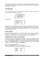
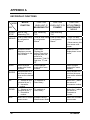
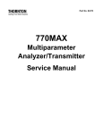
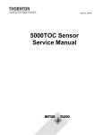
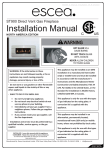
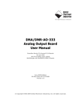
Part No. 84428 550 Total Organic Carbon Analyzer Instruction Manual IMPORTANT SAFETY INFORMATION Please read and observe the following: INSTALLATION: This instrument must be installed by trained instrumentation personnel in accordance with relevant local codes and instructions in this manual. Observe all instrument specifications and ratings. SHOCK HAZARD: Make sure power to all wires is turned off before proceeding with installation or service of this instrument. High voltage may be present on the input power and relay wires. RELAY CONTROL ACTION: Relays will always de-energize on loss of power, equivalent to normal state, regardless of relay state setting for powered operation. Configure any control system using these relays with fail-safe logic accordingly. PROCESS UPSETS: Because process safety conditions may depend on consistent operation of this instrument, take appropriate action to maintain conditions during sensor cleaning, replacement or sensor or instrument calibration. This manual includes safety information with the following designations and formats: WARNING: POTENTIAL FOR PERSONAL INJURY. CAUTION: possible instrument damage or malfunction. NOTE: important operating information SERVICE AND REPAIR INFORMATION This manual provides instruction to properly setup and operate the 550 model TOC Analyzers. Tampering with, modifying, or dis-assembly of any internal components of this analyzer beyond that, which is explicitly spelled out in this manual, is prohibited and will render the manufacturers warranty null and void. TABLE OF CONTENTS CHAPTER 1: GETTING STARTED ................................................................................ 1 INTRODUCTION ........................................................................................................ 1 PRINCIPLE OF OPERATION .................................................................................... 2 CHAPTER 2: INSTALLATION / SET-UP ....................................................................... 4 LOCATION ................................................................................................................. 4 ELECTRICAL CONNECTIONS .................................................................................. 4 SAMPLE TUBING CONNECTIONS ........................................................................... 4 ANALOG OUTPUT..................................................................................................... 5 ALARMS..................................................................................................................... 5 USER INTERFACE/PRINTER.................................................................................... 5 START-UP ................................................................................................................. 6 CHAPTER 3: CONFIGURATION.................................................................................... 8 USER SETUP AND CONFIGURATION MENUS ....................................................... 9 CALENDAR.............................................................................................................. 10 SYSTEM NAME ....................................................................................................... 11 OUTPUT SETUP...................................................................................................... 11 ALARM SETUP, CODES, and SETPOINTS ............................................................ 11 ALARM-X(1 OR 2) MODE CONFIGURATION ......................................................... 12 PRINT SET-UP ........................................................................................................ 12 ANALOG (4-20 mA) OUTPUT.................................................................................. 13 AUTO START........................................................................................................... 13 MEASUREMENT DISPLAY ..................................................................................... 14 AUTOMATIC ZERO CALIBRATION CONTROL ...................................................... 14 PRINTOUT OF CONFIGURATION DATABASE ...................................................... 15 CHAPTER 4: DEMONSTRATION MODE .................................................................... 16 CHAPTER 5: OPERATION .......................................................................................... 17 POWER ON ............................................................................................................. 17 BEFORE MEASURING ............................................................................................ 17 MEASURING............................................................................................................ 17 TREND DATA CLEAR.............................................................................................. 18 PRINT TREND DATA............................................................................................... 18 ALARM SETPOINT SCREEN .................................................................................. 19 ALARM INDICATION ............................................................................................... 19 ERROR CODES....................................................................................................... 20 END MEASUREMENT ............................................................................................. 21 CHAPTER 6: MAINTENANCE ..................................................................................... 22 LAMP REPLACEMENT............................................................................................ 22 CHAPTER 7: CALIBRATION ....................................................................................... 24 ANALOG OUTPUT CALIBRATION .......................................................................... 24 AUTO ZERO CALIBRATION.................................................................................... 25 BOARD CALIBRATION............................................................................................ 25 MEASUREMENT VERIFICATION/CALIBRATION................................................... 29 CHAPTER 8: ADVANCED CONFIGURATION ............................................................ 31 ADVANCED START UP METHODS ........................................................................ 31 VIEWING SENSORS ............................................................................................... 33 TOC CURVE ............................................................................................................ 34 APPENDIX A ................................................................................................................ 36 KEY/DISPLAY FUNCTIONS .................................................................................... 36 SYSTEM CHECK SEQUENCE ................................................................................ 37 550 OPERATION CHART - Measurement Mode ..................................................... 38 550 OPERATION CHART - Setup Mode.................................................................. 39 550 OPERATION CHART - Setup Mode (Maintenance menus) .............................. 40 550 OPERATION CHART - Maintenance Mode (Other Setup menus) .................... 41 OPTIONAL PRINTER DIP SWITCH SETTINGS...................................................... 42 SPECIFICATIONS ........................................................................................................ 43 ACCESSORIES AND REPLACEMENT PARTS .......................................................... 44 CE DECLARATION OF CONFORMITY ....................................................................... 45 DECLARATION OF CSA COMPLIANCE..................................................................... 46 APPLICABLE REQUIREMENTS.............................................................................. 46 WARRANTY ................................................................................................................. 47 CHAPTER 1: GETTING STARTED INTRODUCTION Total Organic Carbon measurement is recognized in many industries as an important, and some cases, required measurement parameter for process certification and performance verification. It is evident that a fast response, easy to operate and maintain, device has recognizable benefits for the user. The Thornton 550 Total Organic Carbon Analyzer provides a faster and easier method of on line measurement. As its predecessor, the 502P, the 550 TOC analyzer units offers the widest dynamic water quality range that can be measured without cumbersome reagents or accessories. And it is the only known TOC Analyzer to measure on-line continuously. The 550 TOC Analyzer is an online device that can be used in a permanent installation and also as a portable device. TOC measurement is capable throughout a range of 0.1 to 1000 ppb for the standard and high temperature models, 0.05 to 30 ppb for the SX model. The Mettler-Toledo Thornton, Inc. factory provides in-house calibrations and testing services and also offers Field Service support (consult local factory sales representatives for details). The Specifications, Principal of Operation, Installation, Configuration, Operation, Maintenance, and Calibration of this unique, high-quality analyzer follow. If you have any questions or comments about this manual, or the analyzer itself, please do not hesitate to contact us. United States Patent (No. 5,518,608) issued. GETTING STARTED 1 PRINCIPLE OF OPERATION The Thornton 550 TOC Analyzer measures Total Organic Carbon in pure and ultrapure water based on differential conductivity. This difference in conductivity is used to determine the amount of organic carbon present. Pressure Control Valve Sample Inlet Inlet Conductivity Sensor (1) Resistivity Sensor (3) UV Oxidation Conductivity Sensor (2) Flow Meter Flow Control Valve Oxidized Sample Outlet CPU Flow Orifice By-pass Sample Outlet Printer (Optional) LCD Display 4-20 mA Analog Output Terminal TOC Temperature Resistivity The sample water enters the analyzer and passes through a pressure regulator, which controls sample pressure to downstream components. Here the sample splits into two flow paths, where a portion of the flow is directed to the by-pass streamline, where resistivity/conductivity and temperature are measured via Sensor (3). These values are represented on the LCD display. The other portion of the sample is directed through a second conductivity sensor, (1), measuring the sample conductivity prior to oxidation. Next, the sample enters the oxidation chamber. As the sample moves through the oxidation chamber, it is subjected to high intensity ultraviolet radiation at 185 nm, effectively oxidizing the sample to CO2. After oxidation, the sample passes through a third conductivity sensor, (2), where the conductivity and temperature are measured again to determine the level of Total Organic Carbon (TOC). The microprocessor of the Thornton 550 TOC Analyzer uses the measured values of initial (1) and final (2) conductivity and temperature to determine the change in compensated conductivity, which is related to the concentration of organic impurity in the incoming water stream. The measurement and sample flow are continuous; therefore, measurement update time is minimized, providing rapid response to any system disturbances. The oxidized sample stream passes through a flow meter, which has a fine flow-control adjustment, and then through the OXIDIZED SAMPLE OUTLET port. This effluent may be sent to waste or recycled. The operating flow rate is typically 20 ml/min, resulting in residence time in the oxidation chamber of less then one minute. The conductivity 2 GETTING STARTED measurements are continuous; therefore, response time is directly related to the residence time of the sample in the oxidation chamber. Values of TOC, resistivity (or alternatively conductivity or uncompensated conductivity), and temperature are displayed on the LCD screen of the instrument. These values can also be printed or sent to a computer through RS-232 serial interface ports on the back panel of the instrument at a user-selectable time interval. The last 255 sets of values are stored in memory at the same time interval for viewing on the screen, or a designated number of these data lines can be printed on a demand basis. Other outputs include a continuous 4-20mA self-powered analog output signal and two configurable potential-free alarm contacts. Refer to the specifications in the back of this manual for details regarding these outputs GETTING STARTED 3 CHAPTER 2: INSTALLATION / SET-UP LOCATION The Thornton 550 TOC Analyzer is to be installed in a dry environment with a relative humidity <80% (non-condensing) and with ambient temperature between 5 and 40°C (41 to 104°F), on a flat, horizontal surface. The sample inlet line should be fitted with an isolation valve. The OXIDIZED SAMPLE OUTLET and BYPASS SAMPLE OUTLET tubes are led to waste (or a water reclaim system) at atmospheric pressure without any obstructions in the tubing. ELECTRICAL CONNECTIONS A power outlet must be available within 3 ft. (1 m) when using the 3-pronged power cord supplied with the analyzer. An adapter for the power cord may be necessary for outlets of different configurations, depending on the country in which the unit is installed. The unit requires a power source between 100 and 240 VAC at either 50 or 60 Hz. Maximum power consumption is 50 W (with optional printer installed). SAMPLE TUBING CONNECTIONS Three pieces of 2.5 m (8 ft) tubing are supplied with the unit. Two pieces are relatively clear and the third (PFA or similar Teflon® material) is opaque. The Teflon® tubing is used for connection from the sample water line to the SAMPLE INLET port on the back panel of the Analyzer. Hardware is to be assembled on the tubing as shown below for connection of the tubing to its port. 4 INSTALLATION / SET-UP The tubing can be shortened to your application. Shorter tubing provides faster response time. Sample water pressure must be a least 0,5 bar (7.0 psi) but not greater than 7 bar (100 psi). A pressure regulator, located inside the Analyzer, protects the spiral quartz tube from damage by excessive inlet pressure. The pieces of clear tubing are to be connected from the BYPASS OUT and from the OXIDIZED OUT ports to the user’s drain at atmospheric pressure, without bends or kinks in the lines. Likewise, these two pieces of tubing can be shortened, although this will have no effect on performance. ANALOG OUTPUT The two terminal connections on the left-hand side of the terminal strip on the back panel can be used for a self-powered 4-20 mA output. This ouput can be configured for remote use of TOC (most common), resistivity, or temperature signal. The maximum load resistance is 500 ohm. ALARMS Two sets of alarm connections, Normally Open, Normally Closed and common, are provided on the same terminal strip. Each alarm can be independently configured as either NO (Normally Open) or NC (Normally Closed). ALARM 1 NO1 COM1 NC1 ALARM 2 NO2 COM2 NC2 Each alarm output is driven by a SPDT relay rated at 0.4A @ 120 VAC or 2.0A @ 30 VDC. See CHAPTER 3: CONFIGURATION for more information. USER INTERFACE/PRINTER Two RS232 connections are available and located on the rear-panel of the analyzer. PRINTER The connection labeled ‘PRINTER’ is a 9-pin, male or female, sub-D connection for connecting an optional printer, with serial interface. The printer port can also be connected to a computer having a serial interface. Communication specifications for this port: 9600 baud; 1 stop bit; no parity; 8-bit data. Software such as hyperterminal, a standard windows based software, may be utilized to collect data with a PC. Mettler-Toledo Thornton, Inc. supplies a small format thermal printer as an optional accessory. A straight-through 9 pin, male or female, sub-D cable is provided with this printer. Configuration (Dip switch settings) for this optional printer can be found in the APPENDIX. An operation manual is also included with the printer. Power for this printer is supplied by the 550 TOC ANALYZER (6 VDC). The power connection is made at the rear of the analyzer. INSTALLATION / SET-UP 5 RS232C The connection labeled “RS232C’ is also a 9-pin sub-D connection for connecting a computer using a serial interface. This port, used in conjunction with a computer having serial interface capability, can be used as an alternate means to collect the operating data from the analyzer. The Computer must have the means to collect this serial data, which will be transmitted in the same format as it is transmitted to the optional printer. The following communication specifications apply. Communication specifications for this port: 2400 baud; 1 stop bit; no parity; 8-bit data. Software such as HyperTerminal, a standard Windows® based software, may be utilized to collect data with a PC. START-UP After all the tubing has been connected, sample water can flow through the unit. Open the user-furnished sample isolation valve. Observe the flow rate from the flow meter on the front panel of the Thornton 550 TOC Analyzer. Adjust the flow rate to the maximum setting by means of the flow adjustment knob, located at the top of the flow meter. If not already installed, connect the power cord to the socket located at the rear of the Thornton 550 TOC analyzer and insure the other end is connected to a suitable power source. Press the power button located at the rear of the analyzer to ON. This will enable the front display screen showing the Thornton name, model # and software version of the analyzer. At this time, the analyzer should be rinsing with sample water to remove any impurity present on the sensors or in the system tubing and components. This will also help remove air bubbles, as any entrained air can cause errors in readings. Upon initial installation and start-up, it is recommended that the analyzer be rinsed for a minimum of 4 hours to 12 hours. The analyzer can be used immediately, but depending on water quality, time may be needed for readings to stabilize. If the desired flow rate is not achievable, the internal pressure regulator may have to be adjusted. With the power to the Analyzer turned off and the power cord disconnected from the power source, remove the top cover. Depress each of the four buttons on opposite sides, just under the lip of the top cover, so that each of the 4 strips on top lifts open. The exposed, large Phillips®-head screws can now be loosened so that the top cover can be removed. Note: There is a proper front and back to the cover. The bottom sides of the cover have male and female grooves, respectively. When replacing the cover, make sure the female groove on the cover lines up with the male mating surface on the housing on one side; the genders will be reversed on the other side. The pressure regulator can be seen toward the back left of the analyzer. First, rotate the flow adjustment knob on the front of the analyzer counterclockwise, to the full open position. Then, on the internal pressure regulator, rotate the knob on the top of the regulator to adjust the pressure until the flow reads 100 ml/min. 6 INSTALLATION / SET-UP After rinsing, use the flow adjustment knob to set the flow to 20 ml/min. CAUTION: Even if no pressure adjustment is required (which is the usual case); the cover should be removed so that the analyzer can be checked for water leaks, as any leak could be a source of error in the readings and also could lead to damage or failure of the unit. When all of these installation steps have been completed, replace the top cover, plug in the power cord, and press the power button, at the rear of the analyzer, to ON. INSTALLATION / SET-UP 7 CHAPTER 3: CONFIGURATION The unit can be configured before or after installation as described in Chapter 2. When the unit is first powered, the following “TITLE” display will be seen. THORNTON 550 TOC Analyzer Ver 1. XX 8 Esc Up Menus Save Next Down Enter Start/ Stop Symbol Name Major function Menus Save Start/ Stop Up Menu key Save key Start measurement Stop measurement Up key Enter menu display Save changes Start measuring TOC Stop measuring TOC Increase number / move the cursor or check mark (*) Down Down key Decrease number / move the cursor or check mark (*) Enter Esc Enter key Escape key Next Next key Enter or exit from a menu line Escape from the current menu level to the previous menu level Scroll the menu displays / move cursor CONFIGURATION The 550 is available in three different models, the standard unit, known simply as the 550 will display the title as shown above. The High Temperature version will show the model number 550-HT and the enhanced resolution version will display the model number 550-SX. The current software version installed is also displayed below the model number. This title screen will also display two other status indicators, when programmed to do so. In the bottom right-hand corner the word “Demo” will flash, indicating that the analyzer has been placed into demonstration mode. Also, it may flash “Auto Start ON,” when the analyzer has been programmed to do so. As shown above the front panel of the 550 provides (8) eight keys for manipulation of the unit’s set-up, configuration, and maintenance menus. See KEYPAD/DISPLAY FUNCTIONS Table in the APPENDIX for a detailed description of the function of each key. USER SETUP AND CONFIGURATION MENUS When the unit is in Standby mode, the first level of menu displays can be accessed by pushing the MENUS key. This array of menus will be used to setup or change the configuration of the 550 TOC Analyzer for normal operation. The 550 software contains a lockout function that when enabled allows configuration changes only if a password is entered. The screens should appear as follows: NOTE: If lockout is enabled (‘Lockout ON’), when pushing the MENUS key from the Title Screen, the next screen will ask for Password Input. The factory default for this password is ‘0000’, (all zeros). The password can be configured for a personalized four-digit password from the Maintenance Menus. Otherwise pushing the Menus key from the Title screen will display the main menus. THORNTON 550 TOC ANALYZER Ver 1.XX Push MENUS key to enter the password screen as shown below: PASS WORD INPUT PASS WORD 0000 (Lock Out ON) Push ENTER Key to view the 1st page of the main menus as shown here: 1.*ALARM – 1 MODE 2. ALARM – 2 MODE 3. ALARM VALUE 4. ALARM DELAY CONFIGURATION 9 Push the NEXT key to view the 2nd page of the main menus as shown here: 5. 6. 7. 8. *PRINT SETUP ANALOG SETUP ANALOG CALIB UV TIME Push the NEXT key again to see the 3rd main menus as shown here: 9. 10. 11. 12. *CALENDAR SETUP SYSTEM CONFIG 1 SYSTEM CONFIG 2 MAINTENANCE The above menus are the (12) twelve main menus used for set-up, configuration and maintenance of the 550 TOC Analyzer CALENDAR First, set the Calendar by pushing the MENUS key. Once at the 1st menu screen, push the NEXT key until you reach the 3rd menus screen shown below: 9. 10. 11. 12. *CALENDAR SETUP SYSTEM CONFIG 1 SYSTEM CONFIG 2 MAINTENANCE If necessary move the * to 9. CALENDAR SETUP using the DOWN key. Press ENTER. Calendar Setup yy/mm/dd *2003/07/20 hh/mm/ss 11:20:35 This is a 24-hour clock. Press ENTER to access the yy/mm/dd fields. Use the NEXT key to move the cursor to the number to be changed. Use the UP/DOWN keys to change the number. After adjusting the date, press ENTER and move the * with the DOWN key to the time. Adjust in the same manner. “SET OK” will flash. Press ESC to return to the previous menu screen. Note: The calendar is backed up by a battery on the printed circuit board. Confirm the time if the unit has not been powered for several weeks. 10 CONFIGURATION Now that the general method of key/display is known, the remaining functions can be easily performed. Refer to the Appendix for a table of KEY/DISPLAY FUNCTIONS and the Operation Flow Charts. SYSTEM NAME Go to “10. System Config 1” (on 3rd page of main menus) by moving the asterisk with the up/ and down keys, until it is on line 10. 9. 10. 11. 12. CALENDAR SETUP *SYSTEM CONFIG1 SYSTEM CONFIG 2 MAINTENANCE Press ENTER. SYSTEM CONFIG 1 Sys Name *0000 Print-T unit min. Program Ver x.xx Press ENTER to highlight the first digit and using the UP, DOWN and NEXT keys, the Sys Name may be set at 0000 or it may be an abbreviated form of the serial number. For example, for S/N 960012, the Sys Name would be 9612. This is arbitrary, and it can be changed by the user. OUTPUT SETUP This section provides instruction for setup of the 550 outputs. If you are using this Analyzer for measurement only, you may proceed to the AutoStart section of configuration. Otherwise, configure outputs as described in the sections below. ALARM SETUP, CODES, and SETPOINTS The Thornton 550 has two independent relay alarms. Each can be configured for one of the three measurement parameters on the display. Choose the parameter and set point. The condition (NO or NC) for each relay is determined by the wiring terminals selected (see INSTALLATION). Configuring the alarms requires the following procedure. There is also a menu tree in Appendix B: From the title screen press MENUS. Move to 1. ALARM MODE-1 or 2. ALARM MODE-2. Press ENTER to reach the following screen display for either alarm: ALARM-1 ITEM = RELAY = HIST. = CONFIGURATION MODE *ppb High On 00 11 ALARM-X (1 OR 2) MODE CONFIGURATION ITEM Select output parameter ppb = TOC Mohm = Resistivity °C = Temperature of sample water ERset = Error None = no output RELAY Definition of relay activation Low Off = Relay off at lower than set point Low On = Relay on at lower than set point High Off = Relay off at higher than set point High On = Relay on at higher than set point If Erset is selected in parameter, relay activation is automatically set to ON HIST. This sets the Hysteresis associated with the alarm set point. A value from 0 to 99 can be entered. HIST. = XX (0 to 99) PRINT SET-UP If an optional printer is used, set up the printing of measurement data as follows: In the MAIN Menus, 2nd screen Select: 5. Print Setup Print Setup Print Time = History Wrt = Nr. Of Data = 01 Sec OFF 0000 Use of History Wrt and Nr. Of Data are explained in OPERATION. Print time is the interval between printing, in seconds, minutes or hours. This display shows an interval of 1. To change this value, move the cursor to the appropriate digit with the NEXT key; then UP or DOWN to change the value. Ranges for print intervals are: 1-99 seconds, 1 - 99 minutes and 1-99 hours, all in increments of 1 (sec., min or hr.). This same time also determines Trend Data display (see OPERATION). To program the units of the Print Time and Trend Data, go to 10.System Configuration 1. Press Enter. SYSTEM CONFIG 1 Sys Name 0000 Print-T unit *sec Program Ver x.xx Using the down key move the cursor to Print-T unit. Press enter. Using the up key change the unit to sec, min, or hour. Press enter. Press save. Select yes by using the 12 CONFIGURATION up key. Press enter. Note: Changing Print-T unit will reset the print time to 01. Press the esc key twice to return to the title screen. ANALOG (4-20 mA) OUTPUT In the MAIN menus, 2nd screen, Select: 6. 4-20 mA SETUP ANALOG SETUP Output = *ppb 4mA Lmt = 000.0 20mA Lmt = 100.0 The Output options are as follow: ppb Mohm °C Hold Not Select None TOC (ppb) Resistivity (Mohm-cm) Temperature (°C) Holds current value (Used for 4-20 mA calibration) Analog signal configured, output not used No configuration, output not used In the above display, the 4-20 mA output is configured for TOC. The 4mA output represents 0.0 ppb TOC, and 20 mA represents 100.0 ppb TOC. These limit values are user selectable with values of 000.0 to 999.9. AUTO START In the MAIN Menus, Refer to 11. SYSTEM CONFIG 2: 9. 10. 11. 12. CALENDAR SETUP SYSTEM CONFIG1 *SYSTEM CONFIG2 MAINTENANCE Press ENTER. SYSTEM CONFIG 2 Auto Start *OFF Print SYS Conf. OFF History Clear OFF When AUTO START is set to OFF, the operator must push START to initiate the measuring process. When it is set to ON, the measurement process begins any time the unit goes from the unpowered to the powered state. (This could be the result of the operator switching the power ON, or from restoration of power after an outage.) It is recommended that this be left OFF for initial operation in a particular application. To change the status insure the asterisk is in front of the OFF on the AUTO START line, press the ENTER key, and use UP/DOWN keys to toggle OFF/ON. Press SAVE to write to memory. CONFIGURATION 13 MEASUREMENT DISPLAY The user has the option of displaying the measurement value of the incoming water sample as resistivity, conductivity, or (temperature) uncompensated conductivity. To change from the default value of resistivity: Go to MEASURE PARA 2, choose 12: MAINTENANCE, Then move the asterisk to 11. Other Setup. After entering Other Setup, set Write to ON to edit Other Setup parameters. MAINTENANCE 4/4 10. A/D View *11. Other Setup Press Enter. Other Setup Write ON Press Enter. Press Next 3 times to go to 4. MEASURE PARA 2 screen. 4. MEASURE PARA 2 RESERVE2 0000 RESERVE3 1000 Sensor Status 0000 In the RESERVE2 line, the codes for measurement display are set by the fourth digit as follows: XXX0 Resistivity (MΩ-cm) XXX1 Conductivity (µS/cm) XXX2 Uncompensated Conductivity (µS/cm) The display will indicate MΩ-cm or µS/cm according to the code selected. AUTOMATIC ZERO CALIBRATION CONTROL Zero calibration is to account for the small differences in measurement between Sensor1 (S1) and Sensor-2 (S2). A zero calibration is performed by the “System Check” routine each time the START button is pushed to start measuring. This is explained in ADVANCED CONFIGURATION. However, the system can be configured to automatically zero-calibrate at set time intervals by use of the first digit from the left in RESERVE2 of MEASURE PARA2, shown above. 14 CONFIGURATION Reserve2 0XXX 1XXX 2XXX 3XXX 4XXX 5XXX 6XXX 7XXX Period of Auto Zero No Auto Zero 20 hours 40 hours 60 hours 80 hours 100 hours 200 hours 1000 hours After changing this parameter, press Save to write it to memory; then switch the power OFF, then ON. Note the following: 1. The second digit of RESERVE2 is used to configure the communication port. The third digit is used for special functions only, and is normally zero. Its function is explained in ADVANCED CONFIGURATION. 2. RESERVE3 is not used and is normally set to 1000. 3. Sensor Status is normally 0000. It is changed only in certain operating situations, as explained in ADVANCED CONFIGURATION. For any application outside the normal operating parameters, please consult Mettler- Toledo Thornton, Inc. technical support department. PRINTOUT OF CONFIGURATION DATABASE A printer attached to the printer port can be used to print out the configuration database. This is advisable for documentation and helpful for troubleshooting. To print out the configuration database: 1. STOP measuring by pressing the START/STOP button. 2. Push Menus and page down to 11. SYSTEM CONFIG 2 using the NEXT and DOWN keys. 9. 10. 11. 12. CALENDAR SETUP SYSTEM CONFIG 1 *SYSTEM CONFIG 2 MAINTENANCE 3. Press ENTER key SYSTEM CONFIG 2 Auto Start OFF Print SYS Conf. *OFF History Clear OFF 4. Select Print SYS Conf. using the DOWN key and pressing ENTER. Toggle ON, using UP/DOWN keys and press ENTER. All configuration parameters in the database will now be printed through the printer port. CONFIGURATION 15 CHAPTER 4: DEMONSTRATION MODE The Thornton 550 can be run in the Demonstration Mode to illustrate and allow practice in changing some of the parameters prior to actual use of the instrument. While the measurement value cannot be changed, other parameters, such as alarm set points, can be altered. To access the Demo Mode, go to 12. DOWN keys. 9. 10. 11. 12. Maintenance, using the Menus, NEXT and CALENDAR SETUP SYSTEM CONFIG 1 SYSTEM CONFIG 2 *MAINTENANCE After entering the Password (FACTORY default is “0000’) using the UP and ENTER keys, the first screen, maintenance 1/4 will display. MAINTENANCE 1/4 *1. Demo Mode On/Off 2. Sensor View 3. EEPROM Setup The default selection is *1. Demo Mode On/Off. ENTER will display the Demo ON/OFF screen as follows: Playing Demo Demo Mark Off Use UP to toggle to ON. Go back to the title screen by pressing the ESC key 3 times. In the lower right corner of the display “DEMO!!” will appear. If it does not the unit is not in demonstration mode. Push the START key, and the System Check cycle will commence. After about 3 min, the display will indicate SYSTEM CHECK PASSED and that the UV is ON. This is for simulation only: the lamp is not actually powered. Then, after about 2 min, the measurement screen appears. Pushing the START/STOP key again returns the display to the TITLE screen. Other functions can be examined and values, such as alarm set points, can be changed for purposes of demonstration. Refer to CONFIGURATION and also the Operation Flow Chart in the APPENDIX. When finished, return to the Playing Demo screen to turn Demo OFF. 16 DEMONSTRATION MODE CHAPTER 5: OPERATION POWER ON Turn on the power at the switch on the rear panel of the Analyzer. THORNTON 550 TOC Analyzer Ver x.xx TITLE Screen will appear as shown. High temperature units display 550-HT and SX units display 550-SX. BEFORE MEASURING Before starting to measure, be sure the flow rate is adjusted to 20 ml/min (unless otherwise specified for your application.) MEASURING Push START to initiate the System Check and Measure process. SYSTEM CHECK is blinking. The analyzer does an automatic zeroing to correct for any drift. SYSTEM CHECK Please Wait RESIST = 18.20 MΩ-cm ↓ SYSTEMCHECK PASSED UV WARMING UP Please Wait RESIST = 18.20 MΩ-cm SYSTEM CHECK PASSED now solid. UV Warming Up is blinking. UV Lamp is stabilizing during this period. ↓ TOC = RES = TMP = 200.32 ppb 18.21 MΩ.cm 25.6 °C Primary Measurement Display. Measurement is updated every 2 seconds. Trend data can be viewed by pushing NEXT. Display. TIME 10:30 11:00 11:30 OPERATION TOC 75.2 100.2 200.6 RES 18.2 17.6 17.2 TP 25 25 25 ESC returns to the Measurement Time interval is determined by Print Setup. See PRINT SETUP. 17 From the above screen, the Measurement Trend Check Mode can be accessed with ENTER. The past record of measurement values can be accessed with UP/DOWN. Pressing ENTER again will show the three most current readings on the display. TIME 10:30* 11:00* 11:30* TOC 75.2 100.2 200.6 RES 18.2 17.6 17.2 TP 25 25 25 255 Lines of data are stored. The values are the instantaneous measurement at the time shown, not an average value. ESC will return the display to the regular Measurement screen. TREND DATA CLEAR If the unit has been moved and a new sample is being introduced, or it is otherwise desirable, the trend data can be erased. First, stop measurement with the START/STOP button. Press Menus key and then access TREND CLEAR in 11. System Config2 using the NEXT and DOWN keys. 9. 10. 11. 12. CALENDAR SETUP SYSTEM CONFIG 1 *SYSTEM CONFIG 2 MAINTENANCE Press ENTER key. SYSTEM CONFIG 2 Auto Start OFF Print SYS Conf. OFF History Clear *OFF Select History Clear using the DOWN key and press ENTER. Toggle to ON using UP/DOWN keys, and press ENTER. The trend data will be cleared. PRINT TREND DATA If a printer is connected to the printer port, the measurement trend data can be printed. Push Menus and move the asterisk to item 5. PRINT SETUP. Press ENTER to enter this menu. 5. 6. 7. 8. *PRINT SETUP ANALOG SETUP ANALOG CALIB UV TIME Press Enter. Print Setup Print Time = History Wrt = Nr. of Data = 18 10 sec OFF *0010 OPERATION Select Nr. Of Data using the DOWN key and press ENTER. Move the cursor using the NEXT key and change to the desired number of most recent data lines you wish to print with the UP/DOWN keys. Press ENTER. Next, select History Write using the UP key, press ENTER and toggle ON using the UP/DOWN keys. Press ENTER. The number of data lines you selected will print out. Push ESC twice to return to the Measurement Display. ALARM SETPOINT SCREEN From the Measurement Screen, the Alarm Set point Screen can be accessed pressing NEXT twice (see APPENDIX). This display shows the set point values for Alarms 1 & 2. These are read-only and cannot ALM1 = 450.5 ppb be changed from this screen. TF and RF are ALM2 = 10.3 Mohm values from 6. TOC Calib in MAINTENANCE T.F = 1.234 R.F = 0.987 2/4. UV TIME is the total number of hours the UV TIME = 200 Hours present lamp has been used. NEXT returns the display to the measurement screen. ALARM INDICATION If an alarm condition is present, or occurs during measurement, an alarm message will appear in the measurement display. For example: TOC = RES = TMP = AL1.H 200.32 ppb 18.21 MΩ 25.6°C UV This indicates that Alarm 1, a high alarm, has been activated. “UV” indicates that the recommended lamp life of 4,000 hours has been exceeded. If a malfunction or abnormality occurs, an error screen will appear, and will alternate with the measurement screen. ERROR 16 TMP1 OVER OPERATION According to the Error Code Table (see below), this indicates the temperature at Sensor-3 (Incoming Sample) is too high. 19 ERROR CODES Message Fault Cause SYSTEM CHECK Unable to measure TOC FAILED Differential between sensors before UV oxidation is too great ERROR 02 Unable to measure TOC Conductivity of sample water is greater than 20 µS/cm ERROR 03 Sensor 1 error Sensor 1 cable not connected, or sensor fault ERROR 08 Sensor 2 error Sensor 2 cable not connected, or sensor fault ERROR 13 Sensor 3 error Sensor 3 cable not connected, or sensor fault ERROR 18 UV lamp life finished Replace UV lamp ERROR 06 ERROR 11 ERROR 16 Sensor 1 temperature error Sensor 2 temperature error Sensor 3 temperature error Temperature Sensor error, or temperature above allowable limit ERROR 07 ERROR 12 ERROR 17 Sensor 1 temperature error Sensor 2 temperature error Sensor 3 temperature error Temperature Sensor error, or temperature below allowable limit Error 02, which prevents measurement, can be overridden using the “Sensor Status” function in MEASURE PARA 2. SEE CHAPTER 8 “ADVANCED CONFIGURATION”. Press SETUP and select item 12. MAINTENANCE by pressing the NEXT and DOWN keys. 9. 10. 11. 12. CALENDER SETUP SYSTEM CONFIG 1 SYSTEM CONFIG 2 *MAINTENANCE Press ENTER, enter the Password, (Factory default is 0000), using the UP and ENTER keys, the first screen, MAINTENANCE 1/4, will display. Using the DOWN/UP keys, select Item 11.Other Setup. MAINTENANCE 4/4 10. A/D View *11. Other Setup Press ENTER. Use UP/DOWN to toggle to ON. Press ENTER. 20 OPERATION Using the NEXT key, select MEASURE PARA 2 screen (fourth screen in ‘Other Setup’ menu) and select Sensor Status using the DOWN key. 4. MEASURE PARA2 RESERVE 0000 RESERVE 0000 Sensor Status *0000 Change Sensor Status from 0XXX to 1XXX by pressing ENTER and UP keys. Refer to ADVANCED CONFIGURATION for more information. END MEASUREMENT To terminate measurement at any time, press START/STOP, and the display will return to the TITLE screen. OPERATION 21 CHAPTER 6: MAINTENANCE LAMP REPLACEMENT The only maintenance that is required on a regular basis is replacement of the UV lamp. When the lamp usage time has reached 4,000 hours, a UV lamp alarm appears on the display. At some point after 4,000 hours, the UV radiation will gradually degrade and eventually will affect the validity of the measurement. WARNING: Do not remove back cover with unit ON or Power to the unit ON. UV light is harmful to the eyes. 1. 2. 3. 4. 5. 6. 7. Stop measuring by pushing the START/STOP key. Switch power OFF. Disconnect the power cord. Allow unit to cool 10 minutes before changing the lamp. Remove the round plate on the back panel of the analyzer. Unplug the UV lamp lead. Pull the lamp straight back, loosening it from its socket, and removing it from the unit. 8. The reverse procedure is used to install the new lamp. Grasp the new lamp at its outboard end, being careful not to touch the glass, and insert the lamp in the socket. If the glass portion of the lamp has been exposed to fingerprints or contaminants, clean the lamp with a high purity grade of methanol and a scratch-free cloth or towel. 9. Replace the round plate. 10. Connect the power cord. 11. Turn power ON. The UV time must now be cleared in the software, so that the timer will start with 0 hours for the new lamp. The UV TIME CLR is accessed as follows: • Press MENUS. • Scroll to 12. MAINTENANCE using the down key. • Press Enter and change Password (Factory Default is 0000) using the UP key. • Select MAINTENANCE 4/4 using UP/DOWN key. • Scroll to 11. Other Setup using the DOWN key. • Press ENTER and Toggle ON using UP/DOWN key. Press ENTER • Press NEXT to access 5. UV TIME: 5.UV TIME UV ON TIME = *0020 UV CHG TIME = 4000 UV TIME CLR = OFF • 22 Select UV TIME CLR using the DOWN key. MAINTENANCE UV TIME UV ON TIME = 0020 UV CHG TIME = 4000 UV TIME CLR = *OFF • • • • Press ENTER and toggle UV TIME CLR to ON using the UP/DOWN key and press ENTER. UV ON TIME will reset to 0000. UV TIME CLEAR will automatically return to OFF after clearing. Press ESC three times to return to TITLE screen. Press START to resume measurement. MAINTENANCE 23 CHAPTER 7: CALIBRATION Four aspects of Calibration are covered in this section. • • • • Analog Output Calibration. This procedure is used to calibrate the analog output loop. Auto Zero Calibration. This is a procedure, performed by the monitor itself, to obtain zero readings of the two TOC sensors and correct for any zero drift. Measurement Verification/Calibration. These are methods for verifying that the current calibration is valid, or to adjust factors for re-calibration. Sensor Board Calibration. This procedure calibrates the main PC board with a set of resistors, and it ensures that the electronics measure resistivity accurately. ANALOG OUTPUT CALIBRATION The analog output loop can be calibrated as follows. From the title screen press the Menus key. Go to 6.ANALOG SETUP. Press Enter. ANALOG SETUP Output = *hold 4mA Lmt = 000.0 20mA Lmt = 500.0 Press ENTER and set the output to hold by using the UP key. Press ENTER It is not necessary to push SAVE, as this is a temporary condition only and should not be written on the EEPROM. Press ESC to exit back to the menu options and, with Down, select 7. ANALOG CALIB Press ENTER ANALOG CALIB. 4 mA LOW = *1000 20mA HI = 1000 HOLD = 00 Since this is a digital device, only 2 points are necessary to calibrate the 4-20 mA output. At HOLD = 00, adjust the 4 mA LOW (otherwise meaningless) number until the output, as measured with a current meter reads 4 mA. At HOLD = 100, do likewise for the 20 mA output value. For calibrating a 4-20 mA analog receiver loop, such as one with a pen recorder, the additional intermediate HOLD values of 25 (8 mA), 50 (12 mA), and 75 (16 mA) can be employed. Adjust the receiver instrument indication to conform to these output values. After completion of the loop calibration, Press ESC and go to 6. ANALOG SETUP and change the Output code from hold. 24 CALIBRATION AUTO ZERO CALIBRATION TOC measurement depends upon the difference in conductivity readings between Sensor 1 and Sensor 2. As with any electronic measurement device, the zero may drift slightly over a period of time. In order to maintain a high accuracy measurement, these two sensors should be auto-balanced. This routine is actually initiated every time the START/STOP key is pressed to start the measurement. This is indicated on the display screen as “System Check.” Also, the instrument can be configured to initiate this routine at specified time intervals. This is achieved by setting the first digit from the left in RESERVE2 of MEASURE PARA2. See APPENDIX A for location of MEASURE PARA2 and AUTOMATIC ZERO CALIBRATION CONTROL for a table of Period of Auto Zero. This Auto Zero Calibration is important for measurement in high-purity water. However, if the resistivity of the water is 10 MΩ-cm or lower, Auto Zero Calibration is not necessary, and the first digit of RESERVE2 should be left at 0. If Auto Start has been set to ON, the Auto Zero Calibration (“System Check”) will commence anytime the unit is switched ON or returns to a powered condition after a power outage. Auto Start is found in SYSTEM CONFIG2. See APPENDIX and CONFIGURATION. For a further explanation of the Auto Zero Routine, refer to ADVANCED CONFIGURATION. BOARD CALIBRATION This section describes a procedure to verify the functionality and accuracy of the electronics within the instrument. The Thornton 550 TOC Analyzer has two sensors for TOC measurement and one sensor for measurement of the incoming water sample. These sensors are connected to the motherboard of the 550. Periodically, the motherboard should be calibrated for optimal performance of the sensors. This should be done just before a calibration verification. A convenient time may be when the UV lamp is changed after 4,000 hours. The resistor set used for this calibration is designated Part No. 139-005 (139-007 for –SX models) and is available from Mettler-Toledo Thornton, Inc. The set consists of the following assemblies: 139-005 Resistor Set 1 each Assembly A: 4 KΩ + 100 KΩ 1 each Assembly B: 4 KΩ + 100 KΩ 1 each Assembly C: Jumper 1 each Assembly D: 2 MΩ + 100 KΩ 1 each Assembly E: 1000 pF, 2MΩ + 100 KΩ CALIBRATION 25 Stop the measurement and remove the top cover. CAUTION: POWER IS LIVE DURING THIS PROCEDURE. Press Menus and select 12. MAINTENANCE using the NEXT and UP/DOWN keys. Press ENTER and change pass word (Factory default is 0000) using the UP key. Press ENTER and select 4. Board Calib in MAINTENANCE 2/4. MAINTENANCE 2/4 *4. Board Calib. 5. Sensor Calib. 6. TOC Calib Press ENTER ↓ BOARD CALIBRATION S1S2 øR KR TH S3 øR MR C TH OPEN Prs Enter ESC Press ESC to terminate this procedure and return to the Title Screen. To proceed, disconnect the Sensor 1 and Sensor 2 cables from the board (see Figure 1). Figure 1 (Printed Circuit Board) MΩ (S3) IN (S1) OUT (S2) After disconnecting S1 and S2 from the board, push ENTER, resulting in these displays: BOARD CALIBRATION S1S2 ∅R KR TH S3 ∅R MR C TH Calibration Doing BOARD CALIBRATION S1S2 ∅Rc KR TH S3 ∅R MR C TH R 4K Press Enter Plug one each of Assembly A and B into the connectors of S1 & S2 (see Figure 2). Figure 2 26 CALIBRATION (Printed Circuit Board) MΩ (S3) IN (S1) OUT (S2) 4 kΩ 100 kΩ Assembly A and B After inserting the resistor assemblies as shown above, press ENTER to result in these displays: BOARD CALIBRATION S1S2 ∅Rc KR TH S3 ∅R MR C TH Calibration Doing BOARD CALIBRATION S1S2 ∅Rc KRc TH S3 ∅R MR C TH R 100K Press Enter Press ENTER again: BOARD CALIBRATION S1S2 ∅Rc KRc TH S3 ∅R MR C TH Calibration Doing BOARD CALIBRATION S1S2 ∅Rc KRc THc S3 ∅R MR C TH Short Press Enter Remove the Resistor Assemblies from S1 and S2 as well as the sensor cable connector for S3. Insert Assembly C into the connector for S3 (see Figure 3). Figure 3 Printed Circuit Board Assembly C MΩ (S3) IN (S1) OUT (S2) Press ENTER resulting in the following display: BOARD CALIBRATION S1S2 ∅Rc KRc THc S3 ∅R MR C TH Calibration Doing BOARD CALIBRATION S1S2 ∅Rc KRc THc S3 ∅Rc MRν C TH R 2M Press Enter Remove Assembly C from the S3 connection and replace with Assembly D (see Figure 4): CALIBRATION 27 Figure 4 (Printed Circuit Board) 2 MΩ 100 kΩ MΩ (S3) IN (S1) OUT (S2) Assembly D Press ENTER resulting in the following display: BOARD CALIBRATION S1S2 ∅Rc KRc THc S3 ∅Rc MR C TH Calibration Doing BOARD CALIBRATION S1S2 ∅Rc KRc THc S3 ∅Rc MRc C TH 2M + 1000p Press Enter Replace Assembly D with Assembly E, which includes a capacitor (see Figure 5): Figure 5 (Printed Circuit Board) 1000 pF, 2 MΩ 100 kΩ MΩ (S3) IN (S1) OUT (S2) Press ENTER, for the following displays: BOARDR CALIBRATION S1S2 ∅Rc KRc THc S3 ∅Rc MRc C TH Calibration Doing BOARD CALIBRATION S1S2 ∅Rc KRc THc S3 ∅R MRc Cc THν R 100K Press Enter Press ENTER again for the following displays: 28 CALIBRATION BOARD CALIBRATION S1S2 ∅Rc KRc THc S3 ∅Rc MRc Cc TH Calibration Doing Press SAVE:Toggle to “YES”. Press ENTER Press ESC Twice. BOARD CALIBRATION S1S2 ∅Rc KRc THc S3 ∅Rc MRc Cc THc Calib END Press SAVE THORNTON 550 TOC Analyzer Ver x.xx Remove Assembly E. Push the sensor connectors back into the plugs on the board. Replace top cover. Push START to resume measurement. MEASUREMENT VERIFICATION/CALIBRATION Periodically, the performance of the Analyzer should be verified. It is recommended that factory trained and qualified personnel perform these services. Typically calibrations are performed at the Factory, however on-site service may also be provided in some cases (consult the Thornton Technical Services for details). Typically the verification procedure is performed at the time of the UV lamp replacement. Refer to MAINTENANCE for the procedure for lamp replacement. Before performing the TOC Verification/Calibration, it is advisable to do a board level calibration followed by a resistivity/temperature sensor verification/calibration. The board level calibration procedure uses resistor sets which are plugged into the sensor sockets on the main board. The procedure for board calibration follows in the next section. The required resistor set, Part No. 139-005, is available from Mettler-Toledo Thornton. The resistivity/temperature sensor verification/calibration, which is performed after the board level calibration, can be best obtained using the values from a recently calibrated resistivity monitor and sensor, such as the Thornton 770MAX system. The measuring point of the 770MAX should be close to the connection point for the Thornton 550. TOC verification/calibration can be performed a number of ways. One method of verification is to install a calibrated 550 TOC analyzer in parallel with the test unit. The results of TOC, Resistivity, and Temperature are compared over a period of time. If the results from the test unit compare favorably with the calibrated 550 TOC unit, within published operating tolerances, the test unit calibration is verified. A second, more extensive TOC calibration, subjects the test unit to a known TOC level. A sample is prepared by adding some suitable reagent into low TOC water, to prepare a sample with known TOC level. CALIBRATION 29 Run the calibration sample through the unit until stable readings are achieved. The instrument value can be adjusted in the following manner. In the second screen of MAINTENANCE Mode, select 6. TOC Calib. MAINTENANCE 2/4 4. Board Calib 5. Sensor Calib *6. TOC Calib Press ENTER TOC Calibration T 2.85 -> 2.85* R 18.10 -> 18.10 T.F. = 1.000 R.F. = 1.000 Select T, and enter the known value of TOC. The processor will compare this to the instrument value and calculate a T.F. (TOC Factor), which is a multiplier, and adjust the instrument reading to conform to the known value. 30 CALIBRATION CHAPTER 8: ADVANCED CONFIGURATION ADVANCED START UP METHODS The CONFIGURATION and OPERATION methods described previously should be adequate for pure and ultrapure waters (resistivity generally in the 10-18 MΩ-cm range) with relatively low levels of TOC. However, at higher levels of TOC, such as encountered in some Reverse Osmosis product water, recycle, and reclaim rinse water, an advanced configuration technique may be necessary for proper operation. The indication that the standard procedure may need modification is if the “System Check” results in a display “SYSTEM CHECK FAILED” rather than advancing to the UV lamp stabilization stage. The purpose of the System Check sequence is to zero out any differences between Sensor 1 and Sensor 2, before the UV oxidation process begins. After the START key is pressed, the system waits for one minute and then examines the absolute difference between the S1 and S2 conductivity readings. If that absolute value is less than Calib No. 1 value (SEE TABLE ON NEXT PAGE), the display will read “System Check OK”. If the difference is not less than Calib No., the system will wait 20 seconds and read the measurement again. If necessary, this step will be repeated a third time. If the System Check is still not OK, the system adopts Calib No. 2 (SEE TABLE ON NEXT PAGE) as the acceptable criterion. It will check up to five times with 20 seconds between attempts. Note: These two calibration values can be seen in the 2nd screen of the ‘Other Setup’ menus: Press Menus and select item 12. MAINTENANCE by pressing the NEXT and DOWN keys. 9. 10. 11. 12. CALENDAR SETUP SYSTEM CONFIG 1 SYSTEM CONFIG 2 *MAINTENANCE Press ENTER, then enter the Password, (Factory default is 0000) using the UP and ENTER keys, the first screen, MAINTENANCE 1 / 4, will display. Use the NEXT button to reach the fourth Maintenance Screen 4/4. Using the DOWN/UP keys, select Item 11.Other Setup. MAINTENANCE 4/4 10. A/D View *11. Other Setup Press ENTER. The ‘Other Setup’ WRITE OFF/ON screen will appear on the display. ADVANCED CONFIGURATION 31 OTHER SETUP WRITE OFF NOTE: Changing the WRITE OFF to ON will allow changes to be the factory settings within the ‘OTHER SETUP’ menu screens. This should only be turned to ON if changes are being made. Using the NEXT key select INITIALIZE CHANGE screen. 2.INITIALIZE CHANGE Calib. No. 1 *0010 Calib. No. 2 0050 The Table below shows the Calib. Numbers for each 550 model. Values are in units of µS/cm, these values are factory set and should not be altered as instrument performance may be affected. Calib. No.1 Calib. No.2 550 550-HT 550-SX 0010 0050 0010 0550 0006 0010 If the System Check fails after five tries, the processor reads the value of S3, which measures the resistivity of the incoming water sample. If the reading of S3 indicates the incoming water is less than 10 MΩ-cm but greater than 0.05 MΩ-cm (<20 µS/cm), the processor will set the absolute value of the difference between S1 and S2 to zero. The System Check will be indicated as “PASSED”. The UV lamp is automatically turned on and allowed to stabilize for approximately 2 minutes. The system then starts measuring and indicating TOC. If the resistivity of the incoming water is <0.05 MΩ-cm (conductivity >20µS/cm), the display will indicate “System Check Failed”. Error 2 is activated, and the unit will not measure TOC. This error indication can be disabled on the 4th screen of OTHER SETUP menus. 4.MEASURE PARA 2 RESERVE2 0000 RESERVE3 1000 Sensor Status *0000 • • • • • • 32 Select Sensor Status using the DOWN key. Press ENTER Using the UP key change Sensor Status from 0000 to 1000 to disable Error 2. Press Save to write this change to the EEPROM. Press ESC to return the display to the TITLE screen. Press START, and after the System Check sequence, the unit will measure and display TOC. If system check fails again, set Reserve2 to 0010 as described on next page. ADVANCED CONFIGURATION If the resistivity of the incoming water is 10 MΩ-cm or above, the System Check not passing indicates there is a problem, and the screen will display “SYSTEM CHECK FAILED.” If this occurs, turn the unit off, then on again, and push the START button to once again initiate the System Check sequence. If the System Check again fails, the “System Check FAILED!!” can be overridden by changing the RESERVE2 in the MEASURE PARA 2 (4th screen in OTHER SETUP menus) as follows: 4.MEASURE PARA 2 RESERVE2 *0000 RESERVE3 1000 Sensor Status 0000 Select RESERVE2 using UP/DOWN key and press ENTER. Change from XX0X Normal System Check to XX1X Special System Check using the NEXT and UP keys. This will override “SYSTEM CHECK FAILED!!” and permit the sequence to advance to the next stage (turn on UV lamp.) This means that the difference between the zero readings of S1 and S2 will not be eliminated and there may be some error in the measured TOC value. This error is usually insignificant in lower quality water (<10 MΩ-cm.) VIEWING SENSORS To view the readings of the individual sensors, press Menus and select 12. MAINTENANCE using the NEXT and UP/DOWN keys. 9. CALENDER SETUP 10 SYSTEM CONFIG1 11. SYSTEM CONFIG2 12. *MAINTENANCE Press ENTER, enter the Password, (Factory default is 0000), using the UP and ENTER keys, the first screen, MAINTENANCE 1/4, will display. Using the DOWN/UP keys, select Item 2. Sensor View and press ENTER. MAINTENANCE 1/4 1. Demo Mode On/Off *2. Sensor View 3. EEPROM Setup ADVANCED CONFIGURATION 33 S1 S2 S3 Press Next This first screen, Sensor View 1/4, shows temperature-compensated conductivity and temperature readings for S1 and S2 (resistivity for S3). Sensor View 2/4 1.49524 5.75341 0.93 Press Next. The second screen shows raw values (not temperature-compensated) of conductivity and resistivity. ↓ [S1] [S2] [S3] Press Next Sensor View 1/4 1.53652 23.75 7.39979 23.35 0.91 23.73 ↓ Sensor View 3/4 TOC CURVE 01 TOC = 82.32 Delta = 5.86327 Press Next Press Next. The third screen indicates the TOC Curve presently in use, the TOC reading and the difference between S1 and S2. ↓ Sensor View 4/4 Now D = 5.86327 Init D = 0.00008 PPB set = *0000 “Now D” – “Init D” = Difference that is converted to TOC. PPB set : Not used In the Sensor View area, it is possible to observe measurements in both the non-oxidizing mode (UV Lamp Off) and in the oxidizing mode (UV Lamp ON). First, the unit must be placed in the non-measuring (Standby) mode by pushing the START/STOP button, which turns off the UV lamp and returns the display to the TITLE screen. Once in non-measuring (Standby) mode, return to the Sensor View area in SETUP, as described above. After sufficient time (about 2 minutes) has been allowed for the UV lamp to stabilize, the delta conductivity in the non-measuring mode (STAND BY) can be observed. This information would be requested in event of a problem where troubleshooting is required. CAUTION: PRESSING THE MENUS KEY WHILE IN SENSOR VIEW, WILL TURN ON THE UV LAMP. THIS FUNCION EXISTS AS A MAINTENANCE TOOL AND IS INTENDED FOR USE BY AUTHORIZED THORNTON SERVICE PERSONNEL ONLY. TOC CURVE In Sensor View screen 3 / 4, the display shows the TOC Curve designation used to determine the TOC value measured by the analyzer. The factory default for all three models, 550/550-HT/550-SX is TOC Curve1 This curve is designed to provide optimum performance for typical sample waters that meet the water quality and TOC range limits specified for these analyzers. In certain circumstances, this Factory default may be changed. These are special cases where a sample water may contain known levels of specific organics, in which 34 ADVANCED CONFIGURATION case a different curve designation may be entered. This alteration will require factory support and should only be performed by factory trained and certified personnel. ADVANCED CONFIGURATION 35 APPENDIX A KEY/DISPLAY FUNCTIONS MODE MAJOR FUNCTION KEY FUNCTION FUNCTION WHEN UNIT IS WHEN UNIT IS IN MEASURING TOC STANDBY FUNCTION WITHIN ITEM 12. MAINTENANCE MENUS START/ STOP Start or Stop Measuring TOC Stop Measuring TOC Start Measuring TOC MENUS Push to enter setup & configuration Menus Push to enter setup & configuration Menus Push to enter setup & configuration Menus NEXT Scrolls the menu displays or moves the Underline to the next location Press Once, Displays the history,Press twice, displays alarm set points of a parameter. Total UV light time, TF, and RF Moves the menu display down/ move cursor SAVE Saves changes made within menu screens Saves changes made within menu screens Saves changes made within menu screens ENTER Allows access to or exit from the menu lines and/or selected items. UP 1. Selects an item (denoted by an *) 2. Increase a number To read data in Data History Moves the (*) within the menus or Increases a number DOWN 1. Selects an item (denoted by an *) 2. Decrease a number To read data in Data History Moves the (*) within the menus or Decreases a number ESC Backs out of current menu screen Escapes back to Measurement Mode Backs out of current menu screen 36 - Turns UV lamp on/off in sensor view - Shows sensor view from sensor calib. screen Allows access to or exit from the menu lines and/or selected items. APPENDIX SYSTEM CHECK SEQUENCE Push START key Push Start/stop Key and Enter Key Simultaneously Wait 3 minutes to stabilize S2-S1 value Sets |S1-S2| = 0 |S1-S2| < CalibNo.1 (See Table in Chap 8) YES SYSTEM CHECK PASS NO Wait for 1 minute UV ON Wait for 2 minutes Check 3 Times TOC measurement displayed |S1-S2| < CalibNo.2 (See Table in Chap 8) YES NO Wait for 1 minute Check 5 Times NO SYSTEM CHECK...FAILED!! APPENDIX 37 550 OPERATION CHART - Measurement Mode MEASUREMENT MODE Flowchart shows Start-up (System Check) sequence and menu screens available during Measurement Mode THORNTON 550 TOC Analyzer Ver x.xx PRESS MENUS Key To Main Menus page START/STOP Calibration SYSTEM CHECK Please Wait RESIST = 18.20 MΩ-cm Setup Parameter Select UP Key (Parameter Select) DOWN Key (Parameter Select) NEXT Key (Parameter Select or Page Down) ENTER Key (Enter after each Parameter Select) SYS CHECK...FAILED!! Push “ Stop” key SYSTEM CHECK PASSED UV WARMING UP Please Wait RESIST = 18.20 MΩ-cm System Check Measurement Result NEXT TOC = 200.32ppb RES = 18.21 MΩ-cm TMP = 25.6°C Alarm Setpoint Screen ESC ALM1 =450.5 ppb ALM2 = 10.3 Mohm TF = 1.234 RF = 0.987 UV TIME = 200 Hours NEXT Measurement Trend Read Only: Values cannot be changed in this display NEXT TIME 10:30 11:00 11:30 TOC 75.25 78.38 79.54 RES TP 18.20 25.0 17.69 25.1 17.25 25.3 TMP = 25.6°C ALM1 H UV Indication of Alarm, or UV replacement When an error occurs during measurement, these two screens alternate ERROR 16 TMP1 OVER NEXT ENTER TOC = 200.32 ppb RES = 18.21 MΩ-cm ENTER Indication of Error Measurement Trend Check Mode TIME 10:30* 11:00* 11:30* 38 TOC 75.25 78.38 79.54 RES TP 18.20 25.0 17.69 25.1 17.25 25.3 Push ENTER Key to indicate *** after the TIME. Then view the past record of measurement values with UP/DOWN Keys. APPENDIX 550 OPERATION CHART - Setup Mode Back to Measurement Mode or Title Screen (press ESC key once) SETUP MODE Up Key....................Numerical Change DOWN Key..............Numerical Change NEXT Key.............Move the Cursor ENTER Key...........Confirm the Set Numerical Value Alarm 1 Setup From Measurement Mode or Title Screen ALARM-1 MODE ITEM = *ppb RELAY = High On HIST. = 00 Item = Chooses parameter to alarm on. Relay = Activation state when setpoint is reached. HIST. = Histeresis Alarm 2 Setup Setup Main menus screen 1/3 1. *ALARM-1 MODE 2. ALARM-2 MODE 3. ALARM VALUE 4. ALARM DELAY ENTER ALARM-2 MODE ITEM = *ppb RELAY = Low On HIST. = 00 Item = Chooses parameter to alarm on. Relay = Activation state when setpoint is reached. HIST. = Histeresis ALARM VALUE Alm 1 = *100.0ppb Alm 2 = 018.0ppb Alarm Value A1 P Hon A2 M Lon ALARM DELAY Alm1 = *00 sec Alm2 = 00 sec Configures Setpoint values Designates what alarm, parameter s and what mode the activated alarm is configured to. Alarm Delay Number of seconds before alarm triggers relay activation Print Setup ESC ANALOG SETUP Output = *ppb 4mA Lmt = 000.0 20mA Lmt = 100.0 Main Menus screen 2/3 5. *PRINT SETUP 6. ANALOG SETUP 7. ANALOG CALIB. 8. UV TIME PRINT SETUP Print Time = *01 min History Wrt = OFF Nr. of Data = 0100 ENTER ANALOG CALIB. 4mA LOW = *1000 20mA HI = 1000 HOLD = 00 UV TIME UV TIME = 2000 UV TOTAL = 04251 ESC Main Menus screen 3/3 For Service 9. CALENDAR SETUP 10. *SYSTEM CONFIG 1 11. SYSTEM CONFIG 2 12. MAINTENANCE ENTER To Maintenance Menu screens 1/4 thru 4/4 (see next page) APPENDIX CALENDAR SETUP yy/mm/dd *2003/06/03 hh/mm/ss 11:31:46 Configures time interval for data pt collection For writing data pts to printer Determines the number of data pts for History Write function Analog Setup For assigning measurement parameter And values of 4 and 20 mA signal See Configuration. Analog Output Calibration Fro 4-20mA Output calibration SEE Chapter 2. Installation For output and loop calibration UV Time Time of operation of present UV lamp Total operating time of Analyzer Calendar Setup Set Date and Time. See Configuration. SYSTEM CONFIG 1 System Configuration 1 Sys Name *1000 Print-T Unit min Program Ver 1.xx System name. See Configuration. Printer time interval in sec/min/hr Current Software version loaded. SYSTEM CONFIG 2 Auto Start *OFF Print SYS Conf OFF History Clear OFF System Configuration 2 If ON, meas. begins when power applied. Toggle ON to print out configuration data. Toggle ON to clear trend history. 39 550 OPERATION CHART - Setup Mode (Maintenance menus) Back to Measurement Mode or Title Screen (Press ESC key twice) MAINTENANCE MODE To MAIN MENUS SCREEN From MAIN MENU SCREEN 3/3 Password Input Playing Demo DEMO Mark OFF Sensor View 1/4 S1 1.53652 S2 1.50887 S3 0.91 23.75 23.35 23.73 Password Input Password 0000 (0000 is Factory Default) NEXT KEY Sensor View 2/4 [S1] 1.49524 [S2] 1.46909 [S3] 0.93 NEXT KEY Sensor View 3/4 TOC CURVE TOC = 82.32 Delta = 5.86352 1 MAINTENANCE 1/4 NEXT KEY *1. Demo Mode On/Off 2. Sensor View 3. EEPROM Reset ENTER KEY EEPRON Reset EEPROM Write ON Sure ?? If do, Press Enter key NEXT KEY Sensor View 4/4 Now D = 0.56854 Init D = 0.00008 PPb set = *0000 BOARD CALIBRATION S1S2 0R KR TH S3 0R MR C TH OPEN Prs Enter ESC Cell 1 Type R. Const TH. Const MAINTENANCE 2/4 *4. Board Calib. 5. Sensor Calib. 6. TOC Calib. IN *0000 1000 1000 TOC Calibration T 2.85→ 2.85∗ R 18.10→ 18.10 T.F= 1.000 R.F= 1.000 Menus Key Lock Out NEXT KEY Cell 2 Type R. Const TH. Const OUT *0000 1000 1000 NEXT KEY Cell 3 Type R. Const TH. Const Mohm *0000 1000 1000 Next Key Factory or Service Use ONLY “Menus” Key Lock Out Lock Out OFF MAINTENANCE 3/4 *7. Lock Out 8. Pass Word Change 9. LCD Contrast Pass word Changes New Pass word 0000 LCD Contrast Contrast 1000 A/D Converter Level 1 1/16 1.23146 MAINTENANCE 4/4 *10. A/D View 11. Other Setup ESC Key ESC Key Other Setup Write OFF USER SETUP 40 APPENDIX 550 OPERATION CHART - Maintenance Mode (Other Setup menus) Back to Measurement Mode (Press ESC key three times) From previous page 1. TOC Curve TOC Curve FLOW Rate Other Setup Menus *01 20 TOC Curve configuration Full Oxidation NEXT Initialize Limit Setup (For Factory or Service use only 2. INITIALIZE Calib. No.1 Calib. No.2 CHANGE *0010 0050 The Calib No.1&2 number is read as 0.010 µS/cm. See Table in Chapter 8. Programmed TOC Curve. NEXT 3. MEASURE PARA 1 Mohm Limitor 1820 RESERVE 1 0000 Measurement Parameter 1 Designates MΩ-cm limit value on display. Reserve not used. To change flow rate, see CONFIGURATION NEXT 4. MEASURE PARA 2 RESERVE 2 0000 RESERVE 3 1000 Sensor Status 0000 Measurement Parameter 2 Multi-functional. See ADVANCED CONFIGURATION. Not used. For enabling or disabling Error 2, see ADVANCED CONFIGURATION. NEXT UV Light Time 5. UV TIME UV ON TIME = *0020 UV CHG TIME = 4000 UV TIME CLR = OFF ON TIME: total hrs present lamp has been on. CHG TIME: recommended limit for lamp. TIME CLR: Sets On Time to zero. NEXT TOC OFFSET 6. TOC OFFSET TOC OFFSET *0000 For Factory or Service use only. NEXT APPENDIX 41 OPTIONAL PRINTER DIP SWITCH SETTINGS Dip Switch Settings for optional Printer model: Seiko DPU414 Software DIP SW1: Switch No. 1 2 3 4 5 6 7 8 Function Setting Meaning Input Method Printing Speed Auto loading CR function DIP SW setting command Print Density Print Density Print Density OFF ON ON OFF ON OFF ON ON Serial High On Carriage return Enable 100% 100% 100% Function Setting Meaning Print Mode ON User-Defined Characters back-up Character type Zero Font International Character Set International Character Set International Character Set International Character Set ON Normal Printing (40 Columns) On ON ON ON ON ON OFF Ordinary Characters 0 American American American American Function Setting Meaning Data Bit length Parity permission Parity condition Flow control Baud Rate Baud Rate Baud Rate Baud Rate ON ON ON ON OFF ON ON ON 8 Bit Without Odd H/W BUSY 9600 bps 9600 bps 9600 bps 9600 bps Software DIP SW2: Switch No. 1 2 3 4 5 6 7 8 Software DIP SW3: Switch No. 1 2 3 4 5 6 7 8 42 APPENDIX SPECIFICATIONS Ambient Temp/Humidity Location Display Analog outputs Outputs Alarm outputs Alarms displayed Voltage / Current Size Weight Sample connections Wetted Parts Printer Print out Printer interval Power 5-40 °C / 5-80% RH Non-condensing Industrial Environment (Indoor) LCD with back-light, displays TOC, resistivity, temperature, and operation/error indications One 4-20mA DC, Output is selectable for TOC or resistivity or temperature Two SPDT contacts for Hi-Alarm, Lo-Alarm and Error Rated 0.4A @ 120VAC, 2.0A @ 30VDC UV lamp replacement Alarm; Error Alarm (both on LCD) 100-240 VAC @ 50 / 60 Hz/50W (max) 12.8” (327 mm) W x 6.6” (167 mm) H x 13.8” (350 mm) D 17.6 lb. (8 kg) 0.25 in (6 mm) tube fittings 316 SS, PVDF, high quality quartz glass Thermal, Serial dot (SEIKO Model: DPU414) TOC, Resistivity, Temperature, Date and Time 1-99 seconds, 1-99 minutes, 1-99 hours (adjustable in increments of 1) 6 VDC (provided by analyzer) TOC Performance Model Designation Measurement Range Repeatability Resolution Detection Limit Linearity (Accuracy)* Water Quality** Resistivity/ Conductivity*** 550-HT 0.1-1000 ppb ± 0.1 ppb< 10 ppb TOC ± 1% > 10 ppb TOC 0.01 ppb 0.1 ppb 1.00 ± 0.05 > 0.5 MΩ-cm < 2.0 µS/cm 0.05-18.2 MΩ -cm (0.055-20 µS/cm) Sample Water Temperature Particle Size Flow Rate Pressure 15-90° < 100 µm 20 ml/min 7-100 psi at Inlet Sample Water MDL(Min. Detection Limit) 0.1 ppb Temperature Accuracy ±0.3°C (RTD in Conductivity sensors) *Values expressed in terms of Slope, defined as TOC recovered vs. TOC injected based on tests performed using samples of known concentrations of organics. **Designates sample water quality requirements to meet stated TOC performance specifications shown. *** Designates range of conductivity measurement only. SPECIFICATIONS 43 ACCESSORIES AND REPLACEMENT PARTS Part No. 139-003 139-005 129-010 129-002 44 Description Thermal Printer, Serial Interface, 6VDC (Supplied with power cord, interface cable with connectors and manufacturers user’s manual.) Resistor Kit, Board Calibration (550-HT) Replacement UV Lamp, 185 nanometer Replacement Power Cord, three-prong, 1.5 m (5 ft) long ACCESSORIES AND REPLACEMENT PARTS CE DECLARATION OF CONFORMITY We, Mettler-Toledo Thornton, Inc., 36 Middlesex Turnpike, Bedford, MA 01730 hereby declare, in conjunction with the original equipment manufacturer that all 550 TOC Analyzers to which this declaration relates, is in conformity with the following European, harmonized and published standards at the date of this declaration: EN 61326 IEC 61010-1 Emissions (EN 55011 Group Class A) and Immunity Safety (LVD) This declaration is based on complete test data and technical documentation relating to the tests performed per above standards, as noted. CE DECLARATION OF CONFORMITY 45 DECLARATION OF CSA COMPLIANCE Declaration of CSA Compliance Mettler-Toledo Thornton, Inc., 36 Middlesex Turnpike, Bedford, MA 01730 hereby declares that all 550 TOC Analyzers are eligible to bear the official CSA Mark, as shown below, with the adjacent indicators ‘C’ and ‘US’ and a Certificate of Compliance from the Canadian Standards Association has been issued and is on file. Listed below is the detailed information noted on this certificate. PRODUCTS CLASS 2252-03 PROCESS CONTROL EQUIPMENT CLASS 2252-83 PROCESS CONTROL EQUIPMENT – Certificate to U.S. Standards APPLICABLE REQUIREMENTS CSA Standard C22.2 No. 0-M92 - General Requirements – Canadian Electrical Code, Part II 0.4-M1982 - Bonding and Grounding of Electrical Equipment (Protective Grounding) 1010.1-92 - Safety Requirements of Electrical Equipment for Measurement, Control and Laboratory Use, Part 1: General Requirements (Includes Amendment 1) 1010.1B-97- Amendment 2 to CAN/CSA-C22.2 No. 1010.1-92, “Safety Requirements for Electrical Equipment for Measurement, Control, and Laboratory Use, Part 1: General Requirements” ANSI/ISA S82.01-1994- Safety Standards Electrical and Electronic Test, Measuring, Controlling and Related Equipment – General Requirements TIL I-29A - Process Control equipment The ‘C’ and ‘US’ indicators adjacent to the CSA Mark signify that the product has been evaluated to the applicable CSA and ANSI/UL standards, for use in Canada and the U.S> respectively. This ‘US’ indicator includes products eligible to bear the ‘NRTL’ indicator, i.e. National Recognized Testing Laboratory, is a designation granted by the U.S. Occupational Safety and Health Administration (OSHA) to laboratories which have been recognized to perform certification to U.S. Standards. 46 DECLARATION OF CSA COMPLIANCE WARRANTY This Warranty is given expressly and in lieu of all other warranties, express or implied. The Buyer agrees that there is no warranty of merchantability and that there are no other warranties, express or implied, which extend beyond the description on the face of this agreement. Mettler-Toledo Thornton, Inc. (hereinafter referred to as The Company) warrants to the original Buyer each electrode, component, or instrument manufactured and/or sold by The Company to be free from defects in material and workmanship in normal use and service for a period of one (1) year from shipment, unless expressly stated otherwise by the product packaging or expressly agreed to in advance by the Company. The obligation of The Company under this warranty is limited to repair or replacement of the defective product at The Company’s discretion. All warranty claims shall be returned to The Company pursuant to The Company’s Returned Goods Authorization program. Shipping costs (including return shipping) are the responsibility of The Buyer. The Company assumes no responsibility for any direct or indirect costs associated with removal of defective products, or re-installation of replacement products. The Company shall not be responsible for damage to any electrode, component, or instrument resulting from misuse, negligence, accident or resulting from repairs, alterations, or installations made by any person or firm not duly authorized by The Company. No agent is authorized to assume for The Company any liability except as above set forth. The Company warrants that services will be performed in a workmanlike manner in conformity with standard industry practice. Should any nonconformity be detected within 30 days after the work is completed and prompt notification is made by Buyer in writing to the Company, Company will supply the necessary service, direction, or consultation to correct the nonconformity. Returned Goods Policy: A Returned Material Authorization (RMA) number must accompany all returned goods. This authorization is obtained by calling our Technical Service (800) 510-7873 or (781) 301-8600. All transportation costs on authorized returns must be prepaid. Authorized replacement parts sent prior to receipt and evaluation of merchandise being returned will be invoiced in full. Credit will be issued only after the returned part is received and evaluated by factory personnel. The Company is not responsible for products returned without proper authorization. Factory Restocking Charge: Items returned to The Company more than 30 days after shipment will be subject to a 25 % restocking charge, plus any additional charges for refurbishment to salable condition. The Company will not accept returns more than 90 days after shipment, unless returned under warranty or for non-warranty repair. Special Products: Cancellation or return of special products will not be accepted. Disclaimer of Damages: In no event shall The Company be liable for any type of special consequential, incidental or penal damages, whether such damages arise out of or are a result of breach of contract, warranty, tort (including negligence), strict liability or otherwise. Such damages shall include, but not be limited to loss of profits or revenues, loss of use of the equipment or associated equipment, cost of substitute equipment, facilities, down time costs, increased construction costs or claims of The Buyer’s customers or contractors for such damages. The Buyer agrees that in the event of a transfer, assignment, or lease of the equipment sold hereunder The Buyer shall secure for The Company the protection afforded to it in this paragraph. WARRANTY 47 Mettler-Toledo Thornton, Inc. 36 Middlesex Turnpike Bedford, MA 01730 Tel. +1-781-301-8600 Fax +1-781-301-8701 Toll Free +1-800-510-PURE [email protected] Part 84428 Rev.B 02/08 www.mt.com/thornton