1
User's Manual
for
LTC - 21 Temperature Controller
By:
Instrument and Systems Group
Beltsville, Maryland
USA
copyright 1999
Model LTC-21 Cryogenic Temperature Controller
NEOCERA, Inc. Part Number 3000-140
Revision Record
Date
Revision
Description
May 21, 1997
A
Initial Release
October 1, 1997
B
First Neocera Release
August 19, 1999
C
Revised QRMP & SRMP
1999 by NEOCERA Instrument and Systems Group
All rights reserved. No part of this manual may be reproduced, stored in a retrieval system,
or transmitted in any form or by any means, electronic, mechanical, photocopying, recording,
or otherwise, without prior written permission of NEOCERA Inc.
NEOCERA Inc. reserves the right to change the functions, features, or specifications of its
products at any time, without notice.
Any questions or comments in regard to this product and other products from NEOCERA
Instrument and Systems Group., please contact:
NEOCERA INC.
Instrument and Systems Group
10000 Virginia Manor Road, Suite
300
Beltsville, Maryland 20705-4215
U. S. A.
Customer Service and Technical
Support:
1 (800) 290 - 4322 (Within U.S.A.)
1 (301) 210 - 1010 (Outside
U.S.A.)
Fax: 1 (301) 210 - 1042
Cernox™ , ThermOx™ are registered trademarks of Lakeshore Cryotronics Inc.
Page ii
NEOCERA Instrument and Systems Group
Model LTC-21 Cryogenic Temperature Controller
WARRANTY
NEOCERA Limited Warranty
NEOCERA Inc. warrants this product for a period of twelve (12) months from date of
original shipment to the customer. Any part found to be defective in material or
workmanship during the warranty period will be repaired or replaced without charge to the
owner. Prior to returning the instrument for repair, authorization must be obtained from
NEOCERA Inc. or an authorized NEOCERA service agent. All repairs will be warranted
for only the remaining portion of the original warranty, plus the time between receipt of the
instrument at NEOCERA and its return to the owner.
This warranty is limited to NEOCERA’S products that are purchased directly from
NEOCERA, its OEM suppliers, or its authorized sales representatives. It does not apply to
damage caused by accident, misuse, fire, flood or acts of God, or from failure to properly
install, operate, or maintain the product in accordance with the printed instructions provided.
This Warranty Is In Lieu Of Any Other Warranties, Expressed Or
Implied, Including Merchantability Or Fitness For Purpose, Which Are
Expressly Excluded. The Owner Agrees That NEOCERA'S Liability
With Respect To This Product Shall Be As Set Forth In This Warranty,
And Incidental Or Consequential Damages Are Expressly Excluded.
NEOCERA Instrument and Systems Group
Page iii
Model LTC-21 Cryogenic Temperature Controller
Warnings
WARNING:
TO PREVENT SHOCK AND FIRE HAZARDS, AS WELL AS DAMAGE
TO THE LTC-21, IT SHOULD NOT BE ALLOWED TO GET WET OR
OPERATE IN A CONDENSING ATMOSPHERE.
WARNING:
Never attempt to operate the LTC-21 at a different input line
voltage than is shown on the power input module on the rear
panel. Serious injury or equipment damage may result.
WARNING:
ALWAYS REPLACE THE FUSE WITH THE CORRECT VALUE TO
PREVENT SHOCK AND FIRE HAZARDS, AS WELL AS DAMAGE TO
THE LTC-21.
WARNING:
TO PREVENT SHOCK AND FIRE HAZARDS, ALWAYS CONNECT
THE POWER CORD TO A THREE-CONDUCTOR, GROUNDED
RECEPTACLE.
WARNING:
WITH PROPER VENTILATION, THE LTC-21 IS DESIGNED TO
OPERATE INDEFINITELY WITHOUT DAMAGE TO ITSELF IF ITS
HEATER OUTPUT IS SHORT CIRCUITED. HOWEVER, CARE
SHOULD BE TAKEN TO AVOID THIS CONDITION SINCE THE 50
WATT OUTPUT COULD DAMAGE OTHER COMPONENTS OR
RESULT IN A FIRE HAZARD.
WARNING:
IF THE INSTRUMENT IS USED IN A MANNER NOT SPECIFIED BY
THE MANUFACTURER, THE PROTECTION PROVIDED BY THE
EQUIPMENT MAY BE IMPAIRED.
Page iv
NEOCERA Instrument and Systems Group
Model LTC-21 Cryogenic Temperature Controller
Definition of international symbols for warnings and
hazards.
CAUTION, RISK OF ELECTRICAL SHOCK
REFER TO ACCOMPANYING DOCUMENTS
PROTECTIVE EARTH GROUND
NEOCERA Instrument and Systems Group
Page v
Model LTC-21 Cryogenic Temperature Controller
Table of Contents
Warnings................................................. iv
Definition of international symbols for warnings and
hazards.................................................. v
1. Introduction.......................................... 1
1.1.Features........................................ 1
1.2. Specifications................................. 4
1.2.1. Input Channel Specifications............ 4
1.2.1. Output Specifications................... 5
1.2.2. Accuracy Specifications................. 8
1.2.3. Relay and Alarm Outputs................. 9
Relay Outputs............................. 9
Audible Alarm............................. 9
1.2.4. Remote Interfaces....................... 9
IEEE-488 Interface........................ 9
RS-232 Interface.......................... 9
1.2.5. Mechanical, Form Factors................ 9
1.2.6. Power................................... 10
1.2.7. Environmental........................... 11
2. Installation.......................................... 13
2.1. Unpacking And Inspection....................... 13
2.2. Rear Panel Layout.............................. 13
2.3. Power Requirements............................. 14
2.3.1. Fuse.................................... 15
2.3.2. Grounding And Shielding................. 15
2.4. Heater Connection.............................. 15
2.4.1. Heater Wiring........................... 15
2.4.2. Heater Selection........................ 16
2.4.3. Analog Output Connection................ 17
2.5. Sensor Connection.............................. 17
2.6. Relay Connection............................... 18
2.7. Interface Connection........................... 18
2.8. Mounting The LTC-21............................ 18
3. Operation............................................. 19
3.1. Use of the Keyboard............................ 19
3.2. LOCAL Key...................................... 19
3.3. FUNCTION Keys.................................. 19
3.3.1. CONTROL................................. 19
3.3.2. MONITOR................................. 19
3.3.3. SETUP................................... 19
3.4. DATA ENTRY Keys................................ 19
3.4.1. Cursor Keys............................. 19
3.4.2. INC (Increment) and DEC (Decrement) Keys 19
3.4.3. Numeric Keypad.......................... 20
Page vi
NEOCERA Instrument and Systems Group
Model LTC-21 Cryogenic Temperature Controller
4.
5.
6.
7.
3.4.4. BACKSPACE ..............................
3.4.5. CLEAR ..................................
3.4.6. ENTER ..................................
3.4.7. EXIT ...................................
3.5. Special Key Assignments .......................
3.6. Menu Tree .....................................
Initial Power Up Sequence And Display ................
Operating Modes ......................................
5.1. Introduction To The Three Operating Modes .....
5.2. Monitor Mode: Monitoring Temperature With The
LTC-21 .............................................
5.2.1. Using the Monitor Mode. ................
5.2.2. Changing the SET POINT .................
5.2.3. Relays and Alarms in Monitor Mode ......
5.2.3.1. Control Mode: Regulating
Temperature With The LTC-21 ..............
5.3. Setup Mode: Configuring The LTC-21 ............
5.3.1. Introduction To The Setup Mode .........
5.3.2. Instrument Setup Selection Menu ........
5.3.3. Display Configuration Menu .............
5.3.4. Set Display Units Menu .................
The Effects of Changing Display Units ....
Input Filter Time Constant Menu ..........
5.3.5. Datalog ...............................
5.3.6. Sensor Configuration Menu ..............
5.3.7. Output Configuration Menu ..............
Introduction to Configuring the Outputs ..
SENSOR Menu Field ........................
MODE Menu Field ..........................
MAX PWR Menu Field .......................
Ramp Menu Field ..........................
5.4.8. Misc Menu ..............................
5.3.8. Alarm & Relay Set Points ...............
5.3.9. Remote I/O Config. .....................
5.3.10. Sensor CAL Tables .....................
5.3.11. Entering a New Sensor Table ...........
5.3.12. Viewing and Editing a Sensor Table ....
5.3.13. Deleting a User Table .................
5.3.14. The Instrument Calibration Menu .......
5.3.15. Input / Output Tests Menu .............
PID Theory And Tuning Tips ...........................
6.1. The LTC-21 PID Mode ...........................
6.2. Selecting Coefficients ........................
6.3. Fine Tuning the Coefficients ..................
6.4. Ramping .......................................
Using Autotune .......................................
NEOCERA Instrument and Systems Group
20
20
20
20
20
21
23
25
25
25
25
26
27
27
28
28
29
30
30
30
31
32
32
33
33
34
34
39
39
40
40
41
42
42
46
47
48
48
51
51
51
52
52
55
Page vii
Model LTC-21 Cryogenic Temperature Controller
7.1. Introduction................................... 55
7.2. AUTOTUNE Basics................................ 55
7.3. Advanced Usage of AUTOTUNE..................... 57
8. Using Data Log........................................ 59
8.1. Introduction................................... 59
8.2. DATA LOG Function.............................. 59
8.2.1. DATA LOG SETUP......................... 59
Sample Interval field..................... 60
Sensor Channel field...................... 60
Total Samples/Channel field.............. 60
Acquisition Mode field.................... 60
Current Time field........................ 61
8.3. Display Datalog................................ 61
9. Model LTC-21 Functional Description................... 63
9.1. Block Diagram.................................. 63
9.2.Operation....................................... 65
10. Instrument Adjustments, Self Test and Calibration
Procedures............................................... 67
10.1. Display Contrast Adjustment................... 67
10.2. Backdoor Modes................................ 67
10.2.1. Clearing Non-Volatile RAM.............. 67
10.2.2. Entering Instrument Recalibration Mode. 68
10.3. Self Test..................................... 68
10.3.1. LED Tests.............................. 68
10.3.2. Analog Output Channel Tests............ 68
10.3.3. Heater Output Channel Tests............ 69
10.4. Heater Power Output Channel Calibration....... 69
10.5. Checking Sensor Calibration................... 70
10.6. Calibration Procedure, Sensor Channels........ 71
Appendix A: Remote Interface Commands:................... 73
*CLS........................................... 76
*OPC........................................... 76
*RST........................................... 77
*SRE........................................... 77
*WAI........................................... 77
IEEE Query Command Reference........................ 78
*ESE?.......................................... 78
*ESR?.......................................... 78
*IDN?.......................................... 78
*OPC?.......................................... 79
*SRE?.......................................... 79
*STB?.......................................... 79
LTC-21 Commands Reference........................... 80
SACONT......................................... 80
SADDR.......................................... 80
SARTBL......................................... 80
Page viii
NEOCERA Instrument and Systems Group
Model LTC-21 Cryogenic Temperature Controller
SCALT .........................................
SCONT .........................................
SDLC ..........................................
SDLI ..........................................
SDLM ..........................................
SDLS ..........................................
SDLT ..........................................
SDUR ..........................................
SETP ..........................................
SHCONT ........................................
SHMXPWR .......................................
SLLOCK ........................................
SMON ..........................................
SOSEN .........................................
SPID ..........................................
SPTBL .........................................
SPTBNDX .......................................
SRMP ..........................................
STOD ..........................................
SSTYPE ........................................
STUNE .........................................
STUNEP ........................................
SUERREG .......................................
SUNIT .........................................
DCALT .........................................
QADDR? ........................................
QARTBL? .......................................
QDLB? .........................................
QDLC? .........................................
QDUR? .........................................
QHEAT? ........................................
QISTATE? ......................................
QLLOCK? .......................................
QOUT? .........................................
QPID? .........................................
QPTBNDX? ......................................
QRMP ..........................................
QSAMP? ........................................
QSETP? ........................................
QSTYPE? .......................................
QTBL? .........................................
QTOD? .........................................
QTUNEP? .......................................
QUERREG? ......................................
QUNIT? ........................................
Appendix B: IEEE 488.2 Example Programs ................
NEOCERA Instrument and Systems Group
81
82
82
82
83
83
83
83
84
84
85
85
86
86
86
87
87
87
87
88
89
89
90
90
91
91
91
92
93
94
94
94
95
95
96
96
96
96
98
98
99
99
100
100
100
103
Page ix
Model LTC-21 Cryogenic Temperature Controller
Appendix C: Interface Connector Pinouts................. 107
Relays.............................................. 107
Sensors............................................. 107
Analog Output:...................................... 110
Heater:............................................. 110
Appendix D: Application Notes........................... 111
Procedure to interface with LTC-21 using Windows 3.1
Terminal............................................ 111
Procedure to Transfer Datalogged data to PC using
PROCOMM for DOS..................................... 117
INDEX.................................................... 119
Page x
NEOCERA Instrument and Systems Group
Model LTC-21 Cryogenic Temperature Controller
Table of Tables
Table
Table
Table
Table
Table
Table
Table
Table
Table
Table
Table
Table
Table
Table
Table
Table
Table
Table
Table
Table
Table
Table
Table
Table
Table
Table
Table
Table
Table
Table
Table
1 Sensor Accuracy vs Sensor Excitation ................ 8
2 ac Fusing .......................................... 15
3 Conditions for Linear Operation of Heater .......... 16
4 LTC-21 Supported Sensors ........................... 33
5 Output Configuration Options ....................... 34
6 PID Modes .......................................... 36
7 Misc Menu Selections ............................... 40
8 Relay Connector Pin Assignment ..................... 41
9 Excitation/Accuracy/Resistance Range ............... 43
10 Sensor Type Selection ............................. 44
11 Cal Table Units ................................... 44
12 Autotune Process Time ............................. 57
13 Datalog Configuration Selections .................. 60
14 IEEE Remote Interface Commands .................... 75
15 IEEE Analog Output Channel Control Information .... 80
16 IEEE Sensor Calibration Selections ................ 81
17 IEEE Heater Output Channel Control Mode Selection . 84
18 IEEE Maximum Heater Output Selection .............. 85
19 IEEE Sensor Type Selection ........................ 88
20 IEEE SUERREG Command Error Register Bit Definition 90
21 IEEE SUERREG Execution Error Register Bit Definition90
22 IEEE Standard Cal Table/Sensor Type Indices ....... 98
23 IEEE Standard and User Tables Contents ............ 99
24 QUERREG? Command Error Register Bit Definition ... 100
25 QUERREG? Execution Error Register Bit Definition . 100
26 Relay Connector Pin-out .......................... 107
27 Sensor Connector Pin-out ......................... 109
28 CryoCal Silicon Diodes Wire Color Codes ......... 110
29 Analog Output Pin-out ............................ 110
30 Heater Connector Pin-out ......................... 111
31 RS-232 Settings .................................. 112
NEOCERA Instrument and Systems Group
Page xi
Model LTC-21 Cryogenic Temperature Controller
Table of Figures
Figure
Figure
Figure
Figure
Figure
Figure
Figure
Figure
Figure
Figure
Figure
Figure
Figure
Figure
Figure
Figure
Figure
Figure
Figure
Figure
Figure
Figure
Figure
Figure
Figure
Figure
Figure
Figure
Figure
Figure
Page xii
1 Four-Wire Sensor Connection......................... 5
2 Heater Connection................................... 6
3 LTC-21 Rear Panel.................................. 14
4 Menu Tree.......................................... 21
5 ADC Calibration Screen............................. 23
6 Monitor Mode Screen................................ 26
7 Setpoint Screen.................................... 27
8 Control Mode Screen................................ 28
9 Setup Screen....................................... 29
10 Display Configuration Screen...................... 30
11 Display Units Screen.............................. 30
12 Display Update Rate Screen........................ 31
13 Sensor Configuration Screen....................... 32
14 Output Configuration Screen....................... 33
15 PID Mode Screen................................... 35
16 Table Mode Screen................................. 37
17 Ramp Configuration Menu........................... 39
18 Misc Menu Screen.................................. 40
19 Alarm & Relay Setup Screen........................ 41
20 Remote Input/Output Configuration Screen.......... 42
21 Sensor Parameters Screen.......................... 42
22 Sensor Calibration Edit/View Screen............... 45
23 Sensor Cal Table Menu Screen...................... 47
24 Input/Output Tests Menu Table..................... 48
25 Datalog Configuration Screen...................... 59
26 Datalog Display Screen............................ 61
27 LTC-21 Functional Block Diagram................... 63
28 LTC-21 Sensor Calibration Fixture................. 71
29 Platinum Sensor Four-wire Connection............. 109
30 DT-470 Sensor Four-wire Connection............... 109
NEOCERA Instrument and Systems Group
Chapter 1
Introduction and Specifications
1. Introduction
1.1.Features
The LTC-21 is a high-performance temperature controller designed for use with most
cryogenic temperature sensors. It has a wide range of features and capabilities that allow it to
outperform competitive models in nearly every application. The LTC-21 is designed to
accommodate the use of unusual sensors with higher resolution at ultra-low temperatures.
The LTC-21 features include:
Two, Multi-Purpose Inputs The standard input modules supplied with the LTC-21
support all common cryogenic sensors, including:
•
Silicon and GaAlAs diodes (from 1 K to about 400 K),
•
Carbon, carbon-glass, ThermOx™, CernoxTM, Ruthenium Oxide and
germanium resistors (from less than 0.3 K to about 300 K),
•
Platinum and RhFe RTDs of any resistance (from about 12 K to 500 K).
Digital control
The LTC-21 temperature controller is based on a fast, 32-bit microprocessor that uses
advanced digital signal processing techniques to implement a completely digital
temperature control loop.
Accurate
Use of high resolution Analog-to-Digital (20-bit) converter
on all input channels and Digital-to-Analog (16-bit)
converter on output channels ensures accuracy and smooth,
continuous control.
A high loop sample rate (16 Hz) completely prevents instability due to temperature
aliasing and allows the use of digital filters to further improve both display and control
accuracy.
Performing all internal arithmetic computations in 32-bit IEEE compatible floating point
format ensures that no accuracy is lost due to computational errors.
Sensor data is interpolated based on sensor calibration tables using a Cubic Spline
algorithm.
NIST Traceable Calibration
Factory instrument calibration performed to a NIST traceable standards.
NEOCERA Instrument and Systems Group
Page 1
Model LTC-21 Cryogenic Temperature Controller
Variable ac and dc Sensor Excitation
A wide range of dc and ac sensor excitations are possible. Diode sensors are biased with
10 µAmp dc, constant-current excitation. Linear sensors such as Platinum (Pt) and
Rhodium-Iron (RhFe) sensors can use ac or dc with the same range of excitation. ac
constant-voltage excitation may be used with Carbon, Germanium, and other resistive
sensors. Using this constant voltage excitation, the power dissipated in the sensor is kept
at very low levels, minimizing any self-heating at low temperatures ( high resistances).
There are 7 constant voltage excitation outputs in the LTC-21; 10.0mV, 3.0mV, 1.0mV,
320µV , 100µV, 32µV , and 10µV peak-to-peak. This feature enables the instrument to
measure resistances from 1Ω to 1 MΩ with very low power dissipation.
Calibration Curves
Standard calibration curves are stored for several sensor types supplied by the major
cryogenic sensor manufacturers, including LakeShore Cryotronics, Scientific
Instruments, and CryoCal. Up to 16 additional user defined curves may also be
entered into non-volatile memory. There may be up to 149 points per table and they are
easily entered from the front panel or downloaded over one of the two remote interfaces.
The standard tables supplied can be easily modified to adjust for one or two or three
point calibrations of your actual sensor.
Dual Heater Outputs
The LTC-21 has two standard outputs: A 50 Watt heater and an Analog Output. Each of
the two input channels may be configured to control either heater output.
The 50 Watt heater is a Constant-Current-Source type that can output up to 1.0A at up to
50V. Constant current is used to ensure that the port is short-circuit protected. When
used with a 50W heater element, the corresponding maximum output power will be
50W. This output also has four user selectable ranges so that 50W, 5W, 0.5W or 0.05W
may be selected as the maximum output power.
The second output is the Analog Output channel. This is a voltage type output that can
be configured as a monitor or as a low power heater. In either case, it will output a
maximum of ±12V at up to 100mA.
When used as a monitor, the Analog Output can be connected to recording devices
including chart recorders. In this mode, user specified offset and gain parameters are
applied to input temperature data in order to generate an analog output voltage.
If the Analog Output is configured as a control heater, PID coefficients are applied to
generate the output voltage level.
Remote Control: IEEE-488 and RS-232 Interface Ports.
The LTC-21 is designed for incorporation in automated systems using either IEEE-488
or RS-232 interface ports. Both ports are supplied as standard features. Full computer
control of all front panel functions is possible. Sensors readings and instrument status
can be read remotely using either or both ports.
Page 2
NEOCERA Instrument and Systems Group
Model LTC-21 Cryogenic Temperature Controller
Alarms
Both channels have audible alarms with user programmable high and low limits.
Relay Outputs
Relays are supplied on both channels with separately programmable, high and low
temperature set points. They may be used to control external equipment based on
temperature range. Relay contacts are rated at 0.5A, 30Vrms or 60VDC.
Control Algorithms.
A wide range of control algorithms simplify regulation of even the most difficult
cryogenic systems. The LTC-21 has three AUTOTUNE modes that can regulate the
most difficult systems over wide temperature ranges with no operator intervention. Full
manual control of PID coefficients is possible. PID tables are available to store
optimized parameters vs. setpoint.
Control Set Points.
Regulation set points can be entered with 0.001 K resolution over the entire operating
range and 0.0001K below 10K for all calibrated sensors. For uncalibrated sensors, or
calibrated sensors that are displayed in ohms or volts, the Set Points can be entered with
six-digit resolution.
Resolution and Accuracy.
The temperature resolution and accuracy of the LTC-21 are usually limited by the sensor.
The limitations imposed by the LTC-21 are discussed in the Instrument Specifications
section.
NEOCERA Instrument and Systems Group
Page 3
Model LTC-21 Cryogenic Temperature Controller
1.2. Specifications
1.2.1. Input Channel Specifications
There are two temperature sensor input channels, each of which can separately be configured
to use any of the supported sensor types.
Types of Sensors Supported
Supported Sensors include:
•
•
•
•
•
•
•
•
Silicon and GaAlAs diodes
GRT's.
Carbon-Glass and Carbon-Composite.
CernoxTM Resistors
Ruthenium Oxide Resistors
Germanium Resistors
Rhodium-Iron.
Platinum RTDs (Alpha types and arbitrary resistance at 300 K).
•
ThermOx™ Resistance Sensors
Additionally, pre-loaded standard calibration curves are supplied for the following
sensors:
•
•
Pt (100, 1000)
Si diode thermometers (Lake Shore, CryoCal, and SI standard curves).
Other types of sensors may be supported by entry of “user” Sensor Calibration tables.
Tables may be loaded via the remote interface, or they can be entered from the front
panel.
Excitation Current
Sensor excitation is provided by independent current sources. ac or dc excitation may be
selected. Diode sensors are dc biased at 10 ma, and resistive- type sensors (Platinum,
Rhodium-Iron, Ruthenium Oxide, etc.) can be dc biased at 1 ma or 10 µa, depending on
the resistance range of the sensor. Resistive sensors can also be ac biased with a
selectable constant peak-to-peak voltage of 10 mV to 10 µV at a minimum of 100na.
Input Voltage Ranges
Four input voltage ranges are provided on each input channel. They are described as
follows:
•
•
•
•
Page 4
6V Generally used for GaAlAs Diodes.
2V for use with Silicon Diodes.
0.25V for Platinum-type resistive sensors.
10 mV - 10 µV for other resistive sensors.
NEOCERA Instrument and Systems Group
Model LTC-21 Cryogenic Temperature Controller
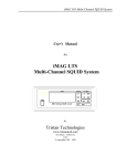
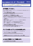
Sensor Connections
Connection to the sensors
will be made via
connectors mounted on
the back panel of the
instrument. Pins are
available for Four-wire
connections to each
sensor and the metal shell
must be connected to the
cable shield.
Figure 1 Four-Wire Sensor Connection
It is recommended that all sensors be connected using shielded, dual twisted pair cable
as shown.
Calibration Curves
Eight calibration curves for various types of sensors are built into the LTC-21.
Additionally, 16 user curves with up to 149 points each may be input via the front panel
or remote interface.
User calibration curves are stored in non-volatile RAM, and will be retained for a period
of 10 years.
1.2.1. Output Specifications
Heater Output.
The heater output provides up to 1 Ampere at 50 Volts. When using a 50Ω heater, this
corresponds to 50 Watts.
The heater output is a Constant Current Source drive and is short-circuit protected.
Output current has a resolution of 0.1%
There are four heater ranges to allow selection of a control range which closely matches
system heat capacity. They are:
•
•
•
•
Zero to 50W
Zero to 5W
Zero to 0.5W
Zero to 0.05W
The LTC-21 heater is designed to have a load of 50Ω, and it
is strongly recommended that this value of heater resistor
be used. The instrument assumes this load when displaying
the heater power range on the front panel.
NEOCERA Instrument and Systems Group
Page 5
Model LTC-21 Cryogenic Temperature Controller
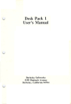
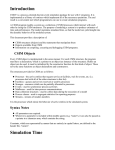
However, some users may want to use a 25Ω heater and
therefore a heater voltage switch is provided on the rear
panel of the instrument to select between 50Ω and 25Ω
heater resistors. When the 25Ω heater is selected, the
power range can be determined by dividing the displayed
range by 2. The following ranges are available in the 25Ω
mode; 0.025W, 0.25W, 2.5W, 25W.
Figure 2 Heater Connection
Connection to the heater channel is provided by a 9-pin high-power connector mounted
on the back panel of the instrument. Pins provide power, power return, and a shield
ground.
Set-Point Resolution
Setpoints in the LTC-21 are maintained as 32-bit floating point numbers, ensuring at
least six digit resolution.
Heater Feedback Type
The heater control algorithm is an enhanced digital PID type. The sample rate of the loop
is 16 Hz so that sample rate aliasing is prevented. Enhancements to the standard PID
control are:
• Loop
output is converted into units of power, unlike most PID loops which output in
volts or amperes. Therefore, the loop is linear with respect to the process variable,
ensuring faster settling and better regulation. This is very important in cryogenic
systems where the thermal load varies significantly with changes in temperature.
• Sensor
inputs are converted to temperature first then used to update the control loop.
Therefore, the gain of the loop is a constant and is independent from any non-linear
characteristics of the sensor.
• Integrator
“wind-up correction” is implemented so that rapid convergence is attained
even with large changes in setpoint.
• To
ensure accuracy, all computations are performed in IEEE-751 32-bit floating
point. Output to the heater is done using a 16 bit DAC for 1 part in 65,000
Page 6
NEOCERA Instrument and Systems Group
Model LTC-21 Cryogenic Temperature Controller
resolution. All loop variables, including the set-point, are also in 32-bit floating
point.
• High
frequency damping is performed on the differentiator term so that effective use
of this term can be allowed without instabilities caused by high frequency noise.
• Safety monitoring is
implemented so that an open or shorted connection to the input
sensor will be detected and will cause the control loop to be terminated and the
heater to be turned off.
Heater Autotune Function.
The heater control has an Autotune function wherein the instrument will 'learn' the
thermal characteristics of the system under control; then, generate appropriate PID
coefficients required to efficiently control it.
Analog Output
A low power analog output channel provided. This output can be used as a linear output
or as a second heater for temperature control of low-power systems.
Output voltage is ±12 V with a maximum current of 100mA. This is a voltage output and
over-current protection is NOT provided. Therefore, this output can be destroyed if
connected to a low resistance load that will require an excess of 100mA.
Connection to the analog output channel is made via a 4-pin connector on the back
panel. The connector housing provides a shield ground.
CAUTION
When using
output, it is
power setting
can
the analog output as a heater
important to remember that at 0
the output is not at 0 volts but
be as much as ± 100mV.
The analog output may also be used to drive a user provided
external power supply, resulting in a heater output ranging
from 30W to kWs.
Control Channel Configuration
Each output (Heater or Analog) may be assigned to either input channel independently.
Therefore, all combinations of monitoring one channel and controlling another are
allowed.
If the Heater output and the Analog output are configured for temperature control, the LTC21 will maintain two completely separate control loops.
NEOCERA Instrument and Systems Group
Page 7
Model LTC-21 Cryogenic Temperature Controller
1.2.2. Accuracy Specifications
Display
Sensor data may be displayed in units of Kelvin, Fahrenheit, Celsius, Volts or Ohms.
•
All displays are six digits plus sign, a floating decimal point and a units indicator.
•
Time averaging may be performed by operator selection of intervals between 0.5 and
16 Seconds.
Accuracy of Sensor Measurements
The accuracy of linear resistance sensor measurements, including Platinum, Carbon-Glass
etc. is 0.1% within the resistance range of 100Ω to 1KΩ , 0.25% from 1KΩ to 10KΩ and
1% between 10KΩ and 30KΩ.
The accuracy of diode sensor measurements is 0.05%.
The accuracy of sensors using the variable ac constant voltage biasing is given in the
following table:
Excitation
1mV
320uV
100uV
32uV
10uV
Accuracy
0.1%
0.1%
1%
0.1%
1%
0.5%
2%
10%
0.5%
2%
10%
Resistance Range
1 Ω to 1 MΩ
1 Ω to 500 kΩ
500 kΩ to 1 MΩ
1 Ω to 150 kΩ
150 kΩ to 1 MΩ
1 Ω to 50 kΩ
50 kΩ to 500 kΩ
500 kΩ to 1 MΩ
1 Ω to 15 kΩ
15 kΩ to 150 kΩ
150 kΩ to 1 MΩ
Table 1 Sensor Accuracy vs Sensor Excitation
All accuracy specifications are valid over the rated environmental temperature range.
Range of Temperature Measurements.
The instrument will measure and display temperatures in the range of 0K to 800K.
The actual temperature range for measurement is, of course, dependent on the type of sensor
used.
Temperature Resolution
The temperature resolution of the LTC-21 is 1 part in 512000.
Page 8
NEOCERA Instrument and Systems Group
Model LTC-21 Cryogenic Temperature Controller
Maximum Frequency of Temperature Variation
The maximum frequency component of temperature variation that the LTC-21 can process is
5Hz.
1.2.3. Relay and Alarm Outputs
Relay Outputs
The LTC-21 has two relay outputs; one for each input channel. Both normally-open and
normally-closed contacts are available on the rear panel.
The user may set the relays to open or close under specified conditions such as over or under
temperature conditions.
Contacts are rated at 0.5A, 30Vrms or 60VDC.
Audible Alarm
The LTC-21 has an audible alarm that may be configured by the user to sound on over and
under temperature conditions on either input channel.
1.2.4. Remote Interfaces
IEEE-488 and RS-232 interfaces are both standard. All functions and read-outs available
from the instrument may be completely controlled by either of the interfaces.
IEEE-488 Interface
The IEEE-488 interface allows complete remote control of the instrument as well as the
ability to read all temperature information to full internal accuracy.
The interface is compliant with IEEE Standard 488-1978.
RS-232 Interface
The RS-232 interface allows full operation of the instrument, as does the IEEE-488 interface.
The baud rate is selected by the front panel.
1.2.5. Mechanical, Form Factors
Front Panel
The front panel, including the display area is sealed membrane-type panel with the following
characteristics:
•
•
•
Large Vulcanized silicon-rubber tactile keypad.
Super-Twist LCD display with LED type dc backlight.
Power Switch (Rocker Switch).
NEOCERA Instrument and Systems Group
Page 9
Model LTC-21 Cryogenic Temperature Controller
Back Panel
The back panel interfaces are listed below:
•
•
•
•
•
•
•
•
IEEE-488 Interface connector.
Heater Output connector. Circular, AMP, 7-pin.
50Ω/25Ω Heater Selector Switch .
Two Sensor Input Connectors, Circular Lemo, 4-pin.
Analog Output Connector, AMP, 4-pin.
RS-232 Connector, DB-9.
Relay output connector. Circular, 8 pin.
ac power entry module with fuse and voltage selector.
Enclosure
The LTC-21 enclosure is a standard full-width 19 inch rack-mountable type that may be used
either stand-alone or incorporated in an instrument rack.
Bail
An instrument bail is provided standard.
Size
Enclosure size is 432mm wide x 89mm high x 337mm deep (17”x3.5”x13.25”).
Rack Mount Use
The Rack mounting accessory package contains two front panel angle brackets that can
be used to attach the instrument into a rack.
Weight
The LTC-21 weighs 7.1Kg.
1.2.6. Power
ac Power Requirements
The instrument will require single-phase ac power of 50 to 60 Hz. Voltages are selectable at
the power entry module for 100/120 or 220/ 240 Vac (tolerance ± 10%).
Power requirement is 126VA.
A low power cordset meeting the following minimum specifications is required for system
operation.
North America: Low power (10A max), single phase, NEMA terminations, UL,CSA
approvals.
EC countries: Low power (10A max), single phase, IEC-320 terminations, VDE
approval.
Instrument Fusing
A user-replaceable 5x20mm fuse is mounted in the power entry module. This module also
includes a spare.
Page 10
NEOCERA Instrument and Systems Group
Model LTC-21 Cryogenic Temperature Controller
A 5 x 20 mm 4 Amp normal blow fuse is required for 100 and 120 Vac configurations and a 5
x 20 mm IEC 127 1.6 Amp time lag fuse is required for 220 and 240 Vac configurations.
Power Grounding Requirements
The Ground wire on the ac line cord must be connected to a safety ground that does not
normally carry electrical current. This safety ground becomes the Chassis Ground of the
instrument and is used as the ground point for all cable shields. Thus, it is important to ensure
a good quality connection.
1.2.7. Environmental
Maximum Safe Ambient Temperature Range
The Temperature Controller is designed to operate over an ambient temperature range of 0oC
to 55oC without damage to the instrument. Depending on the sensor type and bias method
used, accuracy specifications are only guaranteed over a more limited range as described in
the following section.
Accuracy Ambient Temperature Range
The accuracy specifications for the LTC-21 are guaranteed over the following temperature
range: 25o C ±5o C.
Humidity/Altitude
A normal laboratory environment is expected. Proper operation over extremes of altitude or
humidity is not guaranteed.
WARNING:
To prevent shock and fire hazards, as well as damage to the
LTC-21, it should not be allowed to get wet or operate in a
condensing atmosphere.
NEOCERA Instrument and Systems Group
Page 11
Model LTC-21 Cryogenic Temperature Controller
Page 12
NEOCERA Instrument and Systems Group
Chapter 2
Installation and Setup
2. Installation
2.1. Unpacking And Inspection
Prior to unpacking the LTC-21, you should check the carton for any shipping damage. If
damage is observed, notify the carrier immediately to allow for a possible insurance claim.
The following items are included with the LTC-21. If any items are missing, notify your
NEOCERA representative immediately.
Packing List:
•
•
•
•
•
•
•
•
•
•
LTC-21 Temperature Controller
Fuses installed in the controller Power Entry Module
ac Power Cord
Users Manual
Analog Output Connector Assembly
Sensor Cable with mating connector, 5 meters
Heater Connector Assembly
Relay Connector Assembly
CE Declaration of Conformance.
CE Kit and Instructions.
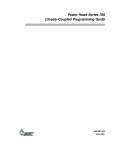
2.2. Rear Panel Layout
The rear panel layout of the LTC-21 provides connections for
the following functions:
•
•
•
•
•
•
•
IEEE-488 Interface connector.
Heater Output connector. Circular, AMP, 7-pin.
Two Sensor Input Connectors, Circular Lemo, 4-pin.
Analog Output Connector, AMP, 4-pin.
RS-232 Connector, DB-9.
Relay output connector. Circular, 8 pin.
ac power entry module with fuse and voltage selector.
NEOCERA Instrument and Systems Group
Page 13
Model LTC-21 Cryogenic Temperature Controller
Figure 3 LTC-21 Rear Panel
2.3. Power Requirements
ac power can be provided to the LTC-21 at voltages of 100/120
or 220/240 Volts, 50 or 60Hz. These MUST be selected by the
voltage selector which is part of the ac power entry module
mounted on the rear panel of the instrument.
To change the power configuration perform the following steps:
a) Disconnect the ac power cord from the instrument.
b) Locate the ac input module on the rear panel. The ac
power configuration can be seen in a small window in
the fuse drawer.
c)
Push on the small locking tab on the fuse drawer and
remove the fuse drawer.
d) To change the ac input configuration, remove the
switch block from the rear of the fuse drawer. Rotate
the switch block until the desired ac input appears in
the window of the fuse drawer.
e) Install the fuse drawer into the ac input module and
connect the ac power cord.
The LTC-21 will operate properly from either 50 or 60Hz ac power.
Page 14
NEOCERA Instrument and Systems Group
Model LTC-21 Cryogenic Temperature Controller
WARNING:
Never attempt to operate the LTC-21 at a different input line
voltage than is shown on the power input module on the rear
panel. Serious injury or equipment damage may result.
2.3.1. Fuse
The instrument fuse is located in the ac power entry module which is mounted on the rear
panel of the instrument. This module also contains a spare fuse.
The LTC-21 requires the following fuses depending on the line voltage used:
ac Power
100 - 120 Vac
220- 240 Vac
Fuse
3 Amp normal blow
1.6 Amp time lag
Table 2 ac Fusing
WARNING:
Always replace the fuse with the correct value to prevent shock
and fire hazards, as well as damage to the LTC-21.
2.3.2. Grounding And Shielding
The LTC-21 is equipped with a three-conductor power cord that connects the instrument
chassis to earth ground.
WARNING:
TO PREVENT SHOCK AND FIRE HAZARDS, ALWAYS CONNECT
THE POWER CORD TO A THREE-CONDUCTOR, GROUNDED
RECEPTACLE.
Grounding and shielding of sensor and output lines are important considerations when using
a low-noise instrument such as the LTC-21. The sensor inputs, the heater output and the
analog output are all isolated from earth ground and are connected at one point to circuit
ground inside the LTC-21.
2.4. Heater Connection
2.4.1. Heater Wiring
The Heater output is available on the rear panel at the labeled connector.
NEOCERA Instrument and Systems Group
Page 15
Model LTC-21 Cryogenic Temperature Controller
Connect your heater leads to the mating connector supplied. Care should be taken not to
ground either heater lead. If this is not possible, ground the lead connected to pin 2.
WARNING:
WITH PROPER VENTILATION, THE LTC-21 IS DESIGNED TO
OPERATE INDEFINITELY WITHOUT DAMAGE TO ITSELF IF ITS
HEATER OUTPUT IS SHORT CIRCUITED. HOWEVER, CARE
SHOULD BE TAKEN TO AVOID THIS CONDITION SINCE THE 50
WATT OUTPUT COULD DAMAGE OTHER COMPONENTS OR
RESULT IN A FIRE HAZARD.
The wire size required in your cryostat depends on the maximum power that will be required.
If 50 Watt power will be required, use 24 gauge, or heavier, stranded copper wires. Connect
the heater to the positive (+) and negative (-) outputs. The earth ground should only be used
for shielding.
Best performance will be achieved if the heater wires are run as twisted pairs which are
physically separated from the sensor leads. Heater leads should never be connected to the
sensor grounds.
2.4.2. Heater Selection.
The Heater output is driven by a current source with maximum capability of 1 Amp. This
output is calibrated for use with a 50Ω heater which also allows the maximum output power
of 50 Watts. Although the exact heater resistance is not critical, the use of a nominal 50Ω
heater is strongly recommended. The LTC-21 will work with other heater resistances, but the
output will no longer be calibrated. If a resistance other than 50Ω is used, the actual power
may be calculated from the power indicated on the front panel using the following equation:
Actual Power = Indicated Power * (Heater Resistance) / 50
The voltage compliance of the current source is limited to about 50 volts. For this reason,
full-scale linear operation is only possible under the following conditions:
Range
50 Watt
5 Watt
0.5 Watt
0.05 Watt
Maximum Heater
Resistance
50Ω
160Ω
500Ω
1.6KΩ
Table 3 Conditions for Linear Operation of Heater
Use of a heater resistance value less than 50Ω provides linear operation under all conditions,
but the output power is always less than indicated. For systems that require heater power
substantially less 50 mWatt, it is possible to use a current divider having a 50Ω resistor at
room temperature connected in parallel with a higher resistance heater attached to the system.
Page 16
NEOCERA Instrument and Systems Group
Model LTC-21 Cryogenic Temperature Controller
Some users may want to use a 25Ω heater and therefore a heater
voltage switch is provided on the rear panel of the instrument
to select between 50Ω and 25Ω heater resistors. When the 25Ω
heater is selected, the power range can be determined by
dividing the displayed range by 2. The following ranges are
available in the 25Ω mode; 0.025W, 0.25W, 2.5W, 25W.
2.4.3. Analog Output Connection
The Analog output port can be software-configured as either a 1 W (max) output for
temperature regulation or as a calibrated analog output for monitoring temperature. The
hardware connection is the same in either case.
The ground connection should only be used for shielded leads. The low side of this output
may be grounded when using it to monitor temperature, but a differential measurement is
usually preferred to avoid adding noise to the measurement. The low side should not be
grounded when using the Analog output for temperature regulation. If this can not be
avoided, it is essential that the low side be grounded at one point only and that it not be
connected in common with the sensors.
The type of wire used to connect to the Analog output is usually not critical. Shielded,
twisted, 24 gauge copper wire is commonly used inside the cryostat, but the exact choice
depends on thermal requirements and electrical noise in your cryostat.
2.5. Sensor Connection
Sensors can be attached to the two labeled Sensor input connectors on the rear panel. A
mating connector (Lemo Inc. FGG.1B.304.CNAD52) with attached shielded cable is
supplied for use in attaching your sensor.
The LTC-21 is designed to make accurate readings, even in the presence of large interfering
signals, such as power-line pick up. Nevertheless, it is always best to use properly designed
input leads to minimize stray pick up. The sensor cable supplied with the LTC-21 has been
carefully selected for low-noise operation. It comprises two, twisted pair cables inside a noncurrent carrying shield. If it is necessary to replace this cable, always use a cable of similar
design. Additional or replacement connectors with attached cable are available from
NEOCERA Instrument and Systems Group.
Wiring diagrams for various sensor types are shown in Appendix C. For best performance,
all sensors should be connected in a four-terminal configuration. Polarity is critical with
diode sensors, but generally unimportant with all other types. All four connections should be
floating, but if it is necessary to ground any part of the sensor circuit, it must be the low (-)
side. The ground connection should only be used for the sensor cable shield. The cable
shield should be grounded at the connector. It is generally best NOT to ground the shield at
the cryostat.
Optimum wire selection for use inside your cryostat depends on many factors. In all cases, it
is best to make a four-wire connection using two sets of shielded, twisted pairs. The shield
NEOCERA Instrument and Systems Group
Page 17
Model LTC-21 Cryogenic Temperature Controller
should not be connected to the low side of the sensor leads. The shield ground should be
attached to the sensor connector at the rear panel of the instrument. Special wire is available
for sensor connection from a number of sources. In most cases, it is adequate to run two pair
of twisted, 0.005" diameter leads inside your cryostat. Common choices of metal for these
leads include phosphor-bronze, brass, and Manganin. Very high resistance leads (greater
than 100 ohm per wire) should be avoided if possible. Low resistance (copper) leads work
well so long as they do not conduct so much heat into the sensor as to cause erroneous
readings.
After the sensor is connected, it is essential that the LTC-21 software be correctly configured
for use with the installed sensor type.
2.6. Relay Connection
Each relay contact is rated at 0.5A, 30Vrms or 60VDC.
The relay contacts will change state on all relays which are enabled if the temperature
exceeds the assigned high or low limits.
2.7. Interface Connection
Connection to the IEEE-488 is via an industry standard IEEE-488 connector to the IEEE-488
connector on the rear panel.
Connection to the RS-232 is via a female DB-9 connector to the RS-232 connector on the
rear panel.
2.8. Mounting The LTC-21
Bench Mounting
The LTC-21 is supplied ready for bench use. Plastic feet are supplied on the bottom of the
instrument; these should not be removed as they allow for an air gap beneath the instrument
which aids in cooling. The front of the instrument may be elevated for better viewing angle
using the built-in tilt stand.
Rack Mounting
The LTC-21 may be rack mounted using the optional rack-mount kit available from
NEOCERA Instrument and Systems Group. Simply attach the supplied ears
to the sides of the LTC-21. The LTC-21 may then be mounted in any standard
19" rack-mount enclosure.
Page 18
NEOCERA Instrument and Systems Group
Chapter 3
Operation
3. Operation
3.1. Use of the Keyboard
All keys on the LTC-21 are programmed to provide a consistent result, regardless of the
menu displayed.
Response of the LTC-21 to the various keys is summarized in the following sections.
3.2. LOCAL Key
Pressing the LOCAL key unconditionally terminates remote control of the LTC-21 via either
the RS-232 or IEEE-488 port. This permits control via the front panel keys. The REMOTE
indicator LED turns off to indicate this condition. All keys, other than the LOCAL key, are
disabled if the REMOTE indicator LED is on.
3.3. FUNCTION Keys
3.3.1. CONTROL
Regardless of the menu currently displayed, pressing CONTROL causes the LTC-21 to enter
the CONTROL mode and show the Normal Operating Display. Temperature regulation will
begin immediately (or continue) if the LTC-21 is properly configured for
temperature control.
3.3.2. MONITOR
Regardless of the menu currently displayed, pressing MONITOR causes the LTC-21 to enter
the MONITOR mode and show the Normal Operating Display. Heater outputs are
immediately and unconditionally disabled.
3.3.3. SETUP
Pressing SETUP calls up the MAIN SETUP MENU used to change the LTC-21 operating
parameters. If the LTC-21 was previously in the CONTROL mode, it will continue to
regulate temperature until a parameter is changed which effects one of
the operating parameters of the control loop.
3.4. DATA ENTRY Keys
Entering data from the front panel is a straightforward process using the following keys:
3.4.1. Cursor Keys
The four, arrow-shaped cursor keys are used to make menu selections by moving the cursor
(indicated by flashing text) around the display.
3.4.2. INC (Increment) and DEC (Decrement) Keys
The two keys labeled INC and DEC are used to scroll through the possible choices for a
given item that has been selected using the cursor keys. The choices presented are usually
NEOCERA Instrument and Systems Group
Page 19
Model LTC-21 Cryogenic Temperature Controller
limited to those that are valid and the operator is warned of an invalid entry by the internal
beeper. However, in some cases where items on different menus are interrelated, invalid
choices may be allowed to simplify data entry by not forcing a particular sequence of entries.
For this reason, it is a good idea to verify all instrument settings after a change has been made
to any one of them.
3.4.3. Numeric Keypad
The 12 keys on the numeric keypad are only used when a numeric entry is required. If a
numeric entry is not appropriate, these keys are automatically disabled.
3.4.4. BACKSPACE
The BACKSPACE key erases the last character entered from the numeric keypad.
3.4.5. CLEAR
The CLEAR key erases the entire entry from the numeric keypad and allows you to start over.
3.4.6. ENTER
The ENTER key is used to terminate the entry of data from the keypad. If you EXIT a menu
without pressing ENTER, the previous data is restored and the new entry is lost.
3.4.7. EXIT
The EXIT key will unconditionally move you back up one menu (see Section 3.6, The Menu
Tree). Pressing EXIT does not cause an implied ENTER, i.e. if data has been input but
ENTER has not been pressed, it may be lost when EXIT is pressed.
3.5. Special Key Assignments
Occasionally, a key will be assigned a special usage other than that described above. If this is
done, the display will always prompt the user and describe this special usage. For example,
the ENTER key is used in the CONTROL and MONITOR modes to allow entry of a new
temperature setpoint.
Page 20
NEOCERA Instrument and Systems Group
Model LTC-21 Cryogenic Temperature Controller
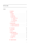
3.6. Menu Tree
LTC-21 functions are represented by the following menus.
Monitor Mode Screen
Power Up Screen
Setpoint Screen
Control Mode Screen
Display Units
Display Update Rate
Display Configuration
Setup Screen
Configure Datalog
Display Datalog
Sensor Configuration
PID Mode
Table Mode
Output Configuration
Auto PID Mode
Ramp
Alarm & Relay Setup
Misc Menu
Remote I/O Configuration
Sensor Calibration Table
Figure 4 Menu Tree
NEOCERA Instrument and Systems Group
Page 21
Model LTC-21 Cryogenic Temperature Controller
Page 22
NEOCERA Instrument and Systems Group
Chapter 4
Initial Power Up
4. Initial Power Up Sequence And Display
When the LTC-21 is first powered up, it goes through a series of internal self-tests, then
performs an internal ADC calibration. This is indicated by the display of "ADC Cal" (A/D
Converter Calibration) in place of the measured temperature.
Sensor #1
Sensor #2
ADC Cal
ADC Cal
Set
Point
Heater Off
Push ENTER to Change SET POINT
Figure 5 ADC Calibration Screen
After the calibration is complete, the LTC-21 enters the MONITOR mode and "ADC Cal" is
replaced by the measured sensor value. This process requires approximately five seconds.
First Time Operation
As shipped from the factory, the LTC-21 is software configured to read and display the
resistance (in Ohms) of a sensor connected to SENSOR #1 input. The interface is configured
as an IEEE-488 port with address 15. SENSOR #2, the heater, analog output, relays and
alarms are all disabled.
NOTE:
The LTC-21 performs an internal calibration
on each sensor channel on power-up. To insure
highest performance and accurate temperature readings, a
temperature sensor must be attached to the SENSOR input
channel you wish to monitor prior to power-up.
NEOCERA Instrument and Systems Group
Page 23
Model LTC-21 Cryogenic Temperature Controller
Page 24
NEOCERA Instrument and Systems Group
Chapter 5
Operating Modes
5. Operating Modes
5.1. Introduction To The Three Operating Modes
The LTC-21 has three distinct operating modes; the CONTROL, MONITOR and SETUP
modes. These are accessed using the buttons in the FUNCTION section of the front panel. If
the LTC-21 is in the LOCAL mode (REMOTE indicator LED turned off), pressing any of
these buttons will immediately put the LTC-21 into the indicated operating mode, regardless
of its current status.
MONITOR
The monitor mode is used to monitor and display the temperature of
calibrated sensors connected to the inputs. Uncalibrated sensors
(and calibrated sensor, if desired), are displayed in their intrinsic
units, i.e. Volts, Ohms, etc. Heaters are unconditionally disabled in
this mode.
CONTROL The control mode is used when temperature regulation is desired.
Heaters are enabled in this mode which is otherwise identical to
MONITOR mode.
SETUP
The setup mode is used to change any of the LTC-21 parameters
with the exception of temperature SET POINT. If SETUP mode is
selected from CONTROL mode, the LTC-21 will continue to
regulate temperature unless a parameter is changed
which effects one of the operating parameters
of the control loop.
5.2. Monitor Mode: Monitoring Temperature With The LTC-21
5.2.1. Using the Monitor Mode.
The MONITOR mode is used to monitor the temperature of the sensors. The Heater output
is disabled in this mode, so temperature regulation is not possible. The Analog output is also
disabled if it is configured for controlling temperature ; if it is configured as a Monitor port, it
will continue to function normally.
NEOCERA Instrument and Systems Group
Page 25
Model LTC-21 Cryogenic Temperature Controller
Sensor #1
Sensor #2
350.00K
-263.85C
Set
Point
Heater Off
Push ENTER to Change SET POINT
Figure 6 Monitor Mode Screen
Usually, the Normal Operating Display, will be presented in the MONITOR mode. The
output of the sensors are displayed in large characters under the assigned SENSOR# (input
number). If no sensor type has been assigned to an input, the display will be blank under the
unassigned SENSOR#. If there is no sensor attached to the connector on the rear panel of
the instrument, or if the sensor calibration has not been stored in the LTC-21, that channel
may display “. . . . K” or an erroneous reading. If no sensor is connected, please select “No
Sensor” in the Sensor Configuration Menu (refer to Section 5.4.6).
5.2.2. Changing the SET POINT
The temperature SET POINT row of the Normal Operating Display will not be shown in the
MONITOR mode since the heaters are disabled. Nevertheless, it is possible to change the
stored SET POINT for both sensors by pressing ENTER to bring up the HEATER
SETPOINT SELECTION display.
The Heater Set Point Display is a multi-functional display, showing most of the information
regarding temperature control. The Heater and Analog set points are displayed in the center
column of the screen. The actual temperature of the sensor assigned to the particular heater is
displayed just to the right of the setpoints.
Below the heater information, the heater mode selection (PID, Auto PID, etc.) and actual
heater power ( % of range) is displayed.
The bottom of the screen displays the P, I, D, and PO values in effect for the Heater and
Analog set points.
Page 26
NEOCERA Instrument and Systems Group
Model LTC-21 Cryogenic Temperature Controller
Heater Set Point Selection
Heater Set Point
325.00K
305.000K
Analog Set Point
315.00K
300.000K
AUTO PID
46% of 0.5 W
Heater P= 50 I= 25 D= 6 P0= 0.0
Analog GAIN = 1.00
OFFSET = 1.00
Press EXIT to return
Figure 7 Setpoint Screen
To change to SETPOINT, move the cursor to the desired SETPOINT and use the numeric
keypad to enter new values. Press ENTER to confirm the new entries. Press EXIT to return
to the Main Operating Display. The new SET POINT will take effect when the CONTROL
mode button is pressed.
5.2.3. Relays and Alarms in Monitor Mode
Relays and Alarms remain active in the MONITOR mode. To enable/disable them or to
change their high/low limits, press the SET UP key and follow the directions given in Section
5.4.9. When this is done, the SETUP mode indicator LED will turn on. Note that the
MONITOR mode indicator LED remains lit while you do this indicating that the LTC-21 is
still in the MONITOR mode with Relays, Alarms, and the Monitor function of the Analog
output still active.
The LTC-21 will leave the MONITOR mode if some critical configuration parameters, such
as sensor type, are changed. In this case, the MONITOR indicator LED will turn off; relays,
alarms, and analog output will be disabled.
5.2.3.1. Control Mode: Regulating Temperature With The LTC-21
The CONTROL mode regulates temperature and is identical to the MONITOR mode with the
following exceptions:
•
Heater output is enabled.
•
Analog output is enabled (regardless of its configuration).
NEOCERA Instrument and Systems Group
Page 27
Model LTC-21 Cryogenic Temperature Controller
PID
Sensor #1
348.782K
Set
Point
Sensor #2
-263.854C
350.000K
Heater 23% of 5W
Push ENTER to Change SET POINT
Figure 8 Control Mode Screen
The Normal Operating Display shows the following additional information in the CONTROL
mode:
•
The Heater MODE is displayed in the upper left-hand corner.
•
The Heater power, as a percent of full scale, and the full scale range (i.e. "MAX
PWR") are shown near the bottom of the display.
•
The SET POINTs are displayed for any output that is currently active.
If a stored SET POINT value is not shown on the Normal Operating Display, the LTC-21 is
not correctly configured to regulate temperature at this set point. You should check all of the
following:
•
The CONTROL indicator LED must be on (press CONTROL).
•
A SENSOR # must be assigned to the output
•
MAX PWR range must be a value other than "OFF" (the MAX PWR range is shown
after HEATER % on the Main Operating Display).
• A Heater is connected to the HEATER OUTPUT (must not be
open).
Changing SET POINT, or any other instrument parameter, is done as in the MONITOR
mode. Most parameters can be changed without affecting temperature regulation. However,
the LTC-21 will automatically terminate the CONTROL mode, disabling all heaters, if a
parameter is changed that effects one of the operating
parameters of the control loop. Changing the sensor assignment or the heater
range are examples of such a change. If CONTROL mode is terminated, the CONTROL
indicator LED will turn off.
5.3. Setup Mode: Configuring The LTC-21
5.3.1. Introduction To The Setup Mode
SETUP mode is used to configure all of the LTC-21's operating parameters, with the
exception of temperature SET POINT (which is selected from either the MONITOR or
Page 28
NEOCERA Instrument and Systems Group
Model LTC-21 Cryogenic Temperature Controller
CONTROL mode by pressing ENTER). To enter the SETUP mode and display the
INSTRUMENT SETUP SELECTION menu, simply press the front panel SETUP button.
The SETUP mode indicator LED will turn on indicating that the LTC-21 is in the SETUP
mode.
The LTC-21 will continue to regulate temperature if you enter the SETUP mode from the
CONTROL mode. It will terminate CONTROL only if a setting is changed which makes
regulation impossible or which effects one of the operating
parameters of the control loop. For example, you may enter the SETUP mode
to change display units without affecting temperature regulation. However, if you change the
type of sensor assigned to the input, the LTC-21 will turn off the heater. The CONTROL
mode indicator LED will turn off, indicating that you are no longer regulating temperature.
5.3.2. Instrument Setup Selection Menu
The INSTRUMENT SETUP SELECTION menu is displayed whenever the SETUP button is
depressed.
INSTRUMENT SETUP SELECTION
Display
Sensors
Outputs
Misc
Press ENTER to select function
Press EXIT to return
Figure 9 Setup Screen
The four selections shown on this menu (DISPLAY, SENSORS, OUTPUTS, MISC) call up
submenus which can be used to change any of the LTC-21 operating parameters. Use the
right and left cursor keys to highlight the desired choice, indicated by a flashing selection on
the display, and press ENTER.
When first configuring the LTC-21, it is a good idea to go through all selections from left to
right on this menu to display, select, and verify all the possible choices.
NEOCERA Instrument and Systems Group
Page 29
Model LTC-21 Cryogenic Temperature Controller
5.3.3. Display Configuration Menu
Choosing DISPLAY from the INSTRUMENT SETUP SELECTION Menu calls up the
DISPLAY CONFIGURATION menu.
DISPLAY CONFIGURATION
SETUP DISPLAY UNITS
SETUP INPUT FILTER
SETUP DATA LOG
DISPLAY DATA LOG
Select and Press ENTER to Change Item
EXIT to Quit
Figure 10 Display Configuration Screen
5.3.4. Set Display Units Menu
Choosing SETUP DISPLAY UNITS from the DISPLAY CONFIGURATION Menu calls up
the SETUP DISPLAY UNITS menu. Use the cursor keys to choose the desired SENSOR #
and then select the desired units using the INC and DEC keys. Return to any operating mode
by pressing the appropriate front panel button or return to the INSTRUMENT SETUP
SELECTION menu using EXIT.
SET DISPLAY UNITS
SENSOR
UNITS
#1
Kelvin
#2
Celsius
Figure 11 Display Units Screen
Note that it is possible to select units that are not appropriate for the currently assigned
sensor, e.g., Ohms can be selected for diode sensors and Kelvin can be selected for
uncalibrated sensors (This is done to simplify entry of data for new sensors). It is left to the
operator to assure that the selected units are appropriate for the sensor.
The Effects of Changing Display Units
Changing display units has a global effect on all displays. For example, if SENSOR #1 is
displayed in Kelvin, the set points for all relays assigned to this sensor will be displayed in
Kelvin.
Changing display units between different temperature units only affects the display; it has no
effect on the operation of the LTC-21. However, if you change from temperature units
(Kelvin, Fahrenheit, or Celsius) to fundamental sensor units (ohms or volts), the unit will
Page 30
NEOCERA Instrument and Systems Group
Model LTC-21 Cryogenic Temperature Controller
leave the CONTROL mode. Changing between fundamental units or from fundamental to
temperature units has the same effect. This happens because the LTC-21 regulates
temperature using the displayed units to determine the error signal (i.e., If ohms are
displayed, the regulation is based on the difference in ohms between the measured sensor
resistance and the set point. If temperature units are displayed, the LTC-21 calculates the
error signal in Kelvin). This is done to provide a much more linear system response when
using nonlinear sensors.
Input Filter Time Constant Menu
From the DISPLAY CONFIGURATION Menu, the user may enter the SETUP INPUT
FILTER TIME CONSTANT menu. Use the INC and DEC key to change the input filter
time constant of 0.5sec, 1 sec, 2 sec, 4 sec, 8 sec, and 16 seconds.
UPDATE INPUT FILTER TIME CONSTANT
INPUT FILTER TIME : 0.5 Seconds
EXIT to Quit
Figure 12 Display Update Rate Screen
Displayed temperature data is refreshed every 0.5 seconds regardless of the Input Filter Time
setting. Further, the input sensors are always sampled 16 times per second. The data
displayed will be averaged over the period of Input Filter Time Constant. e.g. For an Input
Filter Time of 0.5 second, the controller will be displaying the average of 8 input samples. In
effect, this process filters out input signal noise by continuously averaging data over the
selected time period, and updates the display and PID control algorithm with this filtered
data.
The Remote interface uses the SDUR and QDUR? commands to set the Input Filter Time.
Since the Input Filter Time affects the PID control loop, correct selection of this value is
necessary to ensure optimum PID control. Specifically:
•
Selection of a short Input Filter Time may result in noisy control. This is especially
true in systems that use aggressive Derivative terms since the derivative is most
affected by both signal noise and input sample rate. The result may be reduced
control accuracy near the set point and will be most obvious in systems where there
are high noise levels (such as a Cryocooler).
NEOCERA Instrument and Systems Group
Page 31
Model LTC-21 Cryogenic Temperature Controller
•
Selection of a long Input Filter Time will slow the responsiveness of the controller
and may result in low level oscillations around the set point. This effect is identical
to the selection of an Integrator time that is too long for the system being controlled.
For optimum PID control, the best value for the Input Filter Time is about one tenth of the
Integrator time. This will provide the maximum noise rejection while still ensuring
responsiveness and control stability. Smaller values may be used with relatively quiet
systems, or systems where the Derivative term is not used. Larger values of Input Filter Time
are not recommended.
5.3.5. Datalog
Refer to Chapter 8 for a discussion of the Datalog feature.
5.3.6. Sensor Configuration Menu
Choosing SENSORS from the INSTRUMENT SETUP SELECTION menu calls up the
SENSOR CONFIGURATION menu used to specify the sensors connected to the inputs.
SENSOR CONFIGURATION
SENSOR#1
SENSOR#2
DESCRIPTION
LS DIODE #10
PT 100/392
Press EXIT to quit
Figure 13 Sensor Configuration Screen
Use the cursor keys to move to the desired SENSOR# which refers to the SENSOR (INPUT)
# labeled on the rear panel. Select the sensor type connected to this input using the INC
(increment) and DEC (decrement) keys. The types of sensors presented may vary from
instrument to instrument depending on configuration.
Page 32
NEOCERA Instrument and Systems Group
Model LTC-21 Cryogenic Temperature Controller
The Model LTC-21 will present the following choices for sensors in the Sensors Menu :
SENSOR TYPE
LS DIODE #10
CryoCal D3
SI-410NN
LS TG-120
PT 100/385
PT 1000/385
PT 100/392
PT 1000/392
CAL Resistors
USER TABLES HERE
DESCRIPTION
LakeShore Si Diode, Std. Curve #10
CryoCal Si Diode, Std. Curve D3
Scientific Inst Si Diode
LakeShore GaAlAs Diode, Std. Curve
100Ω Platinum, European Std. (385Ω at 100°C) dc
1000Ω Platinum, European Std. (385Ω at 100°C) dc
100Ω Platinum, American Std. (392Ω at 100°C) dc
1000Ω Platinum, American Std. (392Ω at 100°C) dc
For Calibration Purposes Use
Any user specified sensor
Table 4 LTC-21 Supported Sensors
When you select a new sensor, the LTC-21 will always leave the Control mode to prevent
dangerous operating conditions. After selecting the desired sensor, press EXIT, MONITOR,
or CONTROL to enter the sensor and exit the display.
5.3.7. Output Configuration Menu
Introduction to Configuring the Outputs
Choosing OUTPUTS from the INSTRUMENT SETUP SELECTION menu displays the
OUTPUT CONFIGURATION menu used to assign and configure the HEATER and
ANALOG outputs.
OUTPUT CONFIGURATION
OUTPUT SENSOR MODE MAX PWR
HEATER
#1
PID
5W
ANALOG NONE Monitor Ramp
HEATER P= 150 I= 25
D= 6 P0= 0.0
ANALOG GAIN= 1.00
OFFSET= 375.000K
Figure 14 Output Configuration Screen
NEOCERA Instrument and Systems Group
Page 33
Model LTC-21 Cryogenic Temperature Controller
As usual, use the cursor keys to select the menu field you want to change and the INC and
DEC keys to scroll through the choices for that field. The options available are summarized
below:
MENU FIELD
SENSOR
MODE
MAX PWR
CHOICES
#1
#2
NONE
AUTO P
AUTO PI
AUTO PID
PID
Table
Default
Monitor
OFF
0.05 W
0.5 W
5W
50 W
PURPOSE
Assigns the selected OUTPUT to SENSOR #1
Assigns the selected OUTPUT to SENSOR #2
Disables the selected OUTPUT
AutoTuned; Proportional gain only
AutoTuned; Proportional and integral gain
AutoTuned; Full PID settings
Manually selected PID coefficients
PID coefficients selected from stored data
Factory default PID coefficients
Analog output used for temperature monitor
Turns off the Heater
Sets Maximum Output Power = 0.05 Watt
Sets Maximum Output Power = 0.5 Watt
Sets Maximum Output Power = 5 Watt
Sets Maximum Output Power = 50 Watt
Table 5 Output Configuration Options
SENSOR Menu Field
This field assigns the outputs to a particular SENSOR# (input). The possible choices are: #1,
#2, and NONE. Either output may be assigned to either sensor. Note that both outputs may
be assigned to the same input. This may be used, for example, to regulate temperature using
the HEATER output while monitoring small fluctuations using the ANALOG output. It is
not possible (or reasonable) to assign both inputs to the same output.
MODE Menu Field
This field determines the method used to calculate the output power/current. There are five
basic methods (MODEs) used; Auto PID, PID, Table, Default and Monitor. The MODE
assigned to the heater is always displayed in the upper left hand corner of the Main Operating
Display while the instrument is in CONTROL MODE.
PID Mode - The PID mode provides direct operator control of all PID coefficients.
Correct selection of these terms is often difficult for cryogenic systems and may
require substantial trial-and-error adjustment by the operator. Chapter 6 provides
useful information which may help in selecting these values.
Page 34
NEOCERA Instrument and Systems Group
Model LTC-21 Cryogenic Temperature Controller
If the PID mode is selected, the screen will display the currently used values for P, I,
D, and P∅.
OUTPUT PARAMETERS
HEATER
ANALOG
P= 150
P=
50
I= 25Sec.
I= 10Sec.
D=
6Sec.
D=
0Sec.
P0= 0.00%
P0= 0.00%
Pwr Limit = 35%
Gain= 1.00
Offset= 325.00
Figure 15 PID Mode Screen
To change these values, move the cursor to the desired field, enter the new value from
the numeric keypad, and press ENTER. Exit from this menu using the EXIT key or
return directly to the CONTROL mode using the CONTROL key. Note that you can
change any of the PID coefficients without interrupting temperature regulation. Of
course, if the new PID coefficients entered are not appropriate, temperature regulation
may quickly deteriorate.
The P term is an arbitrary gain factor which can be chosen to have any value
between 0.1 and 1000. Typical systems will operate with a gain of 10. If the
gain is too high, the system will oscillate. If it is too low, it will be slow to
respond.
The I term is given in seconds; its reciprocal is the angular frequency at which
the integral term has gain equal to the P term. The range of allowed values is
0.1 to 10,000 seconds. The LTC-21 also recognizes I = 0 as a special case
which turns the integrator term off completely.
The purpose of the I term is to provide extremely high gain near dc. This
allows the temperature controller to regulate at the set point with negligible
input error signal. Note that to minimize the effect of the integrator, the I term
should be set to a large value, or 0 to completely turn it off. A typical
cryogenic system will work with I = 20.
The D term is also given in seconds and its reciprocal is the angular frequency
at which the D gain is equal to the P term. The range of allowed values is
from 0 to 1000 seconds. Most systems work best with D = I/4. To minimize
the effect of the D term, you should select a small value.
NEOCERA Instrument and Systems Group
Page 35
Model LTC-21 Cryogenic Temperature Controller
The P∅ term provides a fixed output power independent of sensor value. It is
given as a percent of full scale power with
0 < P∅ < 100%
and should usually be set to zero. It is most commonly used by itself (i.e. with
P = I = D = 0) in order to fix the output power at a selected level.
!
Pwr Limit - this is a safety setting for the 50W power range only. The default
setting from the factory 35%. This is equivalent to 10W for the 50W Max Power
range. If user desires to have more than 10W for the 50W range, simply increase the
P∅ term. If the P∅ term is set to < 100% , and the heater is outputting at this limit,
the heater output percentage sign will blink to signal that it has reached the preset
limit.
Auto PID Modes- The Auto PID modes are used if you want the LTC-21 to
automatically select PID coefficients. Three such modes are available; Auto PID,
Auto PI, and Auto P:
Selection
Function
Auto PID
selects a complete set of proportional (P), integral (I), and
derivative (D) coefficients.
sets the derivative term to zero.
uses only proportional gain.
Auto PI
Auto P
Table 6 PID Modes
The use of these modes is described in detail in Chapter 7.
TABLE mode - The LTC-21 provides five PID tables, each has 10 PID entries.
When the Table mode is selected, the LTC-21 will use the current temperature setting
and obtain the interpolated PID from the selected table for the specified temperature
set points.
The Table mode allows the operator to select the PID coefficients from ten sets of
values stored in each of the PID Tables. This eliminates the need to remember or
reenter coefficient sets that have been stored. This is particularly convenient for use
with systems that require very different coefficients at different temperatures. Once
good coefficients have been determined for each temperature range, these can be
stored in the table. The values can then be easily recalled from the table when
returning to this temperature range.
Page 36
NEOCERA Instrument and Systems Group
Model LTC-21 Cryogenic Temperature Controller
If the Table mode is selected, the screen will change to display the table coefficients
currently in use.
PID Table 4
P
I
D
50
20
5
70
25
7
100
15
9
120
15
6
60
10
3
Press EXIT to return
Set Pt
350.000K
200.000K
100.000K
° 20.000K
11.000K
P0
0.00
0.00
0.00
0.00
0.00
Htr Rg
50W
5W
5W
0.5W
0.05W
Figure 16 Table Mode Screen
Example:
If the current experiment temperature is 150K, the PID setting will be 80-208-0.00. (For 150K, the interpolation process takes the PID & P0s from 200K
and 100K entries, and yield the interpolated 80-20-8-0.00.) The heater range
will be the 5W range. This will change the MAX PWR setting in the output
screen if TABLE mode is selected.
To select a new Table entry for the Heater output, move the cursor to the Index field
(the number after the PID Table heading) and use the numeric keypad to enter the new
Index #. Press ENTER and then EXIT the menu in the usual way.
CAUTION:
The last Index selected before exiting the PID Table
screen will be the PID Table selected. Be sure to enter
the proper index upon exiting the table.
To change the entries in the Table, move the cursor to the desired field and enter the
desired value from the numeric keypad. Press ENTER and then EXIT the menu in the
usual way.
NEOCERA Instrument and Systems Group
Page 37
Model LTC-21 Cryogenic Temperature Controller
Default - If the Default mode is selected, the LTC-21 displays and uses the following
factory default values for PID coefficients:
P = 100
I = 10
D = 0
P0 = 0.00 %
Most systems can be regulated using these values, but the response will be far from
optimum. The values were chosen to err on the side of stability rather than speed.
Monitor - The Monitor mode is only applicable to the ANALOG Output. The LTC21 allows you to use the ANALOG output either as a low-power heater output or as a
temperature monitor port. If Monitor is selected, OUTPUT PARAMETERS of
Analog Gain and Offset are assigned to this output, rather than PID coefficients. Gain
determines the change in output voltage for a given temperature change. Offset,
given in sensor units, is used to Adjust the zero output point. For example, if a
calibrated sensor is installed and the display units are selected to be Kelvin, the
Analog Output voltage will be given by:
V = (OFFSET - Temperature in Kelvin) * GAIN
This feature is commonly used to monitor small changes in temperature on a chart
recorder.
Example for Use with a Chart Recorder
For an application with temperature for sensor 1 is in the 230K to 240K
range:
•
In the Output configuration page, set both Heater and Analog Port to
Sensor 1.
•
Set Analog Port Mode to Monitor.
•
By pressing Enter at Monitor, it shows the Output Parameters screen.
•
Select Offset to 235K, and Gain to 1.00.
•
The Chart Recorder connected to the Analog port will show its chart
reading
for 230K as
for 235K as
for 240K as
•
Page 38
+5V = (235K - 230K) * 1.00
0V = (235K - 235K) * 1.00 and
-5V = (235K - 240K) * 1.00
The Gain of 1.00 can be changed to 0.5 to get half of the scale.
NEOCERA Instrument and Systems Group
Model LTC-21 Cryogenic Temperature Controller
If anything other than "Monitor" is chosen for the Analog Output, PID coefficients
will be assigned to it in the same way that they are assigned to the Heater output. The
Analog output can then be used as a low-power temperature regulator with a
maximum output capability of 100 mW. AUTOTUNE is not available on the Analog
output.
MAX PWR Menu Field
The MAX PWR field only applies to the Heater output and is used to set its maximum output
power capability. Choices are OFF, 0.05 Watt, 0.5 Watt, 5 Watt, and 50 Watt. All of these
settings assume that a 50Ω heater is connected to the output. The LTC-21 will work with
other heater resistances, but the output power will be incorrectly displayed. Since the LTC21 is configured as a current source, the actual heater power can be calculated from the
following equation:
Actual Heater Power = (Indicated Power) * (R / 50)
This equation is valid for conditions which result in output power less than 50 Watt and
output voltage less than 50 Volt.
For the 50 Watt output, there is a built-in power limit protection in the output configuration's
PID mode setting. Please Refer to PID mode on PWR Limit setting.
Ramp Menu Field
This menu field is used to setup the Temperature Ramp
parameters and appears as shown below. The currently selected
field will appear as flashing text.
Ramp Configuration
Set Point:
Target Temperature:
Degrees Per Minute:
Channel Number:
Ramp Armed:
Heater:
290.000K
400.000K
50.000K
#1
OFF
0% of 5W
…..K
Idle
Figure 17 Ramp Configuration Menu
In order to change the setup parameters, press the cursor keys
until the desired selection is shown in flashing text. For the
Set Point, Target Temperature and the Degrees Per Minute
fields, enter a new value via the numeric keypad and press the
ENTER button. For the Channel Number and Ramp Armed fields,
simply press the INC/DEC keys.
The …..K field displays the current temperature.
NEOCERA Instrument and Systems Group
Page 39
Model LTC-21 Cryogenic Temperature Controller
To execute Ramping, the Ramp Armed field must be set to ON
and the Mode set to PID or Table (not Autotune). Enter the
Control Mode to begin the Temperature Ramp. Idle will be
replaced by Ramping in the Ramp Configuration Menu. Reaching
the Target Temperature or entering the Monitor Mode will
terminate Ramping.
5.4.8. Misc Menu
5.3.7.1. Introduction to the MISC MENU
MISC MENU
Alarm and Relay Setup
Remote I/O Config.
Sensor CAL Tables
Instrument Calibration
Select and Press ENTER to Change Item
EXIT to Quit
Figure 18 Misc Menu Screen
The MISC MENU is used for the following functions:
SELECTION
Alarm & Relay Set Points
Remote I/O Configuration
Sensor CAL Tables
Instrument Calibration
FUNCTION
Configures the Alarms & Relays
Configure IEEE-488 and RS-232 ports
Enter/Modify Sensor Calibration Tables
Recalibrates the LTC-21
Table 7 Misc Menu Selections
5.3.8. Alarm & Relay Set Points
To change the configuration of the Alarms or Relays, select the Alarm and Relay Set Point
menu item from the MISC MENU; this will display the Alarm and Relay Configuration
menu.
Page 40
NEOCERA Instrument and Systems Group
Model LTC-21 Cryogenic Temperature Controller
Alarm and Relay Configuration
Status
Alarm 1 Armed
Alarm 2 Disarmed
Relay 1 Armed
Relay 2 Disarmed
High Lim
295.000K
450.000C
290.000K
-271.000C
Low Lim
235.000K
-100.000C
200.000K
100.000C
Figure 19 Alarm & Relay Setup Screen
Use the cursor keys in the usual way to select the item you want to change.
Alarm 1 and Relay 1 (displayed in the first column of the Alarm and Relay Configuration
Menu) are always assigned to Sensor #1; Alarm 2 and Relay 2 are always assigned to Sensor
#2. The Status of the alarms and relays is displayed in the second column. Each alarm and
relay may be separately armed (enabled) or disarmed (disabled).
The High Lim and Low Lim columns of this display are used to change the set points. Move
the cursor to the limit you want to change, enter the new value with the numeric keypad, and
press ENTER. If the temperature exceeds High Lim or drops below Low Lim, the internal
audible alarm will sound continuously. Likewise, the relays will change state (i.e. the
normally open contacts will close) if the temperature goes outside the selected limits. The
relays will remain in this state until the temperature returns inside the limits Each relay
contact is rated at 0.5A, 30Vrms or 60VDC with a non-inductive load. Pin
assignments for the relay connector are given below.
Relay
1
2
Normally Closed
pin 8
pin 5
Common
pin 7
pin 4
Normally Open
pin 6
pin 3
Table 8 Relay Connector Pin Assignment
5.3.9. Remote I/O Config.
Select Remote I/O Config. from the MISC MENU to change the remote I/O setups, e.g.
IEEE-488 bus address. Detail on remote I/O commands are described in Appendix A & B.
Remote Input/Output Configuration
Remote I/O Selection:
IEEE-488
IEEE-488 Bus Address: 15
RS232 - Baud Rate:
9600
RS232 - Parity:
None
RS232 - Bits Per Word:
8
Press EXIT to return
NEOCERA Instrument and Systems Group
Page 41
Model LTC-21 Cryogenic Temperature Controller
Figure 20 Remote Input/Output Configuration Screen
The system is configured with IEEE-488 as default settings. User can change to RS232.
Only one of the two can be activated at one time. Enter any desired IEEE-488 bus address
between 1 and 31 (inclusive) using the numeric keypad. The LTC-21 supports RS-232 baud
rates between 300 and 19,200. These are selected using the INC and DEC keys in the usual
way. RS232 is set to “Parity None”, and Bits per word as “8” and cannot be changed. The
display is for informational use only. Once an selection is made, press EXIT to activate the
change.
5.3.10. Sensor CAL Tables
All the information required to utilize any specific sensor is stored in non-volatile memory in
a Sensor CAL Table. Two types of Tables are used. One type has been loaded at the factory
and can not be changed by the user. These tables store standard calibration curves for 8
different resistive and diode sensors. The other type of table is loaded by the user and can
accommodate nearly any type of cryogenic sensor manufactured. Up to 16 user entered
calibration tables may be entered.
Each Sensor CAL Table includes a mandatory header followed by an optional calibration
table. The mandatory header specifies everything needed to bias the sensor and correctly read
its value in fundamental sensor units (Ohms, Volts, or LogOhms). The optional calibration
table is used to convert the fundamental units into temperature. Each calibration table
accommodates up to 149 calibration points.
5.3.11. Entering a New Sensor Table
Entering a new sensor is a simple, straightforward process that can be done entirely from the
front panel. It can also be done via either interface port as described in Appendix A.
Sensor Parameters
Sensor Type:
Voltage Bias:
Cal Table Units:
Multiplier:
Description:
R1.0M ac
3 mv
LogOhms
-1.000
CGR 2.5-300K
Edit Cal Table
Figure 21 Sensor Parameters Screen
"Sensor Type” selection
The “Sensor Type” field allows the user to select the bias technique and algorithm used
to measure and calculate temperature. Use the INC (or DEC) key to select the Sensor
type that most closely resembles the characteristics of the sensor you desire to use.
Sensor type selections are: “Diode 2V”, “Diode 6V”, “R250 DC”, “R2500 DC”, “R1.0
Page 42
NEOCERA Instrument and Systems Group
Model LTC-21 Cryogenic Temperature Controller
AC”. Menu selections “Diode 2V”, “Diode 6V”, “R250 DC”, “R2500 DC” bias the
sensors with constant dc current.
“R1.0M AC ” biases the sensors at a constant voltage which can be selected by the user.
AC bias voltage choices are: 10mV, 3mV, 1mV, 320 µV, 100 µV, 32 µV, and 10 µV
peak-to-peak. This allows the user to reduce the power across the sensor, increasing the
range and utility of the LTC-21, especially for use at lower temperatures.
Please refer to the table below when choosing a sensor and an excitation voltage for your
application.
Excitation Voltage
Accuracy
1mV
320 µV
0.1%
0.1%
1%
0.1%
1%
0.5%
2%
10%
0.5%
2%
10%
100µV
32µV
10µV
Resistance Range
1 Ω to 1 MΩ
1 Ω to 500 kΩ
500 kΩ to 1 MΩ
1 Ω to 150 kΩ
150 kΩ to 1 MΩ
1 Ω to 50 kΩ
50 kΩ to 500 kΩ
500 kΩ to 1 MΩ
1 Ω to 15 kΩ
15 kΩ to 150 kΩ
150 kΩ to 1 MΩ
Table 9 Excitation/Accuracy/Resistance Range
The following table can serve as a guide when choosing “Sensor Type” menu selections
for various sensors.
NEOCERA Instrument and Systems Group
Page 43
Model LTC-21 Cryogenic Temperature Controller
Sensor Type Desired
Any ac Biased Sensor
Si Diode
Sensor Type Menu Selection (Recommendations)
R1.0 M AC. Constant voltage excitation level choices: 10 mV, 1 mV, 3
mV, 320 µV, 100µV, 32 µV, and 10 µV.
Usually 2V Diode, occasionally 6 V Diode. Check the diode
manufacturer’s specification for details.
6 V Diode
R250 DC
GaAlAs Diode
Platinum 100 Ω (@ Room
Temp)
Platinum 1000 Ω (@ Room R2500 DC
Temp)
RhFe RTDs
R1.0 M AC
R250 DC or R2500 DC depending on temperature range
Carbon Glass
R1.0 M AC
R250 DC or R2500 DC depending on temperature range
Ruthenium Oxide
R1.0 M AC, if used at low temperatures 10 mV, 1 mV, 3 mV, 320 µV,
100µV, 32 µV, and 10 µV.
R2500 DC
Germanium Resistor,
R1.0 M AC if used at low temperatures 10 mV, 1 mV, 3 mV, 320 µV,
ThermOx™ ,
100µV, 32 µV, and 10 µV.
TM
Cernox
R250 DC or R2500 DC depending on temperature range
Table 10 Sensor Type Selection
"Cal Table Units" selection
Use the down-arrow key to select the "Cal Table Units" choice and then use the INC or
DEC key to select "Volts", "Ohms", or "LogOhms".
Sensor Type
Diode
Platinum
Carbon Glass or other resistive sensors with
logarithmic temperature characteristics
Cal Table Units
Volts
Ohms
Log Ohms
Table 11 Cal Table Units
"Edit Cal Table" selection
Refer to the “Optional Entry of Calibration Table” paragraph later in this section.
"Multiplier" selection
Use the down-arrow cursor key to select "Multiplier" and enter the desired value using
the numeric keypad. The multiplier is used to scale the calibration table's Volts(or
Page 44
NEOCERA Instrument and Systems Group
Model LTC-21 Cryogenic Temperature Controller
Ohms) column by a constant factor, i.e. if the calibration table has an entry pair of 100K
and 10Ω with a multiplier of 2.000, the LTC-21 would interpret the entry pair as 200 K
and 20Ω. The multiplier is almost always set to 1.000. Enter a multiplier other than
1.0000 only under the following two conditions:
•
Enter a minus sign in front of the multiplier if your sensor has a negative
temperature coefficient (sensor reading decreases with increasing temperature)
AND you do not enter a temperature calibration table. Diodes normally have
negative temperature coefficients.
•
Use a different value than 1.0000 so that you can scale an existing table. This
is most commonly done with platinum sensors. For example, a standard
calibration curve can be entered for a 213Ω platinum sensor (213Ω at 0 °C) by
entering the calibration curve for a standard 100Ω sensor and a multiplier of
2.130.
"Description" selection
Use the down-arrow cursor key to select "Description" and enter any desired identifier
from the numeric keypad. Alpha-numeric descriptions are allowed, but must be entered
from a computer using either interface port (see Appendix A). The LTC-21 does not
check to see if the selected identifier is unique. Existing tables are not overwritten, even
if they have the same identifier. This can result in multiple tables having the same
identifier.
Optional Entry Of Calibration Table
If you do not wish to enter a calibration table, Press SETUP, CONTROL, MONITOR, or
EXIT to leave this display and save the sensor configuration.
IF you wish to enter a calibration table, position the cursor key to the "Edit Cal Table"
and push ENTER. You will be in the Calibration Table View /Edit Menu.
Calibration Table View/Edit Menu
Description:
user
Entry #
Kelvin
Volts
0
999.9902
0.0000V
1
0.0000
-1
Figure 22 Sensor Calibration Edit/View Screen
Use the cursor keys and numeric keypad to enter the calibration table. You must observe
the following conventions:
•
All sensor entries must be in the units shown at the top of the columns; All
temperatures must be in Kelvin. You must convert your data to Kelvin and
NEOCERA Instrument and Systems Group
Page 45
Model LTC-21 Cryogenic Temperature Controller
the displayed sensor units before proceeding to enter the data in the calibration
table.
•
You may enter the table with sensor units in any order; Upon exiting, the
system will sort the table into sensor units Ascending order.
•
If you have chosen LogOhms sensor units, you must enter the log (base 10) of
the resistance in ohms, i.e. 100 ohm is entered as 2.0000
•
All values must be in the following ranges:
0 to 800 Kelvin for temperature,
1Ω to 9.999 MΩ, for resistance,
0 to 5.8 volt.
•
The last point in the table must be -1 in the sensor units column. Note that the
LTC-21 automatically enters this point for you. The temperature value
entered next to -1 is the value that will be displayed if your sensor reading
exceeds the calibration table limit (the value located above the -1 in the table).
If your sensor reading exceeds the table at the other end, the display will show
the temperature in Entry #0 in the table.
•
Enter no more than 149 data pairs in the table
•
Edit the table by overwriting any entry
•
Delete the entry by entering -1 in the sensor unit column.
When you are done, press EXIT, SETUP, CONTROL, or MONITOR to terminate table
entry and store the values.
5.3.12. Viewing and Editing a Sensor Table
The procedure for viewing any Sensor Table is the same whether it is a user entered table or
standard table. However, it is not possible to edit a standard table. To View/Edit a Table:
1. Press SETUP, select "MISC." and press ENTER
2. Select "Sensor CAL Tables" and press ENTER
Page 46
NEOCERA Instrument and Systems Group
Model LTC-21 Cryogenic Temperature Controller
Sensor Data Table Menu
View/Edit a Sensor Table
Enter a New User Table
Delete a User Table
Select and Press ENTER to Change Item
EXIT to Quit
Figure 23 Sensor Cal Table Menu Screen
3. Select "View/Edit Sensor Table" and press ENTER
4. Use the up and down cursor keys to select the desired sensor table. Press ENTER.
5. Use the up and down cursor keys to scroll the sensor data. If this is a standard table
you will only be able to view the data.
CAUTION:
If You Are Viewing A User Table, Be Careful Not To
Accidentally Change Any Entries. You Should Read And Be
Thoroughly Familiar With Section 5.4.12 Of This Manual
"Entering A New Sensor Table", Before Changing Any Entries
In The Sensor Table.
6. Edit any selected entry by overwriting it with a new value entered from the numeric
keyboard. Delete each entry by entering -1 in the sensor unit column.
7. Enter new values by adding the new entry at the end of the table. Upon exiting the
table, the table will be sorted automatically.
8. When you are done, press EXIT, SETUP, CONTROL, or MONITOR to exit and save
this table.
5.3.13. Deleting a User Table
You may delete an entire user-entered Sensor Data Table, but it is not possible to delete a
factory-entered standard table. To delete a user-entered Sensor Data Table:
1. Press SETUP, select "MISC." and press ENTER
NEOCERA Instrument and Systems Group
Page 47
Model LTC-21 Cryogenic Temperature Controller
2. 2. Select "Sensor CAL Tables" and press ENTER
3. Select "Delete a User Table" and press ENTER
4. Use the cursor keys to scroll through the listing of tables and select the table you wish
to delete.
5. Press CLEAR twice to delete the table. After you press CLEAR the first time, text on
the display will flash "press CLEAR to delete". You must press CLEAR a second time
to delete the selected table.
5.3.14. The Instrument Calibration Menu
The instrument calibration menu is used to view or change sensor channel calibration
information. This includes Analog-to-Digital converter offset and gain information and
constant-current-source data.
This menu is entered via the MISC menu.
To check or re-calibrate your instrument, refer to the “Temperature Controller Calibration
Guide” for your model.
Note that the ***WARNING*** field has special significance. When the cursor is moved to
this field, it will begin to flash. Now, if the ENTER button is pressed, the LTC-21 will move
to the "Input / Output Tests Menu".
5.3.15. Input / Output Tests Menu
The Input / Output Tests Menu allows the user to exercise various functions of the instrument
as part of a diagnostic or calibration procedure.
This menu is entered via the Instrument Calibration Menu as described in the previous
section.
Input / Output Tests Menu
LED Test: OFF
Heater Ramp: OFF
AOut Ramp: OFF
CCS1 Ramp: OFF
CCS2 Ramp: OFF
Heater Range: Off
RUN
NEOCERA Model LTC-21 V5.2 ( c ) 1992-1997
Figure 24 Input/Output Tests Menu Table
Tests of the front panel LEDs, the Heater output and the Analog output may be performed
using this menu. Details of these testing procedures are given in Section 10.3, Self Tests.
Page 48
NEOCERA Instrument and Systems Group
Model LTC-21 Cryogenic Temperature Controller
The last line on the display shows the following information:
•
The Model Number.
•
The Software Revision number (V5.2 shown).
NEOCERA Instrument and Systems Group
Page 49
Model LTC-21 Cryogenic Temperature Controller
Page 50
NEOCERA Instrument and Systems Group
Chapter 6
PID Theory Tuning and Ramping Tips
6. PID Theory And Tuning Tips
6.1. The LTC-21 PID Mode
The PID mode provides direct operator control of all PID coefficients. Correct selection of
these terms is often difficult for cryogenic systems and may require substantial trial-and-error
adjustment by the operator. If the PID mode is selected, the screen will display the currently
used values for P, I, D, and P0. The LTC-21 allows you to change any of the PID coefficients
without interrupting temperature regulation.
Before trying to optimize your choice of PID coefficients, it may be necessary to configure
the Analog output as a Monitor port and connect a chart recorder to it, or perform some type
of data collection using a computer. It is nearly impossible to get good results by simply
observing the front panel display.
6.2. Selecting Coefficients
After you are prepared to monitor the temperature on a chart recorder or computer, select
your best estimate for the PID coefficients and watch the output as the system comes to
equilibrium at the setpoint. If you are fortunate, the output will be stable at the desired
temperature. If not, observe the period and amplitude of any oscillations that occur.
Then change the setpoint and observe the temperature as it tries to reach the new setpoint. It
should quickly come to the new setpoint with no more than a few overshoots on either side.
If not, observe the amplitude of each overshoot and the rate that they decay (if at all). All the
information you need to set the PID coefficients can be obtained from simple measurements
exactly like these.
The following sections give hints as to how to use this data to select PID coefficients.
The P term is an arbitrary gain factor which can be chosen to have any value between 0.1 and
1000. Typical systems will operate with a gain of 10. If the gain you used was too high, the
system will oscillate. If it is too low, it will be slow to respond.
Since incorrect values of the I and D terms can cause oscillations that appear similar to toohigh gain, it is best to first select values for the I and D terms (see below) and then adjust the
gain. To select your first guess for the P term and to gather information needed to select the I
term, you should turn up the P gain slowly until the system begins to oscillate. To do this,
use the PID mode with I and D both set to zero. Then slowly select increasing values of P
until the system oscillates. Observe the oscillation period and then turn the gain back down
until the oscillations are very small or disappear completely.
The I term is given in seconds; its reciprocal is the angular frequency at which the integral
term has gain equal to the P term. The range of allowed values in the LTC-21 is 0.1 to
NEOCERA Instrument and Systems Group
Page 51
Model LTC-21 Cryogenic Temperature Controller
10,000 seconds. The LTC-21 also recognizes I=0 as a special case which turns the integrator
term off completely.
The purpose of the I term is to provide extremely high gain near dc. This allows the
temperature controller to regulate at the set point with negligible input error signal. Note that
to minimize the effect of the integrator, the I term should be set to a large value, or 0 to
completely turn it off. A typical cryogenic system will work with I = 20.
You can get a good estimate of the best value for the I term by observing the natural period of
oscillation that occurs when the gain is too high. Simply use the oscillation period TN
observed with the P gain set too high (see above) and then select
I = 0.5 * TN
The D term is entered in seconds and its reciprocal is the angular frequency at which the D
gain is equal to the P term. The range of allowed values in the LTC-21 is from 0 to 1000
seconds. Most systems work best with D = I/4. To minimize the effect of the D term, you
should select a small value. Never select values where D > I/2. For your first guess, select
D = I/4
The P0 term provides a fixed output power independent of sensor value. It is given as a
percent of full scale power with 0 < P0 < 100% and should usually be set to zero. It is most
commonly used by itself (i.e. with P = I = D = 0) in order to fix the output power at a selected
level. Unless you have a specific reason not to, select P0 = 0.
6.3. Fine Tuning the Coefficients
The techniques described above should give you a reasonable estimate of the PID coefficients
needed. You can improve on these by making small changes to each coefficient separately
and observing the systems response to a change in setpoint. You need to be careful when
interpreting these results since changing the P term will also change the effect of the I and D
terms. Vary all three terms individually and systematically by a small amount in both
directions. You should be very suspect of your combination of choices if you have either:
a. an I term where 2 * TN < I or TN
b. a D term where D > 0.4 * I
>8*I
6.4. Ramping
The power generated by the LTC-21’s control loop can be
expressed as:
C
Power = k * P * (T − Tset ) +
I
Page 52
dT
∫ p(t ) dt − D dt
NEOCERA Instrument and Systems Group
Model LTC-21 Cryogenic Temperature Controller
where
k is a constant (having units of W/K)
P is the proportional or gain coefficient
(dimensionless),
T and
Tset are the current and target temperatures (in K)
p(t) is the power output of the controller from over the
last I seconds
C is a constant (units of watt-1)
I is the integral coefficient (units of seconds)
D is the differential coefficient (units of seconds).
The ramp rate is defined by R = ∆T/∆t, where ∆T = Tinitial Tset. The integration time (I) in seconds corresponds to the
system response time. Because of this, there will be an
inherent thermal lag on the order of I. Obviously, it is
unrealistic to set a ramp rate faster than the system can
respond, e.g., setting R = 1 million K/min. For a ramp of rate
R, you can expect a temperature deviation (both at the start
and completion of the ramp) on the order of δT = I R. A good
rule of thumb is to have |∆T /I R| >> 1.
If you are ramping over a wide temperature range, it may be
worthwhile to use the TABLE rather than PID mode in the output
configuration menu. Obviously, to get the best ramping
performance, it is best to predetermine the optimum PID
coefficients using the AUTOTUNE mode.
NEOCERA Instrument and Systems Group
Page 53
Model LTC-21 Cryogenic Temperature Controller
Page 54
NEOCERA Instrument and Systems Group
Chapter 7
Using Autotune
7. Using Autotune
7.1. Introduction
The AUTOTUNE mode of the LTC-21 will select optimized PID coefficients to regulate the
temperature of most cryogenic systems. It is a highly effective technique that usually obtains
excellent results, even with difficult-to-regulate systems. It is very unusual for the operator to
be able to find better coefficients than are selected automatically. Many systems can be
regulated using the AUTOTUNE function that are nearly impossible to adjust manually, even
after hours of trial-and-error searching.
The autotuning algorithm used is a complex, multi-step process that checks for a wide variety
of conditions which could cause problems in determining optimized PID coefficients. The
fundamental principles, however, are quite simple. It begins with the system in a steady state
condition (constant power and temperature) and applies a sequence of controlled changes in
power. Optimized coefficients are calculated based on the system's response to these
changes.
Although the AUTOTUNE algorithm is extremely robust, there are some systems for which
it will work poorly or not at all. These are almost always systems that have a large,
temperature-dependent time delay before the thermometer responds to a change in heater
power.
7.2. AUTOTUNE Basics
In order to begin using AUTOTUNE, you must:
1. STABILIZE THE SYSTEM -- The AUTOTUNE function must begin with the
system in a steady-state condition. The output power and temperature must both be
steady. You can achieve this any way you want. Usually, the DEFAULT PID
coefficients will stabilize the system if you wait long enough. If this doesn't work,
you can set a constant output power (use PID with P = I = D = 0 and
10% < P0 < 90% ).
2. SELECT AUTOTUNE -After the system has
stabilized, simply select
AUTOTUNE by selecting
one of the three Autotune
choices(AUTO_PID, AUTO
PI, or AUTO P) from the
output configuration page.
This puts the system in the
NEOCERA Instrument and Systems Group
OUTPUT CONFIGURATION
OUTPUT
SENSOR
MODE
HEATER
#1
AUTOPID
ANALOG
NONE
Monitor
HEATER P= 150
I= 25
ANALOG GAIN= 1.00
D= 6
MAX PWR
5W
Ramp
P0= 0.0
OFFSET= 375.000K
Page 55
Model LTC-21 Cryogenic Temperature Controller
selected AUTOTUNE mode and displays this choice in the upper left-hand corner of
the main display page. In most cases, you will use the AUTO PID mode. The LTC-21
will stay in this mode until another mode is selected.
3. SELECT TUNING PARAMETERS -- After the Autotune selection, the LTC-21 also
provides two tuning parameters. The first one is called system response time. This
is a thermal property of the system. The sections are NORMAL, SLOW and FAST.
The default is set to NORMAL. If the system temperature response is extremely
sensitive, you may select FAST. On the other hand, if the system response to the
heater is very slow, you should select SLOW. The second parameter is the Retune
Interval. It is set to 10% initially. This parameter defines the interval, measured by
the setpoint deviation from the last Autotune temperature in Kelvin, from which the
system should update and do another Autotune. For example, if the Autotune is
done at 100K, and a new setpoint of 105K is entered, since it is less than 10%
deviation from 100K, the LTC-21 will not retune. It will use the last set of PIDs
from the autotuning process. If a new setpoint of 112K is entered, the system will,
however, go into Autotune to obtain a new set of PIDs. The range for this parameter
is from 0.1% to 50%. Any value entered less than 0.1% will be taken as 0%, i.e.
always do another Autotune when the user entered a new setpoint. This is handy
when the user is
experimenting with the
Sensor #1
Sensor #2
TUNING
Autotune process.
4. SELECT A NEW
348.782K -263.854C
TEMPERATURE -Set
Enter a new setpoint in
Point
350.000K
the usual way (press
ENTER while in the
Heater 23% of 5W
CONTROL mode). By
push ENTER to change SET POINT
selecting a new
temperature, it will put the instrument into the Autotune motion. The upper left
corner of the display will blink TUNING to indicate the LTC-21 is in the process of
determining PID coefficients.
The LTC-21 will begin the Autotune algorithm and then proceed to regulate the system at the
new set point using optimized coefficients. It will continue to use these coefficients for small
changes in the set point (less than the Retune Interval percentage from the temperature, in
Kelvin, where it originally selected these coefficients). If a larger change in setpoint is made,
the system will go through the Autotune algorithm again and select new coefficients.
Page 56
NEOCERA Instrument and Systems Group
Model LTC-21 Cryogenic Temperature Controller
Each Autotuning process will take a different amount of time depending on the thermal
characteristic of each system. The averaged time for each Autotune process is as below:
System Response
Time Selected
Averaged Time for
each AUTOTUNE
Time-out Exit
Fast
Normal
Slow
1.5 minutes
5 minutes
12 minutes
7 minutes
20 minutes
70 minutes
Table 12 Autotune Process Time
If an Autotune is unsuccessful, it will time-out and return to CONTROL mode with its PID
values restored.
7.3. Advanced Usage of AUTOTUNE
Correcting Common Problems
In most cases, your system temperature will regulate tighter and faster using AUTOTUNE
than with manually selected coefficients. If it doesn't regulate well, the following are the
most likely causes of problems:
1.
The System Was Not At Equilibrium With Constant Temperature And
Power Before Starting Autotune.
You can often get reasonably good coefficients even if the system is not stable
when you start, but failure to begin with the system stable is the most common
cause of AUTOTUNE failure. With difficult-to-tune systems, it is sometimes
helpful to try autotuning even if the system is not stable. Even if the results
are less than perfect, you can use these coefficients to achieve a stable starting
point for AUTOTUNE. Simply exit AUTOTUNE (go to MANUAL PID from
the SETUP OUTPUTS menu) and reenter AUTOTUNE again.
2.
The System Is Very Slow To Respond To Heat Changes.
Even if AUTOTUNE is capable of working in principle, it may time-out
before it determines coefficients. If you are working in the NORMAL
AUTOTUNE mode, simply select the SLOW AUTOTUNE mode and try
again. This should work for any system with a characteristic response time
less than a few minutes. For extremely slow systems, AUTOTUNE may still
time-out. The best remedy is to redesign your system to reduce its thermal
time constant. If this is not practical, you should manually select coefficients
(see Section 7.1) as follows:
Ti > 100 sec
Td = 0
K =1
NEOCERA Instrument and Systems Group
Page 57
Model LTC-21 Cryogenic Temperature Controller
If the system oscillates, turn down the gain by a factor of ten. If it seems
sluggish and doesn't oscillate, increase the gain until the system just begins to
oscillate. After you get reasonably good results, change Td so that
Td = 0.25 * Ti. This procedure can be frustrating since the system is so slow
that it takes many minutes to observe the results of a change.
3.
The System Has A Long Lag Time.
This type of system appears similar one with a long time constant, but it is
different in the following way. A long lag system will have essentially no
response to a change in heater power for some period of time. It may then
begin to respond rather quickly. Such systems usually are the result of mass
flow, e.g. warmed gas must flow from the heater to the thermometer before
the thermometer can begin to respond. AUTOTUNE will usually yield
coefficients for this type of system, but they may not be well optimized.
These systems are generally very difficult to regulate using a PID system and
the best advice is to try to redesign the system.
Page 58
NEOCERA Instrument and Systems Group
Chapter 8
Using Data Log
8. Using Data Log
8.1. Introduction
LTC-21 provides data log as a feature that is commonly used for data monitor function. For
most applications, this can save the researcher or experimenter a great deal of time for data
recording for a particular event. LTC-21 saves data in non-volatile memory, thus the user can
turn off the power of the LTC-21, transported to a location and can upload the information to
a computer or remote device.
8.2. DATA LOG Function
From the SETUP screen, the user can choose DISPLAY to get to the DISPLAY
CONFIGURATION screen. There are two screen dedicated for data log, they are the SETUP
DATALOG and DISPLAY DATALOG menus.
8.2.1. DATA LOG SETUP
Choosing SETUP DATALOG from the DISPLAY CONFIGURATION menu calls up the
Data Log Configuration menu.
Data Log Configuration
Sample Interval:
10 seconds
Sensor Channel:
#1
Total Samples/Channel:
500
Acquisition Mode:
One Shot
Current Time:
00:00:00
Press ENTER to start Data Log
Figure 25 Datalog Configuration Screen
Enter will start a new session of data log.
CAUTION:
The ENTER key in DATALOG configuration will
start a new session of DATALOG. It will clear
the buffer, and start to log data. Be sure to
save or analyze the previously logged data
before pressing ENTER.
NEOCERA Instrument and Systems Group
Page 59
Model LTC-21 Cryogenic Temperature Controller
CAUTION:
The ENTER key in DATALOG configuration will
start a new session of DATALOG. It will clear
the buffer, and start to log data. Be sure to
save or analyze the previously logged data
before pressing ENTER.
MENU FIELD
Sample Interval
Sensor Channel
CHOICES
1 seconds
10 seconds
1 minute
5 minutes
10 minutes
Both
#1
4 to 500
PURPOSE
Collect data every second
Collect data every 10 seconds
Collect data every minute
Collect data every 5 minutes
Collect data every 10 minutes
Collect data from both sensors
Collect Sensor #1 data and heater
power output
Collect Sensor #2 data and heater
power output
Buffer Size
One Shot
Cyclical
Hr:Min:Sec
Acquire One buffer full of data
Continuous data collection
Set current time of date
#2
Total
Samples/Channel
Acquisition Mode
Current Time
Table 13 Datalog Configuration Selections
Sample Interval field
This field sets the sampling interval for each data log. Every 1/10/60/300/600 seconds, the
system will save the data into the data memory.
Sensor Channel field
User may choose to select sensor #1, #2 or Both sensors. For #1 or #2, the data collected will
include current time of date, data collected with the Display Units assigned, and the Heater
Power in percentage form.
Total Samples/Channel field
The internal buffer set aside is 500 data samples. User may choose to set it to any value that
is between 4 to 500. Sometimes, a small buffer will not confuse the issue.
Acquisition Mode field
The two choices here are Oneshot and Cyclical. Oneshot provides the data logging of the
said total samples ONE time. Cyclical provides continuous data collecting in a ring buffer.
You may setup the DATALOG to be collecting 100 data samples, or you may set it up to
Page 60
NEOCERA Instrument and Systems Group
Model LTC-21 Cryogenic Temperature Controller
collect the last 100 data samples. If the experiment need to run overnight, Oneshot will save
one buffer full of data. Cyclical will save the last one buffer full of data. The choice is yours.
Current Time field
The system does not have a separate clock. Each time after the system is powered up, user
needs to reset this field. If this field is not set, it will just use 00:00:00 as the starting time.
In entering Hour:Minute:Second, you may use the two side arrow key to move from one
field. The Enter key will have the side effect of starting a NEW data log.
8.3. Display Datalog
Choosing DISPLAY DATALOG from the DISPLAY CONFIGURATION menu calls up the
Data Log Display menu.
Data Logging Display 09:06:00
200 Samples, 10 sec interval, One Shot
Time
Sensor #1
Heater Power
°09:05:30
27.987K
35%
09:05:40
27.995K
35%
09:05:50
27.987K
35%
09:06:00
27.995K
34%
UP / DOWN cursor to scroll entries
Figure 26 Datalog Display Screen
For One Shot data log, it collects the number of samples as specified and stops. The data
presented is in the logged data order. It will enter the Data Logging Display to show the last
four samples of data. Users may use the UP/DOWN cursor to see other data. It will not pass
the last logged data.
For Cyclical data log, it continuously collects data into the buffer. The data is presented in
the same logged data order, with the exception of also allowing the user to traverse through
the who data buffer. Each time when entering into the Data Log Display menu, it will always
position to see the latest logged data. Users may traverse forward and backward using the
UP/DOWN cursor.
While in the Data Log Display menu, user may use the CLEAR key to abort any data logging
session. The data in the buffer are not cleared.
The time of data field and new data log entries are not automatically updated. User should
use the UP/DOWN cursor to see the update. This enables the user to copy down the data
values.
NEOCERA Instrument and Systems Group
Page 61
Model LTC-21 Cryogenic Temperature Controller
Page 62
NEOCERA Instrument and Systems Group
Chapter 9
LTC-21 Functional Description
9. Model LTC-21 Functional Description
9.1. Block Diagram
A block diagram of the LTC-21 is shown below:
Figure 27 LTC-21 Functional Block Diagram
The entire instrument is under control of a very fast embedded microcomputer. Analog frontends and outputs are kept to the simplified form possible. This allows easy re-configuration
of the instrument by changing only software that is stored in EPROM. Further, the
minimization of analog circuitry reduces noise and drift problems.
One primary feature of the MC68332 microprocessor is it's high speed, bi-directional serial
port. This port transfers data at One Megabit per second and is used as the primary interface
to the Heater DACs, the Analog Output Channel DAC, and both DACs and ADCs on the
NEOCERA Instrument and Systems Group
Page 63
Model LTC-21 Cryogenic Temperature Controller
sensor channels. Using this scheme, optical coupling has been provided between all analog
devices and the digital circuitry using only a minimum number of coupler devices.
The Micro Computer Block
The central processor unit is a Motorola MC68332 embedded micro controller chip. This
processor has the following major features:
•
32 bit instruction execution.
•
17Mhz clock.
•
Low power CMOS construction.
•
Software compatible with the MC68020 family.
•
Two serial I/O ports
•
Built-in failure detection
The RAM Memory
The controller has 64K by 16 bits of Random Access Memory. Contents of this memory is
lost when ac power is removed.
This RAM memory contains data such as the processor stack, heap etc.
The PROM Memory
The LTC-21 contains 128K x 8 bits of EPROM in the system. This contains:
•
Microcomputer Programs.
•
Factory supplied sensor calibration tables.
Software can be updated in the field by replacing EPROMs. Since virtually everything in the
instrument is under computer control, significant changes to the controller may be made by
simple EPROM changes.
Note that this memory is socketed and may be changed without affecting the basic calibration
of the instrument.
The Non-volatile RAM Memory
The LTC-21 contains 32k x 8 bits of non-volatile RAM. This is battery backed memory that
will retain data for a period of 10 years; even with ac power to the unit turned OFF.
Page 64
NEOCERA Instrument and Systems Group
Model LTC-21 Cryogenic Temperature Controller
This memory contains:
•
All instrument calibration data.
•
Setup information.
•
User sensor and calibration tables.
•
Datalog values.
If the contents of this memory is cleared, as described in Chapter 10, all of the above
information is lost and factory supplied defaults are set.
Interface Ports
The LTC-21 has input/output ports for the IEEE-488 and RS-232 interfaces on the
motherboard. The RS-232 port is part of the micro controller chip whereas the IEEE-488
interface is implemented in discrete circuitry using an industry standard controller chip set.
9.2.Operation.
During normal operation, the interrupt timer within the LTC-21's micro controller is set to a
period of 62.5ms. Upon each interrupt, the following sequence occurs:
•
The Analog-to-Digital converter ports from all sensor channels are read via the high
speed serial port.
•
Conversion to temperature is performed, based on the units selected for each
channel, as required.
•
If the instrument is in CONTROL mode, an enhanced PID algorithm is applied to the
temperature data in order to generate both the Heater and Analog Output values.
•
Control voltages are output to both output port Digital-to-Analog converters.
Note that the display averaging function averages temperature for display purposes only; It
does not affect the sample rate of the loop itself.
NEOCERA Instrument and Systems Group
Page 65
Model LTC-21 Cryogenic Temperature Controller
Page 66
NEOCERA Instrument and Systems Group
Chapter 10
Adjustments and Calibration
10. Instrument Adjustments, Self Test and Calibration Procedures.
The following sections describe calibration procedures for the LTC-21. These procedures
require the adjustment of trimpots on the controller's motherboard. More detailed calibration
notes included in the “Neocera Temperature Controller Calibration Guide” outline the
installation of calibration values in the software using the INSTRUMENT RECALIBRATE
menu.
Please note that, when the top cover of the LTC-21 has been removed, dangerous high
voltages are present near the power entry module, the ac power transformers and in the heater
section of the motherboard. Use extreme caution to avoid these areas.
10.1. Display Contrast Adjustment
The contrast of the front panel LCD display is adjusted by the POT R14 which is located on
the controller circuit board near the display connector. Adjust R14 for maximum readability
on the display.
There is no brightness adjustment.
10.2. Backdoor Modes
10.2.1. Clearing Non-Volatile RAM
Clearing the non-volatile RAM in the LTC-21 will erase all user entered data and re-set the
instrument to factory supplied default values. After the Clear operation is executed, the state
of the instrument will be:
•
Sensor Calibration data (ADC offset and gain) for the instrument will NOT be
affected. This is only changed by recalibration of the LTC-21.
•
All user calibration tables will be erased. Only ROM based calibration tables will be
available until user tables are entered.
•
PID tables, Alarm limits, Relay limits etc. will all be set to factory defaults.
•
Sensor units for both channels will be set to Kelvin, Sensor type will be set to
LakeShore #10 diodes. Remote interface will be set to IEEE.
To clear the non-volatile RAM, follow this procedure:
•
Turn power to the LTC-21 OFF.
•
Press and hold the CLEAR button of the LTC-21 while turning power ON.
NEOCERA Instrument and Systems Group
Page 67
Model LTC-21 Cryogenic Temperature Controller
•
Keep the CLEAR button pressed until the ADC CAL message is seen on the LCD
display.
This memory will now be cleared.
10.2.2. Entering Instrument Recalibration Mode
In order to perform calibration on the LTC-21, the instrument must be in the Instrument
Recalibration Mode. Refer to the “Neocera Temperature Controller Calibration Guide” for
more detailed information on instrument recalibration.
10.3. Self Test
In order to enter the Input / Output Tests Menu, proceed as follows:
• Go to the Instrument Recalibrate Menu from the Misc Menu.
• Move the cursor to the ***WARNING*** field, the word will
• Press the ENTER key.
flash.
The instrument will now be in the Input / Output Tests Menu where three self tests are
available. The following tests may now be performed:
• LED tests.
• Heater Output tests.
• Analog Output Channel
tests.
10.3.1. LED Tests
To perform a self test of the LED indicators on the LTC-21 front panel, proceed as follows:
1. Move the cursor to the LED Test field. Press the INC key in order to change the field
from OFF to ON.
2. Move the cursor to the word RUN. The word will now flash.
3. Observe the LEDs sequentially flashing on and off.
To terminate the LED test, move the cursor away from the word RUN. The word will stop
flashing and the LEDs will return to their normal state.
10.3.2. Analog Output Channel Tests
To execute the Analog Output Channel self test, proceed as follows:
1. Move the cursor to the AOut Ramp field and press the INC key to toggle the field
from OFF to ON.
2. Move the cursor to the word RUN. The word will now flash.
3. Using an Oscilloscope, observe a repetitious ramp on the Analog Output connector.
The ramp will have peak voltages at +12V and -12V.
Page 68
NEOCERA Instrument and Systems Group
Model LTC-21 Cryogenic Temperature Controller
To terminate the test, move the cursor away from the word RUN. The word will stop flashing
and the LEDs will return to their normal state.
10.3.3. Heater Output Channel Tests
To execute the Heater Output Channel self test, proceed as follows:
1. Connect a 50Ω heater to the Heater Output Connector. Connect an Oscilloscope
across the heater being careful to connect the probe ground to the LTC-21 ground pin
(Heater Output Connector Pin 2).
2. Move the cursor to the Heater Ramp field and press the INC key to toggle the field
from OFF to ON.
3. Move the cursor to the Heater Range field and use the INC and DEC keys to select
the desired heater range.
4. Move the cursor to the word RUN. The word will now flash.
5. Using the Oscilloscope, observe a repetitious ramp on the Heater Output connector.
The ramp will start at zero volts and go to a positive voltage determined by the range
selected. If this is not the case, perform the Heater Power Output Channel
Calibration procedure described below.
To terminate the test, move the cursor away from the word RUN. The word will stop flashing
and the LEDs will return to their normal state.
10.4. Heater Power Output Channel Calibration.
Note: This procedure should only be performed if the heater channel has been repaired or is
suspected of being defective. It does not affect the control accuracy of the instrument.
The calibration of the heater output channel involves a dc offset adjustment that is made to
ensure that a Zero output from the heater's Digital-to-Analog converter corresponds to zero
output power from the heater stage.
A DAC output voltage of less than zero volts will cause the heater output stage to output zero
current. Therefore, the offset adjustment is made so that a Zero DAC output corresponds to
between -.1% and -.5% of full scale. This will ensure that drift over time will not result in a
condition where the heater cannot be completely turned off.
Tools required are an Oscilloscope and a trimpot adjustment tool.
To perform this calibration, proceed as follows:
1. Disconnect ac power from the instrument and remove the top cover plate.
2. Remove both sensor boards so the heater board can be easily accessed.
NEOCERA Instrument and Systems Group
Page 69
Model LTC-21 Cryogenic Temperature Controller
3. Connect the oscilloscope probe to TP9, "Htr Adj", on the heater board. Connect the
probe ground to TP7, "AGnd".
4. Apply power to the instrument and turn the front panel switch ON.
5. Go the "Input / Output Tests Menu".
6. Cursor to the "Heater Ramp" field and toggle the field to ON. Leave all other tests in
the OFF state.
7. Cursor to the RUN field in order to begin the Heater Ramp test. A volt sawtooth
wave form should be seen on the oscilloscope at this time. The minimum voltage of
the wave form should be near zero volts and the maximum near six volts. If this is
not the case, the heater control circuitry is defective.
8. Adjust trimpot R9 on the heater card so that the minimum voltage on the output
wave form is between -0.5mV and -30mV. If the voltage cannot be adjusted to
within this range, repairs are required.
This completes the Heater Channel Calibration Procedure.
10.5. Checking Sensor Calibration
The calibration of the LTC-21 may be tested at any time using the Calibration Fixture.
Simply set the instrument in the Ohms mode and read the values of high-precision resistors.
Proceed as follows:
1. Connect the Calibration Fixture to the channel being tested. Turn power to the LTC21 ON.
2. Go to the "Setup Display" menu and select units of "Ohms".
3. To test the 6 and 2 volt input ranges (Silicon and Germanium diodes), go to the
"Sensor Configuration" menu and select the "LS Diode #10" sensor.
4. Press the Monitor key. Values of the 100KΩ, 10KΩ and 1KΩ resistors should be
read on the LTC-21 when selected.
5. To test the 300mV input range (Platinum Resistors), go to the "Sensor
Configuration" menu and select the "Pt 1000/385" sensor.
6. Press the Monitor key. Values of the 1KΩ and 100Ω resistors should be read on the
LTC-21 when selected. Note that the instrument must perform an autorange function
in this mode so it will require several seconds to stabilize to the correct reading.
7. To test the 1mV input range (i.e. for Carbon Glass Resistors), go to the "Sensor
Configuration" menu and select the "CAL resistor" sensor.
Page 70
NEOCERA Instrument and Systems Group
Model LTC-21 Cryogenic Temperature Controller
8. Press the Monitor key. Values of the 100KΩ, 10KΩ, 1KΩ and 100Ω resistors should
be read on the LTC-21 when selected. Note that the instrument must perform an
autorange function in this mode so it will require several seconds to stabilize to the
correct reading.
This completes instrument calibration check.
The LTC-21 Calibration fixture is comprised of a set of four precision resistors which can be
switched in order to select various sensor current and voltages. A schematic of this fixture is
shown below. Note: All resistors shown are 0.005%.
LTC-20 Sensor Cable
V+ (black)
I+ (white)
V- (red)
I- (green)
Volt Meter
Output
100K
10K
1K
100
0
LTC-20 Sensor Calibration Fixture
Figure 28 LTC-21 Sensor Calibration Fixture
10.6. Calibration Procedure, Sensor Channels
Refer to the “Neocera Temperature Controller Calibration Guide” for more detailed
information on sensor calibration (Available from Neocera. Please call for more information).
NEOCERA Instrument and Systems Group
Page 71
Model LTC-21 Cryogenic Temperature Controller
Page 72
NEOCERA Instrument and Systems Group
Appendix A:
Remote Interface Commands
Appendix A: Remote Interface Commands:
Remote interface commands are used for IEEE 488(GPIB) or RS232 interface. All
commands are applicable for IEEE 488. Some are specific to IEEE 488 use.
These commands are broken down into 3 major types.
1. GPIB common commands(*XXX). These types of commands always have a '*' as
the first character and do not have a '?' as the fifth character. Not for use with
RS232.
2. Generic GPIB query commands(*XXX?). These types of commands always have '*'
as the first character and '?' as the fifth character. Not for use with RS232.
3. LTC device dependent commands. If the command is not a GPIB common or GPIB
query command, this function assumes it is an LTC command. e.g. SETP, QHEAT?
Some of the LTC commands have more than 1 parameter. The separator between the
parameters is ",", and the terminator is ";". Spaces, CR and LF characters will be stripped
out by the parser. You may use them when appropriate to make your source code more
readable.
CAUTION: There is NO separator ( , ) between
the command and its first parameter!
Reference : Please refer to the IEEE Standard Codes, Formats, Protocols and Common
Commands manual (ANSI/IEEE Std 488.2-1987) for the definition and intent of IEEE
Common Commands and IEEE Common Queries.
NEOCERA Instrument and Systems Group
Page 73
Model LTC-21 Cryogenic Temperature Controller
Summary of Remote Interface Commands
NAME
DESCRIPTION
Common IEEE Commands
*CLS
Clear Status
*ESE
Event Status Enable
*OPC
Operation Complete
*RST
Reset Command
*SRE
Service Request
*WAI
Wait-to-Continue
Common IEEE Query
*ESE?
Event Status Enable Query
*ESR?
Event Status Register Query
*IDN?
Identification Query
*OPC?
Operation Complete Query
*SRE?
Service Request Enable Query
*STB?
Status Byte Query
Temperature Controller Commands
Page 74
SACONT
Sets ANALOG channel Control
SADDR
Sets IEEE address (0-15)
SARTBL
Sets Alarms & Relay Configuration Table
SCALT
Load a Calibration Table entry
SCONT
Set the instrument to CONTROL state.
SDLC
Sets Datalog Channel selection
SDLI
Sets Datalog sample Interval
SDLM
Sets Datalog Acquisition Mode
SDLS
Sets Datalog number of Samples
SDLT
Sets Datalog Trigger (Start/Stop)
SDUR
Sets the Input Filter Time Constant or Display Update Rate
SETP
Loads a set point for the Heater or Analog output.
SHCONT
Sets Heater channel Control
SHMXPWR
Sets Heater Max Power
SLLOCK
Sets Local Lockout mode
SMON
Set the instrument to MONITOR state.
NEOCERA Instrument and Systems Group
Model LTC-21 Cryogenic Temperature Controller
NAME
DESCRIPTION
SOSEN
Assigns output device with a sensor
SPID
Loads a PID for the Heater or Analog output.
SPTBL
Sets the PID Table entries
SPTBNDX
Set the PID Table index
SRMP
Set the Ramp parameters
SSTYPE
Assigns the Sensor channel with a specific sensor type.
STOD
Sets the Time of Date for Datalog
STUNE
Sets Manual Tune or AUTO Tune
STUNEP
Sets Autotune Parameters
SUERREG
Enables User Error Registers
SUNIT
Sets the Sensor display unit.
DCALT
Delete Calibration entry by number
QADDR?
Queries IEEE address (return a number 0-15)
QARTBL?
Queries the Alarm and Relay Table entry.
QCALT?
Queries the number of User Calibration Table entries.
QDLB?
Queries the Datalog Buffer
QDLC?
Queries the Datalog Configuration
QDUR?
Queries the input Filter Time Constant or Display Update Rate
QHEAT?
Queries the Heater output in percent of full scale power.
QISTATE?
Queries the instrument operating mode.
QLLOCK?
Queries Local Lockout mode
QOUT?
Queries the Output Configuration for the Output Channels
QPID?
Queries the PID of a channel.
QPTBNDX?
Queries the indices of PIB TABLE for the Output Channels
QRMP?
Query for the Ramp setup parameters.
QSAMP?
Query the Temperature Measurement sample
QSETP?
Query for the Heater or Analog output Set point.
QSTYPE?
Queries the Sensor channel type.
QTBL?
Queries Calibration Table settings by index (index 1 to 15 for standard)
QTOD?
Queries the Time of Date
QTUNEP?
Queries Autotune parameters
QUERREG?
Queries the User Error Registers.
QUNIT?
Queries the Sensor display unit.
Table 14 IEEE Remote Interface Commands
NEOCERA Instrument and Systems Group
Page 75
Model LTC-21 Cryogenic Temperature Controller
IEEE Command Reference
*CLS
Format: *CLS;
LTC-21 Response: None
Description:
The Clear Status command clears the Standard Event Status Register's bit 4 and bit
5(Execution Error bit, and Command Error bit), and the content of Execution Error Register
and Command Error Register. (For RS232 interface, *CLS also resets the i/o buffer
pointers.)
Related Commands:
*ESE *ESE? *ESR? *SRE *SRE? *STB? SUERREG QUERREG?*ESE
*ESE
Format: *ESE;
LTC-21 Response: None
Description:
The Event Status Enable command sets the Standard Event Status Enable Register Mask bits
as defined by the IEEE 488.2-1987 standard.
Related Commands:
*CLS *ESR *ESE? *ESR? *SRE *SRE? *STB? SUERREG QUERREG?
*ESR
Format: *ESR;
LTC-21 Response: None
Description:
The Event Status Enable command sets the Standard Event Status Register bits as defined by
the IEEE 488.2-1987 standard.
Related Commands:
*CLS *ESE? *ESR? *SRE *SRE? *STB? SUERREG QUERREG?
*OPC
Format: *OPC;
LTC-21 Response: None
Description:
The Operation Complete command sets the Standard Event Status Register's bit 0 (Operation
Complete bit) when all the pending operations are completed.
Related Commands:
*OPC? *ESE *ESE? *ESR? *SRE *SRE? *STB?
Page 76
NEOCERA Instrument and Systems Group
Model LTC-21 Cryogenic Temperature Controller
*RST
Format: *RST;
LTC-21 Response: None
Description:
The Reset command resets the temperature controller remotely. This is equivalent of turning
off the temperature controller and turn on again.
Related Commands: None.
*SRE
Format: *SRE<register enable value>;
LTC-21 Response: None
Description:
The Service Request Enable command sets the Service Request Enable Register as defined
by the IEEE 488.2 - 1987 document.
Related Commands:
*SRE?
*WAI
Format: *WAI;
LTC-21 Response: None
Description:
The Wait-to-Continue command is a synchronization command. It prevent the temperature
controller from executing any further commands or queries until there is no operation
pending. Since all temperature controller commands are instantaneous executable
commands, this command will be acted as an no operation command.
Related Commands:
*OPC *OPC?
NEOCERA Instrument and Systems Group
Page 77
Model LTC-21 Cryogenic Temperature Controller
IEEE Query Command Reference
*ESE?
Format: *ESE?;
LTC-21 Response:
One byte value, range from 0 through 255.
Description:
The Standard Event Status Enable Query requests the Standard Event Status Register Enable
Mask contents in the Temperature controller. The content of the mask can be interpreted
based on the IEEE 488.2 -1987 document.
Related Commands:
*CLS *ESE *ESR? *SRE *SRE? *STB? SUERREG QUERREG?
*ESR?
Format: *ESR?;
LTC-21 Response:
One byte value, range from 0 through 255.
Description:
The Standard Event Status Enable Query requests the Standard Event Status Register content
in the Temperature controller and clears it. The content of the register can be interpreted
based on the IEEE 488.2 -1987 document.
Related Commands:
*CLS *ESE *ESE? *ESR? *SRE *SRE? *STB? SUERREG QUERREG?
*IDN?
Format: *IDN?;
LTC-21 Response:
A string of characters in the form of "Neocera Model LTC-21 version".
Description:
The Identification Query requests the device identification. The intent is for the controlling
device to determine the unique identification of devices on the bus.
Related Commands:
*RST
Page 78
NEOCERA Instrument and Systems Group
Model LTC-21 Cryogenic Temperature Controller
*OPC?
Format: *OPC?;
LTC-21 Response:
An ASCII character of 1;
Description:
The Operation Complete Query returns a '1' when all the pending operations are completed.
Related Commands:
*OPC *ESE *ESE? *ESR? *SRE *SRE? *STB?
*SRE?
Format: *SRE?;
LTC-21 Response:
One byte value, range from 0 through 63 or 128 through 191.
Description:
The Service Request Enable query requests for the Service Request Enable Register content.
The content are defined by the IEEE 488.2 - 1987 document.
Related Commands:
*SRE
*STB?
Format: *STB?;
LTC-21 Response:
One byte value, range from 0 through 63 or 128 through 191.
Description:
The Read Status Byte query requests for the Status Byte Register content. The content are
defined by the IEEE 488.2 - 1987 document.
Related Commands:
*CLS *ESE *ESR? *SRE *SRE?
NEOCERA Instrument and Systems Group
Page 79
Model LTC-21 Cryogenic Temperature Controller
LTC-21 Commands Reference
SACONT
Format: SACONT<3=PID , 4=TABLE, 5=DEFAULT, 6=MONITOR>;
LTC-21 Response: None
Description:
Sets the Analog output channel's control information.
Output
Analog
Index
3
4
5
6
Control
PID
TABLE
DEFAULT
MONITOR
Table 15 IEEE Analog Output Channel Control Information
Related Commands:
QOUT?
SADDR
Format: SADDR<0-31 or 232>;
LTC-21 Response: None
Description:
Set the IEEE (GPIB) address for the instrument. This number must be a value from 0 to 31.
The system default is 15. To set the instrument to RS232, "SADDR 232;" will do the initial
switch from IEEE to RS232. Baud rate is assumed to be 9600.
Related Commands:
QADDR?
SARTBL
Format:SARTBL<1=Sensor #1,2=Sensor #2>,
<0=Alarm,1=Relay>,<0=Armed,1=Disarmed>,
<Hi limit>,<Lo Limit>;
LTC-21 Response: None
Description:
Sets the Alarm table's or Relay table's Low and High limit and their Arm and Disarm
functions. While the Alarm or the Relay are armed, when the measurement for the sensor
device exceeds the high limit or falls below the low limit, the alarm/relay will be set until the
measurement falls within the limit or the device is disarmed. The units of the High or Low
limit are based on the units set by the SUNIT command.
Related Commands:
QARTBL? SUNIT QUNIT?
Page 80
NEOCERA Instrument and Systems Group
Model LTC-21 Cryogenic Temperature Controller
SCALT
Format: SCALT<Sensor Type: 0=2V Diode, 1=6V Diode, 2=R250, 3=R2500,
4=R1.0M AC>,<Volt. Bias 0=10mV, 1=3mV (additional ranges for Enhanced
LTC-21: 2=1mV, 3=320uV,4=100uV,5=32uV,6=10uV)>
<Calibration table units 0 =LogOhms, 1=Ohms, 2=Volts>,
<Cal table description, up to 19 ASCII characters>,<Cal table multiplier>,
<temperature>, <voltage or ohms>, <temperature>, <voltage or ohms> ,
...up to 149 pairs of temp and voltage or ohms entries..., <terminator=$>;
LTC-21 Response:
None.
Description:
Loads a user defined calibration table into the system memory. During the downloading of a
long user calibration table (over 10 entries), the LTC needs to process each entry
individually. Depending on the speed of the host which downloads the table, a Transmit
overflow error might occur. We recommend using a delay function between some of the
entries. Be sure not to use TAB characters in the SCALT command, otherwise an error may
occur.
Entry Name
Sensor Type
Voltage Bias
Cal Table
Units
Sensor
Description
Multiplier
2 to 149
Entries
terminator
Parameters
0 = 2V Diode
0 = 10mV
5=32uV
0 = LogOhms
1 to 19
characters
A non-zero
T(K),
1 = 6V Diode
1 = 3mV
6=10uV
1 = Ohms
2 = R250
2 = 1mV
3 = R2500 4 = R1.0 mV
3 = 320uV 4 = 100uV
2 = Volts
(Spaces will
be eliminated)
Volts/Ohms
pairs
$
Table 16 IEEE Sensor Calibration Selections
Related Commands:
QCALT? QTBL?
NEOCERA Instrument and Systems Group
Page 81
Model LTC-21 Cryogenic Temperature Controller
SCONT
SCONT;
Format:
LTC-21 Response: None.
Description:
Control command. This command sets the instrument to "control" mode. Temperature
monitor and heater control are both continuously applied in this mode.
Related Commands:
QISTATE? SMON STUNE
SDLC
Format: SDLC<1 = Sensor #1,
2 = Sensor #2,
3 = Sensor #1 and Sensor #2>;
LTC-21 Response: None.
Description:
Sets the Datalog channel selection.
Related Commands:
QDLC? SDLI SDLS SDLM SDLLT
SDLI
Format: SDLI <1 = 1 second,
10 = 10 seconds,
60 = 1 minute
300 = 5 minutes
600 = 10 minutes>;
LTC-21 Response: None.
Description:
Sets the Datalog Interval selection.
Related Commands:
QDLC? SDLC SDLS SDLM SDLT
Page 82
NEOCERA Instrument and Systems Group
Model LTC-21 Cryogenic Temperature Controller
SDLM
Format: SDLM <0 = Oneshot>, <1 = Cyclical>;
LTC-21 Response: None.
Description:
Sets the Datalog Acquisition mode selection.
Related Commands:
QDLC? SDLC SDLS SDLI SDLT
SDLS
Format: SDLS <4 to 500>;
LTC-21 Response: None.
Description:
Sets the Datalog buffer size.
Related Commands:
QDLC? SDLC SDLI SDLM SDLT
SDLT
Format: SDLI <0 = stop datalog, 1 = start datalog>;
LTC-21 Response: None.
Description:
Sets the Datalog Interval selection.
Related Commands:
QDLC? SDLC SDLS SDLM SDLT
SDUR
Format: SDUR <0 = 0.5 sec., 1 = 1 sec. , 2 = 2 sec, 3 = 4 sec. , 4 = 8 sec., 5 = 16 sec. >;
LTC-21 Response: None.
Description:
Sets the Input Filter Time Constant or Display Update Rate index.
Related Commands:
QDUR?
NEOCERA Instrument and Systems Group
Page 83
Model LTC-21 Cryogenic Temperature Controller
SETP
Format: SETP <1=HEATER, 2=ANALOG>,<setpoint in specified unit>;
LTC-21 Response: None.
Description:
Loads a set point for the Heater or Analog output.
Related Commands:
QSETP?
SHCONT
Format: SHCONT<0=AUTO P,
1=AUTOPI,
2=AUTOPID,
3=MAN,
4=TABLE,
5=DEFAULT>;
LTC-21 Response: None.
Description:
Sets the Heater output channel Control Mode selection.
Output
Heater
Index
0
1
2
3
4
5
Control
AUTO P
AUTO PI
AUTO PID
PID (manual)
TABLE
DEFAULT
Table 17 IEEE Heater Output Channel Control Mode Selection
Related Commands:
QOUT? QHMXPWR? SHMXPWR STUNE
Page 84
NEOCERA Instrument and Systems Group
Model LTC-21 Cryogenic Temperature Controller
SHMXPWR
Format: SHMXPWR< index 0 to 4 >;
LTC-21 Response: LTC-21 will exit the CONTROL or MONITOR loop to safeguard
against heater range change. You can restore the LTC-21 to MONITOR or CONTROL mode
after this command by issuing SMON or SCONT respectively.
Description:
Sets the Heater output channel Maximum Heater Power selection. The heater output
percentage is based on the Maximum Heater Power selection.
Output
Heater
Index
0
1
2
3
4
Max Power
Off
0.05W
0.5W
5W
50W
Table 18 IEEE Maximum Heater Output Selection
Related Commands:
QOUT?
SLLOCK
Format: SLLOCK<0 = no lockout, 1 = local lockout>;
LTC-21 Response:
Whenever a data transmission occurs on the remote interface(ether GPIB or RS232), LTC-21
will set the Local Lockout mode, disable the front panel, and light the REM LED, until the
LOCAL key is pressed or SLLOCK 0 command is invoked from the remote I/O.
Description:
Sets the local lockout mode. Local lockout disables the front panel keyboard. Pressing the
LOCAL key on the front panel will re-enable the rest of the front panel keys. The Local
Lockout function prevents users from inadvertently altering instrument settings while the
remote interface is active.
Related Commands:
QLLOCK?
NEOCERA Instrument and Systems Group
Page 85
Model LTC-21 Cryogenic Temperature Controller
SMON
Format: SMON;
LTC-21 Response: None.
Description:
Monitor command. This command places the instrument into the "Monitor" mode.
Temperature is continuously monitored, but no heater control is applied. This command will
terminate the temperature control and Autotune functions, if in progress.
Related Commands:
QISTATE? SCONT
STUNE
SOSEN
Format: SOSEN<1=Heater,
2=Analog>,
<1=Sensor#1, 2=Sensor#2, 3= NONE>;
LTC-21 Response: None
Description:
Assigns a sensor to source the HEATER or ANALOG output.
Related Commands:
QOUT?
SPID
Format: SPID< 1 = Heater, 2 = Analog >,
(and...)
<P Gain 1-1000>, <I Gain 1-10000>,
<D Gain 1-1000 (but not greater than I/2)>,<P0 Manual Percent term>,
<Power Limit Percentage>;
(for Heater)
( or... )
<P Gain1-1000>, <I Gain1-10000>,
<D Gain 1-1000 (but not greater than I/2)>,<P0 Manual Percent term>,
<Analog Out Gain>, <Analog Out Offset>;
(for Analog Output)
LTC-21 Response: None
Description:
Loads a PID and Power Limit for the HEATER, or PID and Gain & Offset for ANALOG
output when the Output control mode is set to PID mode.
Related Commands:
QPID? SHCONT SACONT QOUT?
Page 86
NEOCERA Instrument and Systems Group
Model LTC-21 Cryogenic Temperature Controller
SPTBL
Format: SPTBL<PID Table Index = 1 to 5>,
<Set Point 1>, <P1>, <I1>,<D1>,<P0 1>, <TPMAX = index 0 to 4>,
<Set Point 2>, ...
<Set Point 10>, <P10>, <I10>,<D10>,<P0 10>, $;
LTC-21 Response: None.
Description:
Sets the PID Table entries. Set points in table must be in descending order or else the table
will be rejected. Not all entries have to be entered. Enter $ to be the terminator. Spaces and
new line characters can be used before and after ",". No TAB characters are allowed.
Related Commands:
SPTBNDX, SACONT, SHCONT, QPTBNDX
SPTBNDX
Format: SPTBNDX< 1 = Heater, 2 = Analog >, <PID Table Index = 1 to 5>
LTC-21 Response: None.
Description:
Select one of the 5 PID tables for this output channel when utilizing TABLE mode. This
should be done before the output mode is set to the TABLE mode (see SHCONT or
SACONT commands). If this is not set, the last index (which is 1 when system is initialized)
used from the front panel will be used.
Related Commands:
QPTBNDX, SHCONT, SACONT
SRMP
Format: SRMP<channel>, <armed>,<setpoint>,<degrees/minute>;
LTC-21 Response: None.
Description:
Sets ramp parameters. Example: SRMP1,1,300.0,10;
300.0K at 10K/minute.
This sets channel 1 to ramp to
Related Commands:
QRMP?
STOD
Format: STOD<Hour>,
LTC-21 Response: None.
NEOCERA Instrument and Systems Group
Page 87
Model LTC-21 Cryogenic Temperature Controller
Description:
Sets the Datalog current Time entry.
Related Commands:
QTOD?
SSTYPE
Format: SSTYPE<1 = Sensor 1 or 2 = Sensor 2>,
<Standard Sensor Type 1 - 15 or User Sensor Type 16 to 25>;
LTC-21 Response: As a precaution, the LTC will switch from CONTROL or MONITOR
mode to OFF mode.
Description:
Assigns the Sensor channel with a specific sensor type.
Sensors Type
1
2
3
4
5
6
7
8
9
10
11
12
13
14
15
16
Descriptions
LS DIODE #10
CryoCal D3
SI-410NN
LS TG-120
PT 100/385
PT 1000/385
PT 100/392
PT 1000/392
Cal Res 10mV
Cal Res 3mV
Cal Res 1mV
Cal Res 320 µV
Cal Res 100 µV
Cal Res 32 µV
Cal Res 10 µV
USER TABLES HERE
Table 19 IEEE Sensor Type Selection
For a user defined table, the index into the user table is added to 10. User table 1 is 1+10,
and user table 5 is 15 etc.
Related Commands:
QSTYPE? SCALT QCALT? QTBL?
Page 88
NEOCERA Instrument and Systems Group
Model LTC-21 Cryogenic Temperature Controller
STUNE
Format: STUNE<0=Manual, 1= Autotune>;
LTC-21 Response: None.
Description:
Changes the instrument tune state to MANUAL or AUTOTUNE state. If AUTOTUNE is
selected and when the instrument is in CONTROL mode, the instrument will use the existing
PID settings to regulate the system and Autotune the system to obtain new PID settings. This
process of seeking a new PID setting is called TUNING. While the system is in
AUTOTUNE state, the temperature controller will change the heater settings and measure the
temperature response in order to determine the thermal characteristics of the system. Once
the new PID settings are obtained, the temperature setting for the system will regulate using
the new PID. It should be the optimal PID setting for this temperature in this thermal system.
If a new set point is subsequently given, the system will automatically tune to get a new
optimal PID setting for the new set point. If MANUAL is selected, the instrument will
regulate the temperature setting using the existing PID setting or as specified by the SPID
command. SHCONT command must be issued to set the heater control to AUTOPID,
AUTOPI, or AUTOP mode before this command can have any effect.
Related commands:
SCONT, SMON, SPID, ISTATE?
STUNEP
Format: STUNEP<1 = System Response, 2 = Tuning Temperature Deviation>,
<System Response: S or 0 = Slow, N or 1 = Normal, F or 2 = Fast System Response>; or
<Tuning Temperature Deviation: 0.1 to 50 = Tuning Temperature Deviation percentage>;
LTC-21 Response: None.
Description:
Setting the system response time and deviation temperature for Autotune use.
System response time denotes the cryogenic system response time. A fast system responds
rapidly to the heat applied to it. A slow system will have a time lag response. Please refer to
section 8.1 Autotuning for description. The system default is set to normal.
Tuning temperature deviation denotes whether the system should automatically retune to
obtain a new set of PID coefficients when the user changes the set point. If the new set point
deviates from the last autotuning temperature by the tuning temperature deviation percentage,
the system will go into retune to obtain a new set of PID coefficients. Any value less than
0.1% will always retune when a new setpoint is entered.
Related commands:
QTUNEP?
NEOCERA Instrument and Systems Group
Page 89
Model LTC-21 Cryogenic Temperature Controller
SUERREG
Format: SUERREG<1=Command Error Register,
2=Execution Error Register>,
<Register setting>;
LTC-21 Response: None.
Description:
Sets the User Error Register enable bits. The register value will be evaluated as a decimal
number. User Error registers are internal to the LTC. The enable bits are normally set to
zero. When a particular error condition occurs, if the enable bit for that condition is enabled,
the specific GPIB Standard Event Status Register bits will be set accordingly(bit 5 of ESR for
command, bit 4 of ESR for Execution).
Bit 7
Bit 6 Bit 5 Bit 4
Bit 3
Bit 2
Bit 1
Bit 0
Not
Used
Not
Used
Not
Used
Bad Parameter
Unterminated
Command
Unknown
Command
Not
Used
Not
Used
Table 20 IEEE SUERREG Command Error Register Bit Definition
Bit 7
Bit 6 Bit 5 Bit 4
Bit 3 Bit 2
Bit 1
Bit 0
Not
Used
Not
Used
Parity
Error
Receive Buffer
Overflow
Transmit Buffer
Under flow
Not
Used
Transmit Buffer
Overflow
Unknown GPIB
Error
Table 21 IEEE SUERREG Execution Error Register Bit Definition
Related Commands:
QUERREG? *ESE *ESE? *ESR?
SUNIT
Format: SUNIT<1 = Sensor 1 or 2 = Sensor 2>,<K or C or F or N or V or O>;
LTC-21 Response: None.
Description:
Sets the sensor channel display unit to Kelvin, Celsius, Fahrenheit, No sensor, Volts, or
Ohms. The units can also use <0 or 1 or 2 or 3 or 4 or 5>.
Related Commands:
QSUNIT?
Page 90
NEOCERA Instrument and Systems Group
Model LTC-21 Cryogenic Temperature Controller
DCALT
Format: DCALT<index>;
LTC-21 Response: None
Description:
Deletes the user calibration table entry by index. The index will be checked to be within the
valid number of user calibration table entries created.
Related Commands:
SCALT QCALT? QTBL?
QADDR?
Format: QADDR?;
LTC-21 Response:
One byte containing the GPIB address of the instrument. The content will be between 0 and
31 inclusive.
Description
Inquire about the current IEEE (GPIB) address setting for the instrument. This
number must be of the value between 0 to 31 decimal.
Related Commands:
SADDR
QARTBL?
Format: QARTBL?<0 for Alarm Tables, 1 for Relay Tables>;
LTC-21 Response:
Two sets of three parts: First byte is 0 if Armed, 1 if disarmed. Second character string is the
High limit in 10 characters of number(with unit for Volts or Ohms), and third character string
is the Low limit setting in 10 characters of number(with unit for Volts or Ohms).
Description:
Request the Alarm or the Relay table settings.
Related Commands:
SARTBL
NEOCERA Instrument and Systems Group
Page 91
Model LTC-21 Cryogenic Temperature Controller
QCALT?
Format: QCALT?;
LTC-21 Response:
One to two characters of the value of 0 to 16.
Description:
Request the number of user calibration tables. Returns the number of User calibration tables
created. e.g. 2 means two user calibration tables in memory.
Related Commands:
SCALT QTBL?
QDLB?
Format: QDLB? <Buffer number>;
LTC-21 Response:
One character string of datalog consists of the time of day of datalog, sensor data, heater
power. If SDLC is set for Both, it will show both channels' data.
Description:
Read one datalog buffer at one time. For multiple data buffer read, send multiple data buffer
commands.
Related Commands:
SDLI SDLC SDLS SDLM SDLT
Page 92
NEOCERA Instrument and Systems Group
Model LTC-21 Cryogenic Temperature Controller
QDLC?
Format: QDLC?;
LTC-21 Response:
Four ASCII character strings for datalog interval, channel selection, number of samples, and
acquisition mode, one ASCII number for datalog trigger.
Description:
Datalog configuration.
The first string is an eleven characters datalog interval
" 1 Second "
"10 Seconds"
" 1 Minute "
" 5 Minutes"
"10 Minutes"
The second string is a four character datalog channel selection
"#1 " = Sensor #1 and Heater Power
"#2 " = Sensor #2 and Heater Power
"Both"
= Sensor #1 and Sensor #2 Readings
The third string is a five character number of samples for datalog (buffer size), 4 to 500.
" 4" to " 500"
The fourth string is an eight character acquisition mode.
"One Shot"
"Cyclical"
The fifth number is the datalog trigger.
0 = stop datalog
1 = start datalog
Related Commands:
SDLI SDLC SDLS SDLM SDLT
NEOCERA Instrument and Systems Group
Page 93
Model LTC-21 Cryogenic Temperature Controller
QDUR?
Format: QDUR?;
LTC-21 Response:
An ASCII string of numbers, 0.5 for 0.5 seconds, 1, 2, 4, 8, 16 for respective seconds.
Description:
Queries the Input Filter Time Constant or Display Update Rate.
Related Commands:
SDUR
QHEAT?
Format: QHEAT?;
LTC-21 Response:
An ASCII string of no more than 5 characters, signifying the percentage of heater full scale.
0 indicates the heater is turned off at the time of query, and 100.0 indicates full scale.
Description:
Determines the HEATER percent of full scale power. The Heater Power setting is
programmed by the SHMXPWR command. While the instrument is in Monitor mode, the
heater output is turned off.
Related Commands:
SHCONT SOCONT SHMXPWR SCONT
QISTATE?
Format: QISTATE?;
LTC-21 Response:
One character byte containing instrument state.
Description:
Queries the instrument state. A single character which is interpreted as follows:
0 Temperature Control is in MONITOR mode.
1 Controller is in CONTROL mode.
2 Autotune is in progress.
3 Controller is in OFF mode. (No temperature display).
Related Commands:
SMON SCONT STUNE
Page 94
NEOCERA Instrument and Systems Group
Model LTC-21 Cryogenic Temperature Controller
QLLOCK?
Format: QLLOCK?;
LTC-21 Response:
One byte ASCII number of 0, or 1. 0 is no lockout. 1 is local lockout.
Description:
Queries the instrument for the local mode setting.
Related Commands:
SLLOCK
QOUT?
Format: QOUT?<Heater = 1 or Analog = 2>;
LTC-21 Response:
Two coded byte for Analog output, and Three coded byte for Heater.
Description:
Queries the Output Configuration for the Output Channels.
The first byte is interpreted as:
1 = Sensor #1
2 = Sensor #2
3= No Sensor assigned
The second byte is interpreted as:
0 = AUTO P
1 = AUTO PI
2 = AUTO PID
3 = PID
4 = TABLE
5 = DEFAULT
6 = MONITOR
The third byte is only available for the HEATER, it is interpreted as:
0 = Off
1 = 0.05W
2 = 0.5W
3=5W
4 = 50W
Related Commands:
SHCONT SACONT
NEOCERA Instrument and Systems Group
Page 95
Model LTC-21 Cryogenic Temperature Controller
QPID?
Format: QPID?<1=HEATER, 2= ANALOG>;
LTC-21 Response:
Four ASCII character strings each representing a floating point number. They are the
Proportional gain constant(P gain), Integration gain constant(I gain), Derivative gain
constant(D gain) and the percentage of fixed power reset term (Fixed power settings).
For Heater output, one additional character string is also provided: Power Limit Percentage.
For Analog output, two additional character strings are also provided: Gain and Offset.
Description:
Queries for the PID. Determines the PID for the Heater or Analog output channels.
Related Commands:
SPID
QPTBNDX?
Format: QPTBNDX?;
LTC-21 Response:
Two ASCII character numbers indicating the indices of PID Tables set for Heater and Analog
channel if TABLE mode is selected.
Description:
Two ASCII character number indicating the indices of PID Tables set for Heater and Analog
channel if TABLE mode is selected.
Related Commands:
SPTBNDX, SACONT, SHCONT
QRMP
Format: QRMP?<channel>;
LTC-21 Response: <armed>,<Ramp temperature setpoint>,<degrees/minute>;
Description:
Example: 1,300.000,10;
Related Commands:
SRMP?
QSAMP?
Format: QSAMP?<1=Sensor 1, 2= Sensor 2>;
LTC-21 Response:
String of eleven ASCII characters, containing a measurement and unit from a sensor.
Page 96
NEOCERA Instrument and Systems Group
Model LTC-21 Cryogenic Temperature Controller
Description:
This command requests the temperature measured by sensor 1 or 2. The measurement unit is
included as the last character. If the measurement is -1.00, this indicates an overrange or
underrange condition. These conditions can occur if the instrument is in the process of an
ADC calibration or the instrument sensor is not assigned or connected.
Related Commands:
SETP SOSEN SUNIT QUNIT?
NEOCERA Instrument and Systems Group
Page 97
Model LTC-21 Cryogenic Temperature Controller
QSETP?
Format: QSETP?<1=HEATER or 2=ANALOG>;
LTC-21 Response:
String of eleven ASCII characters, containing a setpoint and associated unit.
Description:
Queries the Heater or Analog outputs to determine the set point.
Related Commands:
SETP QHEAT?
QSTYPE?
Format: QSTYPE?<1 = Sensor #1 or 2 = Sensor #2>;
LTC-21 Response:
String of characters as the description of the sensor as given in the standard or user defined
calibration tables.
Sensors Type
index
1
2
3
4
5
6
7
8
9
10
11
12
13
14
15
Standard Cal Table
Descriptions
LS DIODE #10
CryoCal D3
SI-410NN
LS TG-120
PT 100/385
PT 1000/385
PT 100/392
PT 1000/392
Cal Res 10mV
Cal Res 3mV
Cal Res 1mV
Cal Res 320 µV
Cal Res 100 µV
Cal Res 32 µV
Cal Res 10 µV
16
USER TABLES HERE
Table 22 IEEE Standard Cal Table/Sensor Type Indices
Description:
Inquire the type of sensor for the specific sensor channel.
Related Commands:
SSTYPE
Page 98
NEOCERA Instrument and Systems Group
Model LTC-21 Cryogenic Temperature Controller
QTBL?
Format: QTBL?<index = 1 to 10 or 10 + number of user Calibration table entries>;
LTC-21 Response:
A string of 5 entries separated by ";".
Description:
Query the contents of the standard and user calibration tables.
Entry Name
Sensor Type
Response
string
Cal Table Units
Multiplier
Sensor Description
Voltage Bias
1 character
A non-zero
1 to 19 bytes
string
Parameters
“Diode 2V”
“R2500 DC”
0 = LogOhms
“Diode 6V”
“R1.0M AC”
1 = Ohms
1 to 19 characters
“10mV”
“1mV”
“32µV”
“3mV”
“320µV”
“10µV”
“R250 DC”
2 = Volts
“100µV”
Table 23 IEEE Standard and User Tables Contents
Related Commands:
SCALT
QTOD?
Format: QTOD?;
LTC-21 Response:
One ASCII string of HH:MM:SS where
HH is the Hour of day
MM is the Minutes
SS is the Seconds
Description:
Queries the current time.
Related Commands:
STOD
NEOCERA Instrument and Systems Group
Page 99
Model LTC-21 Cryogenic Temperature Controller
QTUNEP?
Format: QTUNEP?<1 = System Response, 2 = Tuning Temperature Deviation>;
LTC-21 Response:
For system response, one ASCII character:
S - Slow;
N - Normal;
F - Fast;
For Tuning Temperature Deviation Setting, a number representing the percentage of
deviation. 0.50 is 50%..
Description:
Queries the Autotune parameter settings.
Related Commands:
STUNEP STUNE
QUERREG?
Format: QUERREG?<1=Command Error Register, 2=Execution Error Register>;
LTC-21 Response:
One byte reply of the register content in ASCII decimal.
Description:
Queries the User Error registers. This command will also clears the register content.
Bit 8
Bit 7 Bit 6 Bit 5
Bit 4
Bit 3
Bit 2
Bit 1
Not
Used
Not
Used
Not Used
Bad Parameter
Unterminated
Command
Unknown
Command
Not
Used
Not
Used
Table 24 QUERREG? Command Error Register Bit Definition
Bit 8
Bit 7 Bit 6 Bit 5
Bit 4 Bit 3
Bit 2
Bit 1
Not
Used
Not
Used
Parity
Error
Receive Buffer
Overflow
Transmit Buffer
Under flow
Not
Used
Transmit Buffer
Overflow
Unknown GPIB
Error
Table 25 QUERREG? Execution Error Register Bit Definition
Related Commands:
SUERREG
QUNIT?
Format: QSUNIT?<1=Sensor#1, 2=Sensor#2>;
LTC-21 Response:
Single character reply of K or C or F or N or V or O.
Page 100
NEOCERA Instrument and Systems Group
Model LTC-21 Cryogenic Temperature Controller
Description:
Query the display unit for channel 1 or 2.
Related Commands:
SUNIT
NEOCERA Instrument and Systems Group
Page 101
Appendix B
IEEE 488.2 Example Programs
Appendix B: IEEE 488.2 Example Programs
The following example C language program illustrates how to access and operate the LTC-21
from a remote computer using the IEEE-488.2 interface. This program uses a computer to
access, query, and control various LTC-21 functions. The NATIONAL INSTRUMENTS ATGPIB controller and NI-488.2TM MS-DOS Handler were used with the following code.
DISCLAIMER
THIS IN NO WAY CONSTITUTES A REPRESENTATION OR
RECOMMENDATION OF NATIONAL INSTRUMENTS PRODUCTS. PLEASE
CONTACT NATIONAL INSTRUMENTS DIRECTLY REGARDING QUESTIONS
ABOUT NATIONAL INSTRUMENTS PRODUCTS.
/*
TEST.C
02-92
Test TC GPIB program
*/
#include <stdio.h>
#include "decl.h"
#include <string.h>
#include <time.h>
int PC_handle,TC_handle;
/* TC_handle - Temperature Controller device "ud" */
/* PC_handle - the PC’s gpib board device "ud" */
char rec_string[200];
char send_string[100];
#define TRUE 0
#define FALSE 1
int send_TC(char *str);
int init_TC_GPIB(void);
int receive_TC(char *str,int max_num_char);
void putmsg(char *str);
main()
{
int ok,i,string_length;
NEOCERA Instrument and Systems Group
Page 103
Model LTC-21 Cryogenic Temperature Controller
char timebuf[24], datebuf[24];
printf("Initializing... \n");
init_TC_GPIB();
printf("Request for Device Identification: ");
putmsg("*IDN?;");
printf("\nGet Current State of Temperature Controller---\n");
printf("Instrument State: 0-Monitor,1-Control,2-AUTOTUNE\n");
putmsg("QISTATE?;");
printf("GPIB Address should be 15 \n");
putmsg("QADDR?;");
printf("Local Lockout: 0-No Lockout, 1-Lockout\n");
putmsg("QLLOCK?;");
putmsg("QHEAT?;");
putmsg("QOUT?1;"); putmsg("QOUT?2;");
/* Output Configuration */
putmsg("QSAMP?1;"); putmsg("QSAMP?2;");
putmsg("QSTYPE?1;"); putmsg("QSTYPE?2;");
putmsg("QUNIT?1;"); putmsg("QUNIT?2;");
putmsg("QPID?1;"); putmsg("QPID?2;");
putmsg("QSETP?1;"); putmsg("QSETP?2;");
putmsg("QCALT?;");
putmsg("QARTBL?0;");
putmsg("QARTBL?1;"); /* 0 Alarm, 1 Relay */
putmsg("QTBL?1;"); putmsg("QTBL?2;"); putmsg("QTBL?3;");
putmsg("QTBL?4;"); putmsg("QTBL?5;"); putmsg("QTBL?6;");
putmsg("QTBL?7;"); putmsg("QTBL?8;"); putmsg("QTBL?9;");
printf("\nTry some set commands...\n");
putmsg("SACONT3;"); putmsg("QOUT?2;"); /*Set Analog Control to DEFAULT */
putmsg("SARTBL1,0,0,111.11,11;SARTBL2,0,0,222.22,22;"); /* Alarm Tbl */
putmsg("QARTBL?0;");
putmsg("SCONT;");
printf("Instrument State: 0-Monitor,1-Control,2-AUTOTUNE\n");
putmsg("QISTATE?;");
putmsg("SETP1,111.44;"); putmsg("QSETP?1;");
putmsg("SARTBL1,0,1,111.11,11;"); /* Alarm Tbl */
putmsg("SARTBL2,0,1,222.22,22;"); /* Alarm Tbl */
putmsg("QARTBL?0;");
putmsg("SHMXPWR3;");
putmsg("SOSEN1,1;SOSEN2,2;");
putmsg("SHCONT4;");
/*Heater Max Power is now 5w */
/*Output Sensor -Heater #1, ANA #2*/
/*Set HEATER Control to PID */
putmsg("QOUT?1;"); putmsg("QOUT?2;");
putmsg("SOSEN1,1;SOSEN2,3;");
Page 104
/*Output Sensor -Heater #1, ANA NONE*/
NEOCERA Instrument and Systems Group
Model LTC-21 Cryogenic Temperature Controller
putmsg("QOUT?1;"); putmsg("QOUT?2;");
putmsg("SPID1,150,25,6,0;"); putmsg("QPID?1;");
putmsg("QSTYPE?1;"); putmsg("SSTYPE1,4;"); putmsg("QSTYPE?1;");
putmsg("QSTYPE?2;"); putmsg("SSTYPE2,2;"); putmsg("QSTYPE?2;");
putmsg("QUNIT?1;"); putmsg("SUNIT2,F;"); putmsg("QUNIT?2;");
putmsg("SMON;");
printf("\n------------------- End of Test -------------------------------\n");
/* Display DOS-style date and time. */
_strtime(timebuf);
_strdate(datebuf);
printf("This GPIB test for LTC 20 is done on %s, %s\n\n", timebuf, datebuf );
} /* end main */
int init_TC_GPIB(void)
{
/* initializes the TC box */
PC_handle = ibfind("GPIB0");
TC_handle = ibfind("DEV15");
ibtmo(TC_handle,11);
}
int receive_TC(char *str,int max_num_char)
{
int i;
ibrd(TC_handle,str,max_num_char); /*read string from TC*/
/* put terminator on end of string */
str[ibcnt] = '\0';
} /* end function receive_TC */
int send_TC(char *str)
{
int i, j;
j = 0;
ibwrt(TC_handle,str,strlen(str)); /*write string to TC*/
for (i = 1; i < 15000; i++)
NEOCERA Instrument and Systems Group
Page 105
Model LTC-21 Cryogenic Temperature Controller
{
/* wait loop for Setting up Cal Tables */
j = i + j - 1;
/* counting fingers - 1 , 2 , 3, */
}
} /* end function send_TC */
void putmsg (char *str)
{ int i, j;
j = 0;
ibwrt(TC_handle,str,strlen(str)); /*write string to TC*/
for (i = 1; i < 9000; i++)
{ /* wait loop for setting up long commands */
j = i + j - 1;
}
if((str[0] == 'S') || (str[0] == '*' && str[4] != '?')){
printf("Msg Sent:--%s \n", str);
return;
}
receive_TC(rec_string, 100);
printf("Msg Sent:--%s \tMsg Received: %s--\n", str, &rec_string);
return;
} /* of putmsg */
/* end of test.c */
Page 106
NEOCERA Instrument and Systems Group
Appendix C
Interface Connector Pinouts
Appendix C: Interface Connector Pinouts
Relays
Relay uses an AMP 8 pin receptacle. The mating plug is an AMP 206434-1.
Connector face view with pin assignments are shown below.
Relay
Normally
Closed
Common
Normally
Open
1
pin 8
pin 7
pin 6
2
pin 5
pin 4
pin 3
Table 26 Relay Connector Pin-out
Sensors
Sensors use a LEMO 4 connector (FGG.1B.304.CNAD52). When assembling this connector,
ensure that the cable shield is firmly connected to the connector metal shell.
Note also that a sensor and cable assembly is available from NEOCERA Instrument and
Systems Group.
Connector face view with pin assignments are shown below.
NEOCERA Instrument and Systems Group
Page 107
Model LTC-21 Cryogenic Temperature Controller
4
1
Page 108
3
2
NEOCERA Instrument and Systems Group
Model LTC-21 Cryogenic Temperature Controller
Pin Number
Signal Name
Color Code
1
Sense In+
(V+)
Black
2
Sense in-
(V-)
Red
3
CCS Ground (I-)
Green
4
CCS OUT
White
(I+)
Table 27 Sensor Connector Pin-out
Color codes shown are for a Belden 8723 type cable. In all cases, a shielded twisted pair
cable should be used.
On the instrument end of the sensor cable, the shield connection is made via the connector
body.
On the sensor end of the cable, the shield should be connected to a non-current carrying earth
ground whenever possible. If no such ground is available, the shield should be left
disconnected. Never connect a shield to a current carrying conductor.
While using a Platinum sensor,
the polarity of the connection
terminals is not important.
However, when a Diode type
sensor is used, the Anode must be
connected to the positive terminal
and the Cathode must be
connected to the negative
terminal.
Example Diode Sensor
Connections
Figure 29 Platinum Sensor Four-wire
Connection
The proper connection for a LakeShore
DT-470 diode is shown to the right. This
connection may be used for the DT-470, DT471 or DT-450 type diodes.
Figure 30 DT-470 Sensor Four-wire
Connection
NEOCERA Instrument and Systems Group
Page 109
Model LTC-21 Cryogenic Temperature Controller
Many of the CryoCal Silicon Diodes have four color coded leads. They are connected as
follows:
Diode wire color
Name
Cable wire color
White
Yellow
Green
Black
I+
V+
VI-
White
Black
Red
Green
Table 28 CryoCal
Silicon Diodes Wire Color Codes
Analog Output:
The Analog Output uses a AMP 4 pin connector. The mating plug is AMP 206429-1.
Connector face view with pin assignments are shown below.
Pin
Signal
1
Output+
2
Output-
3
Chassis GND
4
NC
Table 29 Analog Output Pin-out
Heater:
The Heater Output uses an AMP 9 pin connector. The mating plug is AMP #211400-1.
Connector face view with pin assignments are shown below (pins 3-7 are unused).
Page 110
Pin Number
Signal Name
Color Code
1
HTR +V
Red
2
HTR GND
Black
3
Chassis GND
Green
4-7
NC
NEOCERA Instrument and Systems Group
Model LTC-21 Cryogenic Temperature Controller
Table 30 Heater Connector Pin-out
Appendix D: Application Notes
Procedure to interface with LTC-21 using Windows 3.1 Terminal
LTC-21 Setup
1. Turn on LTC-21
2. Select SETUP/MISC/REMOTE INTERFACE
3. Toggle Remote I/O Selection to RS232
4. Select Baud rate - 9600 is the default (Baud rates greater than 9600 may not work
with Windows 3.xx)
5. EXIT/EXIT
Make sure the RS232 cable is connected between the PC and the LTC
On your PC, run Windows 3.xx and then select the Terminal program (Terminal.exe). From
the Terminal menu, make the following selections.
Settings — Communications to
Baud Rate
9600
NEOCERA Instrument and Systems Group
Page 111
Model LTC-21 Cryogenic Temperature Controller
Data Bits
8
Stop Bits
1
Parity
None
Flow Control
Xon/Xoff
Connections
Com1/Com2
Table 31 RS-232 Settings
Terminal Preferences to
Terminal Modes
Local Echo
CR-> CR/LF
Outbound
Terminal Emulation select DEC VT-100 (ANSI)
Text Transfers select either One Line at a time or One Character at a time
When you finish, you may save your settings to a file by selecting File — Save-As and a file
name. (the next time you run Terminal from Windows, just open this file to have all your
settings restored.)
If the LTC is powered on, and the RS232 cable is connected to LTC from the proper COM
port, your PC should be ready to communicate with the LTC. Start by typing in:
*OPC?;
Do not use any backspaces or tabs, or the parser will interpret them as characters and flag an
error (if the LTC emits a beep, it has encountered an error). The Terminal program should
display the response:
Page 112
NEOCERA Instrument and Systems Group
Model LTC-21 Cryogenic Temperature Controller
1;
followed by a carriage return. If this doesn’t happen, try a few more times. Remember, back
spaces and tabs should not be used. You may need to enter:
*CLS;
to clear the system buffers. If you are not receiving any characters from the LTC, check the
cable connections, and COM port settings.
Once you have established a connection, try the following query commands to see how the
LTC responds:
*IDN?;
QPID?1;
QSAMP?1;
QUNIT?1;
QISTATE?;
QOUT?1;
You can use the terminal program to download calibration tables to the LTC. Create a .txt
file with the calibration table in the SCALT command format (see appendix A or example
below).
From the Terminal program menu, select Transfers — Send Text File ... and select the
calibration text file. Click OK to send the contents of your text file to the LTC.
NEOCERA Instrument and Systems Group
Page 113
Model LTC-21 Cryogenic Temperature Controller
If you create your text file in another program (a spread sheet for instance), be sure to strip
out any tab characters the program may use. If your calibration table has more than a few
temperature/voltage pairs, you may need to send the table in smaller sections to avoid
overflowing the LTC’s input buffer.
A user defined calibration table might appear as follows:
SCALT0,0,0,Custom Diode,-1.0,
475,0.09062,
470,0.10191,
460,0.12547,
440,0.17464,
380,0.32416,
340,0.42221,
290,0.54294,
240,0.66208,
210,0.73238,
180,0.80138,
150,0.86873,
131.38,0.912,
106.56,0.95487,
86.058,0.99565,
75.876,1.01525,
61.26628,1.04353,
48.475,1.07053,
31.46527,1.0949,
27.70204,1.10263,
26.16111,1.10945,
Page 114
NEOCERA Instrument and Systems Group
Model LTC-21 Cryogenic Temperature Controller
25.684,1.11517,
25.47,1.11896,
25.03143,1.12463,
24.165,1.13598,
20.08429,1.2144,
14.72065,1.31403,
11.72,1.38021,
9.236535,1.45048,
3.4,1.65134,
1.8,1.69177,
$;
After downloading the table, type in the command:
QCALT?;
This will return the number of user tables currently stored in the LTC. You can use this
command before and after your download to ensure your table downloaded properly.
Any modifications to the header information in the user loaded calibration table can easily be
made from the LTC front panel under Misc/View & Edit Calibration Table selection.
You can also use the Terminal program to upload information from the LTC. If you use
datalogging on the LTC, you can save the LTC’s stored data to disk. Create a .txt file
containing the LTC datalog queries that will retrieve the data you need. For example:
QDLB?1;QDLB?2;QDLB?3;…QDLB?148;
From the Terminal program menu, select Transfers — Send Text File ... and select the text
file you just created. Click OK to send the contents of your text file to the LTC. Terminal
will receive the responses from the LTC, which can then be copied and pasted to the
NEOCERA Instrument and Systems Group
Page 115
Model LTC-21 Cryogenic Temperature Controller
Windows Clipboard. Once copied to the clipboard your data can be read into another
application like Excel, or another spreadsheet program.
Page 116
NEOCERA Instrument and Systems Group
Model LTC-21 Cryogenic Temperature Controller
Procedure to Transfer Datalogged data to PC using PROCOMM for DOS
LTC-21 Setup
1. Turn on LTC-21
2. Select SETUP/MISC/REMOTE INTERFACE
3. Toggle Remote I/O Selection to RS232
4. Select Baud rate -9600 is the default
5. EXIT/EXIT
Make sure the RS232 cable is connected between the PC and the LTC
On your PC, run PROCOMM from the DOS prompt.
Set up PROCOMM
ALT P - setup the line settings - 20 is for COM1, 21 is for COM2
11 is for 9600,N,8,1
ESC will come back to PROCOMM
Test the communication by entering *OPC?; The response should be the character:
1;
followed by a carriage return. If this doesn’t happen, try a few more times. Remember, back
spaces and tabs should not be used. You may need to enter:
*CLS;
NEOCERA Instrument and Systems Group
Page 117
Model LTC-21 Cryogenic Temperature Controller
to clear the system buffers. If you are not receiving any characters from the LTC, check the
cable connections, and COM port settings.
You can use PROCOMM to upload information from the LTC. If you use datalogging on the
LTC, you can save the LTC’s stored data to disk. Create a .txt file containing the LTC
datalog queries that will retrieve the data you need. For example:
QDLB?1;QDLB?2;QDLB?3; ... QDLB?99;
Set up Log to file in PROCOMM
ALT F10 will give you all the PROCOMM choices. Select the Log Toggle ALT F1
Enter a filename where you would like to keep the datalog from the LTC.
Send file(s) over to LTC from PROCOMM
ALT F10 again, and select Receive Files by pressing Page Up key; Select 7 for
ASCII
Then type in the file name of the .txt file containing the Data Log Query commands.
Watch the data coming back from the LTC, it should be in the format of
xx:xx:xx data1 data2
where xx:xx:xx is the time of date associated with each logged data.
Exit Procomm by pressing ALT X and Y
Page 118
NEOCERA Instrument and Systems Group
Model LTC-21 Cryogenic Temperature Controller
INDEX
D
Data log, 59
A
Datalog Display, 59
AC Power, 10
Datalog Setup, 59
alarm, 9, 40, 41, 67, 75, 81, 92,
104
DEC, 20, 30, 31, 32, 34, 42, 44
Ambient Temperature Range, 11
Analog Output, 2, 7, 9, 13, 17,
38, 39, 63, 65, 68, 69, 109
Analog-to-Digital, 1, 48, 65
Digital-to-Analog, 1, 65, 69
Diode, 33, 44
Diode Sensor Connections, 108
Display - Datalog, 59
ANSI/IEEE Std 488.2-1987, 73
AUTOTUNE, 3, 7, 39, 55, 56, 57,
58, 75, 87, 90, 95, 101, 104
autotuning, 55, 56, 57, 90
B
BACKSPACE, 20
Bail, 10
baud rate, 9, 42
E
Enclosure, 10
ENTER, 20, 26, 27, 28, 29, 30, 35,
37, 40, 41, 46, 47, 48, 56, 59,
60, 68
Environmental, 11
Execution Error Register, 76, 91,
101
EXIT, 20, 27, 29, 30, 31, 32, 33,
35, 37, 40, 42, 45, 46, 47
C
calibration curve, 45
F
Calibration Curves, 2, 5
First Time Operation, 23
calibration table, 42, 45, 46, 74,
75, 92, 93, 100
function keys, 19
Fuse, 15
Cernox Resistors, 4
Chart Recorder, 38, 39, 51
G
CLEAR, 20, 48, 61, 67, 68
GPIB, 73, 80, 91, 92, 93, 101,
103, 104, 105
Contrast Adjustment, 67
CONTROL, 19, 20, 25, 27, 28, 29,
31, 33, 34, 35, 45, 46, 47, 56,
65, 90, 95
Control Mode, 27, 85
Grounding, 15
Grounding Requirements, 10
H
Heater Output, 5, 9, 13, 69, 109
cryogenic systems, 51
heater ranges, 5, 37
cryostat, 16, 17, 18
Heater Wiring, 15
Cubic Spline, 1
Humidity/Altitude, 11
Cursor Keys, 19
NEOCERA Instrument and Systems Group
Page 119
Model LTC-21 Cryogenic Temperature Controller
I
Output Specifications, 5
IEEE Commands, 76, 80
IEEE Common Queries, 73
IEEE Query Commands, 78
IEEE Standard 488-1978, 9
IEEE Standard Codes, 73
IEEE-488, 2, 9, 13, 18, 19, 23,
41, 42, 65
INC, 20, 30, 31, 32, 34, 42, 44,
68, 69
Input / Output Tests Menu, 48
P
Packing List, 13
PID coefficients, 2, 3, 7, 34, 35,
36, 38, 39, 51, 52, 55, 56
PID Table, 37, 75, 88
PID Table mode, 36
Platinum, 33, 44
Power Requirements, 14
Pwr Limit, 36, 40
Input Filter Time, 31, 32, 84
Installation, 13
R
Rack Mount Use, 10
Instrument Calibration Menu, 48
Ramping, 40, 51, 53
Instrument Fusing, 10
Interface Connection, 18
Rear Panel, 9, 13, 14, 15, 17, 18,
32
interpolation, 37
Receive Buffer Overflow, 91, 101
Relay Connection, 18
K
Keyboard, 19
L
Relay output connector, 10, 13
relays, 3, 9, 18, 23, 27, 30, 41,
107
LED Test, 48
Remote Control, 2, 9, 19
LED tests, 68
resolution, 1, 3, 5, 6, 8
line voltage, 15
RS-232, 2, 9, 13, 18, 19, 41, 42,
65
LOCAL, 19, 25, 86
M
S
sample rate, 1, 6, 65
MAX PWR, 39
Sensor Cable, 13, 17
Menu Tree, 20, 21
Sensor Connection, 17, 18
MONITOR, 19, 20, 23, 25, 26, 27,
28, 33, 45, 46, 47, 80, 96
Sensor Input, 9, 13
Monitor Mode, 25, 27
serial port, 63, 65
Mounting, 18
Set point, 23, 25, 26, 27, 28, 31,
35, 41, 52, 56, 74, 75, 85, 88,
90, 99
N
Numeric Keypad, 20
SETUP, 19, 25, 27, 28, 29, 30, 31,
32, 33, 45, 46, 47, 57, 59
O
Setup - Datalog, 59
Operating Modes, 25
Setup Mode, 28
Page 120
NEOCERA Instrument and Systems Group
Model LTC-21 Cryogenic Temperature Controller
Size, 10
Software Revision number, 49
Standard Event Status Register,
76, 91
T
Table mode - PID Table, 36
Technical Support, ii
Transmit Buffer Overflow, 91, 101
U
Unpacking, 13
User Error Register, 91
W
WARRANTY, iii
Weight, 10
NEOCERA Instrument and Systems Group
Page 121