1
R EFRIGERATORI
C HILLERS
ER 0702÷1402
ER 0702÷1402
MANUALE
DI ISTRUZIONE E MANUTENZIONE
OPERATING AND MAINTENANCE MANUAL
38170900072_010
OPERATING AND MAINTENANCE MANUAL
User's Quick Guide
USER'S QUICK GUIDE
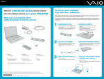
Unit start/stop
Power the unit.
The controller starts up and the main mask appears.
Check the status of the unit and presence of shut-down alarms.
for 2" The pump (if installed) starts immediately.
After a delay set on the electronic board the refrigerant compressor starts up.
Hold down button
.
%
%
+0
176
10
7PKVCEVKXG
To switch the unit off hold down button
1.2
Buttons
again for 2". The controller remains active.
The meaning of the controller buttons depends on the active mask and function. A table summarising all the
types of buttons present on the controller is given below.
Icons
!
ER 0702÷1402
Function
Buttons to scroll through stages and masks
Buttons to scroll through, select, increase or decrease the parameter values
Buttons to scroll through all alarm messages in stage Alarm
Button to quit the field displayed and return to the higher level stage
Enter a stage, activate and confirm the value
Access the stage relative to the set-point values
Access the stage in which the values detected by the controller are displayed
Access the free menu
Access the menu with password
Enter the stage relative to the alarms
Switch the unit on
Display values relative to circuit 1
Display values relative to circuit 2
Reset all alarms
Reset one alarm at a time
The data in this manual are not binding and may be changed by the manufacturer without notice. Reproduction of this manual is strictly prohibited.
ENGLISH
EN
CHAPTER 1
1.1
1
2
EN
OPERATING AND MAINTENANCE MANUAL
User's Quick Guide
1.3
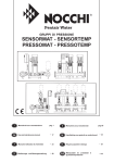
Changing the set-point
ENGLISH
The unit can be either on or off without affecting the procedure.
From the main mask press
.
+0
176
%
%
1((
7PKVQHH
Once you have entered the Set stage, scroll through masks
using
until reaching mask St002.
Press
to display the Summer Set-point.
Press
.
The parameter starts flashing.
Use
to scroll through the values.
Press
to confirm.
Press
to quit the stage.
1.4
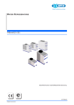
Alarms
The presence of active alarms is signalled by the icon
To access the Alarm stage from the main mask press
.
.
+0
176
%
%
1((
7PKVQHH
A list of active alarms is displayed in this stage. Use
scroll through the alarms.
Use
to reset the alarms.
indicates that the alarm can be reset.
Press
the alarm.
toto reset
Press
quit the stage.
to
Icon
The data in this manual are not binding and may be changed by the manufacturer without notice. Reproduction of this manual is strictly prohibited.
ER 0702÷1402
Contents
CONTENTS
USER'S QUICK GUIDE ........................................................................................................................ 1
1.1
1.2
1.3
1.4
Unit start/stop................................................................................................... 1
Buttons ............................................................................................................. 1
Changing the set-point ..................................................................................... 2
Alarms.............................................................................................................. 2
CONTENTS ........................................................................................................................................... 3
INSTALLATION .................................................................................................................................... 5
2.1
2.2
2.3
Foreword.......................................................................................................... 5
Symbols ........................................................................................................... 5
Installation ....................................................................................................... 6
2.3.1 Inspection ......................................................................................................... 6
2.3.2 Location ............................................................................................................ 6
2.3.3 Hydraulic Connections ..................................................................................... 7
2.3.4 Freeze protection .............................................................................................. 9
2.3.5 Electrical connections .................................................................................... 10
SAFETY .............................................................................................................................................. 11
3.1
3.2
General........................................................................................................... 11
General precautions ....................................................................................... 12
3.2.1
3.2.2
3.2.3
3.3
Precautions during lifting and transport ........................................................ 12
Precautions to be adopted during operation .................................................. 12
Precautions for maintenance and repair ........................................................ 12
Refrigerants.................................................................................................... 14
GENERAL INFORMATION ................................................................................................................. 15
4.1
4.2
4.3
4.4
4.5
How to interpret the model ............................................................................ 15
How to interpret the codes ............................................................................ 15
Data plate ....................................................................................................... 15
Performance data ........................................................................................... 16
How to interpret the alphanumeric string ...................................................... 16
DESCRIPTION .................................................................................................................................... 17
5.1
5.2
Operating principle ........................................................................................ 17
Components ................................................................................................... 17
5.2.1
5.2.2
5.2.3
5.2.4
5.3
Hydraulic system (optional)........................................................................... 18
5.3.1
5.3.2
5.4
5.5
Compressors ................................................................................................... 17
Condensers ..................................................................................................... 17
Fans ................................................................................................................ 17
Evaporator ...................................................................................................... 18
Cabinet ........................................................................................................... 18
Protection rating ............................................................................................ 18
Electrical circuit ............................................................................................. 18
Overall dimensions ........................................................................................ 18
FUNCTIONS AND COMPONENTS OF THE UNIT ................................................................................. 19
6.1
6.2
Automatic restart............................................................................................ 19
Set-point management ................................................................................... 19
6.2.1
6.2.2
6.2.3
6.2.4
6.2.5
6.3
6.4
Temperature control....................................................................................... 20
Compressors management ............................................................................. 21
6.4.1
6.4.2
6.5
Step Control .................................................................................................... 22
Variable speed control ................................................................................... 22
Water pump management .............................................................................. 23
6.6.1
6.7
6.8
Unloading procedure ..................................................................................... 21
Compressor protection ................................................................................... 21
Fans management .......................................................................................... 22
6.5.1
6.5.2
6.6
Fixed set-point ................................................................................................ 19
Compensated set-point ................................................................................... 19
Dual set-point ................................................................................................. 20
Time band variable set-point .......................................................................... 20
Variable set-point from digital input (Multifunction) .................................... 20
Automatic/Manual rotation ............................................................................ 23
Supervision System........................................................................................ 24
High pressure switches (HP).......................................................................... 24
ER 0702÷1402
The data in this manual are not binding and may be changed by the manufacturer without notice. Reproduction of this manual is strictly prohibited.
3
EN
ENGLISH
OPERATING AND MAINTENANCE MANUAL
4
OPERATING AND MAINTENANCE MANUAL
Contents
EN
6.9
Temperature and pressure transducers ........................................................... 25
ENGLISH
6.10
6.11
6.12
6.13
6.14
6.15
Water differential pressure switch.................................................................. 25
Forced ventilation of the electrical board....................................................... 25
-20 function (optional) ................................................................................... 26
Antifreeze control........................................................................................... 26
Electric panel heater (optional) ...................................................................... 26
Antifreeze heater and tank heater (optional) .................................................. 27
6.9.1
Pressure transducers ......................................................................................25
START-UP ..........................................................................................................................................29
ELECTRONIC CONTROLLER .............................................................................................................31
8.1
Interface.......................................................................................................... 31
8.2
8.3
Navigation ...................................................................................................... 33
Main mask ...................................................................................................... 34
8.4
Icons ............................................................................................................... 35
8.1.1
8.3.1
8.4.1
8.4.2
8.5
Graphic conventions .......................................................................................32
Other masks ....................................................................................................35
Main icons .......................................................................................................35
Menu stage icons ............................................................................................36
Using stages and masks.................................................................................. 36
8.5.1 Switching on and off the unit ..........................................................................37
8.5.2 Setting the language ........................................................................................38
8.5.3 Setting date and time .......................................................................................38
8.5.4 Changing the set-point ....................................................................................39
8.5.5 Changing the differential ................................................................................39
MASKS ...............................................................................................................................................40
8.6
8.7
8.8
8.9
Set-point stage ................................................................................................ 40
User stage ....................................................................................................... 41
Menu Stage..................................................................................................... 42
Alarm stage .................................................................................................... 44
OPERATION AND MAINTENANCE .....................................................................................................45
9.1
9.2
Operation........................................................................................................ 45
Maintenance ................................................................................................... 45
9.2.1 Access to the unit's internal compartments .....................................................45
9.2.2 Planning of checks and maintenance operations ...........................................46
TROUBLESHOOTING..........................................................................................................................47
10.1
Alarm signals ................................................................................................. 48
APPENDIX.......................................................................................................................................51
The data in this manual are not binding and may be changed by the manufacturer without notice. Reproduction of this manual is strictly prohibited.
ER 0702÷1402
OPERATING AND MAINTENANCE MANUAL
Installation
EN
ENGLISH
CHAPTER 2
INSTALLATION
2.1
Foreword
This manual is addressed to personnel responsible for installing, using and servicing the unit. The unit described
is designated WATER CHILLER or simply CHILLER. The expression “pressure” is used to indicate relative
pressure.
2.2
Symbols
Symbols present on the unit and also in the dimensional drawings and refrigerant circuit diagrams.
Unit water inlet
Unit water outlet
Heat recovery exchanger or
desuperheater water inlet (models
with heat recovery exchanger or
desuperheater only)
Heat recovery exchanger or
desuperheater water outlet
(models with heat recovery
exchanger or desuperheater only)
Indication of the axis of reference
for lifting operations
Unit drain point
Electric shock hazard
Flow of cooling air
Direction of flow of refrigerant
fluid
Rotation direction of pump
(if present) and fans
Risk of injury due to sharp edges
Risk of burns from contact with
high-temperature surfaces
Opening to use to insert bars for
unit lifting purposes
ER 0702÷1402
5
The data in this manual are not binding and may be changed by the manufacturer without notice. Reproduction of this manual is strictly prohibited.
6
EN
OPERATING AND MAINTENANCE MANUAL
Installation
Installation
2.3
ENGLISH
ATTENTION
Before installing or operating these units, read the chapter concerning “ Safety”.
2.3.1
I nspection
As soon as the unit has been unpacked check it carefully for damage.
2.3.2
Lo cation
1. The unit can be installed outdoors or indoors.
2. If the unit is installed indoors the place of installation must be well ventilated. In certain cases it may
be necessary to install ventilation fans or extractor fans in order to reduce room temperature.
3. The interior air must be clean and free from inflammable gases or solvent vapours.
4. The minimum and maximum ambient temperatures are specified on the unit's nameplate. In extreme
temperature conditions the protection devices may trip.
5. The unit can be positioned on any flat surface that is adequately sized to support its weight.
6. Leave free clearance of approximately 1 metre around the unit for access during service interventions
(see Attachments).
7. Never obstruct or disturb the thermal exchange air flow over the condenser. The air flow enters the
unit through the condenser finned coils and is expelled to the exterior by the fans. Position the unit in
such a way that the thermal exchange air cannot recirculate to the intake grilles. Make sure no warm
air flows from other cooling systems is aspirated.
8. Do not install the plant in sites exposed to strong winds; if unavoidable, install suitable windscreens.
The data in this manual are not binding and may be changed by the manufacturer without notice. Reproduction of this manual is strictly prohibited.
ER 0702÷1402
OPERATING AND MAINTENANCE MANUAL
Installation
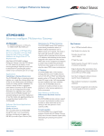
2.3.3
7
EN
Hydraulic Connections
1. Connect the unit to the water pipes as shown in the diagram below.
2. Provide two valves (one at the inlet, one at the outlet) to isolate the unit in the case of maintenance
work without having to empty the user water circuit.
3. If the unit is not equipped with a hydraulic unit as standard, ensure that the suction line of the pump
installed subsequently by the user is connected directly to the unit in order to avoid excessively high
pressure on the condenser side.
A clamping half collars
B seal
C weld-on stub pipe
D evaporator stub pipe
“VICTAULIC” CONNECTION
NOTE
For correct operation of the unit install a filter to intercept debris in the water inlet pipe. Failure to observe this
prescription can result in irreparable damage to the evaporator.
ER 0702÷1402
The data in this manual are not binding and may be changed by the manufacturer without notice. Reproduction of this manual is strictly prohibited.
ENGLISH
The unit is equipped with threaded or “Victaulic” connections (see diagram below).
EN
OPERATING AND MAINTENANCE MANUAL
Installation
The hydraulic circuit must be sized in such a way as to comply with the pressure limit value specified on the data
ENGLISH
plate and ensure the flow rate shown in the following table is not exceeded:
SHELL AND TUBE EVAPORATOR
Maximum flow rate [m3/h]
SHELL AND TUBE EVAPORATOR
Minimum flow rate [m3/h]
ER 0702
30.0
13.9
ER 0802
41.0
9.3
ER 0902
43.0
17.9
ER 1002
43.0
18.8
ER 1102
65.0
21.2
ER 1202
65.0
22.9
ER 1302
68.0
25.5
ER 1402
68.0
27.3
Evaporator pressure drops
ER1102÷1202
ER0702
ER0802
Evaporator DeltaP (Kpa)
8
ER1302÷1402
ER0902÷1002
Water flow rate (m3/h)
The data in this manual are not binding and may be changed by the manufacturer without notice. Reproduction of this manual is strictly prohibited.
ER 0702÷1402
OPERATING AND MAINTENANCE MANUAL
Installation
2.3.4
9
EN
Freeze protection
season the unit may be subject to temperatures that are lower than 0 °C. In such cases if the water circuit is not
drained, to avoid ice formation ethylene glycol antifreeze should be added to the water in the following
percentages:
Ambient temperature
up to [°C]
Ethylene Glycol
[% in weight]
0
0
-5
15
-10
25
-15
30
-20
40
Depending on the cooled water outlet temperature, antifreeze (ethylene glycol) must be added in the following
percentages to prevent the formation of ice:
Water outlet temperature
up to [°C]
ER 0702÷1402
Ethylene Glycol
[% in weight]
4
0
0
19
-5
27
-10
34
-15
39
-20
44
-15
35
-19.9
40
The data in this manual are not binding and may be changed by the manufacturer without notice. Reproduction of this manual is strictly prohibited.
ENGLISH
Even if the minimum working ambient temperature is higher than 0 °C, during shutdown periods in the winter
10
EN
OPERATING AND MAINTENANCE MANUAL
Installation
2.3.5
E lectrical connections
ENGLISH
The unit's connection to the power supply must be made in compliance with laws and prescriptions in force in
the place of installation.
The voltage, frequency and number of phases must comply with the data on the unit's nameplate. The power
supply voltage must not be outside the tolerances shown on the electrical diagram, even in terms of transients.
Unless otherwise specified, the frequency tolerance is +/-1% of the nominal value (+/-2% for short periods).
With a three-phase power supply the voltage must be symmetrical (the effective values of phase to phase
voltages and consecutive phase angles must be identical). In particular, unless otherwise indicated, the maximum
permissible phase imbalance is 2%, calculated according to the formula
Max.differenceof phasevoltagewith respect toVavg
u100
Vavg
Vavg = average phase voltage
The line conductor and neutral conductor are not interchangeable and their positions cannot be switched.
For the electrical power supply:
1.
E
Connect the unit (PE terminal in the electrical cabinet) to the electrical earthing system of the
building.
2.
E ensure automatic interruption of the power supply in the event of an insulation fault (protection
against indirect contact in compliance with the prescriptions of IEC 60364) by means of a residual
current device (the nominal trip current of which should normally be set to 0.03 A).
3. make sure the level of protection against indirect contact at the source of the power feeding cable is
equivalent at least to IP2X or IPXXB (refer to CEI EN 60529).
4. at the start of the power cable install a device that protects it from current surges (short-circuits)
(refer to the indications given in the electrical diagram).
5. use conductors rated to carry the maximum current required at the maximum operating ambient
temperature, according to the chosen installation type (IEC 5-60364-523) (see the indications on the
electrical diagram).
Indications on the electrical diagram:
•
•
maximum permissible size of the fuse type gG.
In general, fuses can be replaced by an automatic circuit breaker set in relation to the unit's
maximum current input (consult the manufacturer if necessary)
section and type of power cable (if not already supplied):
Installation: insulated conductors or multicore cable in an overhead or wall-mounted cable duct
(type C in compliance with IEC 5-523-60364 1983) without any other cables in contact
operating temperature: maximum working ambient temperature for the unit
cable type: copper conductors, 70 °C PVC insulation (unless otherwise specified) or 90 °C EPR
insulation
The data in this manual are not binding and may be changed by the manufacturer without notice. Reproduction of this manual is strictly prohibited.
ER 0702÷1402
OPERATING AND MAINTENANCE MANUAL
CHAPTER 3
EN
SAFETY
This plant is designed for safety in its intended use, provided it is installed, commissioned, and serviced in
compliance with the instructions given in the present manual.
ATTENTION
All persons who interact with the plant must be informed of the indications, regulations and prescriptions given
in this manual.
Pay special attention when working on the unit: the unit contains electrical components that operate at mains
voltage and also moving parts such as fan units.
To avoid the risk of accidents, disconnect the unit from the power supply before working inside it.
Any maintenance operations other than normal tasks must be executed by skilled and suitably qualified personnel.
Keep unauthorized persons (e.g. children) away from the place of installation of the unit.
3.1
General
When handling or servicing the unit, personnel must work safely and comply with the prescriptions concerning
health and safety in the installation site.
ATTENTION
Numerous accidents that occur during operation and maintenance of the units are caused by failure to comply
with basic safety rules or precautions.
Frequently accidents can be avoided by early identification of potentially hazardous situations.
The user must ensure that all personnel involved in operating and servicing the unit have read and understood
all the warnings, precautions, prohibitions and notes given in this manual and affixed to the unit.
Improper operation or maintenance of the unit and auxiliary equipment can be dangerous and can cause serious
or fatal accidents.
It is not possible to cover all possible circumstances that could feasibly give rise to potential hazards for persons.
Therefore the notes concerning safety in this manual cannot be considered to be exhaustive.
If the user adopts operational procedures or uses tools or working procedures that are not specifically
recommended, care must be taken to ensure that the unit and the auxiliary equipment are not damaged or made
unsafe and that no risks emerge in relation to persons or property.
ATTENTION
Use exclusively suitable methods that offer the maximum environmental respect in daily operation, routine or
supplementary maintenance, and at the time of decommissioning of the plant.
Any improper conduct or incorrect use of the unit by the user automatically releases the manufacturer from all
liability for possible damage, injury and/or accidents affecting persons or property.
Arbitrary modifications made to the unit will automatically invalidate all forms of guarantee provided by the
manufacturer.
ER 0702÷1402
11
ENGLISH
Safety
The data in this manual are not binding and may be changed by the manufacturer without notice. Reproduction of this manual is strictly prohibited.
12
EN
OPERATING AND MAINTENANCE MANUAL
Safety
3.2
ENGLISH
3.2.1
General precautions
Precautions during lifting and transport
Check that all chains, hooks, shackles and slings are in good condition and of suitable capacity.
Lifting accessories must be tested and approved in compliance with statutory safety regulations in force in the
place of installation.
Cables, chains or ropes must never be attached directly to lifting eyebolts.
Always use a correctly positioned intermediate shackle or hook.
Ensure that lifting cables do not describe excessively tight bends.
Use a spreader bar to avoid lateral loading of hooks and eyebolts.
ATTENTION
When a load is lifted from the ground keep well clear of the area beneath the load and the immediately
surrounding area.
Keep lifting acceleration and speed well within safety limits and never leave a suspended load attached to a hoist
any longer than strictly necessary
3.2.2
P recautions to be adopted during operation
The unit must be operated by competent personnel under the guidance of a qualified supervisor.
All connections of the refrigerant circuit, electrical system and control unit wiring must be easily identifiable,
painted or marked clearly in compliance with local safety prescriptions in force in the place of installation.
ATTENTION
Do not remove or tamper with safety devices, protections, or the insulating materials installed in the unit or in
the auxiliary equipment.
All electrical connections must comply with local prescriptions in force in the installation site.
The unit and its auxiliary equipment must be connected to earth and protected against short circuits and
overloads.
When the main power switch is closed the voltage in the electrical circuit assumes potentially lethal values.
The maximum precautions must be adopted if work is to be carried out on the electrical circuit.
3.2.3
P recautions for maintenance and repair
ATTENTION
When it is necessary to discharge waste material do not pollute water pipelines, groundwater or watercourses.
Avoid the combustion of materials that could cause atmospheric pollution. Use exclusively suitable storage
methods that offer the maximum environmental respect.
Keep a written record of all work carried out on the unit and the auxiliary equipment. The frequency and nature
of the work required of the unit must not cause abnormal operating conditions.
ATTENTION
Use exclusively the refrigerant specified on the unit’s data plate.
Make sure that all the instructions concerning operation and maintenance are followed scrupulously and that the
entire unit and all the accessories and safety devices are maintained in proper working order. The accuracy of
temperature and pressure measuring devices must be checked regularly. Such devices must be replaced when the
permitted tolerance values are exceeded.
The data in this manual are not binding and may be changed by the manufacturer without notice. Reproduction of this manual is strictly prohibited.
ER 0702÷1402
Safety
ATTENTION
Do not weld or perform work that generates heat close to a system that contains oil or inflammable liquids.
Systems that may contain oil or inflammable liquids must be completely drained and cleaned, for example with
steam, before performing any such operations.
To prevent an increase in working temperature and pressure values clean the heat exchange surfaces (e.g. the fins
of condensers) regularly. For all units establish a suitable time interval for cleaning procedures.
ATTENTION
DO NOT damage the pressure relief valves and other pressure limiting devices.
Do not clog these devices with paint, oil, or accumulated dirt.
Use exclusively original spare parts.
Never use an open flame as a light source to inspect parts of the unit.
When a repair has been completed make sure that no tools or detached parts are left in the unit.
ATTENTION
Check the direction of rotation of the motors when starting the unit for the first time and after work has been
performed on the electrical connections or on the power supply sectioning device.
All the protections must be refitted following maintenance or repair work.
Do not use inflammable liquids to clean components while the unit is running.
If non-inflammable hydrocarbons containing chloride are used all the relevant safety precautions must be
adopted to protect against the toxic fumes that may be given off.
ATTENTION
Before removing any panels or dismantling any parts of the unit perform the following steps:
- Isolate the unit from the electrical power supply by disconnecting the supply upstream of the power feeding
line.
- Lock out the disconnect switch on the “OFF” position by fitting a padlock.
- Place a sign on the disconnect switch handle stating “WORK IN PROGRESS - DO NOT CONNECT POWER”.
- Do not set the electrical power switch to ON or attempt to start the unit if the warning sign is displayed.
ER 0702÷1402
The data in this manual are not binding and may be changed by the manufacturer without notice. Reproduction of this manual is strictly prohibited.
13
EN
ENGLISH
OPERATING AND MAINTENANCE MANUAL
14
EN
OPERATING AND MAINTENANCE MANUAL
Safety
3.3
Refrigerants
ENGLISH
ATTENTION
See the refrigerants safety datasheet in the manual appendix.
These units may be charged exclusively with R407C.
Do not replace the refrigerant with a different type or mix two different types of refrigerant.
To clean a refrigerant circuit that has been seriously contaminated, e.g. following a compressor burn-out, the
relative work must be carried out by an expert refrigeration engineer.
The use and storage of cylinders containing refrigerants must be in compliance with the prescriptions of the
manufacturers of the cylinders and in compliance with the applicable safety laws and prescriptions in force in
the place of installation.
The data in this manual are not binding and may be changed by the manufacturer without notice. Reproduction of this manual is strictly prohibited.
ER 0702÷1402
OPERATING AND MAINTENANCE MANUAL
General Information
GENERAL INFORMATION
These units are designed to cool a liquid (WATER in the majority of applications).
The term “WATER” is used for the sake of simplicity to identify the liquid to be cooled, even if the liquid
involved is not water (e.g. a water and ethylene glycol solution).
The liquid to be cooled must be compatible with the materials used.
This analysis must be carried out when installing the unit.
ATTENTION
Requests for spare parts and any information must be addressed to the local dealer or service centre, specifying
the MODEL and SERIAL NUMBER shown on the unit's nameplate and on the first page of this manual.
How to interpret the model
MODEL
DESCRIPTION
ER ¡¡¡¡¡¡¡
Unit version (N, SN, H or SSN)
Nominal power of compressor expressed in HP
Hercules
How to interpret the codes
4.2
/N
/SN
/SSN
/H
Low noise operation value: standard. Compressors compartment only partially acoustically
insulated.
Low noise operation value: medium. Acoustically insulated compressors compartment. Low speed
fans.
Low noise operation value: high. Compressors compartment with high efficiency acoustic
insulation.
High ambient air temperature units.
4.3
Data plate
The data plate affixed to the unit shows the main technical data.
MODEL and CODE
Identify the size of the unit (see chap. “ General Information”) and the type
of construction.
MANUAL
Code number of this manual.
SERIAL NUMBER
Unit serial number or manufacturing number.
YEAR OF CONSTRUCTION
Year of unit's final testing.
VOLTAGE/PHASES/
FREQUENCY
Power supply specifications.
MAX CURRENT INPUT
IMAX
Unit current input in limit working conditions
ER 0702÷1402
The data in this manual are not binding and may be changed by the manufacturer without notice. Reproduction of this manual is strictly prohibited.
ENGLISH
EN
CHAPTER 4
4.1
15
16
EN
OPERATING AND MAINTENANCE MANUAL
General Information
ENGLISH
INSTALLED POWER
P MAX
Unit power input in limit working conditions
PROTECTION RATING
Protection rating of the entire unit, according to European standard EN
60529.
REFRIGERANT
Type of refrigerant charge with which the unit is filled.
REFRIGERANT CHARGE
Quantity of refrigerant supplied to the circuit.
MAX. REFRIGERANT PRESS.
HP SIDE
Refrigerant circuit design pressure (high pressure side).
MAX. REFRIGERANT PRESS.
LP SIDE
Refrigerant circuit design pressure (low pressure side).
USER CIRC. FLUID
Fluid cooled or heated by the unit (usually: water).
MAX. WORKING PRESSURE
User circuit maximum design pressure.
MAX TEMPERATURE
User circuit maximum design temperature - not to be confused with the
maximum working temperature, which is specified at the time of the offer.
SOUND PRESSURE LEVEL
Free field sound pressure level in hemispherical radiation conditions
(open field) at a distance of 1 m from the condenser side of the unit and a
height of 1.2 m from the ground.
AMBIENT TEMPERATURE
Thermal exchange air minimum and maximum temperature values.
WEIGHT
Approximate weight of the unit without packaging.
4.4
Performance data
The performance of the chiller depends mainly on the flow rate and temperature of chilled water and ambient
temperature.
Performance values are defined at the time of the contract, refer to the offer data if necessary.
4.5
How to interpret the alphanumeric
string
ATTENTION
See the table concerning the alphanumeric string in the appendix.
The alphanumeric string is shown on the metal data plate on the cover page of this manual.
This symbol shown alongside appears in some refrigerant circuit diagrams and
electrical diagrams. This symbol refers to the alphanumeric string reported in the
manual. The upper box (X) identifies the position of the string, the lower box (Y)
identifies the assigned value.
The empty alphanumerical string is circled in the adjacent figure;
each position in the upper row is associated with an alphanumeric
value in the lower row (0, 1, 2, A, B, etc.) and each character is
associated with a specific feature of the unit.
The data in this manual are not binding and may be changed by the manufacturer without notice. Reproduction of this manual is strictly prohibited.
ER 0702÷1402
OPERATING AND MAINTENANCE MANUAL
CHAPTER 5
EN
DESCRIPTION
Operating principle
5.1
The unit is equipped with two separate and independent refrigerant circuits. A shell and tube evaporator allows
heat exchange between the refrigerant and the process fluid.
Suitable compressors are utilised to compress freon in order to achieve a change from the gaseous to the liquid
phase. In this stage the refrigerant gas releases energy in the form of heat.
The liquid refrigerant enters the evaporator where it expands and returns to its initial gaseous state. As it returns
to the gaseous state the refrigerant absorbs energy in the form of heat. In compliance with the first principle of
thermodynamics, the heat is released by the process fluid that flows over the surfaces of the evaporator at a
temperature that is higher than that of the refrigerant fluid.
The following parameters are managed by an electronic control unit:
•
•
5.2
5.2.1
evaporator water inlet temperature to keep it within the preset limits;
the evaporator water outlet temperature and the pressure difference between evaporator inlet and
outlet water to avoid the risk of freezing in low or zero flow conditions.
Components
Compressors
The compressors are of the SCROLL type and are quipped with built-in overtemperature
protection in the motor windings, check valve on the discharge line and by-pass between
suction and discharge lines.
Shut-off valves on the suction and discharge lines can be supplied on request.
Each circuit of the units is equipped with an oil equalisation line between the compressors.
The compressors are installed on rubber antivibration mounts and housed in a compartment
that is acoustically insulated by means of sound-absorbing matting in low noise versions
(SN and SSN).
5.2.2
Co n d e n s e r s
The condensers are heat exchangers of the finned core type, cooled by a flow of air
supplied by the fans, and equipped with copper tubes, aluminium fins, and galvanized
carbon steel shoulders. Each refrigerant circuit includes a condensing coil and an
associated row of fans.
5.2.3
Fans
The fans are of the axial type, comprising a diecast aluminium fan wheel
with sickle shaped blades.
The fan protection rating is IP54. All fans feature insulation class F to
ensure they are compatible with outdoor operation in all climates.
Fan assembly is completed by an aerodynamically profiled port made of
galvanized sheet steel and safety grilles downstream and upstream of the air
flow.
ER 0702÷1402
17
ENGLISH
Description
The data in this manual are not binding and may be changed by the manufacturer without notice. Reproduction of this manual is strictly prohibited.
18
EN
OPERATING AND MAINTENANCE MANUAL
Description
5.2.4
E vaporator
ENGLISH
Shell and tube type:
The evaporator is composed of an “U”-type shell and tube exchanger in which the refrigerant from the
refrigerant circuit evaporates, simultaneously absorbing heat from the water to be chilled that is flowing through
the shellside.
The evaporator shell, tube and headers are made of carbon steel, the tubes are copper and the diaphragms are
brass.
The connections are threaded or of the Victaulic type.
The evaporator is equipped with a drain cock for easy emptying of the water contents when the plant is to be
drained (see chapter “ Operation and Maintenance”).
Hydraulic system (optional)
5.3
The units can be equipped with a hydraulic system on request. The system,
which is installed on board the unit, is composed of centrifugal pump and
storage tank and supplied with the following accessories:
•
•
•
•
•
•
Units can be
expansion vessel
water pressure relief valve
automatic air bleed valve
discharge valve
water pressure gauge at pump outlet
electric heaters (optional).
equipped with a medium pressure head pump on request.
Pump installation is envisaged in the following configurations:
•
•
•
•
5.3.1
single pump
double pump (one in stand-by)
pump and tank assembly
double pump (one in stand-by) and tank unit.
C abinet
The cabinet is made of galvanized panels with polyester powder coating.
5.3.2
P ro tection ratin g
The protection rating of the entire unit is IP54 with insulation class F to ensure it is compatible with outdoor
operation in all climates.
5.4
Electrical circuit
The electrical circuit schematic is given in the annexed diagrams.
5.5
Overall dimensions
See attachments
The data in this manual are not binding and may be changed by the manufacturer without notice. Reproduction of this manual is strictly prohibited.
ER 0702÷1402
OPERATING AND MAINTENANCE MANUAL
Functions and components of the unit
AND COMPONENTS OF THE UNIT
This chapter provides an overview of the unit main functions. Some functions may be inactive or not present in
the unit for specific requirements. Refer to the definitive offer data.
Automatic restart
6.1
This function serves to restore unit status in the event of sudden power loss. The unit will restart in ON mode if
it was active ON at the time of power loss, and remain OFF if it was OFF at the time of power loss.
Set-point management
6.2
The set-point is the temperature value of the user water in relation to the control probe setting. The controller
can manage different set-point modes:
•
•
•
•
•
6.2.1
fixed set-point;
compensated set-point;
dual set-point;
time band variable set-point;
set-point from analog input (inactive).
Fixed set-point
Set-point and differential values relative to water temperature control do not change in relation to external
actions or conditions. To change the set-point edit the parameter value manually, entering a new value.
6.2.2
Compensated set-point
The compensated set-point serves to adapt the set-point to a value measured on the basis of the ambient
temperature reading.
The following diagram shows the set-point curve on the basis of the various parameter settings:
Calculated
set-point
Maximum
Compensation
CHILLER
Set-point
Compensation
Start
ER 0702÷1402
Compensation
Differential
Ambient
Temperature
The data in this manual are not binding and may be changed by the manufacturer without notice. Reproduction of this manual is strictly prohibited.
ENGLISH
EN
CHAPTER 6
FUNCTIONS
19
20
EN
OPERATING AND MAINTENANCE MANUAL
Functions and components of the unit
Diagram with negative “Compensation Differential”;
ENGLISH
Calculated
Set-point
Maximum
Compensation
CHILLER
Set-point
Compensation
Start
6.2.3
Compensation
Differential
Ambient
Temperature
Dual set-point
A second working set-point can be programmed. The set-point to be utilised is discriminated by means of a
control unit digital input.
6.2.4
Time band variable set-point
With time-band variable set-point operation four time-bands can be programmed with different set-points.
Once the programmed time has been reached, the controller changes the unit set-point according to the value
programmed for the time-band in question.
6.2.5
Variable set-point from digital input (Multifunction)
The set-point is variable in accordance with the temperature value constantly detected by the specified probe.
The following diagram shows the operating logic:
Variable
set-point
Maximum
set-point
Minimum
set-point
4mA
20mA
Analog input
4 ÷ 20mA
Temperature control
6.3
The temperature control strategy adjusts the unit in relation to the user water temperature value. There are two
main factors involved: temperature and time. There are two types of control system: P.I.D. and Neutral Zone.
PID mode
P+I+D temperature control takes account of:
•
•
•
the instantaneous deviation value with respect to the SET to which a Proportional Value P is
assigned;
the time during which the temperature value remains stable by means of the Integral Error I ;
the rate of change of the user water temperature by means of the Derivative value D.
The data in this manual are not binding and may be changed by the manufacturer without notice. Reproduction of this manual is strictly prohibited.
ER 0702÷1402
OPERATING AND MAINTENANCE MANUAL
Functions and components of the unit
21
EN
Neutral Zone
compressors will be stopped (consecutive compressor stops will occur with a preset delay interval) until the
measured temperature value returns to within the Neutral Zone. When the temperature value measured by the
probe is higher than the set-point + differential value (hence above the Neutral Zone), one or more compressors
will be started (consecutive compressor starts occur in accordance with a preset time lag) until the measured
temperature value returns to within the Neutral Zone. The Neutral Zone Logic diagram illustrates explains how
an increase or reduction in cooling demand causes, respectively, compressor starts or stops, with variable start
and stop times on the basis of the zone in which the system is operating.
WATER
TEMPERATURE
SET+DIFF.
Neutral Zone
SET
TIME
COMPRESSORS
CIRC.1
CIRC.2
STATUS
Compr. 4 ON
{
{
Compr. 3 ON
Compr. 2 ON
Compr. 1 ON
Compr. OFF
starts time lag
stops time lag
TIME
Compressors management
6.4
“Rotation” refers to the function that serves to optimise starts, stops and number of working hours of all the
unit's compressors. With the aim of improving distribution of work loads it is also possible to implement rotation
of circuits. The controller stores the operating hours and number of starts of each compressor and the unit.
Setting an operating hours threshold value results in the generation of an alarm when the preset threshold is
reached. The alarm signals the need to carry out routine maintenance.
The alarm message does not shut down the unit.
The functions involved in compressors management are:
•
•
•
•
6.4.1
Proportional Integral Derivative control (PID) and Neutral Zone control
The Pump-down function controls stops and starts to prevent them drawing in liquid refrigerant.
Compressors rotation
Circuits rotation
Un l o a d i n g p r o c e d u r e
The unloading procedure serves to halve the capacity of the circuit by switching off a compressor. This function
is activated when the heating demand is higher than the unit capacity. The unloading procedure serves to protect
the system from pointless and potentially harmful stress.
6.4.2
Compressor protection
The compressor protection prevents incorrect rotation of the compressor scrolls and the emergence of motor
windings overheating phenomena.
ER 0702÷1402
The data in this manual are not binding and may be changed by the manufacturer without notice. Reproduction of this manual is strictly prohibited.
ENGLISH
When the water temperature value is lower than the set-point value (hence below the Neutral Zone), one or more
Functions and components of the unit
Fans management
6.5
ways:
•
•
by Step Control
by stepless Speed Control
6.5.1
S tep Co ntr ol
The controller activates step control of the fans on the basis of the pressure values measured by the high pressure
transducers on the refrigerant circuit pipes. The activation of one fans step corresponds to starting of one
subgroup composed of several fans. Fig.1 describes the operating logic of 2-step control.
FAN STATUS
OFF
STEP 2
ON
OFF
STEP 1
ON
OFF
}
VALUE DETECTED
Set 2
ENGLISH
High pressure transducers are connected to the controller and provide the facility to manage the fans in two
Set 1
EN
OPERATING AND MAINTENANCE MANUAL
Diff.
22
BY HIGH PRESSURE
TRANSDUCERS
BHP
Fig. 1 FANS STEP ACTIVATION LOGIC
circuit 1
1
2
Elec. Panel
1
2
circuit 2
6.5.2
circuit 1
1
1
1
Elec. Panel
1
The fans are combined in groups.
No.1 fans start.
Next step: no. 2 fans start.
2
2
circuit 2
V ariable speed control
The electronic fan speed control system is of the phase cut-off type. The system features one speed controller for
each refrigerant circuit.
On the units each group of fans can run at a different speed depending on the pressure value detected by the
corresponding pressure transducer (-BHP transducers).
In normal operation the fans are stopped when pressure read by the high pressure transducers (-BHP) is lower
than the set-point value, or when the last compressor is stopped.
The data in this manual are not binding and may be changed by the manufacturer without notice. Reproduction of this manual is strictly prohibited.
ER 0702÷1402
OPERATING AND MAINTENANCE MANUAL
Functions and components of the unit
23
EN
Fig.2 describes the operating logic of the fan speed control system.
ENGLISH
FAN SPEED
maximum speed
%
fans ON
minimum speed
%
fans OFF
}
Set
Diff
Set+Diff
VALUE DETECTED
BY THE HIGH PRESSURE
TRANSDUCERS
Fig. 2 FANS ACTIVATION LOGIC WITH SPEED CONTROL
Water pump management
6.6
Water pumps can be installed on all units on request only.
Installation of a pump is possible with different configurations as described in chapter 5.3 “Hydraulic system
(optional)” .
the pump (if installed) starts.
Once the unit has stopped by pressing
the pump continues to run for a programmed delay time. The pump
stops only in presence of shut-down alarms.
On starting the unit by pressing
Pump antifreeze function
The controller envisages the use of the pumps as a measure against icing up of the evaporator.
It is therefore possible to enable the pumps for start-up in accordance with the antifreeze strategy.
6.6.1
Au t o m a t i c / M a n u a l r o t a t i o n
With two pumps installed, one pump runs while the second is in stand-by. If the working pump breaks down,
the second pump automatically takes over. Other rotation modes of pumping units are:
•
•
•
•
Start
Manual
Hours
Start+hours
Start
Alternatively, the pump that was previously idle during the previous start session is utilised.
Manual
Start of one pump is forced by the controller.
Hours
The pumps change over after a programmed interval.
Hours+start
At each new start command the pump that was previously stopped is started, but if the maximum number of
consecutive running hours is reached the pumps are switched over.
ATTENTION
Note that in “hours” rotation mode the hour counter function is reset when the unit is stopped. Selection of the
rotation type therefore depends on the type of use of the machine.
ER 0702÷1402
The data in this manual are not binding and may be changed by the manufacturer without notice. Reproduction of this manual is strictly prohibited.
24
EN
OPERATING AND MAINTENANCE MANUAL
Functions and components of the unit
Supervision System
6.7
ENGLISH
The controller can manage the following supervision protocols:
•
•
•
MODBUS
GSM
LONWORKS
High pressure switches (HP)
6.8
High pressure switches provide an additional electromechanical protection with respect to the protection offered
by the high pressure transducers installed in the unit.
HP switches are installed on the refrigerant compressor discharge line to prevent the arrival at pressure levels
that are potentially hazardous for proper operation of the unit and for personal safety.
•
ER0802÷1402
All refrigerant circuits are equipped with an automatic reset pressure switch on the high pressure
side. Tripping of this pressure switch opens the compressor power supply circuit (see electrical
diagram). When pressure decreases and falls below the reset point, the pressure switch resets
automatically and the unit can be restarted by pressing the electronic controller ALARM button.
• ER0802÷1402
All refrigerant circuits are equipped also with a pressure switch with manual reset on the high
pressure side of each circuit. Tripping of this pressure switch opens the compressor power supply
circuit (see electrical diagram). When pressure decreases and falls below the reset point, the
pressure switch must be reset manually, after which the unit can be restarted by pressing the
ALARM button on the electronic controller.
The high pressure switches are connected to the refrigerant circuit pipes by means of SCHRAEDER valves (with
needle) so there is no risk of refrigerant escaping if the pressure switches are to be replaced.
For correct operation of the unit the pressure switch trip and reset values must not differ from those
shown in the following table:
COMPONENT
REFRIGERANT
High pressure switch with manual
reset
High pressure switch with automatic
reset (manual calibration type)
TRIP
RESET
bar
°C
°F
bar
°C
°F
R407C
26.7
62.6
144.7
22.7
55.7
132.3
R407C
26.3
61.9
143.4
20.3
51.1
123.9
The data in this manual are not binding and may be changed by the manufacturer without notice. Reproduction of this manual is strictly prohibited.
ER 0702÷1402
OPERATING AND MAINTENANCE MANUAL
Functions and components of the unit
Temperature and pressure transducers
6.9
•
•
6.9.1
pressure transducers, powered directly by the controller;
temperature transducers.
Pressure transducers
Each refrigerant circuit is equipped with a low pressure transducer and a high pressure transducer.
These sensors detect compressor suction and discharge pressure values and adjust operation of the unit on the
basis of the programmed set-points.
By reading the parameters the following functions can be controlled for each circuit:
• high pressure alarm;
• low pressure alarm;
• unloading for high pressure;
• low pressure pump-down (not enabled);
• fans control;
• measurement of high and low pressure values.
Therefore, if pressure in one circuit increases or decreases with respect to the preset limit values, an alarm signal
can be tripped to stop the unit, start or stop the fans, and stop one or more compressors after a programmable
time interval.
6.10
Water differential pressure switch
The unit is equipped with a differential pressure switch that detects the water pressure difference between the
evaporator inlet and outlet pipes. When the pressure switch detects a 'p lower than 50 mbar (500 mmWg),
an alarm signal shuts down the unit once the preset time lag has elapsed. When 'p returns to above 50 mbar,
the unit can be restarted by pressing the ALARM button. This type of event should occur rarely and be of short
duration.
6.11
Forced ventilation of the electrical
board
The circulation fan is controlled by a thermostat positioned inside the electrical panel. It starts when the
temperature inside the electrical panel exceeds the thermostat’s set point.
Electrical panel fan state
ON
OFF
SETPOINT
Temperature
Temperature inside
the electrical panel
DIFFERENTIAL (Fixed)
The setpoint value is 40°C.
The differential value, 4°C, is fixed.
ER 0702÷1402
EN
ENGLISH
The unit is equipped with two types of transducers:
25
The data in this manual are not binding and may be changed by the manufacturer without notice. Reproduction of this manual is strictly prohibited.
26
EN
OPERATING AND MAINTENANCE MANUAL
Functions and components of the unit
6.12
-20 function (optional)
ENGLISH
This option is present only if the fan electronic regulation, the compressor carter resistance and the electrical
panel resistances are present. Antifreeze resistance kits are option furnished, in alternative to the glycol. They
protect the water circuit from ice formation with ambient temperatures until -20°C.
6.13
Antifreeze control
Antifreeze control actions depend on the temperature measured at the evaporator outlet.
When the temperature falls below the previously set antifreeze threshold value the controller generates an alarm
that shuts down the unit.
This alarm will remain active until the temperature returns to a value above the set-point + differential.
6.14
Electric panel heater (optional)
The electric panel of the units designed to work until -20°C is fitted with a fan-assisted heater which heats the
electrical components in order to protect them from low temperatures.
This heater is controlled by a thermostat inside the electric panel which activates it when the temperature inside
the panel falls below the set point less the differential.
Electric panel heater status
ON
OFF
DIFFERENTIAL (fixed)
SETPOINT
Temperature
Temperature inside
the electrical panel
The setpoint value is 5°C.
The differential value, 4°C, is fixed.
The data in this manual are not binding and may be changed by the manufacturer without notice. Reproduction of this manual is strictly prohibited.
ER 0702÷1402
Functions and components of the unit
Antifreeze heater and tank heater
(optional)
6.15
For further information refer to the electrical diagrams.
The antifreeze heater is installed only on request (optional).
Make sure the evaporator, pump (if installed), and storage tank (if installed) are protected against the risk of
freezing in installations subject to particularly severe ambient temperatures.
Different configurations are available:
•
•
•
hot wire heating element wrapped around the evaporator;
hot wire heating element wrapped around the evaporator and pump (if installed);
hot wire heating element wrapped around the evaporator and pump (if installed) and immersion
heater in the storage tank (if installed).
Activation of the hot wire heating elements is managed by the controller by means of an ambient temperature
probe located in the fans compartment behind the electrical cabinet.
SET-POINT
DIFFERENTIAL
3 °C
3 °C
hot wire heating elements
Activation of the immersion heater (storage tank) is managed by the thermostat with bulb located inside the tank.
SET-POINT
DIFFERENTIAL
3 °C
3 °C
immersion heater
The activation logic of the heaters is described below.
Heater status
ON
OFF
Temperature
DIFFERENTIAL
ER 0702÷1402
Thermostat
Set-point
The data in this manual are not binding and may be changed by the manufacturer without notice. Reproduction of this manual is strictly prohibited.
27
EN
ENGLISH
OPERATING AND MAINTENANCE MANUAL
28
OPERATING AND MAINTENANCE MANUAL
Functions and components of the unit
EN
ENGLISH
The data in this manual are not binding and may be changed by the manufacturer without notice. Reproduction of this manual is strictly prohibited.
ER 0702÷1402
OPERATING AND MAINTENANCE MANUAL
Start-up
START-UP
ATTENTION
Before starting this type of unit, ensure that all personnel involved have read and understood the “ Safety”
chapter in this manual.
1. The unit shut-off valves must be open.
2. With a “closed” type hydraulic circuit ensure that a suitably sized expansion vessel has been installed.
3. Check that the ambient temperature is within the range indicated on the unit's data plate.
4. Check that the main switch is in the OFF position (“O”).
5. Check that the unit power supply voltage is correct.
6. Power the unit by means of the line protection device.
7.Turn the unit main switch to the ON position (“I”).
When the unit is powered the control unit display switches on. Check on the
display for:
unit alarm
Time bands Off
Supervision Off
“External On/Off” Off
8. Models without pump:
before switching the unit on make sure the water pump is running and water is flowing through the
evaporator.
9. Models with discharge valves on compressors:
Check that the compressor discharge valves are open.
for 2" to start the unit The pump (if installed) starts immediately.
After a delay set on the electronic board the refrigerant compressor starts.
10. Press button
.
+0
176
%
%
10
7PKVCEVKXG
again for 2" to stop the unit. The controller remains active.
11. Compressors, pump and fans have only one correct direction of rotation.
Press button
If a SCROLL compressor does not rotate in the correct direction it will be very noisy and will be
unable to compress the refrigerant gas.
Check the direction of rotation of all components at first start and after every maintenance operation.
In the event of incorrect rotation direction of all components, invert two phase wires at the main
terminals of the electrical cabinet. In contrast, if it is found that only certain specific components are
rotating in the incorrect direction, the power feeding wires must be inverted on the individual
terminals of the corresponding contactor(s) (see attached wiring diagram).
ER 0702÷1402
The data in this manual are not binding and may be changed by the manufacturer without notice. Reproduction of this manual is strictly prohibited.
ENGLISH
EN
CHAPTER 7
•
•
•
•
29
30
EN
OPERATING AND MAINTENANCE MANUAL
Start-up
12. If, at the time of the first start of the unit the ambient temperature is high and the temperature of
ENGLISH
water in the hydraulic circuit is significantly higher than the working value (e.g. 25-30 °C) this means
that the unit is starting in overload conditions so the protections may trip. To reduce the overload,
partially and progressively close a valve at the unit outlet to reduce the flow rate of water passing
through the evaporator. The valve can be opened fully when the water temperature in the hydraulic
circuit approaches the working value.
The data in this manual are not binding and may be changed by the manufacturer without notice. Reproduction of this manual is strictly prohibited.
ER 0702÷1402
OPERATING AND MAINTENANCE MANUAL
Electronic controller
CONTROLLER
The application installed in the central unit is sufficiently powerful and flexible to allow the maximum
exploitation of the hardware, obtaining accurate and reliable management of the unit. Interaction with the
controller is performed by using a terminal composed of a display and navigation buttons. Data displayed on the
terminal can be simply information concerning unit status, in which case the values in question are read-only, or
preset parameters that can be edited using the terminal buttons.
8.1
Interface
The controller program is provided with a graphic interface with icons and texts.
The display is divided into areas, the relative significance of which varies during navigation. However several
recurring elements can be identified.
4
The appearance of a horizontal line further divides the display
area.
Unit status and activation mode are displayed in the main mask,
in addition to the programmed set-point.
1
Main Display
Area, in which all
information
concerning
parameters and
enabled or active
functions is
displayed.
4
1
3
2
3
The appearance of a
vertical line defines a
further subdivision of the
display area. Makes it
possible to monitor the
situation of active
functions and alarms
constantly.
2
Lower display area
The functions assigned to the buttons are shown by means of
graphic symbols.
ER 0702÷1402
The data in this manual are not binding and may be changed by the manufacturer without notice. Reproduction of this manual is strictly prohibited.
ENGLISH
EN
CHAPTER 8
ELECTRONIC
31
32
EN
OPERATING AND MAINTENANCE MANUAL
Electronic controller
The following symbols may appear in the lower part (2) of the display relative to the assignment of button
ENGLISH
functions:
Button
!
8.1.1
Function
Buttons to scroll through stages and masks
Buttons to scroll through, select, increase or decrease parameter values
Buttons to scroll through all alarm messages in the Alarm stage
Button to quit the field displayed and return to the higher level stage
To enter a stage, activate and confirm the value
To access the stage relative to set-point values
To access the stage in which the values detected by the controller are displayed
To access the free menu
To access the menu with password
To enter the stage relative to the alarms
To switch the unit on
To display values relative to circuit 1
To display values relative to circuit 2
Reset all alarms
Reset one alarm at a time
Graphic conventions
5GVÄRQKPV
When the icon is displayed on a white background the relative
function is enabled but not active.
Icon on black background: function enabled and active.
Parameters on a white background are not selected.
5GVÄRQKPV Parameters on a black background are selected.
5GVÄRQKPV 5GVÄRQKPV 5GVÄRQKPV When parameters are flashing they can be edited with buttons
.
The data in this manual are not binding and may be changed by the manufacturer without notice. Reproduction of this manual is strictly prohibited.
ER 0702÷1402
OPERATING AND MAINTENANCE MANUAL
Electronic controller
The unit management program is structured in such a way as to provide access to programming in accordance
with different levels (user-service). The software architecture breaks down the implementable functions of the
unit through the use of stages.
A stage, or loop, is a collection of functions-parameters referred to a specific category. Each stage can contain
further stages.
The basic software has 5 stages that can be accessed from the main mask.
Main stages
Inside the stage
Used to
navigate among
parameters
Used to scroll
forwards and backwards
through the masks
Indicates presence of
masks to the right
Indicates presence of
masks to the right and left
Indicates presence of
masks to the left
Example: SET stage
ER 0702÷1402
The data in this manual are not binding and may be changed by the manufacturer without notice. Reproduction of this manual is strictly prohibited.
ENGLISH
EN
Navigation
8.2
33
34
EN
OPERATING AND MAINTENANCE MANUAL
Electronic controller
Example: MENU stage
ENGLISH
Use buttons
password.
Press
to enter the
to confirm.
Scroll with buttons
to
display the following screens.
With the icon selected press
Use buttons
to access the stage.
Press
to quit the stage.
icons.
to select the
to skip to
the Alarm stage.
Press
8.3
Main mask
The start mask is displayed when the controller is powered on. Once the starting phase has been completed, the
controller is operational and the main mask appears. In normal working conditions the following parameters are
displayed:
Unit Alarm
Water inlet/outlet temperature
+0
176
Date and time
Unit Status
%
%
10
7PKVCEVKXG
Unit status
indications: start
mode, active alarms,
Icons
summarising unit
status and enabled
or active functions
unit shutdown,
supervision
The data in this manual are not binding and may be changed by the manufacturer without notice. Reproduction of this manual is strictly prohibited.
ER 0702÷1402
OPERATING AND MAINTENANCE MANUAL
Electronic controller
8.3.1
35
EN
Other masks
8.4
8.4.1
Version mask
Accessed by scrolling with buttons
from the main mask.
Information relative to the program.
Start mask
Displayed only when the controller starts.
Screen saver
The screen saver appears after a programmed time.
Icons
Ma i n i c o n s
The meaning of the icons that can be displayed in the opening screens is given below. The meaning is unique and
remains identical also when the icons appear in other stages during navigation.
Icon
Meaning
Indicates the refrigerant circuit.
Strikethrough means inactive.
The number identifies the circuit
Shows compressor starting/stopping the number identifies the circuit
Icon
Meaning
Recovery function
Airbatic function
Identifies the fan
Modularity function
Fan speed control with speed
indication
Control relay function
Unloading function
Modem function
Unit maintenance function
Remote control function
Night time operation function
Unit on
Defrost function
Unit off
Freecooling function
Operating modes: chiller
Antifreeze heaters function
Sms transmission
ER 0702÷1402
The data in this manual are not binding and may be changed by the manufacturer without notice. Reproduction of this manual is strictly prohibited.
ENGLISH
Other display masks can be accessed starting from the main mask.
36
EN
OPERATING AND MAINTENANCE MANUAL
Electronic controller
Icon
ENGLISH
Meaning
Low temperature function
Icon
Meaning
Active alarm
Uneditable parameter or nonresettable alarm
Editable parameter
Resettable alarm
Active alarm
Maintenance alarm warning
Identifies the level, USER in this case
8.4.2
M enu stage icon s
These icons are located in the Menu stage. They identify a group of functions that can be displayed or edited.
Icon
Meaning
Unit configuration
Icon
Meaning
History
Compressors control
Pump management
Fans management
Clock setting and adjustment
Antifreeze
Modularity
Recovery
Supervision
Electronic thermostatic valve
Unloading
Temperature control setting
Free cooling
Defrosting
Other settings
Operating hours
Alarms setting
Manual operation
8.5
Using stages and masks
Below we have provide a series of examples relative to modification of the main functions. The interaction
method is the same from one stage to another, and is applicable, in terms of approach, to all the cases that may
be encountered with the unit running.
ATTENTION
To avoid potential hazards or malfunctions of the unit, modifications of control parameters should be made
exclusively with the unit powered off.
The data in this manual are not binding and may be changed by the manufacturer without notice. Reproduction of this manual is strictly prohibited.
ER 0702÷1402
OPERATING AND MAINTENANCE MANUAL
Electronic controller
When navigating between values a cursor is displayed showing the
currently active zone.
The cursor HOME position is in the top left corner of the display.
Each mask, excluding the main mask, screen saver and alarm mask,
is identified by an acronym composed of the abbreviation of the stage
name and a sequential number.
CU002
CU refers to Unit Configuration
002 Identifies the mask sequential number
The presence of the icons
and
is possible in all masks.
Indicate if the mask is editable: Unlocked - editable / Locked not editable.
Indicate the access mode.
Sw i t c h i n g o n a n d o f f t h e u n i t
ATTENTION
Switching on the unit is separate from activation of the controller.
After having powered the unit the controller starts and displays first the
start mask and then the main mask.
The controller is active but the unit is switched off.
ATTENTION
Perform parameter modifications and reconfigurations in this period,
this avoiding possible hazards or malfunctions of the unit. For example,
changing the operation mode from chiller to heat pump.
+0
176
%
%
1((
7PKVQHH
Before switching the unit on make sure that none of the following
alarms are active:
• Unit alarm
• Time bands Off
• Supervision Off
• “External On/Off” Off
With no active alarms press button
. for 2".
The display shows On simultaneously with Unit active.
The icons on the display change appearance in relation to the requests
of the unit.
To switch the unit off press button
again for 2".
Areas to check
+0
176
%
%
10
7PKVCEVKXG
ER 0702÷1402
The data in this manual are not binding and may be changed by the manufacturer without notice. Reproduction of this manual is strictly prohibited.
ENGLISH
EN
Recurring elements in the masks.
8.5.1
37
38
EN
OPERATING AND MAINTENANCE MANUAL
Electronic controller
8.5.2
S etting the language
ENGLISH
Power on the unit. Wait until the main mask appears.
The unit can be either on or off without affecting the procedure.
From the main mask press
.
+0
176
%
%
1((
7PKVQHH
Once you have entered the User stage, mask Us001 allows you to
change the language.
Press
to show the parameter of the “Language utilised” row.
Press
.
The parameter starts flashing.
Press buttons
to scroll through the values.
Press
or wait for the programmed time to elapse to confirm the
new value.
Press
to quit the stage.
8.5.3
S etting date and time
The controller must be active, the unit can be either on or off without
affecting the procedure.
From the main mask press
.
+0
176
%
%
1((
7PKVQHH
The password is required to access the stage.
Press
to enter the parameter.
Press
to confirm.
If the password is incorrect the relative mask will show the error.
Repeat the procedure entering the correct value.
Once you have entered the Menu stage, several icons show the functions
available (for the meaning see 8.4.2 “Menu stage icons”).
Scroll through the masks with
until the appearance of
icon
.
Press buttons
to select the icon.
Press
to access the masks of the stage.
The data in this manual are not binding and may be changed by the manufacturer without notice. Reproduction of this manual is strictly prohibited.
ER 0702÷1402
OPERATING AND MAINTENANCE MANUAL
Electronic controller
EN
In the Clock stage.
Press
to display the time.
Press
.
The parameter starts flashing.
Use
to enter the values.
Press
to confirm.
The cursor will flash on the next value.
Repeat steps to set minutes and date.
Press
to quit the stage.
ENGLISH
8.5.4
Ch a n g i n g t h e s e t - p o i n t
The unit can be either on or off without affecting the procedure.
From the main mask press
.
+0
176
%
%
1((
7PKVQHH
Once you have entered the Set stage, scroll through masks with
up to mask St002.
Press
to select Summer Set-point.
Press
.
The parameter starts flashing.
Press
to scroll through the values.
Press
or wait for the programmed time to elapse to confirm the
new value.
Press
to quit the stage.
8.5.5
Ch a n g i n g t h e d i f f e r e n t i a l
The unit can be either on or off without affecting the procedure.
From the main mask press
.
+0
176
%
%
1((
7PKVQHH
The password is required to access the stage.
Press
to enter the parameter.
Press
to confirm.
If the password is incorrect the relative mask will show the error.
Repeat the procedure entering the correct value.
ER 0702÷1402
39
The data in this manual are not binding and may be changed by the manufacturer without notice. Reproduction of this manual is strictly prohibited.
40
EN
OPERATING AND MAINTENANCE MANUAL
Masks
ENGLISH
Once you have entered the Menu stage, several icons show the functions
available (for the meaning see 8.4.2 “Menu stage icons”).
Scroll through the masks with
until the appearance of
icon
.
Select the icon with
.
Press
to access Control stage masks.
The mask on which to set the differential depends on the selected
control mode “Neutral zone or PID”.
“Neutral zone” control
The differential parameter is in mask Rg001.
Press
to show the differential (control band).
Press
.
The parameter starts flashing.
Use
to scroll through the values.
Press
or wait for the programmed time to elapse to confirm
the new value.
Press
to quit the stage.
“PID” control
The differential parameter is in mask Rg002.
Scroll through masks with
up to mask Rg002.
Press
to show the differential.
Press
.
The parameter starts flashing.
Use
to scroll through the values.
Press
or wait for the programmed time to elapse to confirm
the new value.
Press
to quit the stage.
MASKS
The following section shows the masks that can be edited in user mode, together with the relative explanations.
ATTENTION
The default values are shown in the appendix to this manual.
8.6
Set-point stage
Mask
Range
4÷20 °C
4÷20 °C
25÷55 °C
25÷55 °C
Indications
This mask serves to display the current temperature
set-point.
It also shows the temperature value measured by the
control probe.
This mask serves to set the summer/winter working
set-point (for heat pump units). It is also possible to
program a second working set-point, selectable by a
digital input.
The data in this manual are not binding and may be changed by the manufacturer without notice. Reproduction of this manual is strictly prohibited.
ER 0702÷1402
Masks
Mask
8.7
Range
4÷20 °C
0÷100 °C
Bat1÷Bat2÷Average
between Bat1 and
Bat2÷Lower between
Bat1 and Bat2÷Higher
between Bat1 and
Bat2
0÷23 h
0÷59 minutes
4÷20 °C
25÷55 °C
Indications
This mask serves to set a variable set-point in relation to
the ambient temperature. A reference value must be
provided from which temperature control is to start, and
also a temperature differential. Also the reference probe
must be set. The reference probe can vary on the basis: of
the maximum or minimum value measured between the
ambient probes, on a mean value between the probes, or
always selecting one reference probe.
Use this mask to set the first time band start time when
using a time band control system. Set the hour and a
dedicated set-point.
0÷23 h
0÷59 minutes
4÷20 °C
25÷55 °C
Use this mask to set the second time band start time when
using a time band control system. Set the hour and a
dedicated set-point.
0÷23 h
0÷59 minutes
4÷20 °C
25÷55 °C
Use this mask to set the third time band start time when
using a time band control system. Set the hour and a
dedicated set-point.
0÷23 h
0÷59 minutes
4÷20 °C
25÷55 °C
Use this mask to set the fourth time band start time when
using a time band control system. Set the hour and a
dedicated set-point.
4÷20 °C
4÷20 °C
This mask serves to control set-point changes on the basis
of a value provided by an analog input. The limit values
are entered within which the set-point varies in a linear
manner.
User stage
Mask
Range
Indications
Italian/English/ Use this page to change the language and enable automatic
German/French/ restarting. Automatic restarting is possible only if the unit
was already ON at the time of the power loss.
Spanish
No÷Yes
No÷Yes
No÷Yes
ER 0702÷1402
Use this mask to enable controller remote ON/OFF
(digital input no. 1).
The data in this manual are not binding and may be changed by the manufacturer without notice. Reproduction of this manual is strictly prohibited.
41
EN
ENGLISH
OPERATING AND MAINTENANCE MANUAL
42
OPERATING AND MAINTENANCE MANUAL
Masks
EN
Mask
ENGLISH
8.8
Range
No÷Yes
Indications
Use this mask when the time band system has been set.
This mask is used to enable unit start outside the preset
operating time bands.
Menu Stage
Unit configuration
Yes÷No
Yes÷No
Unit ON
Unit OFF
Serves to enable the pump and heaters in antifreeze mode.
Allows operating mode of antifreeze heaters to be selected:
No= never active
Yes= always active
Unit On= active only when unit is on
OFF comp. = active only when compressors are stopped
Temperature control setting
N.Z.÷PID
0÷100 °C
0÷100 °C
Serves to set the type of logic to follow for temperature
control. The control modes can be PID or NEUTRAL Zone.
The values of control time bands in chiller and heat pump
mode are also present.
0÷32000s
0÷32000s
Values to set for the three constants in PID control mode. To
cancel the constant enter a value of 0. This will result in
control of exclusively P, P+I, P+I+D.
0÷100 °C
1÷32000s
Serves to set the zone in which temperature control is not
executed. In addition the refresh rate of the temperature
control values calculation can be set.
Pumps
Pump 1 - ON
Pump 1 - ON
Pump activation.
Clock
0÷23h
Setting of the hour month day year.
0÷59minutes
Sun÷Mon÷Tue÷
Wen÷Thu÷Fri÷
Sat
The data in this manual are not binding and may be changed by the manufacturer without notice. Reproduction of this manual is strictly prohibited.
ER 0702÷1402
Masks
Yes÷No
Enable and set the start/stop weekly time band.
Sun÷Mon÷Tue÷
Wen÷Thu÷Fri÷
Sat
Yes÷No
0÷23h
0÷59minutes
Enable and set the start/stop daily time band.
Day by
Active when using the weekly and daily time band mode
Day÷From Day simultaneously:
to Day
Day by Day
Yes÷No
unit start set on the basis of the working hours for each
programmed day.
From day to day
the period corresponding to the weekly time band in which
the unit is always on. The first day the unit starts in relation
to the time band programmed and stops on the last day at the
time set in the time band.
Start up outside band indicates the facility to start the
machine in observance of the activation set-points.
4÷20 °C
This mask is active only if the relative line of the higher
0÷100 °C
level mask is enabled. It contains the unit start and stop set25÷55 °C
points in chiller and heat pump mode when these values are
0÷100 °C
arrived at outside the preset hourly and weekly time bands.
0÷23h
0÷59 minutes
0÷23h
0÷59 minutes
Low-noise function activation/deactivation time. The value
must be within the hourly and daily bands. The unit must be
active.
Other settings
0÷9999
ER 0702÷1402
This page allows you to change the access password.
The data in this manual are not binding and may be changed by the manufacturer without notice. Reproduction of this manual is strictly prohibited.
43
EN
ENGLISH
OPERATING AND MAINTENANCE MANUAL
44
EN
OPERATING AND MAINTENANCE MANUAL
Masks
Alarm stage
8.9
ENGLISH
The status of alarms and warnings is monitored in this stage. If the signal (bell icon) is not active when
is pressed the stage will appear as follows:
Due to the importance of the alarm function the relative signal is active in all stages of the program, and
allows the user to skip to the alarm stage from any other stage.
Warning
pressing
A warning is an indication shown on the display to alert the user to a specific aspect of the unit. Warnings are
typically utilised in the management of pump maintenance. By setting a total number of pump running hours,
once the preset number of hours has been reached a maintenance warning can be caused to appear in the alarm
stage.
A warning does not shut down the unit or impair its operation in any way.
Alarm
An alarm indicates a malfunction situation and shuts down the unit partially or totally. When an alarm appears
action must be taken to remedy the situation.
Alarms and warnings can have two different types of reset: automatic or manual.
Automatic
When the condition that caused the alarm ceases, the alarm warning resets automatically.
Manual
When the condition that tripped the alarm ceases the warning persists because it must be reset manually by
entering the alarm stage and using the buttons
The presence of the symbols
.
indicates respectively:
the situation that caused the alarm persists. The cause of the alarm must be remedied before it can be
reset.
the situation that caused the alarm has ceased. The alarm can be reset.
number of active alarms
Description
Resettable/non-resettable
Type:
number of times the alarm
A Alarm
situation has occurred in the
W warning
last 24 hours of operation
NOTE
For a complete list of all alarm messages, consult the table given in chapter 10.1 “Alarm signals” .
The data in this manual are not binding and may be changed by the manufacturer without notice. Reproduction of this manual is strictly prohibited.
ER 0702÷1402
Operation and Maintenance
CHAPTER 9
OPERATION
9.1
AND
MAINTENANCE
Operation
ATTENTION
Never stop the water pump before stopping the unit.
The unit is designed for stand-alone operation and switches off once the preset temperature is reached.
ATTENTION
Never exceed the flow values shown in the table in heading “2.3.3 Hydraulic Connections”.
9.2
Maintenance
ATTENTION
Before installing or operating this unit, ensure that all personnel involved have read and understood the chapter
concerning “ Safety” in this manual.
ATTENTION
These units will give many years of trouble-free service if they are properly maintained and serviced.
9.2.1
Access to the unit's internal compartments
(See Attached Drawings)
ATTENTION
The unit electrical cabinet can be opened exclusively when the unit is powered off.
To access the refrigerant circuit components remove the
front lower panel.
To remove the front panel, use a screwdriver to undo the
screws fixing it to the lateral uprights.
To access the electrical cabinet components turn the
main switch/breaker to the OFF position “O” and open
the doors of the electrical cabinet by unlocking them
with the key supplied with the unit.
To access the rear compartment, remove the rear panel.
ATTENTION
Given the presence of sharp corners and live edges in the rear compartment, service personnel must protect
themselves from accidental contact during work inside the compartment.
Caution must also be used in relation to the floor of the compartment as it may be wet and slippery.
ER 0702÷1402
The data in this manual are not binding and may be changed by the manufacturer without notice. Reproduction of this manual is strictly prohibited.
45
EN
ENGLISH
OPERATING AND MAINTENANCE MANUAL
46
EN
OPERATING AND MAINTENANCE MANUAL
Operation and Maintenance
9.2.2
P lanning of checks and maintenance operations
ENGLISH
OPERATION
1
Day
Check to ensure there are no alarm signals.
¡
Check that water outlet temperature is within the programmed interval.
¡
1
6
Month Months
Check that user water inlet temperature is commensurate with the unit
capacity.
¡
Check that the difference between the pump (if present) discharge pressure
and suction pressure (measured on the pressure gauge with pump stopped) is
within the prescribed range and not lower than the pump maximum flow rate
value.
¡
Check that the liquid sight glass is always full or shows a minimum passage
of bubbles when the compressor is running.
¡
Check that the unit's current absorption is within the data plate values.
¡
Make a visual inspection of the refrigerant circuit to make sure the piping has
not deteriorated and there are no traces of oil, which may indicate a leak of
refrigerant.
¡
Check the condition and soundness of piping connections.
¡
Check the condition and soundness of the electrical connections.
¡
Check that ambient air temperature is commensurate with the unit's capacity.
Check that the area in which the unit is installed is well-ventilated.
Check that fans are automatically controlled by the electronic control unit.
Check for any unusual noises.
Clean the condenser fins with a soft sponge or a jet of clean compressed air.
Make sure the grilles are free from dirt and any other obstructions.
Clean the condenser fins with mild detergent.
1
Year
¡
¡
¡
ATTENTION
The above maintenance schedule is based on average operating conditions.
In some cases it may be necessary to increase maintenance frequency.
The data in this manual are not binding and may be changed by the manufacturer without notice. Reproduction of this manual is strictly prohibited.
ER 0702÷1402
OPERATING AND MAINTENANCE MANUAL
Troubleshooting
TROUBLESHOOTING
PROBLEM
SYMPTOM
CAUSE/REMEDY
• Unit is powered and yet fails to start.
Presence of shut-down alarms
Check for the presence of alarms that prevent the unit from
starting.
Unit programmed to run by time band
The unit is set to start only within the programmed time bands.
Activate start mode outside the time bands in the User stage.
Supervision active
Check that supervision is not enabled on the unit.
Enter the supervision stage and disable supervision function.
Remote control active
Disable remote mode to start the unit.
start
B
Water outlet
temperature
higher than
set-point.
• Unit is operational but water temperature
is higher than the set-point value.
• BTOWT temperature higher than
prescribed value.
• High water outlet temperature alarm trip.
• Low evaporation pressure.
• Presence of a large number of air bubbles
in the liquid sight glass.
• Excessively noisy operation of
compressors.
Water flow rate too high
Increase hydraulic circuit pressure drop (for example: by partially
closing a pump discharge valve).
Thermal load too high
Restore thermal load to within prescribed limits.
Ambient temperature too high
Increase air recirculation.
Condenser fins fouled
Clean the condenser fins.
Front surface of the condenser blocked
Remove the obstruction from the front surface of the condenser.
Incorrect direction of fan rotation
Invert the position of two of the three phase wires of the power
supply.
Circuit has insufficient refrigerant charge
Call in a qualified refrigeration engineer to check for leaks and
eliminate them. Have the circuit charged by a qualified refrigeration
engineer.
Incorrect compressors rotation
Invert the position of two phase wires of the compressors power
supply (see chap. “ Start-up” ).
C
Insufficient
pressure head
(water
pressure) at
the outlet of
the pump
(if present).
• Rise of water outlet temperature.
• With pump installed: pressure difference
(read on the unit pressure gauge) with
pump running and pump stopped is too
low.
• Increase in the pressure drop due to the
presence of ice.
• High temperature difference between
water inlet and outlet.
Water flow rate too high
Restore flow rate to within prescribed limits, for example by
partially closing a pump delivery cock.
Presence of ice in the evaporator
Stop the unit, leave the pump running, edit the set-point value and
add ethylene glycol to the water.
Evaporator blocked
Supply a high flow rate of water in countercurrent conditions.
Install a filter upline from the unit.
• No water flow.
• Water differential pressure switch alarm
trip.
• Low pressure alarm trip.
• Suction pressure too low.
Set-point value too low
Increase the SET-POINT value or add ethylene glycol (antifreeze) in
adequate percentage (see heading “2.3.4 Freeze protection” ).
D
The unit is
blocked and
water does not
flow.
E
High pressure
•
•
•
Fans stopped or incorrect rotation
Repair or renew the fan.
Invert the position of two phase wires of the fan power supply.
Warm air recirculation
icon illuminates.
Change the position of the unit or the position of any nearby
General alarm relay trip.
obstructions in order to prevent recirculation.
Fans stopped or reverse rotation direction. Coil fouled
Clean the condenser fins.
Water outlet temperature too high.
Thermal load too high
Restore thermal load to within prescribed limits.
• Refrigerant compressor stops.
Low pressure
•
icon illuminates.
• General alarm relay trip.
G
Compressor
internal
protection trip
H
Display off.
ER 0702÷1402
unit.
• High pressure switch trip.
• Refrigerant compressor stops.
•
F
E The formation of ice can severely damage the
•
icon illuminates.
• General alarm relay trip.
• Refrigerant compressor stops.
Circuit has insufficient refrigerant charge
Call in a qualified refrigeration engineer to check for leaks and
eliminate them.
Have the circuit charged by a qualified refrigeration engineer.
Thermal load too high
Check that user water temperature and ambient air temperature
are within rated limits.
Restore thermal load to within prescribed limits.
Wait a few minutes before starting the unit again.
Circuit has insufficient refrigerant charge
Call in a qualified refrigeration engineer to check for leaks and
eliminate them.
Have the circuit charged by a qualified refrigeration engineer.
• Despite the presence of voltage on the
Control board fuse has blown
board terminals the display remains blank. Change the fuse.
Eliminate disturbance on the power feeding line.
The data in this manual are not binding and may be changed by the manufacturer without notice. Reproduction of this manual is strictly prohibited.
ENGLISH
EN
CHAPTER 10
A Unit fails to
47
48
OPERATING AND MAINTENANCE MANUAL
Troubleshooting
EN
PROBLEM
I
SYMPTOM
CAUSE/REMEDY
ENGLISH
• General alarm relay trip.
Transducer disconnected or short-circuited
Check that the transducer is correctly connected to the control
board terminals and the cable is undamaged. If necessary, replace
the transducer with a genuine original replacement part.
• Fans stopped.
• General alarm relay trip.
• Refrigerant compressor stops.
Check the status of fans, electrical connections, and power supply.
Pressure
transducer
faulty or
disconnected
J
Fans overload
•
icon illuminates.
• One of the fans is running noisily.
K
Pump overload
• Pump not working.
• General alarm relay trip.
• Refrigerant compressor and pump stop.
•
Reset thermal cutout.
Increase hydraulic circuit pressure drop by partially closing,
for example, a pump outlet cock.
Check for the presence of electrical power.
icon illuminates.
• Pressure difference (read on the unit
pressure gauge) with pump running and
pump stopped is lower than the available
pressure head.
L
Water
differential
pressure
switch alarm
trip
M Heat recovery/
•
Check condition of pump.
Water circuit is blocked externally to the unit.
icon illuminates.
• General alarm relay trip.
• Refrigerant compressor and pump stop.
• Heat recovery/desuperheater water cold.
Check operating mode (chiller only).
desuperheater
enabled but
water is cold
10.1
Alarm signals
In the alarm stage when an alarm is active a warning message appears. The table shows the messages that may
appear in the stage. For details of how to work in the alarm stage and the complete meaning of the icons in this
stage, refer to chapter 8.9 “Alarm stage”
ALARM SIGNAL TEXT
ACTION
TRIP
RESET
ENABLED
WITH
UNIT OFF
Water differential pressure
switch
Unit complete stop
(including pump)
(2)Start:delay
runn.:delay
Man/Inst
No
Insufficient water flow through the
evaporator
Tank level
Unit complete stop
(including pump)
delay
Man/Del.
No
Insufficient water level in the tank
Three-phase power supply
fault
Unit complete stop
(including pump)
Instantaneous
(3)
Auto-Man/
Del.
No
Controller fault.
Pump 1 overload
Pump 2 starts If enabled Or Instantaneous
Unit complete stop
Man/Inst
No
Pump 2 overload
Pump 1 starts If enabled Or Instantaneous
Unit complete stop
Man/Inst
No
Compressor 1 thermal
protection Circuit 1
Circuit 1 Stop
Instantaneous
Man/Inst
No
Compressor 2 thermal
protection Circuit 1
Circuit 1 Stop
Instantaneous
Man/Inst
No
Group 1 fan unit overload
NOTES
Circuit 1 Stop
Instantaneous
Man/Inst
No
Circuit 1 High pressure switch Circuit 1 Stop
Instantaneous
Man/Inst
Yes
The pressure value of circuit 1 is equal
to or higher than the alarm threshold
Circuit 1 High pressure
Circuit 1 Stop
Instantaneous
Man/Inst
Yes
The pressure value of circuit 1 is equal
to or higher than the alarm threshold
Circuit 1 Low pressure
Circuit 1 Stop
(2) Start:delay
runn.:delay
Man/Inst
(4)No
The pressure value of circuit 1 is equal
to or lower than the alarm threshold
-BHP1 pressure transducer
faulty or disconnected
Circuit 1 Stop
Instantaneous
Man/Inst
Yes
The probe measures an off range value:
may be damaged or disconnected.
-BLP1 pressure transducer
faulty or disconnected
Circuit 1 Stop
Delayed
Man/Inst
Yes
The probe measures an off range value:
may be damaged or disconnected.
Compressor 1 thermal
protection Circuit 2
Circuit 2 Stop
Instantaneous
Man/Inst
No
Compressor 2 thermal
protection Circuit 2
Circuit 2 Stop
Instantaneous
Man/Inst
No
The data in this manual are not binding and may be changed by the manufacturer without notice. Reproduction of this manual is strictly prohibited.
ER 0702÷1402
Troubleshooting
ALARM SIGNAL TEXT
ACTION
TRIP
RESET
ENABLED
WITH
UNIT OFF
Circuit 2 Fan Overload.
Circuit 2 Stop
Instantaneous
Man/Inst
No
Circuit 2 High pressure switch Circuit 2 Stop
Instantaneous
Man/Inst
Yes
The pressure value of circuit 2 is equal
to or higher than the alarm threshold
Circuit 2 High pressure
Circuit 2 Stop
Instantaneous
Man/Inst
Yes
The pressure value of circuit 2 is equal
to or higher than the alarm threshold
Circuit 2 Low pressure
Circuit 2 Stop
(2)
Start:delay
runn.:delay
Man/Inst
(4)No
The pressure value of circuit 2 is equal
to or lower than the alarm threshold
-BHP2 pressure transducer
faulty or disconnected
Circuit 2 Stop
Instantaneous
Man/Inst
Yes
The probe measures an off range value:
may be damaged or disconnected.
-BLP2 pressure transducer
faulty or disconnected
Circuit 2 Stop
Delayed
Man/Inst
Yes
The probe measures an off range value:
may be damaged or disconnected.
Evaporator water inlet high
temperature
(1)Indication Warning/
Delayed
Unit Stop Excluding
Pump/Unit Complete Stop
Man/Inst
No
The temperature value measured at the
evaporator inlet is equal to or higher
than the alarm threshold.
Evaporator water inlet low
temperature
Indication Warning
Delayed
Auto/Inst
No
The temperature value measured at the
evaporator inlet is equal to or lower than
the minimum value
Evaporator Water Outlet High (1)Indication Warning/
Delayed
Temperature
Unit Stop Excluding
Pump/Unit Complete Stop
Auto/Inst
No
The evaporator water outlet temperature
is equal to or higher than the alarm
threshold.
Evaporator Water Outlet Low Unit Stop Excluding Pump Instantaneous
Temperature
Auto/Inst
No
The temperature value measured at the
evaporator outlet is equal to or lower
than the minimum value
Tank water outlet high
temperature
(1)Indication Warning/
Delayed
Unit Stop Excluding
Pump/Unit Complete Stop
Auto/Inst
No
The tank water outlet temperature is
equal to or higher than the alarm
threshold.
Tank Water Outlet Low
Temperature
Unit Stop Excluding Pump Delayed
Auto/Inst
No
The tank water outlet temperature is
equal to or lower than the alarm
threshold.
-BEWIT probe Faulty or
Disconnected
Unit stop Excluding the
Pump
Delayed
Auto/Inst
Yes
The probe measures an off range value:
may be damaged or disconnected.
-BEWOT probe Faulty or
Disconnected
Unit stop Excluding the
Pump
Delayed
Auto/Inst
Yes
The probe measures an off range value:
may be damaged or disconnected.
-BTWOT Probe Faulty or
Disconnected
Unit stop Excluding the
Pump
Delayed
Auto/Inst
Yes
The probe measures an off range value:
may be damaged or disconnected.
-BRWIT Probe Faulty or
Disconnected
Unit stop Excluding the
Pump
Delayed
Auto/Inst
Yes
The probe measures an off range value:
may be damaged or disconnected.
-BRWOT Probe Faulty or
Disconnected
Unit stop Excluding the
Pump
Delayed
Auto/Inst
Yes
The probe measures an off range value:
may be damaged or disconnected.
-BAT1 Probe Faulty or
Disconnected
Unit stop Excluding the
Pump
Delayed
Auto/Inst
Yes
The probe measures an off range value:
may be damaged or disconnected.
-BAT2 Probe Faulty or
Disconnected
Unit stop Excluding the
Pump
Delayed
Auto/Inst
Yes
The probe measures an off range value:
may be damaged or disconnected.
Unit Maintenance
Indication Warning
Instantaneous
Aut./Inst
No
Compressor 1 Maintenance
Circuit 1
Indication Warning
Instantaneous
Aut./Inst
No
Compressor 2 Maintenance
Circuit 1
Compressor 1 Maintenance
Circuit 2
Indication Warning
Instantaneous
Auto/Inst
No
Indication Warning
Instantaneous
Auto/Inst
No
Compressor 2 Maintenance
Circuit 2
Indication Warning
Instantaneous
Auto/Inst
No
Evaporator Pump 1
Maintenance
Indication Warning
Instantaneous
Auto/Inst
No
Evaporator Pump 2
Maintenance
Indication Warning
Instantaneous
Auto/Inst
No
Selected Control Probe
Disabled
Indication Warning
Instantaneous
Auto/Inst
Yes
The probe selected for temperature
control is not enabled
Compensated Set-point Probe Indication Warning
Disabled
Instantaneous
Auto/Inst
Yes
The probe selected for control of the
compensated set-point is not enabled
Heat Recovery Probe Disabled Indication Warning
Instantaneous
Auto/Inst
Yes
The probe selected for control of heat
recovery is not enabled
ER 0702÷1402
NOTES
The data in this manual are not binding and may be changed by the manufacturer without notice. Reproduction of this manual is strictly prohibited.
49
EN
ENGLISH
OPERATING AND MAINTENANCE MANUAL
50
OPERATING AND MAINTENANCE MANUAL
Troubleshooting
EN
ENGLISH
ALARM SIGNAL TEXT
ACTION
TRIP
RESET
ENABLED
WITH
UNIT OFF
Selected Antifreeze Probe
Disabled
Indication Warning
Instantaneous
Auto/Inst
Yes
Circuit 1 Incorrect Start
Pump-Down
Indication Warning
Instantaneous
Auto/Inst
No
Circuit 2 Incorrect Start
Pump-Down
Indication Warning
Instantaneous
Auto/Inst
No
Circuit 1 Incorrect Stop Pump- Indication Warning
Down
Instantaneous
Auto/Inst
No
Circuit 2 Incorrect Stop Pump- Indication Warning
Down
Instantaneous
Auto/Inst
No
NOTES
The probe selected for antifreeze
management is disabled
The data in this manual are not binding and may be changed by the manufacturer without notice. Reproduction of this manual is strictly prohibited.
ER 0702÷1402
APPENDIX
APPENDIX
PARAMETERS
Access to, and, if necessary, editing of parameters is performed in accordance with 3 levels: user (P1), service (P2),
and manufacturer (P3). Parameters that are editable at the user level are also editable in the 2 higher levels (service
and manufacturer). Parameters editable at the service level can also be edited at the manufacturer level but are readonly at the user level. Manufacturer parameters can be edited only at the manufacturer level.
The table below shows:
•
•
•
•
text of the parameter displayed in the mask
standard value
unit of measurement
name of the stage to which they belong and mask number.
Ref.
Text
Mask no. Level
Value
U.M.
CH
/
/
/
/
/
/
/
/
/
/
/
/
/
/
UNIT CONFIG.
01
Unit Type:
02
Unit Model:
03
Regulation Probe:
04
Gas Convers.:
05
Tank Present:
06
Manual Procedure Enable:
07
Heat Recovery Enable:
08
Freecooling Enable:
09
Modular Operation Enable:
010
Electronic Thermostatic Valves Driver Enable:
011
Supervision System Enabling:
012
Special Functions Enabling:
013
Pump-Down at Starting:
014
Pump-Down at Stopping:
015
Fan Regulation:
016
Fan Adjustment Type:
017
Antifreeze probe enable:
018
Antifreeze resistance enable:
CU001
CU001
CU002
CU002
CU002
CU003
CU004
CU004
CU005
CU005
CU006
CU006
CU007
CU007
P3
P3
P2
P3
P2
P2
P3
P3
P2
P2
P2
P2
P2
P2
CU008
CU008
CU009
CU009
P3
P3
P1
P1
CO001
CO002
CO002
CO003
CO003
CO004
CO004
CO005
CO005
P2
P3
P3
P3
P3
P2
P2
P2
P2
CO006
CO006
CO006
CO006
CO007
P3
P3
P3
P3
P2
See Table 1
See Table 3
R407c
See Table 3
No
See Table 5
No
No
No
No
No
Disabled
Digitanl input
only Chiller
See Table 6
Normal
No
See Table 7
/
/
/
/
COMPRESSORS
019
Compressor Start Delay When Unit Starts:
020
Min. Compressor Stop Time:
021
Min. Compressor Start Time:
022
Time between Starts Same Compr.:
023
Time between Starts Different Comp.:
024
Time between stopping Different Comp.:
025
Circuit rotation:
026
Compressor Rotation:
027
Balance type:
028
Comp. 1 Circuit 1 type:
029
Comp. 2 Circuit 1 type:
030
Comp. 1 Circuit 2 type:
031
Comp. 2 Circuit 2 type:
032
Operation Disable: Circuit 1
10
180
120
300
10
10
Balancing
Balancing
by power
absorption
Peaks
See Table 1
See Table 1
See Table 1
See Table 1
No
The data in this manual are not binding and may be changed by the manufacturer without notice. Reproduction of this manual is strictly prohibited.
sec.
sec.
sec.
sec.
sec.
sec.
/
/
/
/
/
/
/
/
APPENDIX
Ref.
Text
033
Operation Disable: Circuit 2
034
Pump-Down (CH) Pressure Set:
035
Pump-Down Time at Start:
036
Pump-Down Time at Stop:
037
Capacity Type:
038
M11:
039
Q11:
040
M21:
041
Q21:
042
M12:
043
Q12:
044
M22:
045
Q22:
046
Beta Calc. Type:
047
K1:
048
P1:
049
Q1:
050
R1:
051
K2:
052
P2:
053
Q2:
054
R2:
Mask no. Level
CO007
P2
CO009
P2
CO010
P2
CO010
P2
CO011
P3
CO011
P3
CO011
P3
CO011
P3
CO011
P3
CO011
P3
CO011
P3
CO011
P3
CO011
P3
CO012
P3
CO012
P3
CO012
P3
CO012
P3
CO012
P3
CO012
P3
CO012
P3
CO012
P3
CO012
P3
Value
No
1.5
50
50
Standard
1
0
1
0
1
0
1
0
Standard
1
0
0
0
1
0
0
0
U.M.
/
bar / PSI
sec.
sec.
/
/
/
/
/
/
/
/
/
/
/
/
/
/
/
/
/
/
FANS
055
Low Noise Function Enable:
056
Step 1 (Circuit 1)
057
Step 2 (Circuit 1)
058
2° Step 1 (Circuit 1)
059
2° Step 2 (Circuit 1)
060
Diff. (Circuit 1)
061
2° Diff. (Circuit 1)
062
Step 1 (Circuit 2)
063
Step 2 (Circuit 2)
064
2° Step 1 (Circuit 2)
065
2° Step 2 (Circuit 2)
066
Diff. (Circuit 2)
067
2° Diff. (Circuit 2)
068
Speed-Up Time (Regulated Fans)
069
Speed-Up Speed in Percent (Regulated Fans)
070
Set 1 (Circuit 1 Fans)
071
Set 2 (Circuit 1 Fans)
072
2° Set 2 (Circuit 1 Fans)
073
Diff. 1 (Circuit 1 Fans)
074
Diff. 2 (Circuit 1 Fans)
075
Diff. 3 (Circuit 1 Fans)
076
Set 1 (Circuit 2 Fans)
077
Set 2 (Circuit 2 Fans)
078
2° Set 2 (Circuit 2 Fans)
079
Diff. 1 (Circuit 2 Fans)
080
Diff. 2 (Circuit 2 Fans)
081
Diff. 3 (Circuit 2 Fans)
082
Speed 1 (Circuits 1-2):
VT001
VT002
VT002
VT002
VT002
VT003
VT003
VT004
VT004
VT004
VT004
VT005
VT005
VT006
VT006
VT007
VT007
VT007
VT008
VT008
VT008
VT009
VT009
VT009
VT010
VT010
VT010
VT011
P2
P3
P3
P3
P3
P3
P3
P3
P3
P3
P3
P3
P3
P3
P3
P3
P3
P3
P3
P3
P3
P3
P3
P3
P3
P3
P3
P3
No
13,5
18,5
13,5
20,5
1,5
1,5
13,5
18,5
13,5
20,5
1,5
1,5
3
See Table 2
13,5
18,5
20,5
0,7
4,4
0,4
13,5
18,5
20,5
0,7
4,4
0,4
See Table 2
The data in this manual are not binding and may be changed by the manufacturer without notice. Reproduction of this manual is strictly prohibited.
/
bar / PSI
bar / PSI
bar / PSI
bar / PSI
bar / PSI
bar / PSI
bar / PSI
bar / PSI
bar / PSI
bar / PSI
bar / PSI
bar / PSI
sec.
%
bar / PSI
bar / PSI
bar / PSI
bar / PSI
bar / PSI
bar / PSI
bar / PSI
bar / PSI
bar / PSI
bar / PSI
bar / PSI
bar / PSI
%
APPENDIX
Ref.
Text
083
Speed 2 (Circuits 1-2):
084
2° Speed 2 (Circuits 1-2):
085
Speed 3 (Circuits 1-2):
Mask no. Level
VT011
P3
VT011
P3
VT011
P3
Value
80
90
100
U.M.
%
%
%
/
ANTIFREEZE
086
Evap. Pump Regulation:
AN001
P2
087
Evap. Resistance Regulation:
AN001
P2
088
Evaporator Pump Operation With Antifreeze Function: Setpoint
AN002
089
Evaporator Pump Operation With Antifreeze Function: Differential
AN002
090
Evaporator Antifreeze Heater Operation: Setpoint
AN003
091
Evaporator Antifreeze Heater Operation: Differential
AN003
P2
P2
P2
P2
Lower
between Bat1
and Bat2
Lower
between Bat1
and Bat2
3
3
3
3
RG001
RG001
RG001
RG002
RG002
RG003
RG003
RG004
RG004
RG005
P1
P1
P1
P1
P1
P1
P1
P2
P2
P2
N.Z.
2
2
0
0
0,5
1000
30
30
30
/
°C / °F
°C / °F
sec.
sec.
°C / °F
ms
sec.
sec.
min.
OL013
OL013
OL013
OL014
OL014
OL015
P2
P2
P2
P2
P2
P2
32000
32000
32000
32000
32000
32000
hours
hours
hours
hours
hours
hours
AL001
AL001
AL003
AL004
AL004
AL005
AL005
AL006
AL007
AL007
AL008
AL008
AL010
AL011
AL011
AL012
AL012
P2
P2
P2
P2
P2
P2
P2
P2
P2
P2
P2
P2
P2
P2
P2
P3
P3
3
30
°C / °F
°C / °F
sec.
/
sec.
°C / °F
°C / °F
°C / °F
/
sec.
°C / °F
°C / °F
sec.
/
sec.
bar / PSI
bar / PSI
/
°C
°C
°C
°C
/
/
/
/
°F
°F
°F
°F
RECOVERY
DRIVER EEV
REGULATION
092
Adjustment Type:
093
Regulation Band: Summer
094
Regulation Band: Winter
095
PID Reg. Constants: Integral
096
PID Reg. Constants: Derivative
097
Wind-Up Band:
098
Required Update Interval:
099
Delay Between Starts Out of Neutral Zone:
0100 Delay Between Stops Out of Neutral Zone:
0101 Delay Between Starts in Neutral Zone:
HOURS WORKED
0102 Working Hour Threshold: Unit
0103 Working Hour Threshold: Compressor 1 C.1
0104 Working Hour Threshold: Compressor 2 C.1
0105 Working Hour Threshold: Compressor 1 C.2
0106 Working Hour Threshold: Compressor 2 C.2
0107 Working Hour Threshold: Pump
ALARMS
0108 -BEWIT Probe Temp. Alarms: Min.
0109 -BEWIT Probe Temp. Alarms: Max.
0110 Low Temperature Alarm Delay -BEWIT Probe: Delay Time
0111 High Temperature Alarm Delay -BEWIT Probe: Action
0112 High Temperature Alarm Delay -BEWIT Probe: Delay Time
0113 -BEWOT Probe Temp. Alarms: Min.
0114 -BEWOT Probe Temp. Alarms: Max.
0115 Reset Differential -BEWOT Min. Alarm:
0116 High Temperature Alarm Delay -BEWOT Probe: Action
0117 High Temperature Alarm Delay -BEWOT Probe: Delay Time
0118 -BTWOT Probe Temp. Alarms: Min.
0119 -BTWOT Probe Temp. Alarms: Max.
0120 Low Temperature Alarm Delay -BTWOT Probe: Delay Time
0121 High Temperature Alarm Delay -BTWOT Probe: Action
0122 High Temperature Alarm Delay -BTWOT Probe: Delay Time
0123 Low Pressure Alarm: Threshold
0124 Low Pressure Alarm: Differential
240
Warning
240
3
35
3
Warning
0
-20
60
0
Warning
0
1,5
1,5
The data in this manual are not binding and may be changed by the manufacturer without notice. Reproduction of this manual is strictly prohibited.
APPENDIX
Ref.
Text
0125 Low Pressure Alarm Delays: Comp. Starting
0126 Low Pressure Alarm Delays: Signalling
0127 High Pressure Alarm: Threshold
0128 High Pressure Alarm: Differential
0129 Alarm Disabling Low Pressure During Defrosting:
0130 Water Loss Alarm Delays: Pump Starting
0131 Water Loss Alarm Delays: Pump Operation
0132 Tank Level Alarm Enable:
0133 Alarm Delay (Tank Level)
0134 Reset Delay (Tank Level)
0135 Supply Alarm Enable:
0136 Reset Delay (Supply Alarm)
0137 Reset Type (Supply Alarm)
0138 Wrong Pump-Down Reset Type at Starting:
0139 Wrong Pump-Down Reset Type at Stopping:
Mask no. Level
AL013
P2
AL013
P2
AL014
P3
AL014
P3
AL016
P3
AL017
P2
AL017
P2
AL018
P2
AL018
P2
AL018
P2
AL019
P2
AL019
P2
AL019
P2
AL020
P2
Value
120
60
26,5
7,3
No
120
0
See Table 3
5
0
Yes
30
Auto
automatic
reset
automatic
reset
U.M.
sec.
sec.
bar / PSI
bar / PSI
/
sec.
sec.
/
sec.
sec.
/
sec.
/
/
AL020
P2
/
PO001
PO001
PO002
PO003
PO004
P2
P2
P1
P3
P2
120
See Table 4
Pump 1 On
2
200
sec.
/
/
sec.
hours
WT002
WT002
WT002
WT003
WT003
WT003
WT003
WT003
WT004
P1
P1
P1
P1
P1
P1
P1
P1
P1
/
/
/
/
/
/
/
/
/
WT004
WT005
WT005
P1
P1
P1
No
1
5
No
0
0
12
0
From Day to
Day
No
9
2
/
°C / °F
°C / °F
SU001
SU001
SU001
SU001
SU001
SU001
SU001
SU001
SU001
SU001
SU001
SU001
SU001
P2
P2
P2
P2
P2
P2
P2
P2
P2
P2
P2
P2
P2
19200
N
1
7
1
1
9
2
1
6
8
0
0
bps
/
/
/
/
/
/
/
/
/
/
/
/
PUMPS
0140 Pump Stop Delay when Unit Stops:
0141 Pump Rotation Type:
0142 Pump Start Enable:
0143 Simultaneous Oper. Frequency:
0144 Rotation Pump Frequency:
CLOCK
0145 Unit On/Off Weekly Band: Enable
0146 Unit On/Off Weekly Band: Start Day
0147 Unit On/Off Weekly Band: Stop Day
0148 Unit On/Off Daily Band: Enable
0149 Unit On/Off Daily Band: Starting (Hour)
0150 Unit On/Off Daily Band: Starting (Minute)
0151 Unit On/Off Daily Band: Stopping (Hour)
0152 Unit On/Off Daily Band: Stopping (Minute)
0153 Weekly Band Type:
0154 Unit Restart Enable Out of Bands:
0155 Restart Set (CH):
0156 Restart Diff. (CH):
MODULARITY
SUPERVISOR
0157 Baud Rate:
0158 Parity Bit:
0159 Stop Bit:
0160 Date Bit:
0161 Modbus Address:
0162 IP1:
0163 IP2:
0164 IP3:
0165 IP4:
0166 IP5:
0167 IP6:
0168 IP7:
0169 IP8:
The data in this manual are not binding and may be changed by the manufacturer without notice. Reproduction of this manual is strictly prohibited.
APPENDIX
Ref.
Text
0170 IP9:
0171 IP10:
0172 IP11:
0173 IP12:
0174 Net Mask:1
0175 Net Mask2:
0176 Net Mask3:
0177 Net Mask4:
0178 Net Mask5:
0179 Net Mask6:
0180 Net Mask7:
0181 Net Mask8:
0182 Net Mask9:
0183 Net Mask10:
0184 Net Mask11:
0185 Net Mask12:
0186 Network1:
0187 Network2:
0188 Network3:
0189 Network4:
0190 Network5:
0191 Network6:
0192 Network7:
0193 Network8:
0194 Network9:
0195 Network10:
0196 Network11:
0197 Network12:
0198 Gateway1:
0199 Gateway2:
0200 Gateway3:
0201 Gateway4:
0202 Gateway5:
0203 Gateway6:
0204 Gateway7:
0205 Gateway8:
0206 Gateway9:
0207 Gateway10:
0208 Gateway11:
0209 Gateway12:
0210 DNS1:
0211 DNS2:
0212 DNS3:
0213 DNS4:
0214 DNS5:
0215 DNS6:
0216 DNS7:
0217 DNS8:
0218 DNS9:
0219 DNS10:
0220 DNS11:
Mask no. Level
SU001
P2
SU001
P2
SU001
P2
SU001
P2
SU001
P2
SU001
P2
SU001
P2
SU001
P2
SU001
P2
SU001
P2
SU001
P2
SU001
P2
SU001
P2
SU001
P2
SU001
P2
SU001
P2
SU002
P2
SU002
P2
SU002
P2
SU002
P2
SU002
P2
SU002
P2
SU002
P2
SU002
P2
SU002
P2
SU002
P2
SU002
P2
SU002
P2
SU002
P2
SU002
P2
SU002
P2
SU002
P2
SU002
P2
SU002
P2
SU002
P2
SU002
P2
SU002
P2
SU002
P2
SU002
P2
SU002
P2
SU002
P2
SU002
P2
SU002
P2
SU002
P2
SU002
P2
SU002
P2
SU002
P2
SU002
P2
SU002
P2
SU002
P2
SU002
P2
Value
1
0
5
5
2
5
5
2
5
5
0
0
0
0
0
0
1
9
2
1
6
8
0
0
1
0
0
1
1
9
2
1
6
8
0
0
1
0
5
0
0
1
0
0
0
0
0
1
0
0
5
The data in this manual are not binding and may be changed by the manufacturer without notice. Reproduction of this manual is strictly prohibited.
U.M.
/
/
/
/
/
/
/
/
/
/
/
/
/
/
/
/
/
/
/
/
/
/
/
/
/
/
/
/
/
/
/
/
/
/
/
/
/
/
/
/
/
/
/
/
/
/
/
/
/
/
/
APPENDIX
Ref.
Text
0221 DNS12:
Mask no. Level
SU002
P2
Value
7
U.M.
/
/
°C / °F
°C / °F
sec.
sec.
bar / PSI
bar / PSI
sec.
UNLOADING
0222 Unloading Enable Temperature
0223 Act. Thresh.:
0224 Differential:
0225 Activation Delay:
0226 Max.Time:
0227 Unl. HP Act. Thresh.:
0228 Unl. HP Different.:
0229 Max. Duration Of High Pressure Probe Unloading (HP):
UN001
UN001
UN001
UN002
UN002
UN003
UN003
UN004
P2
P2
P2
P2
P2
P3
P3
P2
Yes
25
5
10
300
AI001
AI002
AI002
AI003
AI003
AI003
AI004
AI004
AI005
AI005
AI006
AI006
AI006
AI007
AI007
AI007
AI008
AI008
AI008
AI009
AI009
AI009
AI010
AI010
AI010
AI011
AI011
AI011
AI011
AI013
AI013
AI013
AI013
AI014
P2
P2
P2
P2
P2
P2
P2
P2
P2
P2
P3
P3
P3
P3
P3
P3
P3
P3
P3
P3
P3
P3
P3
P3
P3
P3
P3
P3
P3
P3
P3
P3
P3
P1
Fixed
4
20
Yes
Yes
See Table 3
Yes
Yes
No
See Table 5
ST002
ST002
ST003
ST003
0
0
0
0
7
10
30
6
25,7
7
300
SPECIAL FUNCTIONS
FREECOOLING
OTHER SETTINGS
0230 Setpoint Management Mode:
0231 Sum. Setpoint Low. Limit:
0232 Sum. Setpoint Upp. Limit:
0233 Temperature Probes Enable: IN Water (-BEWIT)
0234 Temperature Probes Enable: OUT Water (-BEWOT)
0235 Temperature Probes Enable: Tank OUT Water (-BTWOT)
0236 Temperature Probes Enable: Ambient 1 (-BAT1)
0237 Temperature Probes Enable: Ambient 2 (-BAT2)
0238 Temperature Probes Enable: Rec. IN (-BRWIT)
0239 Temperature Probes Enable: Rec. OUT (-BRWOT)
0240 High Pressure Probe (-BHP1):: Probe Type
0241 High Pressure Probe (-BHP1):: Min. Press.
0242 High Pressure Probe (-BHP1):: Max. Press.
0243 High Pressure Probe (-BHP2):: Probe Type
0244 High Pressure Probe (-BHP2):: Min. Press.
0245 High Pressure Probe (-BHP2):: Max. Press.
0246 Low Pressure Probe (-BLP1): Probe Type
0247 Low Pressure Probe (-BLP1): Min. Press.
0248 Low Pressure Probe (-BLP1): Max. Press.
0249 Low Pressure Probe (-BLP2): Probe Type
0250 Low Pressure Probe (-BLP2): Min. Press.
0251 Low Pressure Probe (-BLP2): Max. Press.
0252 Probe Offset -BEWIT:
0253 Probe Offset -BEWOT:
0254 Probe Offset -BTWOT:
0255 Probe Offset -BAT1:
0256 Probe Offset -BAT2:
0257 Probe Offset -BRWIT:
0258 Probe Offset -BRWOT:
0259 Probe Offset -BHP1:
0260 Probe Offset -BHP2:
0261 Probe Offset -BLP1:
0262 Probe Offset -BLP2:
0263 New User Password:
0-5 V
0
0-5 V
0
34
0-5 V
0
34
0-5 V
0
34
0
0
0
0
0
0
0
0
0
0
0
805
/
°C / °F
°C / °F
/
/
/
/
/
/
/
/
bar / PSI
bar / PSI
/
bar / PSI
bar / PSI
/
bar / PSI
bar / PSI
/
bar / PSI
bar / PSI
°C / °F
°C / °F
°C / °F
°C / °F
°C / °F
°C / °F
°C / °F
bar / PSI
bar / PSI
bar / PSI
bar / PSI
/
SETPOINT:
0264 Summer Setpoint:
0265 2° Summer Setpoint:
0266 Summer Compensation: Amb. Temp. Setpoint
0267 Summer Compensation: Differential:
The data in this manual are not binding and may be changed by the manufacturer without notice. Reproduction of this manual is strictly prohibited.
°C
°C
°C
°C
/
/
/
/
°F
°F
°F
°F
APPENDIX
Ref.
Text
Mask no. Level
ST005
0
0268 Compensation on:
0269 Max. Compensation
0270 Adjustable Setpoint (CH): Min. (4 mA)
0271 Adjustable Setpoint (CH): Max. (20 mA)
ST005
ST010
ST010
0
0
0
Value
Average
between Bat1
and Bat2
3
7
10
US001
US001
US002
US003
US004
P1
P1
P1
P1
P1
English
Yes
See Table 8
Chiller
No
U.M.
/
°C / °F
°C / °F
°C / °F
/
/
/
/
/
USER
0272 Language Used:
0273 Automatic Restart After Blackout:
0274 Input Enable: Remote On/Off:
0275 Unit Working:
0276 Forced Start Out of Time Band:
SETTINGS RELATED TO THE ALPHANUMERIC STRING
NOTE
Consult chapter “HOW TO INTERPRET THE ALPHANUMERIC STRING” and the table “ALPHANUMERIC
STRING”.
ER0702
ER0802
ER0902
ER1002
ER1102
ER1202
ER1302
ER1402
Comp.1 Cir.1 Type SZ185-R407c SZ240-R407c SZ240-R407c SZ240-R407c SZ300-R407c SZ300-R407c SZ380-R407c SZ380-R407c
Comp.2 Cir.1 Type SZ185-R407c SZ185-R407c SZ240-R407c SZ240-R407c SZ240-R407c SZ300-R407c SZ300-R407c SZ380-R407c
Comp.1 Cir.2 Type SH185-R407c SH240-R407c SH240-R407c SZ240-R407c SZ300-R407c SZ300-R407c SZ380-R407c SZ380-R407c
Comp.2 Cir.2 Type SH185-R407c SH185-R407c SH185-R407c SZ240-R407c SZ240-R407c SZ300-R407c SZ300-R407c SZ380-R407c
Tabella 1: UNIT MODEL AND COMPR. TYPE
11 2 33 44 5 6 7 8 9 10 11 1
SS NN -- ?? ? ? ? ? ? ? ? ?
11 2 33 44 5 6 7 8 9 10 11 12 13 1
HH -- -- ?? ? ? ? ? ? ? ? ? ?F ?
Speed-Up Speed in Percent
(Regulated Fans)
45
45
60
60
Speed 1 (Circuits 1-2)
25
25
45
45
Tabella 2 SETTINGS RELATED TO THE UNIT VERSION
The data in this manual are not binding and may be changed by the manufacturer without notice. Reproduction of this manual is strictly prohibited.
APPENDIX
1 11 12 13 14 15 1
1 2 3 4 5 66 77 8 9910
? ? ? ? ? 22 ?? 33 ?? ? ? ? ? ? ?
1 11 12 13 14 15 1
1 2 3 4 5 66 77 8 9910
? ? ? ? ? 22 ?? 44 ?? ? ? ? ? ? ?
1 11 12 13 14 15 1
1 2 3 4 5 66 77 8 9910
? ? ? ? ? 22 ?? 22 ?? ? ? ? ? ? ?
1 11 12 13 14 15 16
1 2 3 4 5 66 77 8 9910
? ? ? ? ? 22 ?? 66 ?? ? ? ? ? ? ? ?
1 11 12 13 14 15 16
1 2 3 4 5 66 77 8 9910
? ? ? ? ? 22 ?? 88 ?? ? ? ? ? ? ? ?
1 11 12 13 14 15 16
1 2 3 4 5 66 77 8 9910
? ? ? ? ? 22 ?? 99 ?? ? ? ? ? ? ? ?
1 11 12 13 14 15 16
1 2 3 4 5 66 77 8 9910
? ? ? ? ? 22 ?? 77 ?? ? ? ? ? ? ? ?
Regulation Probe
Tank Present
Tank Level Alarm Enable
Temperature Probes Enable: Tank OUT Water (BTWOT)
BEWOT
No
No
BTWOT
Yes
Yes
No
Yes
Tabella 3 SETTINGS RELATED TO THE HYDRAULIC UNIT
1 11 12 13 14 15 1
1 2 3 4 5 66 77 8 9910
? ? ? ? ? 22 ?? 22 ?? ? ? ? ? ? ?
1 11 12 13 14 15 1
1 2 3 4 5 66 77 8 9910
? ? ? ? ? 22 ?? 44 ?? ? ? ? ? ? ?
1 11 12 13 14 15 1
1 2 3 4 5 66 77 8 9910
? ? ? ? ? 22 ?? 33 ?? ? ? ? ? ? ?
1 11 12 13 14 15 16
1 2 3 4 5 66 77 8 9910
? ? ? ? ? 22 ?? 77 ?? ? ? ? ? ? ? ?
1 11 12 13 14 15 16
1 2 3 4 5 66 77 8 9910
? ? ? ? ? 22 ?? 66 ?? ? ? ? ? ? ? ?
1 11 12 13 14 15 16
1 2 3 4 5 66 77 8 9910
? ? ? ? ? 22 ?? 99 ?? ? ? ? ? ? ? ?
1 11 12 13 14 15 16
1 2 3 4 5 66 77 8 9910
? ? ? ? ? 22 ?? 88 ?? ? ? ? ? ? ? ?
Pump Rotation Type
1 Pump ÷ No Rotation
2 Pumps - Rotation by Starts and Hours
Tabella 4 PUMP ROTATION TYPE
Heat Recovery Enable
No
Table 5 SETTINGS RELATED TO THE HEAT RECOVERY
The data in this manual are not binding and may be changed by the manufacturer without notice. Reproduction of this manual is strictly prohibited.
APPENDIX
1516
1617
1 2 3 4 5 6 7 8 9 10 11 1213
1314
14 15
? ? ? ? ? ? ? ? ? ? ? ? ?? 00 ?? ???
1516
16
1 2 3 4 5 6 7 8 9 10 11 1213
1314
14 15
? ? ? ? ? ? ? ? ? ? ? ? ?? 11 ?? ??
Step
Fan Regulation
Regulated
Table 6 FAN REGULATION:
1011
1 12 13 14 15 1
1 2 3 4 5 6 7 88 9 10
? ? ? ? ? ? ? ?? 0
0 ?? ?? ? ? ? ?
Antifreeze resistance enable
1011
1 12 13 14 15 16
1 2 3 4 5 6 7 88 9 10
? ? ? ? ? ? ? ?? 1
1 ?? ?? ? ? ? ? ?
No
Comp.OFF
Table 7 ANTIFREEZE RESISTANCE ENABLE
5 16
1819
1 202122
5 6 7 8 9 10 11 12 13 14 15
1617 18
? ? ? ? ? ? ? ? ? ? ? ?? B
B ?? ?? ? ? ?
Input Enable: Remote On/Off
No
Yes
Table 8 SETTINGS RELATED TO THE REMOTE CONTROL
The data in this manual are not binding and may be changed by the manufacturer without notice. Reproduction of this manual is strictly prohibited.
APPENDIX
ALPHANUMERIC STRING
POS.
1-2-3
VERSION
REFRIGERANT
MINIMUM AMBIENT TEMPERATURE
EVAPORATOR
ELECTRONIC THERMOSTATIC VALVE
HYDRAULIC UNIT
FREEZE PROTECTION
COMPRESSOR SHUT-OFF VALVES
HEAT RECOVERY
PREPAINTED CONDENSING COILS
CONDENSING COILS PROTECTION
FAN CONTROL
POWER FACTOR CORRECTION CAPACITORS
PHASE MONITOR
REMOTE CONTROL
COMPRESSOR CRANKCASE HEATER
PERSONALISATION
4
5
6
7
8
9
10
11
12
13
14
15
16
17
18
19-20
VALUE
H
N
SN
SSN
1
0
1
B
0
1
0
1
2
3
4
6
7
8
9
0
1
1
0
0
1
1
0
1
0
1
A
B
B
C
0
1
CC
DESCRIPTION
H
N
SN
SSN
R407C
STANDARD
-20 °C
SHELL AND TUBE EVAPORATOR
NO
YES
NONE
P2
P2+P2
STORAGE + P2
STORAGE + P2+P2
P3
P3+P3
STORAGE + P3
STORAGE + P3+P3
NO
YES
YES
NO
NO
YES
YES
STEP CONTROL
ELECTRONIC SPEED CONTROL
NO
YES
YES
NO
NO
SIMPLE
NO
YES
INDUSTRY
The data in this manual are not binding and may be changed by the manufacturer without notice. Reproduction of this manual is strictly prohibited.
APPENDIX
PROBES
Probe-Transducer
Description
Function
-BHP1
High pressure transducer 1
P
-BHP2
High pressure transducer 2
P
-BLP1
Low pressure transducer 1
P
-BLP2
Low pressure transducer 2
P
-BEWIT
Evaporator water inlet temperature
T
-BEWOT
Evaporator water outlet temperature
T
-BTWOT
Tank water outlet temperature
T
-BAT1
Ambient Temperature 1
T
-BAT2
Ambient Temperature 2
T
-BRWOT
Heat recovery water outlet temperature
T
-BRWIT
Heat recovery water inlet temperature
T
REFRIGERANTS SAFETY DATASHEET
R407C
Denomination:
23% Difluoromethane (R32);
25% Pentafluoroethane (R125);
52% R134a
Major dangers:
Specific dangers:
Asphyxia.
Rapid evaporation can cause freezing.
General information:
Inhalation:
Contact with the eyes:
Contact with the skin:
Do not give anything to unconscious persons.
Take the person outdoors. Use oxygen or artificial respiration if necessary. Do not administer
adrenaline or similar substances.
Thoroughly wash with plenty of water for at least 15 minutes and call a doctor.
Wash immediately with plenty of water. Remove contaminated clothing immediately.
Means of extinction:
Specific dangers:
Specific methods:
Any means.
Pressure increase.
Cool the containers with water sprays.
INDICATION OF THE DANGERS
FIRST AID MEASURES
FIRE-FIGHTING MEASURES
MEASURES IN THE EVENT OF ACCIDENTAL LEAKAGE
Individual precautions:
Environmental precautions:
Cleaning methods:
Evacuate personnel to safe areas. Provide adequate ventilation. Use means of personal protection.
Evaporates.
Evaporates.
HANDLING AND STORAGE
Handling
technical measures/ precautions:
recommendations for safe use:
Storage
Ensure sufficient air change and/or extraction in the work areas.
Do not inhale vapours or aerosols.
Close properly and store in a cool, dry well-ventilated place. Store in its original containers.
Incompatible products: explosives, flammable materials, organic peroxide.
CONTROL OF EXPOSURE/INDIVIDUAL PROTECTION
Control parameters:
Respiratory protection:
Protection of the eyes:
Protection of the hands:
Hygiene measures:
AEL (8-h e 12-h TWA) = 1000 ml/m3 for each of the three components.
For rescue and maintenance work in tanks, use autonomous breathing apparatus. The vapours are
heavier than air and can cause suffocation, reducing the oxygen available for breathing.
Safety goggles.
Rubber gloves.
Do not smoke.
Colour:
Odour:
Boiling point:
Flammability point:
Relative density:
Solubility in water:
Colourless.
Similar to ether.
-43.9°C at atm. press.
Non flammable.
1.138 kg/l at 25°C.
Negligible.
PHYSICAL AND CHEMICAL PROPERTIES
STABILITY AND REACTIVITY
The data in this manual are not binding and may be changed by the manufacturer without notice. Reproduction of this manual is strictly prohibited.
APPENDIX
Stability:
Materials to avoid:
Hazardous decomposition products:
No reactivity if used with the relative instructions.
Alkaline metal, earthy alkaline metals, granulated metals salts, Al, Zn, Be, etc. in powder.
Halogen acids, traces of carbonyl halides.
Acute toxicity:
(R32) LC50/inhalation/4 hours/lab. rats >760 ml/l
(R125) LC50/inhalation/4 hours/lab. rats >3480 mg/l
(R134a) ALC/inhalation/4 hours/lab. rats = 567 ml/l.
Concentrations substantially above the TLV can cause narcotic effects. Inhalation of products in
decomposition can lead to respiratory difficulty (pulmonary oedema).
Has not shown any cancerogenic, teratogenic or mutagenic effects in experiments on animals.
TOXICOLOGICAL INFORMATION
Local effects:
Long-term toxicity:
ECOLOGICAL INFORMATION
Global warming potential HGWP
(R11=1):
Ozone depletion potential ODP
(R11=1):
R125: 0.84 - R134a: 0.28
0
CONSIDERATIONS ON DISPOSAL
Usable with reconditioning.
GENERAL CONDITIONS CHECKLIST
Start
Has the unit suffered transport damage?
Yes
Do not start the unit before repairs
No
Have the minimum installation clearances
specified in this manual been observed?
No
Correct installation of the unit,
working in compliance with the
prescriptions given in the manual
Yes
Are the condensing coils free of
obstructions?
No
Clean condensing coils
Yes
Are the fan grilles free of obstructions?
No
Clean fan blades
Yes
General condition of unit is in compliance
The data in this manual are not binding and may be changed by the manufacturer without notice. Reproduction of this manual is strictly prohibited.
APPENDIX
FIRST START CHECKLIST
Start
Persons not involved in the operations must
be kept clear of the area
Any alarms shown on unit display?
Yes
Stop the unit and find the cause of
the problem
No
Trip test:
Adjust the plant water gate
valves to reduce the flow rate
to the evaporator
Water differential pressure switch working
correctly?
No
Check and/or renew the component
Yes
Trip test:
Disconnect fans or obstruct
finned coils
High pressure switch working correctly?
No
Check and/or renew the component
Yes
Trip test:
Adjust the plant water gate
valves to reduce the flow rate
to the evaporator
Low pressure switch working correctly?
No
Check and/or renew the component
Yes
Working pressure values reading correct?
No
Stop the unit and find the cause of
the problem
Yes
Setting high pressure value to approx. 8 bar
gas leaks > 3 grams/year are detected?
Yes
Stop unit and find the cause of the
leak in compliance with EN 378-2
No
Start procedure terminated
The data in this manual are not binding and may be changed by the manufacturer without notice. Reproduction of this manual is strictly prohibited.
APPENDIX
HYDRAULIC CIRCUIT CHECK LIST
Start
Hydraulic circuit connections made in compliance
with best technical practice?
No
Adapt the connections
Yes
Water inlet and outlet connections follow
correct direction?
Correct connections
No
Yes
Unit is full of water and all air pockets have been
removed?
No
Fill hydraulic circuit and/or bleed the
air if present
Yes
Pump direction of rotation correct?
No
Restore correct direction of
rotation
Yes
Water flow rate to evaporator is as prescribed
in the manual?
No
Adjust water flow rate
No
Connect correctly or renew the
component
No
Repair or renew the filter
Yes
Any flow switches installed enabled and correctly
connected?
Yes
Water filter upline from evaporator installed
correctly?
Yes
Water connections have been made correctly
The data in this manual are not binding and may be changed by the manufacturer without notice. Reproduction of this manual is strictly prohibited.
APPENDIX
CONTROLLER CHECK
Start
Power supply voltage complies with
specification given in wiring diagram?
No
Connect the unit to the
correct power supply voltage
No
Replace conductors with
conductors of an
appropriate type
No
Remake the connection in
compliance with statutory
legislation
No
Replace component with an
adequate protection device
No
Correct the sequence of
phases
Yes
Power feeding conductors are fit
for purpose (wiring diagram)?
Yes
Protective earth connection
complies with statutory
legislation?
Yes
Protection upline from unit is
adequate?
Yes
Correct phase sequence?
Yes
Unit electrical connection is
properly executed
The data in this manual are not binding and may be changed by the manufacturer without notice. Reproduction of this manual is strictly prohibited.
APPENDIX
OIL CHECKLIST
Start
Sufficient oil level in compressor?
No
Top up as necessary
Yes
If required, has crankcase heater been
switched on at least 24 hours before
start-up?
No
Activate crankcase preheating and
wait 24 hours
Yes
The compressor is ready to start
The data in this manual are not binding and may be changed by the manufacturer without notice. Reproduction of this manual is strictly prohibited.
APPENDIX
UNIT RUNNING CHECKLIST
Start
Remove all unauthorised persons from the
test area
Power on the unit.
Enter the menu: “Manual Procedure”
From the “Manual Procedure” menu: activate
the various loads in sequence
Contactors and devices functioning
correctly?
No
Check the component and renew if necessary
Yes
Power off the unit
Reset thermal-magnetic cutouts or replace
compressor fuses
Power on the unit
Start the unit from the control panel
(ON/OFF button)
All On/Off operations must be performed
exclusively using the On/Off pushbutton located
on the control panel
The START-UP procedure has now been
completed
The data in this manual are not binding and may be changed by the manufacturer without notice. Reproduction of this manual is strictly prohibited.
Layout programma / Program layout / Disposition du programme / Programm-Layout / Plano de disposición
del programa / Структура программы
CU001, CU002...
CO001,CO002...
VT001,VT002...
AN001,AN002...
ST001,ST002...
US001,US002...
RC001,RC002...
RG001,RG002...
IO001,IO002...
DF001,DF002...
OL001,OL002...
FM001,FM002...
AL001,AL002...
HS001,HS002...
PO001,PO002...
WT001,WT002...
MD001,MD002...
SU001,SU002...
UN001,UN002...
AI001,AI002...
SIRCO 400A
GJLRK>XTYBT NBGF $PDTPLF$
DFHBFYN
NJKMRJ LKZ NTGKJDS{ YFCJCJD
WBAHJDJQ D{JL LKZ CBUYFKF RKBTYNF LKZ PFVSRFYBZ RJYNFRNF ___ BCGJKMPJDFNM "RHFYBHJDFYYSQ RF<TKM VFRC= 50 V CTX= 1VV2 # VFRC= 100 V CTX= 1=5VV2
GJLRK>XTYBT NBGF $NHTEUJKMYBR$
DFHBFYN
CJRHFOTYBT
GJKJ:TYBT
DTYNBKZNJH
DTYNBKZNJH
DTYNBKZNJH "KTRNHJOBNF
HE<BKMYBR
FDNJVFNBXTCRBQ GHTHSDFNTKM GBNFYBZ RJVGHTCCJHF
FDNJVFNBXTCRBQ GHTHSDFNTKM GBNFYBZ RJVGHTCCJHF
FDNJVFNBXTCRBQ GHTHSDFNTKM GBNFYBZ RJVGHTCCJHF
FDNJVFNBXTCRBQ GHTHSDFNTKM GBNFYBZ RJVGHTCCJHF
FDNJVFNBXTCRBQ GHTHSDFNTKM GBNFYBZ DTYNBKZNJHF
FDNJVFNBXTCRBQ GHTHSDFNTKM GBNFYBZ DTYNBKZNJHF
FDNJVFNBXTCRBQ GHTHSDFNTKM
FDNJVFNBXTCRBQ GHTHSDFNTKM
FDNJVFNBXTCRBQ GHTHSDFNTKM
FDNJVFNBXTCRBQ GHTHSDFNTKM
FDNJVFNBXTCRBQ GHTHSDFNTKM
FDNJVFNBXTCRBQ GHTHSDFNTKM
FDNJVFNBXTCRBQ GHTHSDFNTKM
YFUHTDFNTKM RFHNTHF
YFUHTDFNTKM RFHNTHF
YFUHTDFNTKM RFHNTHF
YFUHTDFNTKM RFHNTHF
_
GHTCCJCNFN DSCJRJUJ LFDKTYBZ
GHTCCJCNFN DSCJRJUJ LFDKTYBZ
GHTCCJCNFN DSCJRJUJ LFDKTYBZ
GHTCCJCNFN DSCJRJUJ LFDKTYBZ
NTHVJCNFN OBNF EGHFDKTYBZ
LFNXBR GHJNJRF
_
NTHVJCNFN NTVG_HS AHTJYF YF DS{JLT BP RJVGHTCCJHF
NTHVJCNFN NTVG_HS AHTJYF YF DS{JLT BP RJVGHTCCJHF
LBAATHTYWBFKMYSQ GHTCCJCNFN DJLS
NHFYCAJHVFNJH YFGHZ:TYBZ
NHFYCAJHVFNJH YFGHZ:TYBZ
RKTVVYBR
"KTRNHJRKFGFY CKBDF BP HTCBDTHF
"KTRNHJRKFGFY CKBDF BP HTCBDTHF
"KTRNHJRKFGFY YF KBYBB YFUYTNTYBZ {KFLFUTYNF
"KTRNHJRKFGFY YF KBYBB YFUYTNTYBZ {KFLFUTYNF
"KTRNHJRKFGFY YF KBYBB :BLRJUJ{KFLFUTYNF
"KTRNHJRKFGFY LKZ HTREGTHFNJHF NTGKF
"KTRNHJRKFGFY LKZ HTREGTHFNJHF NTGKF
"KTRNHJRKFGFY LKZ HTREGTHFNJHF NTGKF
"KTRNHJRKFGFY LKZ HTREGTHFNJHF NTGKF
"KTRNHJRKFGFY LKZ HTREGTHFNJHF NTGKF
"KTRNHJRKFGFY LKZ HTREGTHFNJHF NTGKF
"KTRNHJRKFGFY GTHT<HJCF WBRKF
"KTRNHJRKFGFY GTHT<HJCF WBRKF
RKTVVYBR PFPTVKTYBZ
LFNXBR NTVG_HS JRH= CHTLS
LFNXBR NTVGTHFNEHS DJLS YF D{JLT D BCGFHBNTKM
LFNXBR NTVG_HS DJLS YF DS{JLT BP BCGFHBNTKZ
HTUEKZNJH DSCJRJUJ LFDKTYBZ
HTUEKZNJH DSCJRJUJ LFDKTYBZ
HTUEKZNJH YBPRJUJ LFDKTYBZ
HTUEKZNJH YBPRJUJ LFDKTYBZ
LFNXBR NTVG_HS DJLS YF DS{JLT BP HTREGTHFNJHF
LFNXBR NTVG_HS DJLS YF DS{JLT BP <FRF
ABKM RC
CBUYFKMYFZ KFVGJXRF
CBUYFKMYFZ KFVGJXRF
RJYNFRNJH RJVGHTCCJHF
RJYNFRNJH RJVGHTCCJHF
RJYNFRNJH RJVGHTCCJHF
RJYNFRNJH RJVGHTCCJHF
RJYNFRNJH YF EGHFDKTYBT DTYNBKZNJHJV
RJYNFRNJH YF EGHFDKTYBT DTYNBKZNJHJV
RJYNFRNJH YF EGHFDKTYBT DTYNBKZNJHJV
RJYNFRNJH YF EGHFDKTYBT DTYNBKZNJHJV
HTKT NTHVJPFOBNS RJVGHTCCJHF
HTKT NTHVJPFOBNS RJVGHTCCJHF
HTKT NTHVJPFOBNS RJVGHTCCJHF
HTKT NTHVJPFOBNS RJVGHTCCJHF
HTKT FDFHBQYJUJ CBUYFKF DTYNBKZNJHJD
HTKT FDFHBQYJUJ CBUYFKF DTYNBKZNJHJD
HTKT FDFHBQYJUJ CBUYFKF GJ DSCJRJVE LFDKTYB>
HTKT FDFHBQYJUJ CBUYFKF GJ DSCJRJVE LFDKTYB>
HTKT PFGECRF HTREGTHFWBB NTGKF
HTKT PFGECRF HTREGTHFWBB NTGKF
HTKT YFCJCF
HTKT YFCJCF
HTKT "KTRNHJRKFGFYF GTHT<HJCF WBRKF
HTKT ON#OFF
DYTIYTT HTKT WBAHJDJUJ D{JLF CH#HP
HTKT DS<JHF YFCNHJTR 1#YFCNHJTR 2
HTKT LBAATHTYWBFKMYJUJ GHTCCJCNFNF DJLS
"KTRNHJYYST HTKT DHTVTYB
HTKT "KTRNHJRKFGFYF AHTJYF
HTKT "KTRNHJRKFGFYF AHTJYF
RJVGHTCCJH
RJVGHTCCJH
RJVGHTCCJH
RJVGHTCCJH
DTYNBKZNJH
DTYNBKZNJH
DTYNBKZNJH
YFPDFYBT
LFNXBR NTVG_HS JRH= CHTLS
GJKJ:TYBT
HTKT RJYNHJKZ AFP
CJRHFOTYBT
DTYNBKZNJH
YFPDFYBT
"KTRNHJC{TVF
GJLRL KLR>XTL YBNF$H
KLR>XT YBNF$H
TN$RLTRNB $LENEL
TN$RLTRNB $LENEL
$LENE
$LENE
LFRNULRX>METXD GBMBPFLRMJW GXRL$XH $LENEL
LFRNULRX>METXD GBMBPFLRMJW GXRL$XH $LENEL
TJMUU$XT
TJMUU$XT
TJMUU$XT ALAMUJM$XH