1
W ATER R EFRIGERATORS
PN P 160÷560
MANUALE DI ISTRUZIONE E MANUTENZIONE
38170800006_010
PN P 160÷560
MANUALE DI ISTRUZIONE E MANUTENZIONE
Index
INDEX
INDEX .............................................................................................................................................................................. 1
GENERAL INFORMATION ............................................................................................................................................... 3
1.1
1.2
1.3
1.4
1.5
1.6
Terminology.......................................................................................................................................................... 3
Symbols ................................................................................................................................................................ 3
How to interpret the model ................................................................................................................................... 4
How to interpret the code...................................................................................................................................... 4
Technical data ....................................................................................................................................................... 5
How to interpret the alphanumeric string-code .................................................................................................... 6
PERFORMANCES ............................................................................................................................................................. 7
SAFETY ............................................................................................................................................................................ 9
3.1
3.2
General warnings .................................................................................................................................................. 9
General precautions .............................................................................................................................................. 9
3.2.1
3.2.2
3.2.3
3.3
Lifting and carriage precautions .................................................................................................................................. 9
Precautions during operation ...................................................................................................................................... 9
Maintenance and repair precautions ......................................................................................................................... 10
Refrigerant gases................................................................................................................................................... 10
3.3.1 Refrigerant safety schedule ........................................................................................................................................ 11
UNIT DESCRIPTION ....................................................................................................................................................... 13
4.1
4.2
4.3
Casing ................................................................................................................................................................... 13
Operating principle ............................................................................................................................................... 13
Cooling circuit ...................................................................................................................................................... 13
4.3.1 Compressors ............................................................................................................................................................... 13
4.3.2 Condensers ................................................................................................................................................................. 14
4.3.3 Fans ............................................................................................................................................................................ 14
4.3.4 Evaporator .................................................................................................................................................................. 14
INSTALLATION .............................................................................................................................................................. 15
5.1
5.2
5.3
5.4
5.5
5.6
Overall dimensions ............................................................................................................................................... 15
Installation precautions ......................................................................................................................................... 15
Positioning ............................................................................................................................................................ 16
Minimum distances from walls in the installation ambient .................................................................................. 16
Noise reduction ..................................................................................................................................................... 17
Antivibration devices ............................................................................................................................................ 17
PLUMBING CONNECTIONS ............................................................................................................................................ 18
6.1
6.2
Liquids to be cooled.............................................................................................................................................. 18
Hydraulic circuit connection................................................................................................................................. 18
6.2.1
6.2.2
6.3
Hydraulic Flange connetion ....................................................................................................................................... 18
Typical evaporator water piping connection ............................................................................................................. 20
Antifreeze protection ............................................................................................................................................ 20
ELECTRICAL CONNECTIONS ........................................................................................................................................ 22
7.1
7.2
7.3
Electrical circuit .................................................................................................................................................... 22
Electrical connections ........................................................................................................................................... 22
Protection rating.................................................................................................................................................... 22
UNIT OPERATIONS ........................................................................................................................................................ 23
8.1
8.2
8.3
Precautions during operation ................................................................................................................................ 23
Start up .................................................................................................................................................................. 23
Operation .............................................................................................................................................................. 24
ADJUSTMENT AND CONTROL ....................................................................................................................................... 25
9.1
pCO terminal unit ................................................................................................................................................. 25
9.1.1
9.1.2
9.1.3
9.2
9.3
Terminal buttons ......................................................................................................................................................... 25
Function of combined buttons .................................................................................................................................... 25
Terminal leds .............................................................................................................................................................. 26
Tecnical characteristics......................................................................................................................................... 26
pCO terminal display ............................................................................................................................................ 26
9.3.1
Display/signalling masks ............................................................................................................................................ 27
PN P 160÷560
The data in this manual are not binding and may be changed by the manufacturer without notice. Reproduction of this manual, even partial, is strictly prohibited.
1
2
MANUALE DI ISTRUZIONE E MANUTENZIONE
Index
9.4
Unit start-up and stop ............................................................................................................................................27
9.5
Access to the programming ...................................................................................................................................27
9.4.1
9.5.1
9.5.2
9.6
Automatic restart ........................................................................................................................................................27
How to modify a parameter in “Free Menu” .............................................................................................................28
How to modify a parameter of “Password Menu” .....................................................................................................28
Main settings .........................................................................................................................................................29
9.6.1
9.6.2
How to set the language .............................................................................................................................................29
How to modify the setpoint value ................................................................................................................................29
9.7
9.8
9.9
9.10
9.11
9.12
9.13
9.14
9.15
9.16
9.17
Setpoint management ............................................................................................................................................30
Fixed set-point .......................................................................................................................................................30
Compensated set-point ..........................................................................................................................................30
Dual set-point ........................................................................................................................................................31
Time band variable set-point .................................................................................................................................31
Variable set-point from digital input (Multifunction) ...........................................................................................31
Proportional Integral Derivative temperature regulation (PID) ............................................................................31
Neutral Zone temperature regulation.....................................................................................................................31
Antifreeze control ..................................................................................................................................................32
Supervision System ...............................................................................................................................................32
Alarms signals ......................................................................................................................................................32
9.18
9.19
9.20
9.21
9.22
Alarms reset...........................................................................................................................................................32
Compressors management.....................................................................................................................................33
Compresors unloading procedure..........................................................................................................................33
Compressor integral protection (PI) ......................................................................................................................33
Circulation pump ...................................................................................................................................................33
9.17.1 Alarms displaying .......................................................................................................................................................32
OTHER COMPONENTS ................................................................................................................................................... 33
10.1
10.2
10.3
10.4
10.5
10.6
10.7
10.8
Electronic thermostatic valve (optional) ...............................................................................................................33
Forced ventilation of the electrical board ..............................................................................................................33
Antifreeze resistances with -20 function (optional) ..............................................................................................33
High pressure switches (HP) .................................................................................................................................33
Pressure and temperature transducers ...................................................................................................................34
Function of transducers .........................................................................................................................................34
Pressure transducers ..............................................................................................................................................35
Fan groups .............................................................................................................................................................35
10.8.1 Step Control ................................................................................................................................................................35
10.8.2 Variable speed control ................................................................................................................................................36
10.9
Water differential pressure switch.........................................................................................................................36
CONDUCTION AND MAINTENANCE ............................................................................................................................... 37
11.1
11.2
Maintenance and repair precautions ......................................................................................................................37
Maintenance operations.........................................................................................................................................37
11.2.1 Access to the inside electrical board of the machine ..................................................................................................37
11.2.2 Emptying of the evaporator ........................................................................................................................................38
11.2.3 Maintenance Schedule ................................................................................................................................................38
TROUBLE SHOOTING..................................................................................................................................................... 39
ALARMS MANAGEMENT................................................................................................................................................ 43
13.1
Alarms signals .......................................................................................................................................................43
13.2
13.3
Alarms reset...........................................................................................................................................................43
Alarms masks ........................................................................................................................................................43
13.1.1 Alarms displaying .......................................................................................................................................................43
HISTORIAL .................................................................................................................................................................... 56
SETTINGS TABLES......................................................................................................................................................... 57
PN P 160÷560
The data in this manual are not binding and may be changed by the manufacturer without notice. Reproduction of this manual, even partial, is strictly prohibited.
MANUALE DI ISTRUZIONE E MANUTENZIONE
General information
CHAPTER 1
GENERAL INFORMATION
1.1
Terminology
The machines described in this manual are called “WATER REFRIGERATORS” or simply “REFRIGERATORS”.
This manual is written for those responsible for the installation, use and maintenance of the refrigerator.
These refrigerators have been designed to cool a liquid flow.
In most applications, the liquid to be cooled is water and the term “WATER” will be used even if the liquid to be cooled is different from water
(e.g. a mixture of water and ethylen-glycol).
The liquid to be cooled must be compatible with the materials used. This analysis must be made before purchasing or installing the refrigerator.
Here below the term “PRESSURE” will be used to indicate the gauge pressure.
ATTENTION
This manual provides the user, installer and maintenance technician with all the technical information required for installation, operation
and carrying out routine maintenance operations to ensure long life.
If spare parts are required, this must be original. Requests for SPARE PARTS and for any INFORMATION concerning the unit must be sent
to the distributor or to the nearest service centre, providing the MODEL and MACHINE NUMBER shown on the machine data plate and on
the first page of this manual.
1.2
Symbols
The following symbols are shown on the stickers on the unit as well as on the overall dimension drawing and refrigeration circuits in this manual.
Their meaning is the following:
Machine water-inlet
Machine water outlet
Indications for lifting the unit
Water drainage point from the machine
Electrocution risk
Cooling air flow
Direction of the refrigerant gas flow and water circuit
Rotation direction of the fans
Risk of injury from sharp edges
PN P 160÷560
The data in this manual are not binding and may be changed by the manufacturer without notice. Reproduction of this manual, even partial, is strictly prohibited.
3
4
MANUALE DI ISTRUZIONE E MANUTENZIONE
General information
Risk of burns from contact with high-temperature surfaces
Hole for inserting bars for lifting the machine
On the main page of the manual there is a metallic plate label with the following indications:
•
•
•
•
•
unit model;
alphanumeric string-code, to determine the unit characteristics;
manual code;
unit serial number;
unit construction year.
1.3
How to interpret the model
MODEL
PN P
DESCRIPTION
¡¡¡X X X
Version of the unit (N, SN, SSN or HE)
Motor nominal power expressed in HP*
Phoenix model abbreviation
* Water inlet conditions 12°C, water outlet conditions 7°C, ambient air temperature of 35°C.
1.4
How to interpret the code
/N
Advisable for max. ambient temperatures between 44°C.
(Indicative data: for exact values, which depend upon the unit model, please refer to the unit data plate and to the
tables inside the technical catalogues).
/SN
Advisable for max. ambient temperatures between 40°C.
(Indicative data: for exact values, which depend upon the unit model, please refer to the unit data plate and to the
tables inside the technical catalogues).
It is different from C version because the noise level is reduced.
/SSN
Advisable for max. ambient temperatures between 44°C.
(Indicative data: for exact values, which depend upon the unit model, please refer to the unit data plate and to the
tables inside the technical catalogues).
/HE
Advisable for max. ambient temperatures until 46°C.
(Indicative data: for exact values, which depend upon the unit model, please refer to the unit data plate and to the
tables inside the technical catalogues).
PN P 160÷560
The data in this manual are not binding and may be changed by the manufacturer without notice. Reproduction of this manual, even partial, is strictly prohibited.
MANUALE DI ISTRUZIONE E MANUTENZIONE
General information
1.5
Technical data
The main technical data are given on the machine data plate.
MODEL and CODE
Identifies the size of the machine (see chap. "
construction which distinguishes it.
General information" ) and the type of
MANUAL
Code number of this manual.
SERIAL NUMBER
This is the construction number of the unit.
YEAR OF CONSTRUCTION
This is the year of the final test of the machine.
VOLTAGES/PHASES/
FREQUENCY
Power supply specifications.
MAX. CONSUMPTION
IMAX
This is electrical current consumed by the unit during the limit working conditions
(refrigerant condensing temperature is 65°C = 149°F; refrigerant evaporating
temperature is 12.5°C = 54°F vapour-dew).
INSTALLED POWER
P MAX
It is the power absorbed by the unit during the limit working conditions (refrigerant
condensing temperature is 65°C = 149°F; refrigerant evaporating temperature is 12.5°C =
54°F vapour-dew).
PROTECTION RATING
As defined by the EN 60529 European standard.
REFRIGERANT
This is the refrigerant fluid in the unit.
COOLANT CHARGE
Quantity of coolant fluid in the entire system.
MAX. COOLING PRESSURE
This is the design pressure of the refrigeration circuit.
MAX. COOLING TEMP.
Design temperature of the cooling circuit.
COOLED FLUID USED
Fluid cooled by the machine (normally water).
MAX. WORKING PRESSURE
Maximum design pressure of the user circuit.
MAX. TEMPERATURE
Maximum design temperature of the user circuit, absolutely not to be confused with the
maximum working temperature which is defined in the offer.
CONDENSER COOLING FLUID
Fluid used by the machine to cool the condenser (datum not given if the condenser is aircooled).
MAX. WORKING PRESSURE
Maximum design pressure of the condenser cooling circuit (datum not given if the
condenser is air-cooled).
MAX. TEMPERATURE
Maximum design temperature of the condenser cooling circuit (datum not given if the
condenser is air-cooled).
SOUND PRESSURE LEVEL
This is the free field sound pressure level at 1 metre from the condenser side of the unit
and at a height of 1.2 metres.
AMBIENT TEMPERATURE
Minimum and maximum value of the cooling air temperature.
WEIGHT
This is the approximate weight of the unit before packing.
On the wiring diagram you will find the following abbreviations (see first column in the above table):
IM = max. electric current
ILR = electric current with rotor stopped
P M = max. power
IN = nominal electric current
IC = nominal failure current
PN P 160÷560
The data in this manual are not binding and may be changed by the manufacturer without notice. Reproduction of this manual, even partial, is strictly prohibited.
5
6
MANUALE DI ISTRUZIONE E MANUTENZIONE
General information
1.6
How to interpret the alphanumeric string-code
The alphanumeric string-code is reproduced on the metallic plate of the main page of the manual.
Illustrated on the side is marked symbol found on some parts of the refrigerant and wiring
diagrams. Inside it is shown an enlarged part of the same alphanumeric string-code present
on the manual.
The upper square indicates the position of the alphanumeric string-code, the lower square
indicates the value assigned to that position.
At the left side is marked an example of an empty alphanumeric
string-code. Each position will be defined by an alphanumeric value
(0, 1, 2, A, B, etc.). Specific unit features are established by the
position and the alphanumeric values.
Please find below each position’s alphanumeric values explained,
which can be used:
POS.
VERSION
1-2-3
AMBIENT TEMPERATURE
ELECTRONIC THERMOSTATIC VALVE
FAN MANAGEMENT
COMPRESSOR PROTECTION
COMPRESSOR SOUNDPROOFING
EVAPORATOR ANTIFREEZE PROTECTION
CONDENSER COIL PROTECTION
PRE-PAINTED CONDENSING COILS
4
5
6
7
8
9
10
11
VALUE
DESCRIPTION
N
N
SN
SN
SSN
SSN
HE
HE
0
STANDARD
1
-20°C
0
NOT
1
YES
1
ELECTRONIC SPEED REGULATION
2
BY STEPS
0
FUSES
2
AUTOMATIC
0
NOT PRESENT
1
CASE
0
NOT
1
YES
0
NOT PRESENT
1
FILTERS
0
NOT
1
YES
PN P 160÷560
The data in this manual are not binding and may be changed by the manufacturer without notice. Reproduction of this manual, even partial, is strictly prohibited.
MANUALE DI ISTRUZIONE E MANUTENZIONE
Performances
CHAPTER 2
PERFORMANCES
ATTENTION
The refrigerator performance mainly depends on the flow and temperature of the cooled water and on the ambient temperature. These data
are defined during the offer stage and it is to these that reference should be made.
The following table shows the cooling capacity nominal values expressed in kW for the various versions envisaged, at ambient air temperature of
35°C, inlet water conditions 12°C and outlet water conditions 7°C.
Version
N
SN
SSN
HE
kW
kW
kW
kW
PN P 160
320
301
306
350
PN P 170
340
320
325
373
PN P 180
359
340
344
396
PN P 190
389
366
366
414
PN P 200
420
396
397
451
PN P 220
476
449
446
502
PN P 250
522
486
502
576
PN P 265
564
525
542
623
PN P 280
606
563
583
670
PN P 310
667
632
620
703
PN P 330
714
675
669
754
PN P 360
765
716
730
833
PN P 390
824
767
793
910
PN P 405
868
805
834
957
PN P 420
927
859
893
1011
PN P 440
980
923
919
1044
PN P 470
1007
943
958
1084
PN P 500
1039
969
995
1133
PN P 530
1148
1065
1099
1254
PN P 560
1233
1143
1166
1333
PN P 160÷560
The data in this manual are not binding and may be changed by the manufacturer without notice. Reproduction of this manual, even partial, is strictly prohibited.
7
8
MANUALE DI ISTRUZIONE E MANUTENZIONE
Performances
PN P 160÷560
The data in this manual are not binding and may be changed by the manufacturer without notice. Reproduction of this manual, even partial, is strictly prohibited.
MANUALE DI ISTRUZIONE E MANUTENZIONE
Safety
CHAPTER 3
SAFETY
This machinery was designed to be safe in the use for which it was planned provided that it is installed, started up and maintained in accordance
with the instructions contained in this manual.
The manual must therefore be studied by all those who want to install, use or maintain the machinery.
The machine contains electrical components which operate at the line voltage, and also moving parts (e.g. fans).
It must therefore be isolated from the electricity supply network before being opened.
All maintenance operations which require access to the machinery must be carried out by expert or appropriately trained persons who have a
perfect knowledge of the necessary precautions.
Avoid the presence of children in the unit installation place.
3.1
General warnings
When handling or maintaining the unit and all auxiliary equipment, the personnel must operate with care observing all instructions concerning
health and safety at installation site.
Most accidents which occur during the operation and maintenance of the machinery are a result of failure to observe basic safety rules or
precautions. An accident can often be avoided by recognising a situation that is potentially hazardous.
The user should make sure that all personnel concerned with operation and maintenance of the unit and all auxiliary equipment have read and
understood all warnings, cautions, prohibitions and notes written in this manual as well as on the unit. Improper operation or maintenance of the
unit and auxiliary equipment could be dangerous and result in an accident causing injury or death.
We cannot anticipate every possible circumstance which might represent a potential hazard.
The warnings in this manual are therefore not all-inclusive.
If the user employs an operating procedure, an item of equipment or a method of working which is not specifically recommended, he must ensure
that the unit and auxiliary equipment will not be damaged or made unsafe and that there is no risk to persons or property.
Any incorrect or improper use of the machine by the user exempts the manufacturer from liability for any resulting damage to property and/or
personal injury.
3.2
General precautions
3.2.1
Lifting and carriage precautions
Check all chains, hooks, shackles and slings are in good condition and are of the correct capacity (>4000daN).
They must be tested and approved according to local safety regulations.
Cables, chains or ropes must never be applied directly to lifting eyes.
Always use an appropriate shackle or hook properly positioned.
Arrange lifting cables so that there are no sharp bends.
Use a spreader bar to avoid side loads on hooks, eyes and shackles.
The lifting frame must be used only without wind.
When a load is on a hoist stay clear of the danger area beneath and around it.
Keep lifting acceleration and speed within safe limits and never leave a load hanging on a hoist for longer than is necessary
Avoid fluctuations or pendulations of the load.
The lifting frame must be checked to assure the absence of wear or deformation signs. Verify the connections of the structure and the fixing
screws.
The static test coefficient used is 1,5.
All unit models have different weights according
to the model:
Please see Technical Catalogue or the data plate
applied on the casing for weight data.
3.2.2
Precautions during operation
Operation must be carried out by competent personnel under a qualified supervisor.
All the connections to the cooling circuit, the wirings of the electrical plant and of the electrical board must be painted or clearly marked in
accordance with local safety regulations in the place of installation.
Never remove or tamper with the safety devices, guards or insulation materials fitted to the unit or auxiliary equipment.
PN P 160÷560
The data in this manual are not binding and may be changed by the manufacturer without notice. Reproduction of this manual, even partial, is strictly prohibited.
9
10
MANUALE DI ISTRUZIONE E MANUTENZIONE
Safety
All electrical connections must comply with local codes.
The unit and auxiliary equipment must be earthen and protected by fuses against short-circuits and overloading.
When mains power is switched on, lethal voltages are present in the electrical circuits and extreme caution must be exercised whenever it is
necessary to carry out any work on the electrical system.
3.2.3
Maintenance and repair precautions
ATTENTION
When disposing of parts and waste material of any kind make sure that there is no pollution of any drain or natural water-course and that no
burning of waste takes place which could cause pollution of the air. Protect the environment by using only approved methods of disposal.
Keep a written record of all maintenance and repair work carried out on the unit and auxiliary equipment. The frequency and the nature of the
work required over a period can reveal adverse operating conditions which should be corrected.
ATTENTION
Use only refrigerant gas specified on the specification plate of the unit.
Make sure that all instructions concerning operation and maintenance are strictly followed and that the complete unit, with all accessories and
safety devices, is kept in good working order. The accuracy of pressure and temperature gauges must be regularly checked. They must be
renewed when acceptable tolerances are exceeded.
ATTENTION
Do not weld or carry out any operation which produces heat near a system which contains oil or flammable liquids. The systems which may
contain oil or flammable liquids must be completely drained and cleaned (with steam, for example), before carrying out these operations.
To prevent an increase in working temperature, inspect and clean heat exchanging surfaces (i.e. condenser fins) regularly. For every unit
establish a suitable time schedule for cleaning operations.
Avoid to damage the safety valves and other pressure relief devices.
Avoid plugging by paint, oil or dirt accumulation.
ATTENTION
If replacement parts are needed use only original spares.
Before dismantling any part of the unit ensure that all heavy movable parts are secured.
When a repair has been completed, make sure no tools, loose parts or rags are left in, or on the machine.
ATTENTION
Check the direction of rotation of electric motors when starting up the unit initially and after any work on the electrical connections or
switch gear.
All guards must be reinstated after carrying out repair or maintenance work.
Do not use flammable liquid to clean any component during operation.
If chlorinated hydrocarbon non-flammable fluids are used for cleaning, safety precautions must be taken against any toxic vapours which may be
released.
ATTENTION
Before removing any panels or dismantling any part of the unit, carry out the following operations:
- Isolate the unit from the main electrical power supply by disconnecting the cable from the electrical power source.
- Lock the isolator in the “OFF” position with a lock.
- Attach a warning label to the main isolator switch conveying: “WORK IN PROGRESS - DON NOT APPLY VOLTAGE”.
- Do not switch on electrical power or attempt to start the unit if a warning label is attached.
3.3
Refrigerant gases
R134a is used as refrigerant in these units.
Never attempt to mix refrigerant gases.
PN P 160÷560
The data in this manual are not binding and may be changed by the manufacturer without notice. Reproduction of this manual, even partial, is strictly prohibited.
MANUALE DI ISTRUZIONE E MANUTENZIONE
Safety
To clean out a very heavily contaminated refrigerant system, e.g. after a refrigerant compressor burnout, a qualified refrigeration engineer must
be consulted to carry out the task. The manufacturer's instructions and local safety regulations should always be observed when handling and
storing high pressure gas cylinders.
3.3.1
R e f r i g e r a n t s af e t y s c h e d u l e
R134a
Denomination:
1,1,1,2 - tetrafluoroethane
INDICATION OF THE DANGERS
Major dangers:
Asphyxia
Specific dangers:
Unknown
FIRST AID MEASURES
General information:
Inhalation:
Do not give anything to unconscious persons.
Take the person outdoors. Use oxygen or artificial respiration if necessary. Do not administer
adrenaline or similar substances.
Contact with the eyes:
Thoroughly wash with plenty of water for at least 15 minutes and call a doctor.
Contact with the skin:
Wash immediately with plenty of water. Remove contaminated clothing immediately.
FIRE-FIGHTING MEASURES
Means of extinction:
Specific dangers:
Specific methods:
Any means.
Pressure increase.
Cool the containers with water sprays.
MEASURES IN THE EVENT OF ACCIDENTAL LEAKAGE
Individual precautions:
Evacuate personnel to safe areas. Provide adequate ventilation. Use means of personal protection.
Environmental precautions:
Evaporates.
Cleaning methods:
Evaporates.
HANDLING AND STORAGE
Handling
technical measures/ precautions:
recommendations for safe use:
Storage
Only use in well-aired premises.
tightness test. Do not carry out any pressure tests with air/R134a mixtures. It can form a combustible
mixture with the air at pressures above atmospheric pressure when the ratio in volume exceeds 60%.
Close properly and store in a cool, dry well-ventilated place.
CONTROL OF EXPOSURE/INDIVIDUAL PROTECTION
Control parameters:
1000 ppm v/v or ml/m3 = 3540 mg/m3 as weighted average over 8 hours.
Respiratory protection:
For rescue and maintenance work in tanks, use autonomous breathing apparatus. The vapours are
heavier than air and can cause suffocation, reducing the oxygen available for breathing.
Protection of the eyes:
Safety goggles.
Protection of the hands:
Rubber gloves.
Hygiene measures:
Do not smoke.
PHYSICAL AND CHEMICAL PROPERTIES
Colour:
Colourless.
Odour:
Similar to ether.
Boiling point:
-26.5 °C at atm. press.
Flammability point:
Non flammable.
Relative density:
1.21 kg/l at 25°C
Solubility in water:
0,15% in weight (25 °C - atm. press.)
STABILITY AND REACTIVITY
Stability:
Materials to avoid:
Hazardous decomposition products:
No reactivity if used with the relative instructions.
Alkaline metal, earthy alkaline metals, granulated metals salts, Al, Zn, Be, etc. in powder.
Halogen acids, traces of carbonyl halides.
TOXICOLOGICAL INFORMATION
Acute toxicity:
ALC/inhalation /4 hours/lab. rats = 567 ml/l.
Local effects:
Concentrations substantially above 1000 ppm v/v can cause narcotic effects. Inhalation of products in
decomposition can lead to respiratory difficulty (pulmonary oedema).
Long-term toxicity:
Has not shown any cancerogenic, teratogenic or mutagenic effects in experiments on animals.
ECOLOGICAL INFORMATION
Global warming potential HGWP
(R11=1):
0.28
Ozone depletion potential ODP
(R11=1):
0
CONSIDERATIONS ON DISPOSAL
Usable with reconditioning.
PN P 160÷560
The data in this manual are not binding and may be changed by the manufacturer without notice. Reproduction of this manual, even partial, is strictly prohibited.
11
12
MANUALE DI ISTRUZIONE E MANUTENZIONE
Safety
PN P 160÷560
The data in this manual are not binding and may be changed by the manufacturer without notice. Reproduction of this manual, even partial, is strictly prohibited.
MANUALE DI ISTRUZIONE E MANUTENZIONE
Unit description
CHAPTER 4
UNIT DESCRIPTION
4.1
Casing
The casing is built with galvanised panels and painted with polyester resins.
4.2
Operating principle
All the refrigerators described in this manual work on the basis of the same principle.
The cooling circuit is composed of two or four distinct and independent circuits which cool a water flow thanks to the use of a single pipe-bundle
evaporator in which the cooling fluid is evaporated on the pipe side and the liquid to be cooled flows on the plating side.
The cooling compressors are controlled by an electronic control board which controls:
•
•
4.3
the evaporator water inlet temperature to maintain it within the preset limits;
the evaporator water outlet temperature to maintain it within the preset limits and the pressure difference between the evaporator
water inlet and outlet to eliminate the risk of freezing caused by zero flow.
Cooling circuit
See enclosures
There are two or four distinct cooling circuits, each of which can be overridden in the event of failure.
The refrigerant in the gaseous state is compressed by the compressor and sent to the condenser. Here the gas condenses, exchanging heat with the
ambient air. It exits in a liquid state. It passes the cock and the dryer filter. After passing the flow indicator, the liquid is laminated by the
thermostat valve and enters the evaporator. Here it exchanges heat with the water circuit as it evaporates. Having returned to the gaseous state, it
is sucked in by the compressor/s and the cycle is repeated.
Each circuit is furnished with the following components:
•
•
•
•
high and low pressure transducers for each circuit
refrigerant interception cock on the liquid pipeline, installed after the condenser;
drier filters;
solenoid valve on the liquid pipeline:
Awith thermostatic valve: always present
Bwith traditional thermostatic valve: always present except for circuits with 125 and 140 HP compressor, which have PHT
thermostatic valves with solenoid valves on equalizing and pilot pipelines;
• flow indicator;
• expansion thermostatic valve with external equaliser;
• double series of pressure switches to control the max. condensing pressure, as defined by European standard (EN378);
• safety valves on high and low pressure circuit (as defined by EN378).
All connections of components are welded with silver alloy and the copper tubes are covered with thermal insulating material in the cold parts to
avoid the condensate formation.
Only for SSN versions
These units are furnished with silencers and flexible tubes on compressor outlet and inlet. The compressors are mounted on antivibration
supports, different according to the weight distribution.
4.3.1
Compressors
The compressors used are of the screw and semihermetic type.
They are provided with integral protection against
excessive temperatures in the electric motor
windings, casing resistance, oil sensor, temperature
probe on the refrigerant outlet pipeline, inlet and
outlet cocks, non-return valve on the outlet pipeline.
The electric power supply is three-phase of 50 Hz.
If requested they could be furnished with soundproofing casing of compressors. The soundproofing casing is always furnished in silenced
versions because acoustic insulation material is applied to guarantee the reduction of noises. Compressors have Part Winding start-up.
PN P 160÷560
The data in this manual are not binding and may be changed by the manufacturer without notice. Reproduction of this manual, even partial, is strictly prohibited.
13
14
MANUALE DI ISTRUZIONE E MANUTENZIONE
Unit description
4.3.2
Condensers
The condensers are heat exchangers of the fin pack
type and are cooled by the air flow produced by
several fans. They are fin pack coils formed of tubes
(scored inside in order to increase the thermal
exchange), copper collectors, turbolenced fins, sheet
or aluminium shoulders. The condensing coils could
have pre-painted fins (option).
Condenser air filters (optional)
If requested, the machines should be supplied with air filters in galvanised sheet and aluminium. They can be installed on a second moment (Kit).
ATTENTION
If filters are not supplied, the client must provide a zone to prevent not-authorised persons to approach the machine.
4.3.3
Fans
The fans used are of the axial type. They are controlled by a pressure transducer which stops them
when the condensation pressure decreases below a preset value. In these units are used 6/8-pole fans,
the silenced versions have lower rotation speed to obtain lower overall noise. The protection rating is
IP54 with “F” insulation class. The speed regulation function allows to reduce the fan rotation speed.
The condensing pressure control is obtained by the capacity reduction of fans, by means of pCO.
The fan regulation can be by steps.
4.3.4
Evaporator
The evaporators are of the shell and tube direct expansion type. These components are composed of a
bundle of copper tubes formed in a "U" shape, mechanically expanded at the ends into a tube plate and
housed inside a carbon steel shell. All evaporators feature 2, 3 or 4 independent refrigerant circuits
and one water circuit. The refrigerant fluid flows inside the copper tubes, while the water, which is
oriented by baffles, flows over the outside of the tubes. The shell features an external insulating and
anticondensation cladding. All the units are equipped with a water differential pressure switch to
protect the evaporator in the event of an interruption of the water flow. All the evaporators utilised
can handle antifreeze solutions and, more generally, all other liquids provided they are compatible
with the materials of which the hydraulic circuit is composed.
It is provided with a cock to facilitate the discharge of the water contained in it when you want to
drain the plant (see chap. " Conduction and maintenance" ).
Each bundled evaporator will be protected from ice formation by means of an electrical resistance (option) controlled by the control panel.
ATTENTION
The flow rate of the fluid on the plating side must not exceed the values specified in the table in chapter
" Installation" .
PN P 160÷560
The data in this manual are not binding and may be changed by the manufacturer without notice. Reproduction of this manual, even partial, is strictly prohibited.
MANUALE DI ISTRUZIONE E MANUTENZIONE
Installation
CHAPTER 5
INSTALLATION
ATTENTION
Before carrying out the installation or operating on this machine, ensure that all the personnel has read and understood the
chapter in this manual.
5.1
5.2
" Safety"
Overall dimensions
N°
Model
Height
Width
Lenght N/SN
Lenght SSN/HE
1
PN P 160
2360
2190
4480
4480
2
PN P 170
2360
2190
4480
4480
3
PN P 180
2360
2190
4480
4480
4
PN P 190
2360
2190
4480
5470
5
PN P 200
2360
2190
4480
5470
6
PN P 220
2360
2190
4480
6460
7
PN P 250
2360
2190
4480
6460
8
PN P 265
2360
2190
4480
6460
9
PN P 280
2360
2190
4480
6460
10
PN P 310
2360
2190
6460
8440
11
PN P 330
2360
2190
6460
9430
12
PN P 360
2360
2190
6460
9430
13
PN P 390
2360
2190
6460
9430
14
PN P 405
2360
2190
6460
9430
15
PN P 420
2360
2190
6460
9430
16
PN P 440
2360
2190
8440
11410
17
PN P 470
2360
2190
8440
11410
18
PN P 500
2360
2190
8440
11410
19
PN P 530
2360
2190
8440
11410
20
PN P 560
2360
2190
8440
11410
Installation precautions
Installation work must be carried out by competent personnel under a qualified supervisor.
In machines without protection
filters for the finned coils, a nogo area must be established
around the condensing coils
because of the danger from the
sharp edges of the fins.
c | 1100 | 900 | 800 | 500
b | 1400 | 1600 | 1800 | 2000
The electrical supply line of the unit must be protected by equipment chosen and installed by the user as described in the wiring diagram as well
as in the paragraph
" Electrical connections". If the refrigerator is connected to a closed-type hydraulic circuit fitted with an automatic
filling system, and the pressure of the filling system exceeds the maximum working pressure of the refrigerator, it is necessary to install a
pressure reduction device (e.g. a safety valve which operates at a pressure lower than the maximum working pressure of the machine, and located
close to the input connection). All the piping of the cooled water must be painted or clearly marked in compliance with the local safety in force
in the installation place. Manual on-off valves should be provided for the refrigerator so that the hydraulic circuit can be by-passed to carry out
maintenance.
PN P 160÷560
The data in this manual are not binding and may be changed by the manufacturer without notice. Reproduction of this manual, even partial, is strictly prohibited.
15
16
MANUALE DI ISTRUZIONE E MANUTENZIONE
Installation
ATTENTION
All the electrical connections must comply with the local prescriptions in the installation place. The machine and the auxiliary apparatus
must be earthen and protected against short-circuits and overloading.
If raised platforms are required to provide access to the unit they must not interfere with normal operation or obstruct access for lifting or
dismantling components. Platforms and stairs should be of grid or plate construction with safety rails on all open sides.
5.3
Positioning
1. The refrigerator may be installed both outdoors and indoors.
2. If installed indoors, the room must be well ventilated. In some cases it may be necessary to install fans or extractors to limit the
temperature of the room.
3. The ambient air must be clean and not contain flammable gas or solvents.
4. The minimum and maximum working ambient temperature are specified on the unit data plate. In extreme temperature conditions,
the protection devices may trip.
5. The machine can be positioned on any flat surface capable of supporting its weight.
6. Leave a sufficient space around the unit (about 1.5 metres) to permit access during service operations (see also enclosures).
7. Do not obstruct or disturb the cooling air flow of the condenser. The air must enter the machine through the finned coils of the
condensers to be expelled to the exterior through the fans. Position the refrigerator in such a way that the cooling air cannot
recirculate in the intake grilles. Ensure that the refrigerator is not subject to warm air from the cooling systems of other machines.
ATTENTION
In machines without condenser filters, the sharp edges of the aluminium fins constitute an element of risk.
Render the area in which these machines are installed inaccessible to unauthorised personnel or cordon off a no-go area as described in the
chapter " Safety" of this manual.
5.4
Minimum distances from walls in the installation
ambient
See enclosures
For easy access to units during servicing, please follow these indications:
Install unit with a minimum distance (D2) between the condenser surface and any walls, as in the illustration on the side.
When two units are placed side by side, it is important to keep enough distance between them; as in the illustration on the side.
For any other type of installation, please provide a minimum area around the unit, as in the illustration on the side.
PN P 160÷560
The data in this manual are not binding and may be changed by the manufacturer without notice. Reproduction of this manual, even partial, is strictly prohibited.
MANUALE DI ISTRUZIONE E MANUTENZIONE
Installation
D1 and D2 distances depend on the type of unit.
Please note: consult the overall dimensional drawings annexed to the unit.
5.5
Noise reduction
Locate the unit away from noise sensitive areas.
Avoid locations near windows or between structures where normal operating noises may cause problems.
Reduce noise transmitted by installation structures by isolating water lines, by using electrical conduits, and also by isolating the unit itself.
ADDITIONAL METHODS TO REDUCE NOISE LEVELS: Use wall sleeves and rubber isolated piping hangers to reduce the noise
transmitted by water or due to vibrations transmitted by the pump.
Also, spring isolators are effective in reducing the low frequency noise generated by reciprocating compressors and for generally isolating the
unit from noise sensitive areas.
5.6
Antivibration devices
Antivibration devices are recommended
for all roof installations or wherever
there are problems of vibration
transmission.
For further information see Overall
Dimension Drawings here annexed.
PN P 160÷560
The data in this manual are not binding and may be changed by the manufacturer without notice. Reproduction of this manual, even partial, is strictly prohibited.
17
18
MANUALE DI ISTRUZIONE E MANUTENZIONE
Plumbing connections
CHAPTER 6
PLUMBING CONNECTIONS
6.1
Liquids to be cooled
The liquids to be cooled must be compatible with the materials used.
These can be water or mixtures of water and glycol, for example.
The addition of anti-corrosive chemical additives and operating in a pH range between 7 and 8 is recommended.
Even in the case of glycol mixtures, the use of appropriate chemical additives (consult the glycol supplier) is very important to protect the
refrigerator materials from possible corrosion caused by the chemical degradation to which glycol is subject.
The use of chemical additives is necessary when the refrigerator is part of an hydraulic circuit opened in at least one side to the atmosphere. In
this case, in fact, the continuous supply of oxygen facilitates possible corrosive reactions inside the refrigerator. The liquids to be cooled must
not be flammable.
ATTENTION
The liquids to be cooled contains dangerous substances (e.g. ethylene glycol), it is necessary to collect any liquid which leaks because it
could cause damages to the ambient.
Furthermore, when the refrigerator will not be used for a long period, dangerous liquids must be disposed of by firms specialised and authorised
for treating them.
6.2
Hydraulic circuit connection
6.2.1
Hy d r a u l i c F l a n g e c o n n e t i o n
PN P 160÷560
The data in this manual are not binding and may be changed by the manufacturer without notice. Reproduction of this manual, even partial, is strictly prohibited.
MANUALE DI ISTRUZIONE E MANUTENZIONE
Plumbing connections
The hydraulic system must be dimensioned so that water doesn’t flow in the machine with pressures higher than data plate values and with
nominal flows equal to those indicated in the table below:
Nominal
flow*
Unit model
Max. flow
Min. flow
Water
contents
[m3/h]
[m3/h]
[m3/h]
[dm3]
PN P 160
55
72.8
29.5
113.5
PN P 170
58
72.8
29.5
113.5
PN P 180
62
72.8
29.5
113.5
PN P 190
67
127.6
39
161.7
PN P 200
72
127.6
47
184.4
PN P 220
82
127.6
47
184.4
PN P 250
89
127.6
43
222.2
PN P 265
97
127.6
43
222.2
PN P 280
104
127.6
43
222.2
PN P 310
114
157.6
65
295
PN P 330
122
157.6
65
295
PN P 360
131
193.1
63
462
PN P 390
141
193.1
63
462
PN P 405
149
193.1
63
462
PN P 420
159
193.1
60
423
PN P 440
168
193.1
60
423
PN P 470
173
200
86
406
PN P 500
178
200
86
406
PN P 530
197
220
78
475
PN P 560
211
220
78
475
* Water inlet conditions 12°C, water outlet conditions 7°C, ambient air temperature of 35°C.
To reduce the amplitude of oscillations of the chilled water temperature, the installation of a tank is recommended. The table below states the
minimum water content in a system under normal operation conditions.
Model
Storage volume [m3]
Model
Storage volume [m3]
PN P
160
2,9
PN P
330
4,3
PN P
170
3,0
PN P
360
4,7
PN P
180
3,2
PN P
390
5,0
PN P
190
3,5
PN P
405
5,3
PN P
200
3,8
PN P
420
5,6
PN P
220
4,3
PN P
440
4,2
PN P
250
4,7
PN P
470
4,3
PN P
265
5,1
PN P
280
5,4
PN P
500
4,5
PN P
530
4,9
PN P
310
4,1
PN P
560
5,3
PN P 160÷560
The data in this manual are not binding and may be changed by the manufacturer without notice. Reproduction of this manual, even partial, is strictly prohibited.
19
MANUALE DI ISTRUZIONE E MANUTENZIONE
Plumbing connections
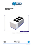
6.2.2
Typical evaporator water piping connection
PR ESSU R E
G AU G E
VIBR ATIO N
ELIM IN ATO R
W ATER
STR AIN ER
VIBR ATIO N
ELIM IN ATO R
G ATE
VALV E
FLO W
SW ITC H
BALA N C IN G
VALV E
FLO W
G ATE
VALV E
FLO W
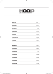
The water flow rate through the evaporator changes according to the unit model and must be between the minimum and maximum values shown
in the evaporator pressure drop table below.
Avoid varying the water flow rate through the evaporator while compressor(s) is/are operating.
Bar
1,00
1 PN P 160÷180
2
0,90
6
2
5
3 PN P 200÷220
9
0,80
PN P 190
4 PN P 310÷330
8
3
0,70
LOSS OF HEAD
20
5 PN P 360÷405
6 PN P 420÷440
1
0,60
7 PN P 470÷500
4
7
8 PN P 530÷560
0,50
9 PN P 250÷280
0,40
0,30
0,20
0,10
WATER FLOW
m3/h
0,00
0
50
100
150
200
250
Additional technical data can be found in the Technical Catalogue.
6.3
Antifreeze protection
ATTENTION
The unit operates with water outlet temperature between -10 ÷15°C.
Even if the minimum working ambient temperature is above 0°C it is possible for the refrigerator - during stoppages in the cold seasons - to find
itself in an environment with a temperature below 0°C. In these cases, if the refrigerator is not emptied, antifreeze (ethylene glycol) must be
added in the following percentages to prevent the formation of ice:
Min. ambient temp.
[°C]
Ethylene glycol
[% in volume]
<0
10
-5
15
-10
20
-15
30
-20
35
PN P 160÷560
The data in this manual are not binding and may be changed by the manufacturer without notice. Reproduction of this manual, even partial, is strictly prohibited.
MANUALE DI ISTRUZIONE E MANUTENZIONE
Plumbing connections
Depending on the cooled water outlet temperature, antifreeze (ethylene glycol) must be added in the following percentages to prevent the
formation of ice:
Min. water outlet temperature
[°C]
Ethylene glycol
[% in volume]
<5
15
0
20
-5
25
-10
35
-15
40
-20
45
Additional technical data can be found in the Technical Catalogue.
ATTENTION
When the temperature is lower than or equal to 3°C is necessary to add ethylene glycol.
PN P 160÷560
The data in this manual are not binding and may be changed by the manufacturer without notice. Reproduction of this manual, even partial, is strictly prohibited.
21
22
MANUALE DI ISTRUZIONE E MANUTENZIONE
Electrical connections
CHAPTER 7
ELECTRICAL CONNECTIONS
7.1
Electrical circuit
See the enclosed wiring diagrams.
7.2
Electrical connections
Check that the power supply voltage and frequency match the requirements of the unit as shown on the unit data plate and within the tolerances
given in the wiring diagram.
Ensure that the electrical installation complies with local wiring and safety regulations.
For the entry of the electrical cables into the machine, used the provided plates as suggested in the
drawing below.
To check that the machine is correctly connected to the power supply, see chapter
"8.2 Start
up" .
At the beginning of the power cable:
1.it must be guaranteed a protection from the direct contacts with a protection rating of IP2X or
IPXXB at least;
2.It must be installed a safety device which:
prevents short-circuiting or overloading of the supply and all other unprotected cables of the plant;
(refer to the information indicated on the wiring diagram)
limits the 15 kA peak short circuit current to its own nominal cut-off power when the short circuit
current at the operation point is higher than 10 kA effective;
protects against indirect contacts on the unit, such as short-circuiting between the phase and protection circuit, by cutting off the
supply automatically (see IEC 364 - HD 384, CEI 64-8); To do this use a differential switch (with cut-in nominal differential power
of 0.03 A)
protects against phase failure where the electrical supply is three-phase.
For dimensioning the protection circuit, reference should be made to all the data specified in the wiring diagram (max. absorption, pickup
currents, cable section).
ATTENTION
In the event of failure of one cooling circuit it must be cut off electrically to run the machine with the other circuit only.
To cut off one or other cooling circuit separately, use the switches in the power board (see annexed wiring plan).
7.3
Protection rating
The protection rating of the whole machine is IP54.
PN P 160÷560
The data in this manual are not binding and may be changed by the manufacturer without notice. Reproduction of this manual, even partial, is strictly prohibited.
MANUALE DI ISTRUZIONE E MANUTENZIONE
Unit operations
CHAPTER 8
UNIT OPERATIONS
8.1
Precautions during operation
Operation must be carried out by competent personnel under a qualified supervisor.
Never remove or tamper with the safety devices, guards or insulation materials fitted to the unit or auxiliary equipment.
When main switch is turned on, lethal voltages are present in the electrical circuits and extreme caution must be exercised whenever it is
necessary to carry out any work on the electrical system.
The first time the machine is started after several days’ stoppage, turn on the casing resistance of every compressor at least 4 hours
before pressing the ON/OFF button (see
"8.2 Start up" ).
Do not exceed the liquid flow to be cooled specified in chapter
8.2
" Installation" .
Start up
ATTENTION
Before starting up these units be sure that all personnel have read and understood the "
Safety" section of this manual.
1. Check that the machine's on/off valves are open.
2. If the hydraulic circuit is of the closed type, check that an expansion tank has been installed with an adequate capacity.
3. Check that the ambient temperature is within the limits indicated on the machine data plate.
4.Check that the main switch is in the OFF position (“O”).
5.Check that the power supply voltage is correct.
6.Power the machine by means of the supply line protection device.
7.Turn the machine main switch ON (“I”). LED buttons on the control panel indicate that the machine is
powered.
8.Models without pump: check that water flows through the evaporator.
9. Check that the outlet cocks of the compressors are open.
10. Press the g+h button on the board. The pump, if installed, starts immediately. After the delay set on the electronic board the
cooling compressors can start. The first time the machine is started after several days’ stoppage, turn the main switch to the ON
position (“I”) and wait at least 4 hours before starting the machine by means of the ON/OFF (g+h) button on the board.
To switch off press g+h buttons again.
11. Check that the rotation direction of the pump, if present, is correct. If not, stop the machine and invert two phases in the supply
terminals of the power board. Check that the fan rotation direction is correct (if a pump has been installed and its rotation direction
is correct, the fan rotation direction should also be correct). The cooling air must enter the refrigerators from the finned coils of the
condensers. If necessary, invert two phases to reverse the rotation direction.
12. The unit is now ready to work.
13. If with the first start-up, there is a high ambient temperature and the temperature of the water in the hydraulic circuit is much
higher than the working value (e.g. 25-30°C) this means that the refrigerator starts up overloaded with the consequence of possible
protection device tripping. To reduce this overload, a refrigerator outlet valve can be gradually (but not totally!) closed to reduce
the flow of water passing through it. Open the valve as the water temperature in the hydraulic circuit reaches the working value.
PN P 160÷560
The data in this manual are not binding and may be changed by the manufacturer without notice. Reproduction of this manual, even partial, is strictly prohibited.
23
24
MANUALE DI ISTRUZIONE E MANUTENZIONE
Unit operations
8.3
Operation
The machine operates in completely automatic mode.
It is not necessary to turn it off when there is no thermal load as it turns off automatically when the preset water-inlet temperature is reached.
ATTENTION
Never exceed the water flow values specified in the table in chapter " Installation" .
Never turn off the water circuit circulation pump before turning off the machine.
Units without pump: before turning on the machine turn on the circulation pump.
PN P 160÷560
The data in this manual are not binding and may be changed by the manufacturer without notice. Reproduction of this manual, even partial, is strictly prohibited.
MANUALE DI ISTRUZIONE E MANUTENZIONE
Adjustment and control
CHAPTER 9
ADJUSTMENT AND CONTROL
9.1
pCO terminal unit
9.1.1
Terminal buttons
The functions of pGD1 terminal buttons are explained here below:
pGD1 buttons
Function
j
If pressed once it is utilized to check if in the pCO there is any alarm on.
After removing the alarm cause, a second pressure of this button resets the signalling.
l
If pressed once it allows to enter DIRECT loop.
If pressed for more than 5" it allows to enter the configuration modality (password needed).
k
Utilized to return from the various menus to the main displaying mask.
Utilized to scroll the various masks of a loop when the cursor is in HOME position.
Utilized to increase or decrease the value of a numeric field (configuration).
Utilized to scroll the various sub-sections of a mask.
It allows to scroll the list of sub-sections of a loop.
If pressed during unit normal operation or when unit is in stand-by, it shows the programme version, the programme code, the
BIOS and BOOT versions and the mask with the indication of unit status.
g or f
Utilized to move the cursor on the various adjustable fields of a mask.
It allows the access to the selected programming sub-section.
Sometimes it is used to confirm the operation.
h
9.1.2
Function of combined buttons
pGD1 buttons
Function
g+h
When the unit is on, if pressed together they switch on and off the unit.
f+h
When the unit is on, if pressed together they access the masks of other units (only when modular function is enabled).
l+j+g
When the unit is on, keep pressed l + j buttons and press many times g button to increase the contrast.
l+j+f
When the unit is on, keep pressed l + j buttons and press many times f button to decrease the contrast.
g+f+h
When the unit is on, if pressed together they are utilized to address the pGD1/network.
PN P 160÷560
The data in this manual are not binding and may be changed by the manufacturer without notice. Reproduction of this manual, even partial, is strictly prohibited.
25
26
MANUALE DI ISTRUZIONE E MANUTENZIONE
Adjustment and control
9.1.3
Terminal leds
pGD1 Led
Function
l
On when the menu loop is displayed, with or without password.
j
On when an alarm is present.
g-f-h-k
9.2
On when the terminal is powered.
Tecnical characteristics
The electronic control allows to:
•
•
•
•
regulate the evaporator water inlet/outlet temperature with proportional logic, neutral zone or PID;
check and dispaly the evaporator water inlet and outlet temperatures;
check and dispaly the evaporating and condensing pressures;
manage the automatic rotation of the compressors starting sequences (when there are more compressors) to reduce the working
time of each compressor;
• set the weekly programming;
• display more than 135 alarm messages, as:
condensing high pressure alarm;
evaporating low pressure alarm;
antifreeze alarm on the evaporator water outlet;
compressor and eventual pump damaged alarm;
the water that flows through the evaporator is not enough;
water inlet/outlet high temperature alarm;
the refrigerator and the single compressor have exceeded the programmed number of working hours before maintenance;
minimum/maximum rating alarm, phase sequence not correct and rating lack of balance that exceeds the set value.
If enabled, the control enables interaction of units of the same type via the pLAN network. This case is known as a modular system where a
Master unit manages other Slave units.
A contact is available to remote the signalling of a general alarm. It is also available an outlet with proportional signal to control the inverter
pump.
9.3
pCO terminal display
The pCO terminal display is used to show information concerning unit status and to change the values of programmable parameters.
The top left corner of the display represents the cursor HOME position.
The MAIN mask is displayed the first time the electronic controller is switched on.
To return to the main mask during pCO programming, simply press button k as many times as necessary.
NOTE
If no operations are carried out for 5 minutes the unit returns automatically to the MAIN mask.
The contents of the display are shown in
"Fig. 1 Main mask":
Set date and time
HOME position
Temperature
measured by
8BUFS5FNQFSBUVSF
&WBQPS*/«$
8BUFS5FNQFSBUVSF
&WBQPS065«$
6OJU0GG
Unit status
indicator
inlet probe
Temperature
measured by
outlet probe
Fig. 1 MAIN
MASK
PN P 160÷560
The data in this manual are not binding and may be changed by the manufacturer without notice. Reproduction of this manual, even partial, is strictly prohibited.
MANUALE DI ISTRUZIONE E MANUTENZIONE
Adjustment and control
9.3.1
Display/signalling masks
In addition to the main mask described above, the electronic controller also offers a series of display or signalling masks. These masks are
displayed after a period of transition during which no button of the pGD1 is pressed.
PO
°$
This mask will be displayed after 10 minutes in which no pGD1
buttons are pressed.
This mask shows date, time and unit ON status at the top left;
the bottom left of the mask shows the temperature control
value, set-point, and current time.
4&510*/5°$
PGG
This mask, which is similar to the previous one, appears with
the unit is OFF.
°$
4&510*/5°$
PGG
This mask, similar to the previous one, is displayed when
an alarm trips (the bell symbol flashes).
Press button j to display the relative alarm (see Chapter 19
“Alarms management“).
°$
4&510*/5°$
The screensaver mask will be displayed after approximately
20 minutes in which no pGD1 buttons are pressed.
9.4
Unit start-up and stop
When the installation and electrical connections have been carried out, operate on the unit general switch-breaker (on the electrical panel)
putting it in ON position.
The terminal unit is correctly connected to the power supply line when the LED of the buttonsf, g, h and k light up.
After the net has stabilized, the main mask will appear.
NOTE
Every time the unit is switched on by means of the main switch-breaker, it is recommended to leave the unit in STAND-BY for any second to
allow the pCO net to stabilize.
Press the buttons h+g of the pGD1 terminal to switch on the unit and consequently start the setting procedure.
When the unit is on it will displayed the message “ 6OJU0O”.
To switch off the unit press h+g buttons on pGD1 terminal.
The unit will switch off and the message “6OJU0GG” will be displayed.
9.4.1
Automatic restart
If the electrical supply is cut-off, when the power returns the machine starts in ON, if the mode was ON and remains in OFF, if the mode was
OFF (function to be enabled).
9.5
Access to the programming
The electronic control is furnished with two main menus:
1. FREE menu (PASSWORD NOT needed) see
"9.5.1 How to modify a parameter in “Free Menu”"
It can be accessed by pressing and releasing l.
2. PASSWORD menu (PASSWORD needed) see
"9.5.2 How to modify a parameter of “Password Menu”"
It can be accessed by pressing and releasing for 5 sec. l.
PN P 160÷560
The data in this manual are not binding and may be changed by the manufacturer without notice. Reproduction of this manual, even partial, is strictly prohibited.
27
28
MANUALE DI ISTRUZIONE E MANUTENZIONE
Adjustment and control
9.5.1
How to modify a parameter in “Free Menu”
1. Press and release l on the terminal to access the loop mask (free menu):
2. It is possible to scroll the different loops using g or f
button on the terminal.
i/o
SET-POINT
user
3. After selecting the desired loop (e.g. “ User”) press h
to access the mask of this loop (HOME position).
It will be possible to scroll the masks using g or f
set-point
USER
i/o
button.
4. Find the parameter that has to be modified, press h to move the cursor on the first parameter of the displayed mask.
5. Modify the value using g or f.
6. Press again the button h to confirm the value.
If in the mask there is more than one parameter the cursor will move to the following one and, when the last one is reached, the
cursor will return to HOME position.
7. To move to another mask of the loop press g or f, when the cursor is in HOME position.
To access a new loop press once the button k and it will be possible to go back to the loop mask.
8. To go back to the MAIN mask press twice k button on the terminal.
9.5.2
How to modify a parameter of “Password Menu”
1. Enable the password menu pressing for 5 sec. the button l on the terminal;
2. The password is required;
3. Insert the correct password using g or f on the
terminal;
Insert
Password:
000000
4. Press the button h again to confirm the password.
5. If the password is wrong, the message “>>WRONG
PASSWORD<< ” will appear, it will be necessary to
insert it again.
If the password is right, the various scrolling loops will
be accessed;
It is possible to scroll the loops using g or f button on
the terminal.
The loops will be displayed in groups of three.
unit config.
modularity
DRIVER
worked hours
manual function
compressors
fans
condensing valve
unloading
recovery
freecooling
pumps
alarms
antifreeze
clock
historials
supervisor
special functions
other settings
PN P 160÷560
The data in this manual are not binding and may be changed by the manufacturer without notice. Reproduction of this manual, even partial, is strictly prohibited.
MANUALE DI ISTRUZIONE E MANUTENZIONE
Adjustment and control
6. Find the desired loop (e.g. “worked hours ”) press
h to access the mask of the loop (HOME position).
To scroll the masks use g or f.
driver
WORKED HOURS
manual function
compressorS
ATTENTION
The access to the loops depends on the password .
7. Follow the same procedure described on paragraph
"9.5.1 How to modify a parameter in “Free Menu”" from point 4. to
point 8.
ATTENTION
All the parameter masks are grouped by LOOP they belong to and are joined to an alpha-numeric reference.
9.6
Main settings
9.6.1
H o w t o s e t t he l a n g u a g e
The pCO allows to choose the language of the masks.
The available languages are: Italian, English, German, French and Spanish.
1. To access “User” loop follow the same procedure
"9.5.1 How to modify a
parameter in “Free Menu”".
described in chapter
set-point
USER
i/o
2. Press g or f to reach the mask with the languages;
3. Press h: the cursor starts flashing under the current
language;
4. Choose the language using the button g or f;
5. Press h to confirm the language;
The display automatically returns to show the main mask
-BOHVBHF64
6TFE
&OHMJTI
translated on the language selected and, consequently, also
all the other masks.
ATTENTION
Each unit is delivered ready to work, therefore all the control parameters have been already set during the testing operation and it isn’t
necessary to modify them.
On particular cases it is possible to modify the set point values by following the instruction indicated below.
9.6.2
How to modify the setpoint value
1. Follow the same procedure described in chapter
"9.5.1 How to
modify a parameter in “Free Menu”" .
2. Select the Set-Point loop and press h on the terminal.
3. The first mask of the loop Setpoint will be visualized, press the button
g or f to visualize the mask displayed on the side;
i/o
SET-POINT
user
Setpoint
SP002
Summer
000.0 C
Second Setpoint
Summer
000.0 C
PN P 160÷560
The data in this manual are not binding and may be changed by the manufacturer without notice. Reproduction of this manual, even partial, is strictly prohibited.
29
30
MANUALE DI ISTRUZIONE E MANUTENZIONE
Adjustment and control
4. Press h on the terminal:
Setpoint
SP002
Summer
000.0 C
Second Setpoint
Summer
000.0 C
the cursor will go to the field “ Summer Setpoint ”.
NOTE
The second setpoint will be visualized only if it has been enabled.
5. Use the button g or f to change the value;
6. Press h to store the new value;
7. Press twice the button k to go back to the Main mask.
ATTENTION
Modify the SETPOINT only if necessary, making sure that they are neither too low nor too high.
DANGER
A Summer Setpoint which is too low may cause ice formation so that antifreeze must be added.
Generally the differential values must not be too low.
If the differential value must be modified, consider also the delays for compressor starts and stops.
9.7
Setpoint management
The pCO electronic control can manage the setpoint in five different ways:
•
•
•
•
•
9.8
fixed setpoint;
compensated setpoint;
double setpoint;
adjustable setpoint by daily bands;
setpoint by analogue input.
Fixed set-point
The pCO controller manages water temperature control according to a fixed set-point and differential that cannot be altered by external agents or
actions.
9.9
Compensated set-point
The compensated set-point is measured on the basis of the ambient air temperature detected by probe (-BAT1) and the values of the “4FU
QPJOU4VNNFS$PNQFOTBUJPO” and “.BYJNVN$PNQFOTBUJPO7BMVF” parameters. The following diagram shows the set-point trend
on the basis of the various parameter settings: Diagram with positive “$PNQFOTBUJPO%JGGFSFOUJBM”;
$BMDVMBUFE
4FUQPJOU
.BYJNVN
$PNQFOTBUJPO
$)*--&3
4FUQPJOU
$PNQFOTBUJPO
4UBSU
$PNQFOTBUJPO
%JGGFSFOUJBM
"NCJFOUBJS
5FNQFSBUVSF
PN P 160÷560
The data in this manual are not binding and may be changed by the manufacturer without notice. Reproduction of this manual, even partial, is strictly prohibited.
MANUALE DI ISTRUZIONE E MANUTENZIONE
Adjustment and control
Diagram with negative “$PNQFOTBUJPO%JGGFSFOUJBM”;
$BMDVMBUFE
4FUQPJOU
.BYJNVN
$PNQFOTBUJPO
$)*--&3
4FUQPJOU
$PNQFOTBUJPO
4UBSU
9.10
$PNQFOTBUJPO
%JGGFSFOUJBM
"NCJFOUBJS
5FNQFSBUVSF
Dual set-point
A second operating set-point can be programmed, with selection between the two set-points performed by switching the electronic board digital
input (see electrical diagram).
9.11
Time band variable set-point
With time-band variable set-point operation four time-bands can be programmed with different set-points. Once the programmed time has been
reached, the controller changes the unit set-point according to the value programmed for the time-band in question.
9.12
Variable set-point from digital input (Multifunction)
The set-point is variable in accordance with the temperature value detected by a probe set as “analog input 4÷20mA”.
The following diagram shows the operating logic:
7BSJBCMF
TFUQPJOU
.BYJNVN
TFUQPJOU
.JOJNVN
TFUQPJOU
N"
9.13
N"
"OBMPHJOQVU
÷ N"
Proportional Integral Derivative temperature
regulation (PID)
The P+I+D temperature regulation considers:
•
the difference between the temperature value detected by the probe and the preset value: Proportional value P.
• the time during which the temperature value remains stable through the Integral Error I ;
• the speed of the using water temperature variation through the Derivative D value.
The addition of these parameters generates the Temperature Regulation Variable, and according to it the compressor are switched on or off.
9.14
Neutral Zone temperature regulation
When the temperature measured by the probe will be lower than the setpoint value (so under the Neutral Zone) it will be required the stopping of
one or more compressors (the compressors consecutive stopping will be done with a pre-fixed delay time) until the temperature measured will
return within the limits of the Neutral Zone.
When the temperature measured by the probe will be higher than the setpoint + differential value (so above the Neutral Zone), it will be required
the starting of one or more compressors (the compressors consecutive starting will be done with a pre-fixed delay time) until the temperature
measured will return within the limits of the Neutral Zone.
PN P 160÷560
The data in this manual are not binding and may be changed by the manufacturer without notice. Reproduction of this manual, even partial, is strictly prohibited.
31
MANUALE DI ISTRUZIONE E MANUTENZIONE
Adjustment and control
The graphic of the Neutral Zone Logic explains how the increasing or decreasing requirement of “cold” fixes the compressors starting or
stopping, following the logic of the Neutral Zone.
WATER TEMPERATURE
SET+DIFF.
NEUTRAL ZONE
SET
TIME
COMPRESSORS
STATUS
CIRCUIT 2
{
{
CIRCUIT 1
32
Compr. 4 ON
Compr. 3 ON
Compr. 2 ON
Compr. 1 ON
Compr. OFF
Starts delay
9.15
Stops delay
TIME
Antifreeze control
The anti-freeze control depends on the temperature measured at the evaporator outlet (-BEWOT probe).
When the temperature decreases below the preset antifreeze threshold the pCO will produce an alarm which will block the unit.
It will persist until the temperature increases and reaches a value higher than setpoint + differential.
9.16
Supervision System
The pCO can manage the following supervision protocols:
•
•
•
•
•
9.17
9.17.1
CAREL
MODBUS
GSM
DIRECT MODEM (Rs 232)
LONWORKS
Alarms signals
A l a rm s d is p l a y i n g
During unit operation, some alarm conditions could happen. Depending on their danger they could be controlled by pCO by means of a simple
signal or by means of the partial / complete block of the unit.
When an alarm occurs, on the pCO display appears “ENABLED ALARM” and the red led of the button j lights up.
Press the button j on the terminal to visualize the alarm mask, consisting of 2 alarm LOOPS:
• Unit alarms,
• Driver alarms;
On the right corner it will be visualized the number of active alarm.
Press h to move the cursor in the desired LOOP, then use the button g or f on the terminal to
scroll the other alarm messages.
N Active Alarms:
Unit Alarms
Driver Alarms
000
The alarm loops are enabled only if there is an alarm. They are enabled when the loop indication
is in capital letters and the symbol
b is displayed.
Use the alarm list to identify the alarm displayed and to have more information (see paragraph "13.3
9.18
Alarms masks" ).
Alarms reset
When the alarm cause has been resolved, if it was of automatic reset type the unit will automatically return to normal operation.
If the alarm was of manual reset type, press j button for more times until reaching the reset.
The message “No Alarm Active ” will appear on the display if the button j is pressed without any alarm on.
To return to the main mask press k button.
PN P 160÷560
The data in this manual are not binding and may be changed by the manufacturer without notice. Reproduction of this manual, even partial, is strictly prohibited.
MANUALE DI ISTRUZIONE E MANUTENZIONE
Other components
9.19
Compressors management
The compressors are started-up with Part-Winding logic.
There are other function for compressors management:
•
•
•
•
•
9.20
Compressors capacity control according to the thermal request
Proportional Integral Derivative control (PID) and Neutral Zone
Step Less compressors control, by means of relays it increases of decreases the compressor power
Compressors rotation, in order to maintain all compressors with the same number of working hours
Pump-down, it controls the stopping of compressors in order to avoid the presence of liquid at compressor suction.
Compresors unloading procedure
One or more capacity control steps are disabled, reducing the condenser thermal power. They are enabled when the max. ambient temperature is
reached or when the condenser thermal power is too high caused by the water inlet temperature too high.
9.21
Compressor integral protection (PI)
This protection consists of three or six thermostatic sensors, each sunk in the winding of one motor phase; they are connected together in series
and their terminals are taken to the outside.
This system ensures complete protection against most of the problems which can give rise to burning of the windings.
When it trips, it is necessary to find and eliminate the cause; then it is necessary to energize and de-energize the unit operating on the circuit
breaker.
9.22
Circulation pump
When the machine is turned on by means of h+g buttons the pump starts.
When the machine is turned off by means of h+g buttons it remains on for the preset delay.
The pump stops only when some alarms trip.
CHAPTER 10
OTHER COMPONENTS
10.1
Electronic thermostatic valve (optional)
The units can be furnished with electronic thermostatic valves.
The electronic thermostatic valve is controlled by the electronic board (DRIVER) which manages the informations sent by the pressure and
temperature transducers.
The electronic board allows to control the overheating and to optimize the unit capacity.
To verify the type of valve installed see the alpha-numeric string code.
10.2
Forced ventilation of the electrical board
The circulation fan trips when the temperature in the electrical board exceeds about 40°C. The units working with a temperature of -20 °C are
equipped with heating resistances, which are installed inside the electronic board in order to protect its components.With the option -20 the fan is
activated in tandem with the anti-freeze resistances.
10.3
Antifreeze resistances with -20 function (optional)
Antifreeze resistance kits are option furnished, in alternative to the glycol. They protect the water circuit from ice formation with ambient
temperatures until -20°C. These resistances can be installed only if the fan electronic adjustment is enabled. Not present on HE versions.
10.4
High pressure switches (HP)
They assure a supplementary protection of electromechanical type in addition to the protection furnished by the pCO transducers.
They are installed to monitor the refrigerant compressor discharge pressure and prevents it increasing to levels dangerous to the operation of the
unit and people within the vicinity.
•
Each unit is furnished with one “Safety” high pressure switch of “manual reset” type.
When it trips, it opens the compressor supply circuit (see wiring diagram).
Then, when the compressor delivery pressure drops below the reset point, it must be manually re-armed and it is possible to start
the machine again by means of the ALARM button of the electronic control.
• Each unit is furnished with a high pressure switch “Type Approved”, associated to each compressor of the refrigerant circuit. It
is of “automatic reset” type.
When it trips, it opens the compressor supply circuit (see wiring diagram).
Then, when the compressor delivery pressure drops below the reset point, it automatically re-arms and it is possible to start the
machine again by means of the ALARM button of the electronic control.
The pressure switches HP should be screwed to the cooling circuit piping using a SCHRAEDER valve (with needle) which prevent leakage
during the pressure switch replacement.
For a correct operation of the unit it is recommended that the reset values of the pressure switches are the ones indicated in the table below:
COMPONENT
REFRIGERANT
HP-Safety
High pressure switch
HP Type Approved
High pressure switch
TRIP
bar
°C
R134a
18.5
R134a
18
RESET
°F
bar
°C
66.4
14.5
56.5
65.4
13
52.4
°F
PN P 160÷560
The data in this manual are not binding and may be changed by the manufacturer without notice. Reproduction of this manual, even partial, is strictly prohibited.
33
34
MANUALE DI ISTRUZIONE E MANUTENZIONE
Other components
10.5
Pressure and temperature transducers
The units are furnished with two types of transducers:
•
•
10.6
pressure transducers, directly powered by the electronic control
temperature transducers, of Negative Temperature Coefficient (NTC) resistitive type
Function of transducers
Pressure transducers (P) and temperature transducers (T) are connected to specific inputs on the pCO board.
Each connected transducer has a specific function and is identified with letter B and a number.
This table identifies transducer types and indicates their function.
TRANSDUCER
-BHP1
-BHP3
-BEWIT
-BEWOT1
-BEWOT2
-BLP3
-BAT1
-BDT1
-BDT3
connected to analog input
B1
B2
B3
B4
B5
B6
B7
B8
B9
B10
TRANSDUCER FUNCTION
P
P
T
T
T
P
P
T
T
T
X
X
LOW PRESSURE
X(1)
X(3)
PUMP-DOWN
X(1)
X(3)
X
X
-BDT2
-BDT4
B9
B10
P
P
X
X
BOARD
-BLP1
MASTER
EVAPORATOR WATER
INLET
X
EVAPORATOR WATER
OUTLET
TANK WATER OUTLET
HIGH PRESSURE
X(1)
X(3)
UNLOADING
X(1)
X(3)
STEP CONTROL FANS
X(1)
X(3)
SPEED CONTROL FANS
X(1)
X(3)
X
ANTI-FREEZE ALARM
X
X
AMBIENT TEMPERATURE
X
COMPRESSOR DISCHARGE
TEMPERATURE
TRANSDUCER
-BHP2
-BHP4
-BAT2
connected to analog input
B1
B2
B3
TRANSDUCER FUNCTION
P
P
T
-BEWOT
BOARD
-BLP2
-BLP4
SLAVE
B5
B6
B7
P
P
P
LOW PRESSURE
X(2)
X(4)
PUMP-DOWN
X(2)
X(4)
EVAPORATOR WATER
INLET
B8
X
EVAPORATOR WATER
OUTLET
X
TANK WATER OUTLET
HIGH PRESSURE
B4
X
X(2)
X(4)
UNLOADING
X(2)
X(4)
STEP CONTROL FANS
X(2)
X(4)
SPEED CONTROL FANS
X(2)
X(4)
ANTI-FREEZE ALARM
AMBIENT TEMPERATURE
X
COMPRESSOR DISCHARGE
TEMPERATURE
Table 1 USING THE TRANSDUCERS
(1)USED ONLY FOR READINGS RELATIVE TO CIRCUIT 1 OPERATION
(2)USED ONLY FOR READINGS RELATIVE TO CIRCUIT 2 OPERATION
(3)USED ONLY FOR READINGS RELATIVE TO CIRCUIT 3 OPERATION
(4)USED ONLY FOR READINGS RELATIVE TO CIRCUIT 4 OPERATION
ATTENTION
The number of transducers connected to the board depends on the type of unit and is established in design phase.
PN P 160÷560
The data in this manual are not binding and may be changed by the manufacturer without notice. Reproduction of this manual, even partial, is strictly prohibited.
MANUALE DI ISTRUZIONE E MANUTENZIONE
Other components
10.7
Pressure transducers
The units are equipped with an high and low pressure transducer for each cooling circuit. Through the compressors inlet/outlet pressure value
they manage the unit operation according to the pressure setpoint value set in the pCO. Through the parameter measurement, it is possible to
control, for each circuit, the following functions:
•
•
•
•
•
•
If the pressure
high pressure alarm;
low pressure alarm;
unloading for high pressure;
pump-down for low pressure (not enabled);
fan management;
high and low pressure value measurement.
of one circuit is higher or lower than the preset value an alarm could trip and stop the unit, the fans start up/switch off, one or
more compressors stop with a variable delay.
10.8
Fan groups
The high pressure transducers connected to the pCO board can be used to manage the fans in three ways:
•
•
•
10.8.1
by Step Control
by Speed Control
by Speed Medium Control
Step Control
The pCO activates step control of the fans on the basis of the pressure values measured by the high pressure transducers on the refrigerant circuit
pipes. Condensation control is provided by two steps for each group. The activation of one fans step corresponds to starting of one subgroup
composed of several fans. The fans of each refrigerant circuit are started in groups in such a way as to achieve gradual connection with several
steps on the basis of the condensing pressure.
"Fig. 2 Fans step activation logic" describes the operating logic of 2-step control:
FAN STATUS
OFF
STEP 2
ON
OFF
STEP 1
ON
OFF
}
}
4FU
%JGG1
4FU
%JGG
VALUE DETECTED
BY HIGH PRESSURE
TRANSDUCERS
BHP
Fig. 2 FANS STEP ACTIVATION LOGIC
In the event of step regulation, the fans of each circuit are pregressively started-up, according to the condensation pressure.
Fan step management logic: the first fans to start are 12-3, then 7-8-9, 4-5-6 and, at the end, 10-11-12. In
1
QE
3
2
7
5
every circuit all coils must work at the same time.
circuit 2
circuit 1
4
9
8
6
10
11
12
Logic of fan activation in step mode: fans 1-2 are
started first, followed by fans 3-5 and 4-6.
5
QE
3
circuit 1
1
6
4
circuit 2
2
PN P 160÷560
The data in this manual are not binding and may be changed by the manufacturer without notice. Reproduction of this manual, even partial, is strictly prohibited.
35
36
MANUALE DI ISTRUZIONE E MANUTENZIONE
Other components
10.8.2
Variable speed control
Fan speed can be modulated using a phase cut-off regulator controlled by the pCO.
On the units each group of fans can work at a different speed according to the pressure value detected by the corresponding pressure transducer
(-BHP transducers).
In normal operation the fans are stopped when pressure read by the high pressure transducers (-BHP) is lower than the set-point value, or when
the last compressor is stopped.
"Fig. 3 Fans activation logic with speed control" describes the operating logic of the fan speed control system.
FAN SPEED
maximum speed
%
fans ON
minimum speed
%
fans OFF
}
Set
Fig. 3 FANS
10.9
Diff
Set+Diff
VALUE DETECTED BY
THE HIGH PRESSURE
TRANSDUCERS
ACTIVATION LOGIC WITH SPEED CONTROL
Water differential pressure switch
The machine is provided with a differential pressure switch which measures the water pressure difference between the inlet and outlet manifold
of the evaporator. When the pressure switch measures a
the machine after the preset delay. When the
'p lower than 50 mbar (250 mmH2O), it sends an alarm signal to the board which stops
'p returns above 50 mbar it is possible to restart the machine pressing ALARM button. It is
necessary that this situation is isolated and limited in the time.
PN P 160÷560
The data in this manual are not binding and may be changed by the manufacturer without notice. Reproduction of this manual, even partial, is strictly prohibited.
MANUALE DI ISTRUZIONE E MANUTENZIONE
Conduction and maintenance
CHAPTER 11
CONDUCTION AND MAINTENANCE
11.1
Maintenance and repair precautions
Maintenance, overhaul and repair work must be carried out by competent personnel under a qualified supervisor.
The non-insulated surfaces of the components of the cooling circuits inside the compressor
compartment can be at very high temperatures when the machine is in operation and for some
minutes after it is turned off.
11.2
Maintenance operations
ATTENTION
Before proceeding with the installation and maintenance of these units be sure that all personnel concerned have read and understood the
"
Safety" chapter of this manual.
These units will give many years of trouble-free service if they are properly maintained and serviced.
Because there are sharp edges in the rear and internal compartment that can cut and harm,
the maintenance technicians must take care to protect themselves from accidental contact
with these edges during work inside the compartment.
11.2.1
A c c e s s t o t he i n s i d e e l e c t r i c a l b o a r d o f t h e m a c h i n e
ATTENTION
The access to the electronic board is allowed only if the unit is off.
To gain access to the components of the electrical
board, turn the main switch/circuit breaker to the
open “O” position and open the closing bolts with
the provided key.
For models with panels to the compressor compartment:
Remove the bottom side panels using a screwdriver
to remove the screws.
Given the presence of sharp and cutting edges
in the rear and internal compartment, the
maintenance technician must protect himself
from accidental contact during work inside the
compartment.
PN P 160÷560
The data in this manual are not binding and may be changed by the manufacturer without notice. Reproduction of this manual, even partial, is strictly prohibited.
37
38
MANUALE DI ISTRUZIONE E MANUTENZIONE
Conduction and maintenance
11.2.2
Emptying of the evaporator
There is a cock at the rear of the evaporator to be
used for draining it. This operation is necessary
when the machine is stopped and it has no
antifreeze resistance, and the ambient
temperature reaches the freezing point of the
water.
11.2.3
Maintenance Schedule
OPERATION
1
day
Check control panel display for any alarm signals.
¡
Check that the water outlet temperature is within the envisaged range.
¡
1
month
Check that the water inlet temperature is lower than the value used for
selecting the refrigerator.
¡
Check that the difference between the pump output pressure (if installed) and
intake pressure (measured by a pressure gauge with the pump stopped) is
within the limits envisaged and, in particular, is not lower than the value
corresponding to the maximum flow.
¡
6
months
Check that the liquid indicator is full or with a small stream of bubbles when
the compressor is running.
¡
Check that the unit current absorption is within the data plate values.
¡
Carry out visual inspection of refrigerant circuit, looking out for any
deterioration of the piping or any traces of oil which might indicate a
refrigerant leak.
¡
Check the condition and security of piping connections.
¡
Check the condition and security of wiring and electrical connections.
¡
Using a spanner, check that the connections to the refrigerant compressor
have not slackened.
¡
Check that the ambient air temperature is lower than the value used for
selecting the refrigerator.
Check that the environment is well ventilated.
Check that every fan is turned on automatically. Check that fan operation is
not noisy. Thoroughly clean the fins of the condenser with soft brush and/or
jet of clean compressed air. Check that the grilles of the unit are free from
dirt and any other obstructions.
Clean condenser fins with a mild detergent.
annually
¡
¡
¡
IMPORTANT:
•
•
This plan is based on an average working situation.
In some installations it may be necessary to increase the frequency of maintenance.
PN P 160÷560
The data in this manual are not binding and may be changed by the manufacturer without notice. Reproduction of this manual, even partial, is strictly prohibited.
MANUALE DI ISTRUZIONE E MANUTENZIONE
Trouble shooting
CHAPTER 12
TROUBLE SHOOTING
PROBLEM
A
Water outlet temperature
BEWOT higher than the
expected value.
CAUSE
A1
A2
A3
A4
A5
A6
A7
B
Low pressure drop (water
pressure) at the pump outlet
(if installed).
B1
B2
B3
C
The refrigerator is obstructed
and the water doesn’t flow.
C1
Water flow too high.
Thermal load too high (water
flow) x (input temperature water outlet) = Thermal load.
Ambient temperature too
high.
Condenser fins dirty.
Front surface of the
condenser obstructed.
The fans rotate in the wrong
direction.
No refrigerant fluid in the
plant.
Water flow too high. Wrong
working of the pump (high
flow, low discharge head,
high absorption).
See point C . Before ice
obstructs the whole
evaporator, there is an
increase in the pressure
drop.
Evaporator obstructed
because of dirt transported
by the water to be cooled.
Set point too low so that the
water freezes.
SYMPTOM
A1.1
Difference between BEWIT
and BEWOT lower than
5°C with both circuits on.
A2.1
• Temperature BEWOT greater
than expected value;
• alarm high water outlet
temperature trips.
A3.1
See
A2.1
See
A2.1
See
A2.1
See
A2.1
A4.1
REMEDY
Increase the pressure drop in the
water circuit (e.g.: by partially
closing a pump outlet cock).
Restore the thermal load to
within the preset limits.
Restore the ambient temperature
to within the preset limits.
Clean the condenser fins.
A5.1
A6.1
A7.1
• See
A2.1 ;
• low evaporation pressure;
• a lot of bubbles in the liquid
indicator.
B1.1
• Possible increase in the outlet
temperature BEWOT (see
A2.1 );
Free the front surface of the
condenser.
Invert the position of 2 of the 3
power supply phases.
Get a refrigerator technician to
check for leaks and eliminate
them.
Fill the plant.
Reduce water flow within design
limits, for example by partially
closing a pump outlet cock.
• with pump installed on the
machine: pressure difference,
read on the machine pressure
gauge, too low with pump
stopped and pump running.
B2.1
See point
B3.1
C.
High water temperature
difference between inlet
and outlet.
C1.1
• Water doesn’t flow;
• the water differential pressure
switch alarm trips;
• intake pressure too low.
See point
C.
Depending on the type of dirt:
• clean the evaporator by
running a detergent solution
which is not aggressive for
steel and copper;
• run a high water flow against
the stream.
Install a filter upstream from the
refrigerator.
Choose between:
• raise the set point;
• add an appropriate % of
ethylene glycol (antifreeze)
(see " Installation" ).
E The formation of ice can
irremediably damage the
refrigerator.
PN P 160÷560
The data in this manual are not binding and may be changed by the manufacturer without notice. Reproduction of this manual, even partial, is strictly prohibited.
39
40
MANUALE DI ISTRUZIONE E MANUTENZIONE
Trouble shooting
PROBLEM
D
High pressure switch or the
high pressure alarm trips.
CAUSE
D1
D2
One or more fans do not
work.
Ambient air temperature too
high.
SYMPTOM
D1.1
•
•
•
•
See problem;
refrigerant compressor stops;
ALARM led lights on;
main alarm relay tripped.
D2.1
• Ambient air temperature
higher than maximum
permitted value;
• see
D3
Recirculation of warm air due
to incorrect installation
location.
• Condenser cooling air
temperature higher than the
permitted value;
• see
D4
See
A4.
See
A5.
D5
D6
D7
E
F
Low pressure switch or low
pressure alarm trips.
Compressor overload alarm
trips.
E1
F1
F2
F3
F4
F5
G
Digital display and all LEDs
off although main switch On
(“I”).
G1
G2
Ambient temperature high
combined with incorrect fan
rotation.
Thermal load = (water flow)
x (inlet temperature - water
outlet) too high.
No refrigerant fluid in the
plant (see also A7 ).
Thermal load = (water flow)
x (inlet temperature - water
outlet) too high in
combination with high
ambient temperature.
Thermal load = (water flow)
x (inlet temperature - water
outlet) too high combined
with a shortage of refrigerant
(also see A7 ).
Problems to the refrigerant
circuit (thermostatic valve).
Problems to the power
supply.
Compressor blocked.
Control board fuse blown.
Power supply fluctuations or
'spikes'.
Abnormal power
consumption by one or more
of the control board
components.
D1.1 .
D3.1
D1.1 .
D4.1
See
D1.1 .
See
D1.1 .
D5.1
D6.1
• The fan blows air across the
condenser coil instead of
drawing it across;
• refrigerant compressor stops.
D7.1
• Water outlet temperature too
high;
• refrigerant compressor stops;
• main alarm relay tripped.
E1.1
• Refrigerant compressor
stops;
• main alarm relay tripped.
F1.1
• See problem;
• main alarm relay tripped;
• refrigerant compressor stops.
F2.1
Repair or replace the fan. Verify
the heat protection of the fan/s.
Reduce ambient temperature
within design limits, for example
by increasing local ventilation.
Press ALARM button to run the
unit.
Change the position of the unit or
the position of any adjacent
obstructions to avoid
recirculation.
Press ALARM button to run the
unit.
Clean the condenser fins. Press
ALARM button to run the unit.
Remove obstruction from the
frontal side of the condenser.
Press ALARM button to run the
unit.
Invert the position of two phases
of the power supply to the fan
(see chap. "8.2 Start up" ).
Reduce the thermal load to
within preset limits.
Press ALARM button to run the
unit.
Call a qualified refrigeration
engineer to check for leaks and
replenish refrigerant charge.
Check that the temperature of
the cooled water and of the
ambient air are within the preset
limits (see chap. "
Performances" ).
Restore the load within the
preset limits.
Wait a few minutes before
turning on again.
See
F1.1
Call a qualified refrigeration
engineer to check for leaks and
replenish refrigerant charge.
See
F1.1
Call a qualified refrigeration
engineer to check the
thermostatic valve and to replace
it, if necessary.
See
F1.1
See
F1.1
F3.1
F4.1
F5.1
G1.1
REMEDY
Despite presence of power
at the input terminals, the
digital display and all LEDs
remain unlit.
G2.1
See
G1.1 .
Call an electrician to check the
power supply of the unit.
Find out and eliminate the causes
of anomalies to the power supply
line.
Call a qualified refrigeration
engineer to check the
compressor and to replace it, if
necessary.
Replace the fuse.
Provide cleaner power supply to
the unit.
Replace the fuse and, if
necessary, replace the control
board.
PN P 160÷560
The data in this manual are not binding and may be changed by the manufacturer without notice. Reproduction of this manual, even partial, is strictly prohibited.
MANUALE DI ISTRUZIONE E MANUTENZIONE
Trouble shooting
PROBLEM
H
I
J
K
Alarm “Water inlet or outlet
probe damaged/
unconnected” trips.
Low water inlet temperature
alarm trips.
High water inlet temperature
alarm trips.
Low water outlet
temperature alarm trips.
CAUSE
H1
I1
J1
K1
K2
K3
L
M
High water outlet
temperature alarm trips.
Fan(s) overload alarm trips
(thermal protection of fans).
L1
M1
M2
N
Oil pressure switch alarm
trips.
N1
N2
O
Alarm “Eprom damaged”
trips.
O1
BEWIT, BEWOT sensor in
open or in short circuit.
The value set in the
parameter of the appropriate
alarm threshold is higher
than value measured by
BEWIT probe.
See points A1 and A7 .
The value set in the
appropriate parameter is
lower than value measured
by BEWIT probe.
The value set as LOW WATER
OUTLET TEMPERATURE alarm
threshold is higher than
value measured by BEWOT
probe.
Water flow too low.
Temperature SET POINT
value is too low.
See points A1 and A7 .
The value set as HIGH
WATER OUTLET
TEMPERATURE alarm
threshold is lower than value
measured by BEWOT probe.
The thermal protection of
one of the fans has tripped
because the temperature of
the air expelled is very high.
See point F4 . The motor of
one of the fans is blocked or
risks seizing.
Lack of oil in the compressor
casing.
Various startings-up without
oil pre-heating resistance.
Board microprocessor
initialising error.
SYMPTOM
H1.1
• See problem;
• main alarm relay tripped.
I1.1
• See problem;
• main alarm relay tripped.
J1.1
• See problem;
• main alarm relay tripped.
K1.1
• See problem;
• the compressor stops and
restarts when the alarm
threshold is exceed;
• main alarm relay tripped.
K2.1
K1.1 .
See
K1.1 .
• See problem;
• main alarm relay tripped.
M1.1
See problem;
main alarm relay tripped;
refrigerant compressor stops;
ALARM led lights up.
M2.1
See problem;
main alarm relay tripped;
refrigerant compressor stops;
ALARM led lights up;
operation in one of the fans is
noisy.
N1.1
•
•
•
•
See problem;
main alarm relay tripped;
refrigerant compressor stops;
ALARM led lights up.
N2.1
See
O1.1
Identify and remove the cause
which provoked BEWIT
temperature decreasing to a
value lower than the preset one.
Identify and remove the cause
which provoked BEWIT
temperature increasing to a
value higher than the preset one.
Identify and remove the cause
which provoked BEWOT
temperature decreasing to a
value lower than the preset one.
Increase the SET POINT value.
L1.1
•
•
•
•
•
Check that the temperature
sensors are correctly connected
to the control board terminals
and that the cable is undamaged.
If necessary replace the
temperature sensors.
Increase the water flow.
See
K3.1
•
•
•
•
REMEDY
N1.1 .
Alarm signal and unit
blocked.
Identify and remove the cause
which provoked BEWOT
temperature increasing to a
value higher than the preset one.
Check that the ambient air
temperature is within the preset
limits.
Identify and check the damaged
fan and replace it if necessary.
Check that no improper operation
has been carried out; e.g.,
starting the compressor without
a flow of cooled water.
Have the plant checked by a
refrigeration engineer and add oil
in the compressor until it is seen
in the oil indicator.
ATTENTION:
The oil must be the same as the
one already present.
To pre-heat the oil, at the first
starting-up after various days of
stopping, after putting the main
switch in the close position (“I”),
wait 4 hours at least before
starting-up the unit with ON/OFF
button of the board.
(see chap. "8.2 Start up" ).
Turn off and turn on the unit. If
this doesn’t solve the problem,
contact the nearest service
centre.
PN P 160÷560
The data in this manual are not binding and may be changed by the manufacturer without notice. Reproduction of this manual, even partial, is strictly prohibited.
41
42
MANUALE DI ISTRUZIONE E MANUTENZIONE
Trouble shooting
PROBLEM
P
Pump overload alarm trips.
CAUSE
P1
The pump's thermal
protection device has tripped
because the water flow is too
high.
SYMPTOM
P1.1
• See problem;
• main alarm relay tripped;
• the refrigerant compressor
and pump stop;
• ALARM led lights up;
• the pressure difference read
on the machine gauge with
the pump stopped and pump
running is lower than the
available head with maximum
pump flow (see chap. "
REMEDY
Reset the thermal protection
device.
Increase the pressure drop in the
hydraulic circuit, for example by
partially closing the pump output
valve.
Plumbing connections".
P2
P3
P4
Q
Water differential pressure
switch alarm trips.
Q1
Q2
Q3
The grille through which the
pump cooling air passes is
obstructed.
The pump is defective.
Incorrect pump rotation
direction.
See point F4 . The pump
doesn’t work.
The water circuit is
obstructed outside the
machine.
Water inlet and outlet
connections inverted.
P2.1
• See problem;
• main alarm relay tripped;
• the refrigerant compressor
and pump stop;
• ALARM led lights up.
P3.1
• See problem;
• main alarm relay tripped;
• the refrigerant compressor
and pump stop;
• ALARM led lights up;
• the current absorbed by the
pump is higher than the
nominal rating;
• the pump may be noisy.
P4.1
See
P3.1.
Q1.1
Reset the thermal protection
device.
Free the grille.
Reset the thermal protection
device.
Replace the pump.
Invert the position of two phases
of the pump power supply (see
chap. "8.2 Start up" ).
Check the state of the pump.
• See problem;
• main alarm relay tripped;
• the refrigerant compressor
and pump stop;
• ALARM led lights up.
Q2.1
Check the external water circuit.
• See problem;
• main alarm relay tripped;
• the refrigerant compressor
and pump stop;
• ALARM led lights up.
Q3.1
• See problem;
• main alarm relay tripped;
• the refrigerant compressor
and pump stop;
• ALARM led lights up.
Provide to connect correctly the
water inlet and outlet
connections (see annexed overall
dimension drawings).
PN P 160÷560
The data in this manual are not binding and may be changed by the manufacturer without notice. Reproduction of this manual, even partial, is strictly prohibited.
MANUALE DI ISTRUZIONE E MANUTENZIONE
Alarms management
CHAPTER 13
ALARMS MANAGEMENT
13.1
Alarms signals
13.1.1
Alarms displaying
During unit operation, some alarm conditions could happen. Depending on their danger they could be controlled by pCO by means of a simple
signal or by means of the partial / complete block of the unit.
When an alarm occurs, on the pCO display appears “ENABLED ALARM” and the red led of the button j lights up.
Press the button j on the terminal to visualize the first alarm mask.
On the right corner it will be visualized the number of active alarm.
/|"DUJWF"MBSNT
"MBSN
Use the button g or f on the terminal to run the other alarm messages.
'MBTI.FNPSZ
NBMGVODUJPO
Use the alarm list to identify the alarm displayed and to have more information (see paragraph "13.3
13.2
Alarms masks" ).
Alarms reset
When the alarm cause has been resolved, if it was of automatic reset type the unit will automatically return to normal operation.
If the alarm was of manual reset type, press j button for more times until reaching the reset.
The message “ No Alarm Active” will appear on the display if the button j is pressed without any alarm on.
To return to the main mask press k button.
13.3
Ref.
Alarms masks
Masks
Reset
Controller action
Input
Notes
No active alarm mask.
ALARM000
/P"MBSN
"DUJWF
ALARM001
aut.
Complete stop of
the unit and of the
pump
---
The pCO memory is irreparably
damaged.
Try to restart the unit.
If the alarm repeats, call an
authorised service centre.
aut.
Complete stop of
the unit and of the
pump
---
The Clock board of pCO is
irreparably damaged.
Try to restart the unit.
If the alarm repeats, call an
authorised service centre.
manual
Complete stop of
the unit and of the
pump.
ID3
Master
Board
Insufficient water flow throughout
the evaporator (differential
pressure switch).
manual
Complete stop of
the unit and of the
pump.
ID3
Master
Board
Insufficient water level in the
tank.
When the water level in the tank
is restored, the alarm is
automatically reset.
/«"DUJWF"MBSNT
"MBSN
'MBTINFNPSZ
NBMGVODUJPO
ALARM002
/«"DUJWF"MBSNT
"MBSN
$MPDLEBNBHFE
ALARM003
/«"DUJWF"MBSNT
"MBSN
8BUFS%JGGFSFOU
1SFTTVSFTXJUDI
ALARM004
/«"DUJWF"MBSNT
"MBSN
5BOL
-FWFM
PN P 160÷560
The data in this manual are not binding and may be changed by the manufacturer without notice. Reproduction of this manual, even partial, is strictly prohibited.
43
44
MANUALE DI ISTRUZIONE E MANUTENZIONE
Alarms management
Ref.
Masks
ALARM005
Reset
Controller action
manual
Complete stop of
the unit and of the
pump.
ID2 Slave
Board
Pump 1 overload
manual
Complete stop of
the unit and of the
pump.
ID3 Slave
Board
Pump 2 overload
manual
Circuit 1 fans and
compressors stop.
ID12
Master
Board
This alarm occurs only in the
event of fans variable speed
regulation, when the regulator
has anomalies during its
operation or in the event of
circuit 1 fans overload.
manual
Circuit 2 fans and
compressors stop.
ID12
Slave
Board
This alarm occurs only in the
event of fans variable speed
regulation, when the regulator
has anomalies during its
operation or in the event of
circuit 2 fans overload.
manual
Circuit 3 fans and
compressors stop.
ID13
Master
Board
This alarm occurs only in the
event of fans variable speed
regulation, when the regulator
has anomalies during its
operation or in the event of
circuit 3 fans overload.
manual
Circuit 4 fans and
compressors stop.
ID13
Slave
Board
This alarm occurs only in the
event of fans variable speed
regulation, when the regulator
has anomalies during its
operation or in the event of
circuit 4 fans overload.
manual
The compressor 1
stops
ID6
Master
Board
Compressor 1 overload
manual
The compressor 1
stops
ID7
Master
Board
Internal protection of compressor
1 tripping
manual
The compressor 1
stops
ID5
Master
Board
The oil level sensor of compressor
1 measures an insufficient oil
level
/«"DUJWF"MBSNT
"MBSN
&WBQPSBUPSQVNQ
PWFSMPBE
ALARM006
/«"DUJWF"MBSNT
"MBSN
&WBQPSBUPSQVNQ
PWFSMPBE
ALARM007
/«"DUJWF"MBSNT
"MBSN
'BOPWFSMPBE
SFHVMBUPSGBVMU
VOJU
ALARM008
/«"DUJWF"MBSNT
"MBSN
'BOPWFSMPBE
SFHVMBUPSGBVMU
VOJU
ALARM009
/«"DUJWF"MBSNT
"MBSN
'BOPWFSMPBE
SFHVMBUPSGBVMU
VOJU
ALARM010
/«"DUJWF"MBSNT
"MBSN
'BOPWFSMPBE
SFHVMBUPSGBVMU
VOJU
ALARM011
/«"DUJWF"MBSNT
"MBSN
$PNQSFTTPS
UIFSNBMQSPUFDUJPO
ALARM012
/«"DUJWF"MBSNT
"MBSN
*OUFSOBM1SPUFDUJPO
$PNQSFTTPS
ALARM013
/«"DUJWF"MBSNT
"MBSN
0JM1SFTTVSF4XJUDI
$PNQSFTTPS
Input
Notes
PN P 160÷560
The data in this manual are not binding and may be changed by the manufacturer without notice. Reproduction of this manual, even partial, is strictly prohibited.
MANUALE DI ISTRUZIONE E MANUTENZIONE
Alarms management
Ref.
Masks
ALARM014
Reset
Controller action
manual
The compressor 1
stops
ID8
Master
Board
Anomaly during part-winding
procedure at compressor 1
starting-up
manual
The compressor 2
stops
ID6 Slave
Board
Compressor 2 overload
manual
The compressor 2
stops
ID7 Slave
Board
Internal protection of compressor
2 tripping
manual
The compressor 2
stops
ID5
Master
Board
The oil level sensor of compressor
2 measures an insufficient oil
level
manual
The compressor 2
stops
ID8 Slave
Board
Anomaly during part-winding
procedure at compressor 2
starting-up
manual
The compressor 3
stops
ID10
Master
Board
Compressor 3 overload
manual
The compressor 3
stops
ID11
Master
Board
Internal protection of compressor
3 tripping
manual
The compressor 3
stops
ID9
Master
Board
The oil level sensor of compressor
3 measures an insufficient oil
level
manual
The compressor 3
stops
ID8
Master
Board
Anomaly during part-winding
procedure at compressor 3
starting-up
/«"DUJWF"MBSNT
"MBSN
$PNQSFTTPS
DPSSFDUTUBSU
ALARM015
/«"DUJWF"MBSNT
"MBSN
$PNQSFTTPS
UIFSNBMQSPUFDUJPO
ALARM016
/«"DUJWF"MBSNT
"MBSN
*OUFSOBM1SPUFDUJPO
$PNQSFTTPS
ALARM017
/«"DUJWF"MBSNT
"MBSN
0JM1SFTTVSF4XJUDI
$PNQSFTTPS
ALARM018
/«"DUJWF"MBSNT
"MBSN
$PNQSFTTPS
DPSSFDUTUBSU
ALARM019
/«"DUJWF"MBSNT
"MBSN
$PNQSFTTPS
UIFSNBMQSPUFDUJPO
ALARM020
/«"DUJWF"MBSNT
"MBSN
*OUFSOBM1SPUFDUJPO
$PNQSFTTPS
ALARM021
/«"DUJWF"MBSNT
"MBSN
0JM1SFTTVSF4XJUDI
$PNQSFTTPS
ALARM022
/«"DUJWF"MBSNT
"MBSN
$PNQSFTTPS
DPSSFDUTUBSU
Input
Notes
PN P 160÷560
The data in this manual are not binding and may be changed by the manufacturer without notice. Reproduction of this manual, even partial, is strictly prohibited.
45
46
MANUALE DI ISTRUZIONE E MANUTENZIONE
Alarms management
Ref.
Masks
ALARM023
Reset
Controller action
manual
The compressor 4
stops
ID10
Slave
Board
Compressor 4 overload
manual
The compressor 4
stops
ID11
Slave
Board
Internal protection of compressor
4 tripping
manual
The compressor 4
stops
ID9 Slave
Board
The oil level sensor of compressor
4 measures an insufficient oil
level
manual
The compressor 4
stops
ID8 Slave
Board
Anomaly during part-winding
procedure at compressor 4
starting-up
manual
Circuit 1 stops
---
Error in the pump-down
procedure in circuit 1: min.
pressure level not reached during
the pump-down delay time
manual
Circuit 2 stops
---
Error in the pump-down
procedure in circuit 2: min.
pressure level not reached during
the pump-down delay time
manual
Circuit 3 stops
---
Error in the pump-down
procedure in circuit 3: min.
pressure level not reached during
the pump-down delay time
manual
Circuit 4 stops
---
Error in the pump-down
procedure in circuit 4: min.
pressure level not reached during
the pump-down delay time
aut.
Complete stop of
the unit and of the
pump
ID1 Slave
Board
Anomalies due to the not correct
phase sequence of the electrical
supply.
When the electrical supply is
restored the alarm must be
manually reset.
/«"DUJWF"MBSNT
"MBSN
$PNQSFTTPS
UIFSNBMQSPUFDUJPO
ALARM024
/«"DUJWF"MBSNT
"MBSN
*OUFSOBM1SPUFDUJPO
$PNQSFTTPS
ALARM025
/«"DUJWF"MBSNT
"MBSN
0JM1SFTTVSF4XJUDI
$PNQSFTTPS
ALARM026
/«"DUJWF"MBSNT
"MBSN
$PNQSFTTPS
DPSSFDUTUBSU
ALARM027
Input
/«"DUJWF"MBSNT
"MBSN
8SPOHQVNQEPXO
QSPDFEVSF
DJSDVJU
ALARM028
/«"DUJWF"MBSNT
"MBSN
8SPOHQVNQEPXO
QSPDFEVSF
DJSDVJU
ALARM029
/«"DUJWF"MBSNT
"MBSN
8SPOHQVNQEPXO
QSPDFEVSF
DJSDVJU
ALARM030
/«"DUJWF"MBSNT
"MBSN
8SPOHQVNQEPXO
QSPDFEVSF
DJSDVJU
ALARM031
/«"DUJWF"MBSNT
"MBSN
5ISFFQIBTF
QPXFSTVQQMZ
GBVMUT
Notes
PN P 160÷560
The data in this manual are not binding and may be changed by the manufacturer without notice. Reproduction of this manual, even partial, is strictly prohibited.
MANUALE DI ISTRUZIONE E MANUTENZIONE
Alarms management
Ref.
Masks
ALARM032
Reset
Controller action
Circuit 1 stops
B1 Master The probe measures an out-ofBoard
range value: it may be damaged,
not connected or short-circuited.
See Chapter 10 “Pressure
transducers“.
manual
Circuit 1 stops
B6 Master The probe measures an out-ofBoard
range value: it may be damaged,
not connected or short-circuited.
See Chapter 10 “Pressure and
temperature transducers“.
manual
Circuit 2 stops
B1 Slave
Board
The probe measures an out-ofrange value: it may be damaged,
not connected or short-circuited.
See Chapter 10 “Pressure and
temperature transducers“.
manual
Circuit 2 stops
B6 Slave
Board
The probe measures an out-ofrange value: it may be damaged,
not connected or short-circuited.
See Chapter 10 “Pressure and
temperature transducers“.
manual
Circuit 3 stops
B2 Master The probe measures an out-ofBoard
range value: it may be damaged,
not connected or short-circuited.
See Chapter 10 “Pressure and
temperature transducers“.
manual
Circuit 3 stops
B7 Master The probe measures an out-ofBoard
range value: it may be damaged,
not connected or short-circuited.
See Chapter 10 “Pressure and
temperature transducers“.
manual
Circuit 4 stops
B2 Slave
Board
The probe measures an out-ofrange value: it may be damaged,
not connected or short-circuited.
See Chapter 10 “Pressure and
temperature transducers“.
manual
Circuit 4 stops
B7
Slave
Board
The probe measures an out-ofrange value: it may be damaged,
not connected or short-circuited.
See Chapter 10 “Pressure and
temperature transducers“.
Aut.
Stop of the unit, the B3
pump remains on.
Master
Board
/«"DUJWF"MBSNT
"MBSN
#-1QSFTTVSF
USBOTEVDFS
EBNBHFEPSEJTDPOO
ALARM034
/«"DUJWF"MBSNT
"MBSN
#)1QSFTTVSF
USBOTEVDFS
EBNBHFEPSEJTDPOO
ALARM035
/«"DUJWF"MBSNT
"MBSN
#-1QSFTTVSF
USBOTEVDFS
EBNBHFEPSEJTDPOO
ALARM036
/«"DUJWF"MBSNT
"MBSN
#)1QSFTTVSF
USBOTEVDFS
EBNBHFEPSEJTDPOO
ALARM037
/«"DUJWF"MBSNT
"MBSN
#-1QSFTTVSF
USBOTEVDFS
EBNBHFEPSEJTDPOO
ALARM038
/«"DUJWF"MBSNT
"MBSN
#)1QSFTTVSF
USBOTEVDFS
EBNBHFEPSEJTDPOO
ALARM039
/«"DUJWF"MBSNT
"MBSN
#-1QSFTTVSF
USBOTEVDFS
EBNBHFEPSEJTDPOO
ALARM040
/«"DUJWF"MBSNT
"MBSN
#&8*5UFNQFSBUVSF
QSPCF
EBNBHFEPSEJTDPOO
Notes
manual
/«"DUJWF"MBSNT
"MBSN
#)1QSFTTVSF
USBOTEVDFS
EBNBHFEPSEJTDPOO
ALARM033
Input
The probe measures an out-ofrange value: it may be damaged,
not connected or short-circuited.
See Chapter 10 “Pressure and
temperature transducers“.
PN P 160÷560
The data in this manual are not binding and may be changed by the manufacturer without notice. Reproduction of this manual, even partial, is strictly prohibited.
47
48
MANUALE DI ISTRUZIONE E MANUTENZIONE
Alarms management
Ref.
Masks
ALARM041
Reset
The probe measures an out-ofrange value: it may be damaged,
not connected or short-circuited.
See Chapter 10 “Pressure and
temperature transducers“.
Aut.
Stop of the unit, the B5
pump remains on.
Master
Board
The probe measures an out-ofrange value: it may be damaged,
not connected or short-circuited.
See Chapter 10 “Pressure and
temperature transducers“.
Aut.
Stop of the unit, the B5
pump remains on
Slave
and the antifreeze
Board
resistance switch
on
The probe measures an out-ofrange value: it may be damaged,
not connected or short-circuited.
See Chapter 10 “Pressure and
temperature transducers“.
Aut.
Stop of the unit, the B8
pump remains on.
Master
Board
The probe measures an out-ofrange value: it may be damaged,
not connected or short-circuited.
See Chapter 10 “Pressure and
temperature transducers“.
Aut.
Stop of the unit, the B3
pump remains on.
Slave
Board
The probe measures an out-ofrange value: it may be damaged,
not connected or short-circuited.
See Chapter 10 “Pressure and
temperature transducers“.
manual
Stop of the unit, the B3
pump remains on.
Master
Board
The temperature value measured
by the probe is equal to or higher
than the alarm threshold.
See Chapter 10 “Pressure and
temperature transducers“ and
Ref. AL001.
Aut.
Stop of the unit, the B3
pump remains on.
Master
Board
The temperature value measured
by the probe is equal to or lower
than the alarm threshold.
See Chapter 10 “Pressure and
temperature transducers“ and
Ref. AL001.
Aut.
Stop of the unit, the B4
pump remains on.
Master
Board
The temperature value measured
by the probe is equal to or higher
than the alarm threshold.
See Chapter 10 “Pressure and
temperature transducers“ and
Ref. AL002.
Aut.
Stop of the unit, the B4
pump remains on.
Master
Board
The temperature value measured
by the probe is equal to or lower
than the alarm threshold.
See Chapter 10 “Pressure and
temperature transducers“ and
Ref. AL002.
/«"DUJWF"MBSNT
"MBSN
#5805UFNQFSBUVSF
QSPCF
EBNBHFEPSEJTDPOO
ALARM044
/«"DUJWF"MBSNT
"MBSN
#"5UFNQFSBUVSF
QSPCF
EBNBHFEPSEJTDPOO
ALARM045
/«"DUJWF"MBSNT
"MBSN
#"5UFNQFSBUVSF
QSPCF
EBNBHFEPSEJTDPOO
ALARM053
/«"DUJWF"MBSNT
"MBSN
&WBQPSBUPS
XBUFSJOMFU
IJHIUFNQFSBUVSF
ALARM054
/«"DUJWF"MBSNT
"MBSN
&WBQPSBUPS
XBUFSJOMFU
MPXUFNQFSBUVSF
ALARM055
/«"DUJWF"MBSNT
"MBSN
&WBQPSBUPS
XBUFSPVUMFU
IJHIUFNQFSBUVSF
ALARM056
/«"DUJWF"MBSNT
"MBSN
&WBQPSBUPS
XBUFSPVUMFU
MPXUFNQFSBUVSF
Notes
Stop of the unit, the B4
pump remains on.
Master
Board
/«"DUJWF"MBSNT
"MBSN
#&805UFNQFSBUVSF
QSPCF
EBNBHFEPSEJTDPOO
ALARM043
Input
Aut.
/«"DUJWF"MBSNT
"MBSN
#&805UFNQFSBUVSF
QSPCF
EBNBHFEPSEJTDPOO
ALARM042
Controller action
PN P 160÷560
The data in this manual are not binding and may be changed by the manufacturer without notice. Reproduction of this manual, even partial, is strictly prohibited.
MANUALE DI ISTRUZIONE E MANUTENZIONE
Alarms management
Ref.
Masks
ALARM057
Reset
The temperature value measured
by the probe is equal to or higher
than the alarm threshold.
See Chapter 10 “Pressure and
temperature transducers“ and
Ref. AL002.
Aut.
Stop of the unit, the B5
pump remains on.
Master
Board
The temperature value measured
by the probe is equal to or lower
than the alarm threshold.
See Chapter 10 “Pressure and
temperature transducers“ and
Ref. AL002.
Aut.
Stop of the unit, the B5
pump remains on.
Slave
Board
The temperature value measured
by the probe is equal to or higher
than the alarm threshold.
See Chapter 10 “Pressure and
temperature transducers“ and
Ref. AL002.
Aut.
Stop of the unit, the B5
pump remains on.
Slave
Board
The temperature value measured
by the probe is equal to or lower
than the alarm threshold.
See Chapter 10 “Pressure and
temperature transducers“ and
Ref. AL003.
manual
Circuit 1 stop
B1
Master
Board
The pressure value measured by
the high pressure transducer of
circuit 1 is equal or higher than
the alarm threshold.
See Chapter 10 “Pressure and
temperature transducers“ and
Ref. AL005.
manual
Circuit 1 stop
Id14
Master
Board
The pressure value in circuit 1 is
equal or higher than the set-point
of the pressure switch.
manual
Circuit 1 stop
B6 Master The pressure value measured by
Board
the low pressure transducer of
circuit 1 is equal or higher than
the alarm threshold.
See Chapter 10 “Pressure and
temperature transducers“ and
Ref. AL004.
manual
Circuit 2 stop
B2
Slave
Board
The pressure value measured by
the high pressure transducer of
circuit 2 is equal or higher than
the alarm threshold.
See Chapter 10 “Pressure and
temperature transducers“ and
Ref. AL005.
manual
Circuit 2 stop
ID14
Slave
Board
The pressure value in circuit 2 is
equal or higher than the set-point
of the pressure switch.
/«"DUJWF"MBSNT
"MBSN
8BUFSPVUMFU
IJHIUFNQFSBUVSF
ALARM060
/«"DUJWF"MBSNT
"MBSN
8BUFSPVUMFU
MPXUFNQFSBUVSF
ALARM071
/«"DUJWF"MBSNT
"MBSN
)JHIQSFTTVSF
DJSDVJU
ALARM072
/«"DUJWF"MBSNT
"MBSN
$JSDVJU
IJHIQSFTTVSF
TXJUDI
ALARM073
/«"DUJWF"MBSNT
"MBSN
-PXQSFTTVSF
DJSDVJU
ALARM074
/«"DUJWF"MBSNT
"MBSN
)JHIQSFTTVSF
DJSDVJU
ALARM075
/«"DUJWF"MBSNT
"MBSN
$JSDVJU
IJHIQSFTTVSF
TXJUDI
Notes
Stop of the unit, the B5
pump remains on.
Master
Board
/«"DUJWF"MBSNT
"MBSN
&WBQPSBUPS
XBUFSPVUMFU
MPXUFNQFSBUVSF
ALARM059
Input
Aut.
/«"DUJWF"MBSNT
"MBSN
&WBQPSBUPS
XBUFSPVUMFU
IJHIUFNQFSBUVSF
ALARM058
Controller action
PN P 160÷560
The data in this manual are not binding and may be changed by the manufacturer without notice. Reproduction of this manual, even partial, is strictly prohibited.
49
50
MANUALE DI ISTRUZIONE E MANUTENZIONE
Alarms management
Ref.
Masks
ALARM076
Reset
Controller action
Circuit 2 stop
B6
Slave
Board
The pressure value measured by
the low pressure transducer of
circuit 2 is equal or higher than
the alarm threshold.
See Chapter 10 “Pressure and
temperature transducers“ and
Ref. AL004.
manual
Circuit 3 stop
B2
Master
Board
The pressure value measured by
the high pressure transducer of
circuit 3 is equal or higher than
the alarm threshold.
See Chapter 10 “Pressure and
temperature transducers“ and
Ref. AL005.
manual
Circuit 3 stop
ID15
Master
Board
The pressure value in circuit 3 is
equal or higher than the set-point
of the pressure switch.
manual
Circuit 3 stop
B7
Master
Board
The pressure value measured by
the low pressure transducer of
circuit 3 is equal or higher than
the alarm threshold.
See Chapter 10 “Pressure and
temperature transducers“ and
Ref. AL004.
manual
Circuit 4 stop
B2
Slave
Board
The pressure value measured by
the high pressure transducer of
circuit 4 is equal or higher than
the alarm threshold.
See Chapter 10 “Pressure and
temperature transducers“ and
Ref. AL005.
manual
Circuit 4 stop
ID15
Slave
Board
The pressure value in circuit 4 is
equal or higher than the set-point
of the pressure switch.
manual
Circuit 4 stop
B7
Slave
Board
The pressure value measured by
the low pressure transducer of
circuit 4 is equal or higher than
the alarm threshold.
See Chapter 10 “Pressure and
temperature transducers“ and
Ref. AL004.
aut.
Warning
---
Compressor 1 maintenance is
required.
For further information see
paragraph "9.19 Compressors
/«"DUJWF"MBSNT
"MBSN
)JHIQSFTTVSF
DJSDVJU
ALARM078
/«"DUJWF"MBSNT
"MBSN
$JSDVJU
IJHIQSFTTVSF
TXJUDI
ALARM079
/«"DUJWF"MBSNT
"MBSN
-PXQSFTTVSF
DJSDVJU
ALARM080
/«"DUJWF"MBSNT
"MBSN
)JHIQSFTTVSF
DJSDVJU
ALARM081
/«"DUJWF"MBSNT
"MBSN
$JSDVJU
IJHIQSFTTVSF
TXJUDI
ALARM082
/«"DUJWF"MBSNT
"MBSN
-PXQSFTTVSF
DJSDVJU
ALARM084
/«"DUJWF"MBSNT
"MBSN
$PNQSFTTPS
NBJOUFOBODF
ALARM085
management" .
aut.
/«"DUJWF"MBSNT
"MBSN
$PNQSFTTPS
NBJOUFOBODF
Notes
manual
/«"DUJWF"MBSNT
"MBSN
-PXQSFTTVSF
DJSDVJU
ALARM077
Input
Warning
---
Compressor 2 maintenance is
required.
For further information see
paragraph "9.19 Compressors
management" .
PN P 160÷560
The data in this manual are not binding and may be changed by the manufacturer without notice. Reproduction of this manual, even partial, is strictly prohibited.
MANUALE DI ISTRUZIONE E MANUTENZIONE
Alarms management
Ref.
Masks
ALARM086
Reset
aut.
Controller action
Warning
Input
---
/«"DUJWF"MBSNT
"MBSN
$PNQSFTTPS
NBJOUFOBODF
ALARM087
aut.
Warning
---
aut.
Warning
---
aut.
Warning
---
aut.
Warning
---
Complete unit maintenance is
required.
For further information see
paragraph "9.19 Compressors
management" .
aut.
Complete stop of
the unit
---
The slave board is disconnected
from the net.
aut.
Warning
---
Module not connected to the net.
aut.
Warning
---
Module not connected to the net.
aut.
Warning
---
Module not connected to the net.
/«"DUJWF"MBSNT
"MBSN
4MBWFCPBSE
EJTDPOOFDUFE
ALARM092
Pump 2 maintenance is required.
For further information see
paragraph "9.22 Circulation
pump" .
/«"DUJWF"MBSNT
"MBSN
6OJU
NBJOUFOBODF
ALARM091
Pump 1 maintenance is required.
For further information see
paragraph "9.22 Circulation
pump" .
/«"DUJWF"MBSNT
"MBSN
&WBQPSBUPS
QVNQ
NBJOUFOBODF
ALARM090
Compressor 4 maintenance is
required.
For further information see
paragraph "9.19 Compressors
management" .
/«"DUJWF"MBSNT
"MBSN
&WBQPSBUPS
QVNQ
NBJOUFOBODF
ALARM089
Compressor 3 maintenance is
required.
For further information see
paragraph "9.19 Compressors
management" .
/«"DUJWF"MBSNT
"MBSN
$PNQSFTTPS
NBJOUFOBODF
ALARM088
Notes
/«"DUJWF"MBSNT
"MBSN
.PEVMF
OPUDPOOFDUFE
UPOFUXPSL
ALARM093
/«"DUJWF"MBSNT
"MBSN
.PEVMF
OPUDPOOFDUFE
UPOFUXPSL
ALARM094
/«"DUJWF"MBSNT
"MBSN
.PEVMF
OPUDPOOFDUFE
UPOFUXPSL
PN P 160÷560
The data in this manual are not binding and may be changed by the manufacturer without notice. Reproduction of this manual, even partial, is strictly prohibited.
51
52
MANUALE DI ISTRUZIONE E MANUTENZIONE
Alarms management
Ref.
Masks
ALARM095
Reset
Controller action
Input
Notes
aut.
Warning
---
Module not connected to the net.
aut.
Warning
---
One of the two probes connected
to the Driver of the electronic
thermostatic valve of circuit 1 is
damaged or disconnected.
aut.
Warning
---
The Eeprom of the Driver of the
electronic thermostatic valve of
circuit 1 is damaged or has any
anomaly.
aut.
Warning
---
The step-step motor which
manages the electronic
thermostatic valve of circuit 1 is
damaged or has any anomaly.
aut.
Warning
---
The battery which powers the
Driver of circuit 1 is down or
disconnected.
This alarm appears only if the
battery has been enabled (see
Ref. DR001).
aut.
Warning
---
The pressure probe connected to
the Driver of the electronic
thermostatic valve of circuit 1
measures a too high value.
aut.
Warning
---
The pressure probe connected to
the Driver of the electronic
thermostatic valve of circuit 1
measures a too low value.
aut.
Warning
---
The superheating value
elaborated by the Driver of the
electronic thermostatic valve of
circuit 1 is too low.
aut.
Warning
---
At unit stopping, the Driver which
elaborates the data of the
electronic thermostatic valve of
circuit 1 detects that the valve in
not completely closed.
/«"DUJWF"MBSNT
"MBSN
.PEVMF
OPUDPOOFDUFE
UPOFUXPSL
ALARM096
/«"DUJWF"MBSNT
"MBSN
%SJWFS
QSPCFFSSPS
ALARM097
/«"DUJWF"MBSNT
"MBSN
%SJWFS
FFQSPNFSSPS
ALARM098
/«"DUJWF"MBSNT
"MBSN
%SJWFS
NPUPSTUFQFSSPS
ALARM099
/«"DUJWF"MBSNT
"MBSN
%SJWFS
CBUUFSZFSSPS
ALARM100
/«"DUJWF"MBSNT
"MBSN
%SJWFS
IJHIQSFTTVSF
ALARM101
/«"DUJWF"MBSNT
"MBSN
%SJWFS
MPXQSFTTVSF
ALARM102
/«"DUJWF"MBSNT
"MBSN
%SJWFS
MPXTVQFSIFBU
ALARM103
/«"DUJWF"MBSNT
"MBSN
%SJWFS
WBMWFOPUDMPTFE
XIFOTXJUDIFEPGG
PN P 160÷560
The data in this manual are not binding and may be changed by the manufacturer without notice. Reproduction of this manual, even partial, is strictly prohibited.
MANUALE DI ISTRUZIONE E MANUTENZIONE
Alarms management
Ref.
Masks
ALARM104
Reset
Controller action
Input
aut.
Warning
---
The probe connected to the
Driver of the electronic
thermostatic valve of circuit 1
measures a too high temperature
of the refrigerant fluid suction
during MOP operation.
aut.
Warning
---
The Driver of the electronic
thermostatic valve of circuit 1 is
disconnected or damaged.
aut.
Warning
---
One of the two probes connected
to the Driver of the electronic
thermostatic valve of circuit 2 is
damaged or disconnected.
aut.
Warning
---
The Eeprom of the Driver of the
electronic thermostatic valve of
circuit 2 is damaged or has any
anomaly.
aut.
Warning
---
The step-step motor which
manages the electronic
thermostatic valve of circuit 2 is
damaged or has any anomaly.
aut.
Warning
---
The battery which powers the
Driver of circuit 2 is down or
disconnected.
This alarm appears only if the
battery has been enabled (see
Ref. DR001).
aut.
Warning
---
The pressure probe connected to
the Driver of the electronic
thermostatic valve of circuit 2
measures a too high value.
aut.
Warning
---
The pressure probe connected to
the Driver of the electronic
thermostatic valve of circuit 2
measures a too low value.
aut.
Warning
---
The superheating value
elaborated by the Driver of the
electronic thermostatic valve of
circuit 2 is too low.
/«"DUJWF"MBSNT
"MBSN
%SJWFS
NBYTVDUJPO
UJNFPVUEVSJOH.01
ALARM105
/«"DUJWF"MBSNT
"MBSN
%SJWFS
EJTDPOOFDUFE
ALARM106
/«"DUJWF"MBSNT
"MBSN
%SJWFS
QSPCFFSSPS
ALARM107
/«"DUJWF"MBSNT
"MBSN
%SJWFS
FFQSPNFSSPS
ALARM108
/«"DUJWF"MBSNT
"MBSN
%SJWFS
NPUPSTUFQFSSPS
ALARM109
/«"DUJWF"MBSNT
"MBSN
%SJWFS
CBUUFSZFSSPS
ALARM110
/«"DUJWF"MBSNT
"MBSN
%SJWFS
IJHIQSFTTVSF
ALARM111
/«"DUJWF"MBSNT
"MBSN
%SJWFS
MPXQSFTTVSF
ALARM112
/«"DUJWF"MBSNT
"MBSN
%SJWFS
MPXTVQFSIFBU
Notes
PN P 160÷560
The data in this manual are not binding and may be changed by the manufacturer without notice. Reproduction of this manual, even partial, is strictly prohibited.
53
54
MANUALE DI ISTRUZIONE E MANUTENZIONE
Alarms management
Ref.
Masks
ALARM113
Reset
Controller action
Input
aut.
Warning
---
At unit stopping, the Driver which
elaborates the data of the
electronic thermostatic valve of
circuit 2 detects that the valve in
not completely closed.
aut.
Warning
---
The probe connected to the
Driver of the electronic
thermostatic valve of circuit 2
measures a too high temperature
of the refrigerant fluid suction
during MOP operation.
aut.
Warning
---
The Driver of the electronic
thermostatic valve of circuit 2 is
disconnected or damaged.
aut.
Warning
---
One of the two probes connected
to the Driver of the electronic
thermostatic valve of circuit 3 is
damaged or disconnected.
aut.
Warning
---
The Eeprom of the Driver of the
electronic thermostatic valve of
circuit 3 is damaged or has any
anomaly.
aut.
Warning
---
The step-step motor which
manages the electronic
thermostatic valve of circuit 3 is
damaged or has any anomaly.
aut.
Warning
---
The battery which powers the
Driver of circuit 3 is down or
disconnected.
This alarm appears only if the
battery has been enabled (see
Ref. DR001).
aut.
Warning
---
The pressure probe connected to
the Driver of the electronic
thermostatic valve of circuit 3
measures a too high value.
aut.
Warning
---
The pressure probe connected to
the Driver of the electronic
thermostatic valve of circuit 3
measures a too low value.
/«"DUJWF"MBSNT
"MBSN
%SJWFS
WBMWFOPUDMPTFE
XIFOTXJUDIFEPGG
ALARM114
/«"DUJWF"MBSNT
"MBSN
%SJWFS
NBYTVDUJPO
UJNFPVUEVSJOH.01
ALARM115
/«"DUJWF"MBSNT
"MBSN
%SJWFS
EJTDPOOFDUFE
ALARM116
/«"DUJWF"MBSNT
"MBSN
%SJWFS
QSPCFFSSPS
ALARM117
/«"DUJWF"MBSNT
"MBSN
%SJWFS
FFQSPNFSSPS
ALARM118
/«"DUJWF"MBSNT
"MBSN
%SJWFS
NPUPSTUFQFSSPS
ALARM119
/«"DUJWF"MBSNT
"MBSN
%SJWFS
CBUUFSZFSSPS
ALARM120
/«"DUJWF"MBSNT
"MBSN
%SJWFS
IJHIQSFTTVSF
ALARM121
/«"DUJWF"MBSNT
"MBSN
%SJWFS
MPXQSFTTVSF
Notes
PN P 160÷560
The data in this manual are not binding and may be changed by the manufacturer without notice. Reproduction of this manual, even partial, is strictly prohibited.
MANUALE DI ISTRUZIONE E MANUTENZIONE
Alarms management
Ref.
Masks
ALARM122
Reset
Controller action
Input
aut.
Warning
---
The superheating value
elaborated by the Driver of the
electronic thermostatic valve of
circuit 3 is too low.
aut.
Warning
---
At unit stopping, the Driver which
elaborates the data of the
electronic thermostatic valve of
circuit 3 detects that the valve in
not completely closed.
aut.
Warning
---
The probe connected to the
Driver of the electronic
thermostatic valve of circuit 3
measures a too high temperature
of the refrigerant fluid suction
during MOP operation.
aut.
Warning
---
The Driver of the electronic
thermostatic valve of circuit 3 is
disconnected or damaged.
aut.
Warning
---
One of the two probes connected
to the Driver of the electronic
thermostatic valve of circuit 4 is
damaged or disconnected.
aut.
Warning
---
The Eeprom of the Driver of the
electronic thermostatic valve of
circuit 4 is damaged or has any
anomaly.
aut.
Warning
---
The step-step motor which
manages the electronic
thermostatic valve of circuit 4 is
damaged or has any anomaly.
aut.
Warning
---
The battery which powers the
Driver of circuit 4 is down or
disconnected.
This alarm appears only if the
battery has been enabled (see
Ref. DR001).
aut.
Warning
---
The pressure probe connected to
the Driver of the electronic
thermostatic valve of circuit 4
measures a too high value.
/«"DUJWF"MBSNT
"MBSN
%SJWFS
MPXTVQFSIFBU
ALARM123
/«"DUJWF"MBSNT
"MBSN
%SJWFS
WBMWFOPUDMPTFE
XIFOTXJUDIFEPGG
ALARM124
/«"DUJWF"MBSNT
"MBSN
%SJWFS
NBYTVDUJPO
UJNFPVUEVSJOH.01
ALARM125
/«"DUJWF"MBSNT
"MBSN
%SJWFS
EJTDPOOFDUFE
ALARM126
/«"DUJWF"MBSNT
"MBSN
%SJWFS
QSPCFFSSPS
ALARM127
/«"DUJWF"MBSNT
"MBSN
%SJWFS
FFQSPNFSSPS
ALARM128
/«"DUJWF"MBSNT
"MBSN
%SJWFS
NPUPSTUFQFSSPS
ALARM129
/«"DUJWF"MBSNT
"MBSN
%SJWFS
CBUUFSZFSSPS
ALARM130
/«"DUJWF"MBSNT
"MBSN
%SJWFS
IJHIQSFTTVSF
Notes
PN P 160÷560
The data in this manual are not binding and may be changed by the manufacturer without notice. Reproduction of this manual, even partial, is strictly prohibited.
55
56
MANUALE DI ISTRUZIONE E MANUTENZIONE
Historial
Ref.
Masks
ALARM131
Reset
Controller action
Input
aut.
Warning
---
The pressure probe connected to
the Driver of the electronic
thermostatic valve of circuit 4
measures a too low value.
aut.
Warning
---
The superheating value
elaborated by the Driver of the
electronic thermostatic valve of
circuit 4 is too low.
aut.
Warning
---
At unit stopping, the Driver which
elaborates the data of the
electronic thermostatic valve of
circuit 4 detects that the valve in
not completely closed.
aut.
Warning
---
The probe connected to the
Driver of the electronic
thermostatic valve of circuit 4
measures a too high temperature
of the refrigerant fluid suction
during MOP operation.
aut.
Warning
---
The Driver of the electronic
thermostatic valve of circuit 4 is
disconnected or damaged.
/«"DUJWF"MBSNT
"MBSN
%SJWFS
MPXTVQFSIFBU
ALARM132
/«"DUJWF"MBSNT
"MBSN
%SJWFS
MPXTVQFSIFBU
ALARM133
/«"DUJWF"MBSNT
"MBSN
%SJWFS
WBMWFOPUDMPTFE
XIFOTXJUDIFEPGG
ALARM134
/«"DUJWF"MBSNT
"MBSN
%SJWFS
NBYTVDUJPO
UJNFPVUEVSJOH.01
ALARM135
Notes
/«"DUJWF"MBSNT
"MBSN
%SJWFS
EJTDPOOFDUFE
CHAPTER 14
HISTORIAL
The electronic control has a loop named “historial” (masks Ref. HS000 ), see Chapter 15 “Settings password required“, in which are stored:
1. the last 50 accesses to the User, Service and Manufacturer menu with date and time;
2. the last 50 alarms and:
• alarm code;
• trip date and time;
• -BEWIT, -BEWOT1, -BEWOT2, -BAT1, -BAT2 and -BTWOT temperatures (if present Ref. CU004 ) at tripping;
• low and high pressure at tripping;
• output and input status of MASTER and SLAVE board at tripping;
• fans analogue output status (only if the speed control operation has been enabled) at tripping;
3. status of the electronic thermostatic valve Driver (only if enabled Ref. DR001) at tripping;
4. the last 20 supply alarms (trips and resets).
NOTE
The historial can be resetted only with the password.
PN P 160÷560
The data in this manual are not binding and may be changed by the manufacturer without notice. Reproduction of this manual, even partial, is strictly prohibited.
MANUALE DI ISTRUZIONE E MANUTENZIONE
Settings Tables
CHAPTER 15
Ref.
SETTINGS TABLES
The following tables show the list of all masks which contain
SP00
5 "EKVTUBCMFq41
4FUQPJOU
.JON"
«$
.BYN"
«$
adjustable parameters, important for unit operation.
The absence of any mask on the display is not a malfunction.
ATTENTION
The displaying of some masks depends on the settings of other
masks and also on the unit configuration, decided during design
phase.
All masks are identified by means of a code indicated in Ref. column;
SP00
6 #BOEq41
4FUQPJOU7BSJBUJPO
4UBSUJOHUJNF
5FNQFSBUVSF4FUQPJOU
TVNNFS«$
4FUQPJOU«$
this code will be used in the manual to identify easily any mask.
On Factory setting column are indicated the setting values set during
the unit testing; they are referred only to the unit which has the same
serial number you can find on the label of the first page of this
manual.
DANGER
The modifying of the unit of measurement causes the resetting of
all parameters, they returns to manufacturer values.
SP00
7 #BOEq41
4FUQPJOU7BSJBUJPO
4UBSUJOHUJNF
5FNQFSBUVSF4FUQPJOU
TVNNFS«$
4FUQPJOU«$
The electronic control autimatically converts the parameters value
from a unit of measurement to another one.
S ETTINGS
NO PASSWORD
REQUIRED
SP00
8 #BOEq41
4FUQPJOU7BSJBUJPO
4UBSUJOHUJNF
5FNQFSBUVSF4FUQPJOU
TVNNFS«$
4FUQPJOU«$
ATTENTION
The modifying of the parameters must be carried out by
specialized personnel only.
To modify the following parameters follow the procedure described
in Chapter 9 “How to modify a parameter in “Free Menu”“
Ref.
Factory
Setting
Masks
Masks
Factory
Setting
SP00
9 #BOEq41
4FUQPJOU7BSJBUJPO
4UBSUJOHUJNF
5FNQFSBUVSF4FUQPJOU
TVNNFS«$
4FUQPJOU«$
SET-POINT
SP00
2 4VNNFSq41
TFUQPJOU«$
4FDPOE
4VNNFS4FUQ«$
8JOUFS
4FUQPJOU«$
4FDPOE
4FUQPJOU«$
SP01
0 SP01
1 1*%q41
$POTUBOU3FH
%FBE[POF«$
1SPQPSUJPOBM«$
*OUFHSBMT
%FSJWBUJWFT
3FRVJSFEVQEBUF
JOUFSWBMNT
SP00
3 .BYJNVNq41
DPNQFOTBUJPO
TFUQPJOU«$
4VNNFS$PNQFOTBUJPO
5FNQFSBUVSF4FUQPJOU
"NCJFOU«$
%JGGFSFOU«$
3FHVMBUJPOq41
CBOE
4VNNFS«$
8JOUFS«$
USER
PN P 160÷560
The data in this manual are not binding and may be changed by the manufacturer without notice. Reproduction of this manual, even partial, is strictly prohibited.
57
58
MANUALE DI ISTRUZIONE E MANUTENZIONE
Settings Tables
Ref.
Masks
Factory
Setting
US00
1 -BOHVBHFq64
6TFE &OHMJTI
(FSNBO
6OJUXPSLJOH $IJMMFS
$IJMMFS
US00
2 q64
*OQVUFOBCMF
3FNPUF0O0GG/P
4VNNFS8JOUFS/P
"VUPNBUJDSFTUBSU
BGUFSCMBDLPVU/P
S ETTINGS
6OJU8PSLJOHq0-
IPVSTDPVOUFS
8PSLJOHIPVST
)PVSTSFTFU/P
$PNQSFTTPSq0-
DPVOUT
8PSLJOHIPVST
/«PGTUBSUT
)PVSTSFTFU/P
4UBSUTSFTFU/P
/P
/P
:FT
$PNQSFTTPSq0-
DPVOUT
8PSLJOHIPVST
/«PGTUBSUT
)PVSTSFTFU/P
4UBSUTSFTFU/P
/P
To modify the following parameters follow the procedure described
in Chapter 9 “How to modify a parameter of “Password Menu”“
$PNQSFTTPSq0-
DPVOUT
8PSLJOHIPVST
/«PGTUBSUT
)PVSTSFTFU/P
4UBSUTSFTFU/P
$PNQSFTTPSq0-
DPVOUT
8PSLJOHIPVST
/«PGTUBSUT
)PVSTSFTFU/P
4UBSUTSFTFU/P
Factory
Setting
CU00
2
"EKq$6
#&805
1VNQq0-
DPVOUT
8PSLJOHIPVST
/«PGTUBSUT
)PVSTSFTFU/P
4UBSUTSFTFU/P
/P
/P
/P
/P
OL00
8
1VNQq0-
DPVOUT
8PSLJOHIPVST
/«PGTUBSUT
)PVSTSFTFU/P
4UBSUTSFTFU/P
3B
MODULARITY
DRIVER
WORKED HOURS
/P
/P
OL00
7
CU00
3
°$
CBS
/P
/P
OL00
6
UNIT CONFIGURATION
6OJUq$6
PGNFBTVSFNFOU
5FNQFSBUVSF«$
1SFTTVSFCBS
$POWFSTHBT3
/P
/P
OL00
5
The modifying of the parameters must be carried out by
specialized personnel only, therefore it is necessary to call an
authorized service centre.
1SPCF
4VNNFSXPSLJOH#&8*5
/P
OL00
4
PASSWORD REQUIRED
Masks
Factory
Setting
OL00
2
ATTENTION
Rif
Masks
OL00
3
US00
3 .PEVMFq64
q64
0WFSSJEF
*OQVUFOBCMF
UP-PDBM
3FNPUF0O0GG/P
0QFSBUJPO/P
4VNNFS8JOUFS/P
"VUPNBUJDSFTUBSU
BGUFSCMBDLPVU/P
Rif
/P
/P
MANUAL OPERATION
COMPRESSORS
PUMPS
PN P 160÷560
The data in this manual are not binding and may be changed by the manufacturer without notice. Reproduction of this manual, even partial, is strictly prohibited.
MANUALE DI ISTRUZIONE E MANUTENZIONE
Settings Tables
Rif
Masks
Factory
Setting
FANS
Rif
HS00
0
RECOVERY
ANTIFREEZE
Factory
Setting
Masks
)JTUPSJBM)4
"MBSNT
4VQQMZ
AN002 &WBQPSBUPSq"/
QVNQTPQFSBUJPOXJUI
BOUJGSFF[F
GVODUJPO
/P
4FUQPJOU«$
%JGGFSFOUJBM«$
AN003
&WBQPSBUPSq"/
BOUJGSFF[FIFBUFS
PQFSBUJPO
/P
4UBOECZ
4FUQPJOU«$
%JGGFSFOUJBM«$
"DUJWBU/P
DEFROSTING
ALARMS
CLOCK
WT00
1
$MPDLq85
TFUUJOH
5JNF
%BUF
WT00
2
6OJU0O0GGq85
XFFLMZCBOE
&OBCMJOH/P
4UBSUEBZ
4UPQEBZ
WT00
3
0O0GG%BJMZq85
6OJUCBOE
&OBCMJOH/P
4UBSUJOH
4UPQQJOH
WT00
4
q85
-PXOPJTF
GVODUJPO
&OBCMJOH
%JTBCMJOH
HISTORIAL
HS00
1 q)4
HS00
2 8BUFSq)4
q)4
5FNQFSBUVSF
&WBQ*/«$
&WBQ065«$
&WBQ065«$
0VUMFU«$
HS00
3
"NCJFOUq)4
BJS
"NCJFOU«$
"NCJFOU«$
HS00
4
8BUFSq)4
5FNQFSBUVSF
$POEFOT*/«$
$POEFOT065«$
HS00
5
%JTDIBSHFq)4
UFNQFSBUVSF
$JSDVJU«$
$JSDVJU«$
$JSDVJU«$
$JSDVJU«$
HS00
6
'SFFDPPMJOHq)4
JOMFU
XBUFS
UFNQFSBUVSF«$
PN P 160÷560
The data in this manual are not binding and may be changed by the manufacturer without notice. Reproduction of this manual, even partial, is strictly prohibited.
59
60
MANUALE DI ISTRUZIONE E MANUTENZIONE
Settings Tables
Rif
Masks
Factory
Setting
Rif
Masks
HS00
7
HS01
4
HS00
8
HS01
5
HS00
9
HS01
6
HS01
0
HS01
7
HS01
1
HS01
8
HS01
2
HS02
2
HS01
3
SUPERVISOR
q)4
$JSDVJU
)JHI1SFTTCBS
-PX1SFTTCBS
$JSDVJU
)JHI1SFTTCBS
-PX1SFTTCBS
q)4
$JSDVJU
)JHI1SFTTCBS
-PX1SFTTCBS
$JSDVJU
)JHI1SFTTCBS
-PX1SFTTCBS
.BTUFS#PBSEq)4
%JHJUBM
*OQVUT
§§§§§§§§§§§§§§§§§§
%JHJUBM
0VUQVUT
§§§§§§§§§§§§§§§§§§
4MBWF#PBSEq)4
%JHJUBM
*OQVUT
§§§§§§§§§§§§§§§§§§
%JHJUBM
0VUQVUT
§§§§§§§§§§§§§§§§§§
'BOq)4
0VUQVUT
4UFQ4UFQ
$JSDVJU0''0''
$JSDVJU0''0''
$JSDVJU0''0''
$JSDVJU0''0''
"OBMPHq)4
0VUQVUT
'BO4QFFE3FH
3FHPM7FM7FOU
3FHPM7FM7FOU
3FHPM7FM7FOU
"OBMPHq)4
0VUQVUT
$POEFOTWBMWF
$POEFOTWBMWF
$POEFOTWBMWF
$POEFOTWBMWF
Factory
Setting
"OBMPHq)4
0VUQVUT
'SFFDPPMJOHWBMWF
7FOU'SFFDPPMJOH
%SJWFSq)4
7BMWF
7BMWF1PTJUJPO
4VQFS)FBU«$
4VDU5FNQ«$
%SJWFSq)4
7BMWF
7BMWF1PTJUJPO
4VQFS)FBU«$
4VDU5FNQ«$
%SJWFSq)4
"OBMPHq)4
7BMWF
0VUQVUT
7BMWF1PTJUJPO
'BO4QFFE3FH
3FHPM7FM7FOU
4VQFS)FBU«$
3FHPM7FM7FOU
4VDU5FNQ«$
3FHPM7FM7FOU
%SJWFSq)4
%SJWFSq)4
7BMWF
7BMWF
7BMWF1PTJUJPO
4VQFS)FBU«$
4VDU5FNQ«$
q)4
%SJWFSq)4
7BMWF
7BMWF1PTJUJPO
4VQFS)FBU«$
4VDU5FNQ«$
SU00
1
q46
4VQFSWJTJPO
TZTUFN
FOBCMJOH/P
/P
PN P 160÷560
The data in this manual are not binding and may be changed by the manufacturer without notice. Reproduction of this manual, even partial, is strictly prohibited.
MANUALE DI ISTRUZIONE E MANUTENZIONE
Settings Tables
Rif
Masks
Factory
Setting
SU00
2
/VNCFSq46
JEFOUJGJD
GPS#.4OFU
4QFFECQT
1SPUPDPM
0O0GG&OBCMF
CZ4VQFSWJTPS/P
SU00
3
5FMFQIPOCPPLq46
NBYJNVN
OVNCFST
5FMFQIPOCPPLOVNCFS
.PEFNQBTTXPSE
SU00
4
&YUFSOBq46
5FMFQIPOCPPLq46
NBYJNVN
/PPG3JOHUPOFT
OVNCFST
.PEFN5ZQF5POFT
4.44FOE/P
5FMFQIPOCPPLOVNCFS
.PEFNQBTTXPSE
SPECIAL FUNCTIONS
OTHER SETTINGS
AI00
2
4FUQPJOUq"*
NBOBHFNFOUNPEF
'*9&%
#"5
'JYFE
AI00
4
4FOTPSTSFBEJOHq"*
DBMJCSBUJPO
#&8*5«$
#&805«$
#&805«$
#5805«$
"*
"*
/FX6TFS
1BTTXPSE
PN P 160÷560
The data in this manual are not binding and may be changed by the manufacturer without notice. Reproduction of this manual, even partial, is strictly prohibited.
61
62
MANUALE DI ISTRUZIONE E MANUTENZIONE
Settings Tables
PN P 160÷560
The data in this manual are not binding and may be changed by the manufacturer without notice. Reproduction of this manual, even partial, is strictly prohibited.
PDTPLF
LKZ CBUYFKF RKBTYNF LKZ BPVTYTYBZ YFCNHJTR ____ BCGJKMPJDFNM "RHFYBHJDFYYSQ RF<TKM VFRC
GJLRK XTYBT NBGF
DFHBFYN
5
V CTX
VV2 # VFRC
V CTX
5VV2
CJRHFOTYBT
GJKJ:TYBT
HTKT YFCJCF
HTKT YFCJCF
HTKT
HTKT
HTKT ON#OFF
HTKT DS<JHF YFCNHJTR
HTKT LBAATHTYWBFKMYJUJ GHTCCJCNFNF DJLS
HTKT "KTRNHJRKFGFYF
ND HLJNTKMYJT HTKT
HTKT "KTRNHJRKFGFYF
ND HLJNTKMYJT HTKT
RJVGHTCCJH
RJVGHTCCJH
DTYNBKZNJH
DTYNBKZNJH
DTYNBKZNJH
DTYNBKZNJH
DTYNBKZNJH
DTYNBKZNJH
DTYNBKZNJH
DTYNBKZNJH
DTYNBKZNJH "KTRNHJOBNF
LFNXBR NTVGTHFNEHS DJLS YF D{JLT D BCGFHBNTKM
LFNXBR NTVG_HS DJLS YF DS{JLT BP BCGFHBNTKZ
HTUEKZNJH DSCJRJUJ LFDKTYBZ
HTUEKZNJH DSCJRJUJ LFDKTYBZ
HTUEKZNJH YBPRJUJ LFDKTYBZ
HTUEKZNJH YBPRJUJ LFDKTYBZ
GHTLJ{HFYBNTKM AFPJDJUJ VJYBNJHBYUF
GHTLJ{HFYBNTKM "KTRNHJYYJQ C{TVS
GHTLJ{HFYBNTKM "KTRNHJYYJQ C{TVS
GHTLJ{HFYBNTKM NHFYCAJHVFNJHF
GHTLJ{HFYBNTKM "KTRNHJYYJQ C{TVS
ATHHBNYSQ NJH
ATHHBNYSQ NJH
GHTLJ{HFYBNTKM "KTRNHJYYJQ C{TVS
ATHHBNYSQ NJH
ATHHBNYSQ NJH
NTHVJPFOBNF
NTHVJPFOBNF
NTHVJPFOBNF
NTHVJPFOBNF
HTKT <TPJGFCYJCNB
HTKT <TPJGFCYJCNB
FDNJVFNBXTCRBQ GHTHSDFNTKM GBNFYBZ RJVGHTCCJHF
YFUHTDFNTKMYJT CJGHJNBDKTYBT BCGFHBNTKZ
YFUHTDFNTKMYJT CJGHJNBDKTYBT BCGFHBNTKZ
NTVGTHFNEHYSQ LFNXBR
NTVGTHFNEHYSQ LFNXBR
YFUHTDFNTKM RFHNTHF
YFUHTDFNTKM RFHNTHF
YFUHTDFNTKMYJT CJGHJNBDKTYBT "KTRNHJOBNF
YFUHTDFNTKMYJT CJGHJNBDKTYBT "KTRNHJOBNF
GHTLJ{HFYBNTKM NHFYCAJHVFNJHF
GHTLJ{HFYBNTKM NHFYCAJHVFNJHF
GHTLJ{HFYBNTKM NHFYCAJHVFNJHF
ABKM RC
_
ABKM RC
_
CBUYFKMYFZ KFVGJXRF
GHTLJ{HFYBNTKM NHFYCAJHVFNJHF
FDNJVFNBXTCRBQ GHTHSDFNTKM GBNFYBZ YFCJCF
FDNJVFNBXTCRBQ GHTHSDFNTKM GBNFYBZ RJVGHTCCJHF
GHTLJ{HFYBNTKM NHFYCAJHVFNJHF
GHTLJ{HFYBNTKM NHFYCAJHVFNJHF
J<OBQ HE<BKMYBR
GHTLJ{HFYBNTKM NHFYCAJHVFNJHF
GHTLJ{HFYBNTKM NHFYCAJHVFNJHF
DTYNBKZNJH "KTRNHJOBNF
YFCJC
GHTLJ{HFYBNTKM NHFYCAJHVFNJHF
#YFCNHJTR 2
HTKT GJGKFDRJDJUJ LFNXBRF EHJDYZ VFCKF
RJYNFRNJH YFCJCF
HTUEKZNJH LFDKTYBZ
HTKT GJGKFDRJDJUJ LFNXBRF EHJDYZ VFCKF
HTUEKZNJH LFDKTYBZ
NTVGTHFNEHYSQ LFNXBR
HTKT FDFHBQYJUJ CBUYFKF GJ DSCJRJVE LFDKTYB
NTVGTHFNEHYSQ LFNXBR
HTKT FDFHBQYJUJ CBUYFKF GJ DSCJRJVE LFDKTYB
HTKT NTHVJPFOBNS RJVGHTCCJHF
CHTLS
LFNXBR NTVG_HS JRH
HTKT FDFHBQYJUJ CBUYFKF DTYNBKZNJHJD
HTKT NTHVJPFOBNS RJVGHTCCJHF
HTKT FDFHBQYJUJ CBUYFKF DTYNBKZNJHJD
"KTRNHJC{TVF
CHTLS
RJYNFRNJH RJVGHTCCJHF
ABKMNH
LFNXBR NTVG_HS JRH
RJYNFRNJH RJVGHTCCJHF
HTUEKZNJH CRJHJCNB DTYNBKZNJHJD
"KTRNHJC{TVF
RJYNFRNJH RJVGHTCCJHF
HTUEKZNJH CRJHJCNB DTYNBKZNJHJD
YFPDFYBT
RJYNFRNJH RJVGHTCCJHF
CBUYFKMYFZ KFVGJXRF
LBCGKTQ
GJKJ:TYBT
HTKT PFGECRF N"YF
CJRHFOTYBT
HTKT RJYNHJKZ AFP
YFPDFYBT
SCHEDA ELETTRONICA pCO
"KTRNHJC{TVF
CJRHFOTYBT
GJKJ:TYBT
YFPDFYBT
RKTVVYBR PFPTVKTYBZ
"KTRNHJRKFGFY EGHFDKTYBZ DGHSCRBDFYBTV :BLRJUJ {KFLFUTYNF
"KTRNHJRKFGFY EGHFDKTYBZ DGHSCRBDFYBTV :BLRJUJ {KFLFUTYNF
"KTRNHJRKFGFY YF KBYBB YFUYTNTYBZ {KFLFUTYNF
"KTRNHJRKFGFY YF KBYBB YFUYTNTYBZ {KFLFUTYNF
"KTRNHJYYSQ NHD
"KTRNHJYYSQ NHD
"KTRNHJRKFGFY EGHFDKTYBZ GFHWBFKBPFWBTQ
"KTRNHJRKFGFY EGHFDKTYBZ GFHWBFKBPFWBTQ
"KTRNHJRKFGFY EGHFDKTYBZ GFHWBFKBPFWBTQ
"KTRNHJRKFGFY CNFHN#CNJG _25%
"KTRNHJRKFGFY EGHFDKTYBZ GFHWBFKBPFWBTQ
"KTRNHJRKFGFY EGHFDKTYBZ GFHWBFKBPFWBTQ
"KTRNHJRKFGFY EGHFDKTYBZ GFHWBFKBPFWBTQ
"KTRNHJRKFGFY CNFHN#CNJG _25%
RKTVVYBR
RKTVVYBR
RKTVVYBR
RKTVVYBR
RKTVVYBR
RKTVVYBR
RKTVVYBR
RKTVVYBR
RKTVVYBR
RKTVVYBR
RKTVVYBR
RKTVVYBR
<KJR GBNFYBZ
NHFYCAJHVFNJH YFGHZ:TYBZ
NHFYCAJHVFNJH YFGHZ:TYBZ
NHFYCAJHVFNJH YFGHZ:TYBZ
NHFYCAJHVFNJH YFGHZ:TYBZ
LBAATHTYWBFKMYSQ GHTCCJCNFN DJLS
NTHVJCNFN
NTHVJCNFN
_
_
LFNXBR GHJNJRF
NTHVJCNFN OBNF EGHFDKTYBZ
NTHVJCNFN OBNF EGHFDKTYBZ
GHTCCJCNFN DSCJRJUJ LFDKTYBZ
GHTCCJCNFN DSCJRJUJ LFDKTYBZ
GHTCCJCNFN DSCJRJUJ LFDKTYBZ
GHTCCJCNFN DSCJRJUJ LFDKTYBZ
_