1
¡@
Powerline Audio
¡@
z Audio over powerline
z Internet Radio stereo System over powerline
z Multi-room Audio System over powerline
Table of Content
Chapter 1 Introduction
Chapter 2 Features
Chapter 3 Package contents
3.1 Checklist
Chapter 4 Getting to know your Powerline Audio
4.1 The Front Panel / Rear Panel
Chapter 5 Hi-Fi Internet Radio stereo System
5.1 Internet Radio to Hi-Fi stereo system
5.2 How to set Internet Radio into the device
Chapter 6 Multi-Room Audio System
6.1 Multi-Room Audio System
6.2 Music server to Hi-Fi stereo system
6.3 Computer as an Audio Player within Multi-room Audio system
Chapter 7 Installing the device to your network
7.1 Powerline Networking Type
7.2 Ethernet Networking Type
Chapter 8 Configuring with Web Browser
Chapter 9 Home Audio Scenarios
Chapter 10 FAQ and Troubleshooting
Chapter 11 Technical specifications
Chapter 12 Glossary
¡@
¡@
Chapter 1 - Introduction
Congratulations on the purchase of this device (Powerline Audio).
This device combines the audio streaming technology and powerline networking
features into one device
therefore it offers a lot of benefits for audio transferring via power circuit in every room at
home. With this
device, you can enjoy your hi-fi system, computers MP3, digital audio servers and the
Internet Radio from
any power outlet.
Simple installation is a benefit from this device. You don¡¦t need make new cables or
drill the wall and just
plug the device (Powerline Audio) with your active loudspeakers. Then you can enjoy
the music via power
outlet throughout the whole house. Of course you can also use the powerful encryption
features of the device
to secure your audio network.
This Powerline Audio device has three major functions. One is AUDIO-TO-POWERLINE
mode
(Encode mode) like an audio source, another is POWERLINE-TO-AUDIO mode (Decode
mode) like an
audio player, and the other is INTERNET-RADIO mode (Streaming puller mode).
AUDIO-TO-POWERLINE mode (Encode mode):
When the device is set in this audio source mode, it is a versatile, network-connected
analog and digital
AUDIO-TO-POWERLINE bridge converter for a variety of applications. And it converts
analog and digital
audio into MP3 streams and serves the powerline network just like an ordinary Internet
radio station. This
device also can convert several digital and analog sources via stereo Line-In (RCA IN) or
Optical input
(S/PDIF-In) such as tapes, tuner, CD or MINI-DISC and distribute it over the powerline
network.
POWERLINE-TO-AUDIO mode (Decode mode):
When the device is set as an audio player, it can get MP3 streaming from you¡¦re the
other device
(Power line Audio) with Encode mode via powerline network and play them via stereo
Line Out (RCA OUT)
or Optical output (S/PDIF-Out) to your home stereo system.
The device brings MP3 to a whole new level using sophisticated technology that we
keep as affordable as
possible for you.
The device makes that you are not limited to listen to your MP3s being stuck in front of a
computer or having
to listen to high quality music through low quality computer speakers. It lets you enjoy
your music in any room
of your home without new wiring.
INTERNET-RADIO mode (Streaming puller mode):
When the device is set as an Internet Radio player, it can get Internet Radio or MP3
streaming from your
computers or Internet via powerline network and play them via stereo Line-Out (RCA
OUT) or Optical output
(S/PDIF_OUT) to your home Hi-Fi stereo system.
The device brings MP3 to a whole new level using sophisticated technology that we
keep as affordable as
possible for you.
The device (Powerline Audio) makes that you are not limited to listen to your MP3s
being stuck in front of a
computer or having to listen to high quality music through low quality computer
speakers. It lets you enjoy your
music in any room of your home without new wiring.
The device (Powerline Audio) can be easily managed via a web browser interface using
web-connected PCs.
And installing the device (Powerline Audio) is fast and simple due to its unique feature ¡V
SonicIP, after
power-up the device will announce the device¡¦s IP address on the Line Out (RCA
output)! Then you can set the
right network environment to configure the device¡¦s web management.
Note: The SonicIP won¡¦t provide from Optical output (S/PDIF_OUT)
To make this manual easier to understand we have included a dictionary at the end of
the manual that links to
each technical word (example: DHCP)
Chapter 2 - Features
Build multi-room audio without computer from outlet to outlet. No drilling! No
additional cables.
Build Internet Radio -to- Hi-Fi stereo system over electrical wiring
Audio transferring without computers and new cables from your hi-fi stereo
system into any room
Enjoy music mobility at any electrical wiring in the entire house
Stereo MP3 streaming at 192Kbps with encoder and decoder mode
Up to 150 meters distance for audio streaming over powerline
Up to eight channels playing at the same time for your selection
14 M-bit Powerline Bridge and 10/100 M-bit Ethernet connection
Controllable via a standard web browser
High quality stereo RCA (Line IN/ Line OUT) and Optical digital Input/Output
(S/PDIF)
Features SonicIP ® technology
AUDIO-TO-POWERLINE mode (Encode mode)
Connect hi-fi system¡¦s output to audio socket (RCA LINE IN or OPTICAL IN-S/PDIF) of
the device (Powerline Audio)
Converts your hi-fi¡¦s analog audio into stereo MP3 streams over powerline.
Converts your hi-fi¡¦s digital audio into stereo MP3 streams over powerline.
POWERLINE-TO-AUDIO mode (Decode mode)
Connect your hi-fi system¡¦s input or active speaker to audio socket (RCA LINE OUT or
OPTICAL OUT-S/PDIF)
of the device (Powerline Audio) and enjoy audio mobility near any power socket in your
home
Decode streaming MP3s from the other device (Powerline Audio) with encode
mode via stereo
RCA OUT or Optical output (S/PDIF) to your home Hi-Fi stereo system or active
speaker.
Internet Radio mode (Streaming Puller mode)
Connect your hi-fi system¡¦s input or active speaker to audio socket (RCA LINE OUT or
OPTICAL OUT-S/PDIF)
of the device (Powerline Audio) and enjoy audio mobility near any power socket in your
home
¡@
Decode streaming MP3s directly from Internet Radio station to play them via
stereo RCA OUT or Optical
output (S/PDIF) to your home Hi-Fi stereo system or active speaker.
Chapter 3 - Package contents
This chapter offers information about the whole package of your device.
If you are not familiar with the hardware list presented here, please consult your agent
for the values needed.
3.1 Checklist
Check the shipping box carefully to ensure that the contents include the items you
ordered.
If any of the items are missing or damaged, contact your local distributor. The contents
of your carton may
vary depending on your agent.
Contents description
A> Powerline Audio Device
B> RCA stereo cable (Audio analogue interface)
C> Y-Cable (Male RCA-to-female stereo jack)
D> Optical cable (S/PDIF interface)
E> Power supply (9Vdc 1Amp or 6.5Vdc 1Amp)
F> Network cable - Ethernet category 5 twisted pair cable (6 ft)
G> Powerline Audio Installation and Operation Guide (this publication)
¡@
Chapter 4 - Getting to know your Powerline Audio
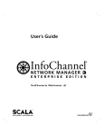
4.1 The Front Panel
State
¡@LED
Description
CH1
ON
OFF
The audio channel 1 is selected
CH2
ON
OFF
The audio channel 2 is selected
CH3
ON
OFF
The audio channel 3 is selected
CH4
ON
OFF
The audio channel 4 is selected
CH5
CH1 CH4 = ON
CH2 CH3 = OFF
The audio channel 5 is selected
CH6
CH2 CH4 = ON
CH1 CH3 = OFF
The audio channel 6 is selected
CH7
CH3 CH4 = ON
CH1 CH2 = OFF
The audio channel 7 is selected
CH8
CH1 CH3 CH4=ON
CH2 = OFF
The audio channel 8 is selected
The audio channel 8 is not selected.
Mode
Always OFF
Always ON
Fast Blink
Slow Blink
Mode 1- Analog Audio Line Out mode (Decode mode-default)
Mode 2- Internet Radio mode (Streaming puller mode)
Mode 3- Analog Audio Line In mode (Encode mode with RCA Line-In
Mode 4- Digital Optical In mode (Encode mode with Optical S/PDIF-I
PL_LNK
ON
OFF
There is the other device on the Powerline Networking
There is no other device on the Powerline Networking
PL_ACT
Flash
OFF
Data transferring on the Powerline Networking
No data transfer
PWR
ON
OFF
Device (Powerline Audio) is powered ON
Device (Powerline Audio) is powered OFF
Channel ¡V This pushbutton is for the audio channel selection. And the LED (CH1-CH4)
will display your channel selection.
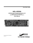
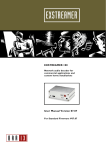
The Rear Panel:
Port
Description
POWER
Power connector with 9Vdc/ 1 Ampere and Powerline
networking also go through this power port
RESET button
The reset button, when pressed shortly, resets the device
(Powerline Audio) without the need to unplug the power
cord.
If you press the button until the red light flashes (over 5
seconds) the device will reset to factory defaults.
OPTICAL IN
S/PDIF Optical digital in
Left IN
RCA jack for left audio line in
Right IN
RCA jack for right audio line in
OPTICAL OUT
S/PDIF Optical digital out
Left OUT
RCA jack for left audio line out
Right OUT
RCA jack for right audio line out
Ethernet
RJ-45 jack for 10/100 M bit Half/Full duplex LAN and it
provides for data transferring to your networking
Ethernet-LNK LED
Ethernet port connects properly when LED is light.
Ethernet-ACT LED
Data is transferring on the Ethernet port when LED is
flashing.
M_SEL
Mode selection:
Mode 1- Analog Audio Line Out mode (Decode mode)
Mode 2 ¡V Internet Radio mode (Streaming puller mode)
Mode 3- Analog Audio Line In mode (Encode mode with
Line-In)
Mode 4- Digital Optical In mode (Encode mode with S/PDIF-
In)
There¡¦s a special feature for this button to toggle the LAN or
Powerline Networking to be used. Press this M-SEL button
over 5 seconds to toggle the networking features between
LAN port and Powerline networking port.
Chapter 5 - Hi-Fi Internet Radio stereo System
5.1 Internet Radio to Hi-Fi stereo system
Formula 1:
Home Hi-Fi stereo system + Powerline Audio = Hi-Fi Internet Radio stereo system
Formula 2:
Active speakers + Powerline Audio = Internet Radio speaker
This application is special for the users to enjoy Internet Radio station on the existing HiFi stereo system.
Actually the device transfers music data directly from Internet to the Hi-Fi stereo
system.
This doesn¡¦t require computer. The music is transmitted via powerline outlet in any
room of your home.
Therefore you don¡¦t need to rewire the cable for Internet. For example: Kitchen,
Bathroom, Living room and Backyard.
And you can have 8 preset Internet Radio channels to select as you wish via channel
pushbutton in front of the
device¡¦s panel without computer help. For sure you can also change the 8 preset
channels for different Internet radio
via web browser.
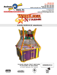
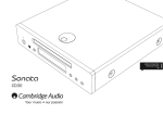
Internet Radio to Hi-Fi stereo System
The following steps are for installing this audio environment without the need to use
computer.
z
Step 1: Make sure your networking is connected with Internet and also support the
powerline bridge function.
z
Step 2: Connect the audio output (Optical or Analogue) of the device into the audio
input (Optical or Analogue)
of the Home Hi-Fi stereo system.
z
Step 3: If DHCP server is supported in your networking, you just plug-in the power
of the device (Powerline Audio).
And listen the IP announcement from your Hi-Fi stereo system. If the IP is belong to
your networking. Do next step.
z
Step 4: Press the M_SEL button (mode selection) to Internet Radio mode in rear
panel of the device.
And check the MOD led in always ON status. That means the device is in the
Internet Radio mode.
It should hear the first Internet Radio within 30 seconds from your Hi-Fi stereo
system.
z
Step 5:Press the Channel button to select the different Internet Radio channel.
Note: These 8 preset Internet Radio channels may be closed sometimes in this
device.
Therefore you can push the channel button to make sure that the Internet Radio
works in different channel.
Of course you also can change these channels to the other Internet Radio station
by the web console of the
device.
5.2 How to set Internet Radio into the device
There are 8 preset Internet Radio stations in the device, the following procedure is for
user to get new
Internet Radio and save them as you like.
Where to find the Internet Radio
Please install WinAmp application software (http://www.winamp.com) in your computer
system, you can find
a lot of Internet Radio stations easily.
After get and install the WinAmp, you can have the screen as follows. First click the
Streaming Media->
Internet Radio to get the Internet Radio station.
Click the right button of mouse on the Internet Radio in the Playlist Editor to get its file
information.
From the information¡¦s box of the WinAmp¡¦s Playlist Editor, you can have the Internet
Radio¡¦s IP and its port number.
Please copy this address and port number into the device.
Set Internet Radio into the device (Powerline Audio)
Please check the chapter for installing the device to your network before you do the
following setting.
Paste the Internet Radio addresses and port number into the device¡¦s web console
(Powerline Audio).
And then click ¡§Apply¡¨ in the web console of the device.
Do the same procedure for all 8 channels as you wish. Then you can use these 8
channels Internet Radio
without computer in any room of your home.
When you start to use the Internet Radio or switch the channel, the channel LEDs will
help you monitor the status
of operation. In the beginning the channel LED will blink in order to synchronize the
channel with the Internet Radio.
When the device¡¦s channel LED stops flashing and remains lit continuously. That
means the music is streaming
from Internet Radio to the device. And then you can enjoy the music from Internet
player.
Note1: There are some Internet Radio stations that do not support MP3 standard.
Therefore the device can¡¦t work with all of Internet Radio stations as listed in the
WinAmp.
Note 2: Because of the definition of the optical interface (s/pdif) for sampling rates 32,
44.1 and 48khz only,
some Internet Radio can play out to RCA line out only.
Chapter 6 - Multi-Room Audio System
6.1 Multi-Room Audio System
DVD/VCD/MP3/CD/AM/FM player + one Powerline Audio = Audio Source1
Computer with Music server + one Powerline Bridge = Audio Source2
Computer + one Powerline Audio = Audio Source3
Hi-Fi stereo system + one Powerline Audio = Audio Player1
Active speakers + one Powerline Audio = Audio Player2
Computer + one Powerline bridge = Audio Player3
This application is special for Whole-house music as an amenity. The users enjoy music
in any room of your
home without rewiring or any new cable. Powerline Audio's whole-house system makes
multi-room music
easier to plan, install and enjoy. The music is transmitted via power outlet and you can
listen music throughout
your home. For example: Kitchen, Bathroom, Living room and Backyard.
To build the multi-room audio system, you need at least two devices (Powerline Audio).
One is for audio source
and the other is for audio player. Of course you can prepare more devices to build the
flexible audio system for
multi-audio player or multi-audio source.
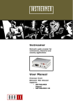
Multi-Room Audio System
For single-audio source case music can be transmitted from one Audio Source to eight
Audio Players at the same time.
For multi-audio source case eight source can operate simultaneously. Therefore all
Audio Players can be
selected and listen any one of Audio Sources as user like via channel-button selection.
There are two parts for installing the multi-room audio system without the need to use
computer.
One is Audio Source installation and the other one is Audio Player Installation.
One Audio Source installation
z
Step 1: Connect the audio output (Optical or Analogue) of the DVD/VCD/MP3/CD
player into the audio input
(Optical or Analogue) of the device.
z
Step 2: Plug-in the power of the device (Powerline Audio).
z
Step 3: Press the M_SEL button (mode selection) to the audio input mode in rear
panel of the device.
And check the MOD led in the blinking status. If LED is fast blinking, the device is
selected in the Analogue
input mode (RAC Line In). If LED is slow blinking, the device is selected in the
Optical input mode (S/PDIF In).
Note: The optical/analogue input mode also plays music from input source on the
Analogue output
(RAC Line Out) and the Optical output (SPDIF Out) at the same time. You can use this
feature to
make sure the input source is right or wrong.
z
Step 4: Press the Channel button to change to the different channel.
Note: Only one audio source can occupy one channel. Don¡¦t use more than one audio
sources set in the same channel. The different audio sources should have their
individual channel.
The maximum audio sources that can be created simultaneously are 8.
One Audio Player installation
z
Step 1: Connect the audio output (Optical or Analogue) of the device into the audio
input (Optical or Analogue)
of the Hi-Fi stereo system (or active speaker).
z
Step 2: Plug-in the power of the device (Powerline Audio).
z
Step 3: Press the M_SEL button (mode selection) to the audio output mode in rear
panel of the device.
And check the MOD led in always-dark status. That means the device is selected in
the audio output mode.
Note: The audio output mode always plays music on the Analogue output (RAC Line
Out) and the Optical output (SPDIF Out) at the same time.
z
Step 4: Press the Channel button to change to the channel as set in the Audio
Source.
If there are several Audio Sources in the environment, you can select them via pressing
Channel button
After you set Audio Source and Audio Player with the same channel, the audio will be
sent from Audio-source to
Audio-player. You can check the whole procedure by monitoring channel LEDs.
In the beginning the channel LED will blink in order to synchronize the audio channel on
the audio networking.
When the audio player stops flashing and remains lit continuously. That means the
music is streaming from audio
source to audio player. And then you can enjoy the music from audio player.
6.2 Music server to Hi-Fi stereo system
Music Server to Hi-Fi stereo System
First you need a powerline bridge device for computer to get in the Powerline audio
system
Second install three software components to build a music server for your computer.
1> Install the WINAMP software (http://www.winamp.com)
2> Install the SHOUTcast DSP Plug-In for the WINAMP software
(http://www.shoutcast.com/download/broadcast.phtml#streams or
http://www.shoutcast.com)
I3>Install the SHOUTcast server (http://www.shoutcast.com/download/serve.phtml or
http://www.shoutcast.com)
Third try to get the IP address of the device as audio source via SonicIP features.
You can get the IP announcement during the device power-up (Powerline Audio as
audio source).
Record and use it in later procedure.
For example: 192.168.16.3.
In order to broadcast audio using WINAMP, you¡¦ll need to have a SHOUTcast server
for WINAMP to connect to.
The purpose of the SHOUTcast server is that it allows people using WINAMP connect to
it and begin downloading
content being streamed live off the Internet, and the content is live, and up to the minute.
This server software allows
many people to connect, assuming you have enough bandwidth, memory, and CPU.
Your broadcasters use
WINAMP and the SHOUTcast Source Plug-in for Winamp to send data to your server
and the server then relays the data back to your listeners. The person running the
SHOUT cast server has the ability to administer the server itself via HTML and a simple
configuration file.
In order to broadcast to a running SHOUTcast server, you will need the SHOUTcast
Source for Winamp x.x DSP Plug-in, a piece of software which adds SHOUTcast
broadcast ability to the Winamp x.x software. The DSP
Plug-in acts as a bridge between your Winamp software and a SHOUTcast DNAS
server (which you or a friend
need to be running to broadcast).
Build a Music Server for your computer
Step 1 ¡V Install the WINAMP, WINAMP Plug-In (SHOUTcast DSP Plug-In) and
SHOUTcast server
Step 2 ¡V Open the SHOUTcast server and check the port base. (Default port number is
8000)
Step 3 ¡V Open the WINAMP ¡§ Option -> Preferences¡¨
Step 4 ¡V Select ¡§Plug-ins -> DSP/Effect¡¨
Step 5 ¡V When the client windows display, click ¡§connect¡¨ button and check the
password with ¡§changeme¡¨,
Port number with 8000 and Address with ¡§localhost¡¨. (If you have any problem on
these parameters, please run
¡§Edit SHOUTcast DNAS configuration¡¨ program of SHOUTcast server to check them.)
Step 6 ¡V After the SHOUTcast server sets successfully, just play the music on
WINAMP and it will
start to send the streaming audio. Click the ¡¨MAIN¡¨ icon to monitor the streaming
status.
Step 7- Find the IP address of this computer and record it for the Powerline audio device
setting.
For this example IP address is 192.168.16.14.
Step 8 ¡V Open the web management of the Powerline audio device. And go to
¡§Configuration ->Streaming¡¨.
Set Mode to Streaming Puller mode and fill in the IP address (for this example:
http://192.168.16.14:8000).
Click Apply after setting.
6.3 Computer as an Audio Player within Multi-room Audio system
Multi-Room Audio System
First you need a powerline bridge device for computer to get in the audio system
Second try to get the IP address of the device as audio source via SonicIP features.
You can get the IP announcement during the device power-up (Powerline Audio as
audio source).
Record and use it in later procedure. For example: 192.168.16.3.
Third use WINAMP software or Windows Media Player and type the IP address you get
from previous step.
WINAMP as an audio player
Step 1- Go to the Playlist Editor of the WINAMP.
Step 2- Click ¡§File¡¨ icon and select ¡§Add URL¡¨
Step 3- Type in the IP addresses and channel number of the device you get form
SonicIP
(Powerline Audio as audio source). After this setting, you can listen the music from your
audio source.
Window Media Player as an audio player
Step 1- Go to the Window Media Player
Step 2- Type ¡§Ctrl+u¡¨ to get the add URL screen as below.
And then type in the IP addresses and channel number of the device you get form
SonicIP
(Powerline Audio as audio source). After this setting, you can listen the music from your
audio source.
Chapter 7 - Installing the device to your network
This device provides two ways to work with your network. One goes through Powerline
Networking
as factory default and the other one goes through Ethernet Networking (RJ-45). And this
device can only
provide one way at one time. Therefore the M_SEL button (Pressing over 5 seconds)
provides to
toggle between Powerline Networking and Ethernet Networking.
7.1 Powerline Networking Type
STEP 1
Build a Powerline bridge on your networking.
STEP 2
Connect the audio output (Optical or Analogue) of the device into the audio input
(Optical or Analogue)
of the Hi-Fi stereo system (or active speaker).
STEP 3
Plug the power supply into the device (Powerline Audio).
STEP 4
The device will now search for a DHCP server to get an IP address and announce this
address over audio
output (RCA line out).
Example: 192.168.16.3 (Voice: one nine two dot¡K)
Make sure you write this IP address down. If no DHCP server is found then the device
will assign a free IP address.
7.2 Ethernet Networking Type
STEP 1
Plug the straight-through network cable into the network port of the device (Powerline
Audio) and the other
end into your hub or switch. Or you can also use a crossover network cable for a direct
connection to your PC.
STEP 2
Connect the audio output (Optical or Analogue) of the device into the audio input
(Optical or Analogue) of the
Hi-Fi stereo system (or active speaker).
STEP 3
Plug the power supply into the device (Powerline Audio).
STEP 4
The device will now search for a DHCP server to get an IP address and announce this
address over audio
output (RCA line out).
Example: 192.168.16.3 (Voice: one nine two dot¡K)
Make sure you write this IP address down. If no DHCP server is found then the device
will assign a free IP address.
Chapter 8 - Configuring with Web Browser
Once the device (Powerline Audio) is connected to your network, it will automatically
receive an IP address
from your DHCP server (Internet gateways run usually a DHCP server). If no DHCP
server can be reached,
the device (Powerline Audio) will assign one IP address automatically.
The device will announce the IP address using Sonic IP technology to RCA line out.
Open the web browser and enter the local port IP address of the device, which get from
Sonic IP http://xxx.xxx.xxx.xxx.
This device has a local web server built in. You can control it from anywhere on your
network via a standard web browser
from your computer.
z
Status - Home page
The Home page shows the operation mode, channel number status and audio control.
The audio control is only valid in audio RCA line out mode.
The following audio control is only valid in audio RCA line out mode.
MUTE
This action mutes the audio output. Click again to activate audio or click on the volume
slider.
PLAY
This action plays the music.
PAUSE
This action stops playing the media file but keeps the progress at the spot it was at when
the player was
paused so you can continue listening from the same position.
STOP
This action stops playing the media file.
SET
This action brings you to the audio adjustment interface.
(+)
This action increases the volume by increment.
VOLUME SLIDER
This action lets you adjust the volume level. Click closer to the + (plus) sign for higher
volume or closer to the ¡V
(dash) sign for lower volume.
(-)
This action decreases the volume by increment.
Mode status
Mode 1- Analog Audio Line Out mode (Decode mode)
Mode 2 ¡V Internet Radio mode (Streaming puller mode)
Mode 3- Analog Audio Line In mode (Encode mode with RCA Line-In)
Mode 4- Digital Optical In mode (Encode mode with Optical S/PDIF-In)
Channel status
There are 8 channels provided by this device.
z
Quick Setting for audio adjustment
Click Set icon in Home page and get into this quick audio adjustment page. It provides
Balance, Bass,
Treble and loudness control. This audio adjustment is only valid in audio RCA line out
mode
(Decode mode with RCA line out).
BALANCE
This action adjusts the Left and Right audio balance.
Click into the Balance bar to set the balance to a specific position or click <L> or <R> to
move the position to
the appropriate side in steps.
BASS
This action adjusts the bass level. Click into the Bass bar to set the bass to a specific
level or click <+> or <-> to
increment/decrement the bass level in steps.
TREBLE
This action adjusts the treble level. Click into the Treble bar to set the treble to a specific
level or click <+> or <-> to
increment/decrement the treble level in step
LOUDNESS ON
This action turns on the loudness level.
LOUDNESS OFF
This action terminates the loudness level.
SET AS DEFAULT
This action saves the current settings as default. Every time you restart the device it will
use these settings.
The device will restart
PLAY
This action brings you back to the Home Page.
z
Status - Device Configuration page
Click Config icon in Home page and get into this Device Configuration page. It provides
a lot of information
that include MAC address, Firmware version, Audio control, factory default setting,
reboot and update function.
A- INFORMATION FRAME
This frame shows the device¡¦s MAC address, Firmware version, Web application,
Boot loader version and
Setup version.
B- MENU FRAME
This frame shows the available menu icons.
A click on SETTINGS brings you to the settings page.
A click on DEFAULTS brings you to the factory default settings.
A click on REBOOT brings you to the reboot.
A click on UPDATE brings you to the update page.
A click on HOME brings you back to home page.
C- HELP FRAME
This frame shows the help for all settings and menus.
D- SETTING TABS
This bar shows the available tabs within the settings menu.
z
Configuration ¡V Networking setting
Click Setting icon in Device configuration page. It provides IP address setting of the
device.
Here you can configure the device's Static IP address. With this you can set a
permanent IP address so that
the device does not have to get a new one upon power-up.
IP Address
Enter the 4 values of the desired device IP address e.g.: "0.0.0.0" for automatic
discovery ( DHCP /Bootp )
"192.168.16.12" for an internal LAN
Default: "0.0.0.0"
Netmask
Enter the 4 values of the desired Static IP e.g.: "0.0.0.0" for a default Netmask
depending on the used IP
Address."255.255.255.0" for a C class network
Default: "255.255.255.0"
Gateway IP Address
Enter the 4 values of the desired Gateway IP address e.g.:"0.0.0.0" for no Gateway
"192.168.0.1" for a Gateway in a LAN
Note: The Gateway has to be set only when connecting to other devices over the WAN
(through a router).
Default: "0.0.0.0"
Ethernet Interface
Choose between LAN (RJ-45) or Powerline. This device offer the local networking via
Ethernet wiring or Powerline Networking.
Default: "Powerline"
Use SonicIP®
If set to "yes", the device will announce its IP address over the audio output.
Default: "yes"
To store these settings click on "Apply". The device will restart with the new setting.
z
Configuration ¡V Streaming setting
Click Streaming icon in Device configuration page. It provides the streaming mode
selection, channel selection of the device.
Here you can adjust the way the device (Powerline Audio) will get its stream.
Mode
Choose between decode (output mode), encode (input mode) and streaming puller
mode. Default setting is "Decode".
z
Streaming Puller Mode
This mode enables the device to stream MP3s from most brands of MP3 jukeboxes on
the market that is Internet Radio station.
In Streaming Puller mode the device works as a Streaming Puller. It connects to the
server
configured
in
the
server
path
and plays that stream.
z
Decode Mode
This mode enable the device works as a simple passive streaming receiver and play the
music
out
on
the
RAC
line out and S/PDIF Optical out.
z
Encode Mode
This mode enable the device works as a simple passive streaming transmitter and get
the
music
from
the
RAC
line
in
or S/PDIF Optical in (Depending the input source setting of audio)
Channel
Select and display channel 1..8. Default setting is "1".
Internet Radio Channel 1 ¡V 8
This setting is valid only for the streaming puller mode. Enter the URL of the Internet
radio for the corresponding channel.
Used in Streaming Puller mode. Keep the field empty for usage of the built in Internet
radio list.
Default setting is "".
General settings
Start Threshold
The Start Threshold is the amount of bytes the device will buffer the stream before
starting the playback.
Valid is a value from 0 to 65535.
Buffer Under run Timeout
The Buffer Under run Timeout defines the amount of time in seconds since the
streaming buffer is empty until the
Buffer Under run Mode action will be executed.
Default setting is "2".
Connection Timeout
The Connection Timeout defines how many milliseconds to wait for a TCP streaming
connection.
Default setting is "1000".
z
Configuration ¡V Audio setting
Click Audio icon in Device configuration page. It provides IP address setting of the
device.
You only need to adjust this section if you would like your device to start up with custom
sound adjustments.
For example you would like your device to always start with maximum bass, than you
could adjust that here
to become default. These adjustments will be stored even if the unit looses power.
Output settings
Volume - Choose between "0%" and "100%" in 5% steps. Default setting is "50%".
Mute Volume - Choose "On" to mute the sound output at startup else choose "Off".
Default setting is "Off".
Balance - Choose between "Left max." and "Right max." (L10..R10). Default setting is
"Middle".
Bass - Choose between "-10" and "10". Default setting is "0".
Treble - Choose between "-10" and "10". Default setting is "0".
Loudness Level - Choose between "0" and "20". Default setting is "20".
Loudness - Choose between "On" and "Off". Default setting is "Off".
Output Mode ¡V Choose between ¡§Stereo¡¨ and ¡§Mono¡¨. If Mono is selected the
audio output is always mono.
Default setting is "Stereo".
Configuration Auto Store - Stores the configuration automatically 30 sec after the last
change in the control interface.
The stored parameters are volume, mute, volume lock, balance, bass, treble, loudness
on/off, shuffle and repeat.
Default setting is "0".
Input settings
Input source - Choose the desired input source. Default setting is "MP3".
Channel Mode - Select between "stereo" and "mono" input mode. Default setting is
"stereo".
Encoding Quality - Choose between "0 lowest" and "7 highest" in steps of 1.
The Encoder Quality table below shows the average bit rate in kbps for the quality
settings and sampling frequencies in kHz.
Default setting is "0 lowest".
0
1
2
3
4
5
6
7
Quality
44.1
65 68 73 80 90 105 125 140
22.05
35 38 40 45 50
60
75
90
Sampling Frequency - Choose between 6 different settings.
From "MPEG1 / 48 kHz" down to "MPEG2 / 16 kHz".
In case of S/PDIF audio input, MPEG1 is used and the sampling frequency is auto
detected.
Default setting is "MPEG2 / 22.5 kHz".
Advanced Encoder settings
A/D amplifier gain - Choose the desired gain ("-3" - "19.5" dB) for the A/D amplifier
(only for the line input).
Default setting is "-3" dB.
MP3 Frame CRC - If the device is set to "enable", the encoder will include the CRC-16
to each MP3 frame.
Default setting is "enable".
MP3 Bit reservoir Mode - The Bit reservoir is used to compensate the differences
between the predefined frame sizes.
If set to "used", the encoder will use the bit reservoir.
Default setting is "used".
MP3 Channel Mode Extension - "Enable" or "disable" the MS-Stereo encoding (for
stereo only).
Default setting is "enable".
MP3 Copyright Protection - "Enable" or "disable" the copyright protection bit in the
MP3 bit stream.
Default setting is "enable".
MP3 Stream Type - Select between a "copy" and an "original" bits ream in order to set
the appropriate bit in
the MP3 bit stream. Default setting is "copy".
MP3 Emphasis - Select emphasis among "none", "50/15 us" or "CCITT J.17". Default
setting is "none".
z
Configuration ¡V Back to factory default
Click
defaults.
in Device configuration page. It provides how to back to factory
Click on "Factory defaults" to revert all settings except "Network configuration" to
factory defaults.
While restarting the device the following screen appears showing a number counting
down:
Upon start up the following screen appears the successful message and the device
reverts to factory defaults.
Set default settings by hardware-reset button
The device reverts all settings (including the "Network configuration") to factory defaults.
The Reset button has to be pressed for about 5 seconds while the device is powered.
If the Reset button is pressed for less than 5 seconds, the device implements reboot
only with keeping the current parameters.
z
Click
Configuration ¡V Back to factory default
in Device configuration page. The device will reboot itself.
Click Reboot the device to restart the device. While restarting the device the following
screen appears
showing a number counting down.
Upon start up the following screen appears stating the successful restart:
z
Configuration ¡V Update new firmware
in Device configuration page. It provides a procedure to upgrade the
Click
new firmware for this device.
STEP 1
Click on "Please click here to continue" to launch the update process. The device will
restart in a special
mode called Bootloader and the following screen appears showing a number counting
down:
Upon start up the following screen appears ready for the update process.
STEP 2
To upload an update click on "Browse..." to locate the file you want to update. The file is
named xxx.bin
Once selected, click on "Upload". This process can take a few minutes.
After a successful upload the following window appears:
Click on the update link before updating the next component. Unplug power supply to
reboot the device or type
in reboot in the resource field and click on ¡§Upload¡¨.
The following screen appears:
STEP 3
Close the browser window. After the device has rebooted, please open a new browser
window to continue.
Chapter 9 - Home Audio Scenarios
The following scenarios are some Home Audio applications. And you can build them
easily according to the
previous chapters description.
Multi-Room Audio System
Internet Radio to Hi-Fi stereo System
Music Server to Hi-Fi stereo System
DVD/VCD/MP3/AM/FM to Hi-Fi stereo System via Powerline
Computer to Hi-Fi stereo System via Powerline
Internet Radio to Hi-Fi stereo System via Ethernet
Network to Hi-Fi stereo System via Powerline
Music Server to Multi-Audio
Internet Radio to Multi-Audio
DVD/VCD/MP3/CD/AM/FM to Multi-Audio via Powerline
Multi-Audio Source to Multi-Audio Player
Multi-Audio Source to Multi-Audio Player
Home Audio System
Multi-Room Audio System
Workroom to Multi-audio Player
Chapter 10 - FAQ and Troubleshooting
Q: I don¡¦t see any status lights on at all.
A: Make sure the power cable is correctly plugged into the unit and make sure the power
supply is plugged into
the power outlet on the wall.
Q: How do I ping the device to see if it¡¦s on my network?
A: You can ping any device on your network by opening a DOS command box.
Type ping and the IP address of the unit to see if you can get a response.
Example: ping 192.168.16.10
The proper response would be to see the message ¡§reply from 192.168.16.10¡¨.
If you see the message ¡§request timed out¡¨, it means that this device (Powerline
Audio) is not on your network or
that you have entered the wrong numbers for the IP address.
Q: When I type in the IP address in the browser I get a ¡§This Page Cannot Be
Displayed¡¨ Message.
A: This means that you can¡¦t connect to the device. There could be a couple of different
reasons. Make sure you
are typing in the IP address correctly. Check the cables to make sure the device is
properly connected to the network.
Q: Will this device work on my operating system?
A: The device works on virtually any operating system. To control the device a standard
web browser is all you need.
Chapter 11 - Technical specifications
z
Audio Format:
MP3- MPEG 1/2 Layer 2 and Layer 3, at up to 192 Kbps, including variable bit rate
(VBR),
z
Audio Interfaces:
Stereo RCA Line out (4.2Vpp max)
Stereo RCA Line in (2Vpp max)
SNR>90dB,
Frequency Response: -0.05dB (20Hz), 1.45dB (20kHz)
RCA Line in/out (Analog)
S/PDIF in/out (Optical)
EQ (Encoding Quality), volume control, mute, balance, loudness, bass and treble
adjustable by browser
z
Network Interface:
Powerline Networking or RJ45 10/100 M-bit Ethernet, TCP/IP,UDP , ICMP, DHCP,
SonicIP®, integrated
web server for configuration
z
Miscellaneous:
Eight LED status indicators
Reset/Factory default button
Channel selection button
Mode selection button
z
Power requirements:
9 VDC 1A power supply included
Consumption: max. 4W
z
Certifications:
FCC, CE
z
User Interface:
Browser based,
Push button (Reset, Mode and Channel selection)
Chapter 12 - Glossary
z
DHCP
Short for Dynamic Host Configuration Protocol, DHCP is a protocol used to assign an IP
address to a
device connected to a Network.
z
IP
The 32-bit address assigned to hosts that want to participate in a TCP/IP Internet. Short
for Internet Protocol,
the IP is an address of a computer or other network device on a network using IP or
TCP/IP. Every device on
an IP-based network requires an IP address to identify its location or address on the
network.
Example: 192.168.16.10
z
MAC address
Media Access Control Layer - A sub-layer of the Data Link Layer (Layer 2) of the ISO
OSI Model responsible
for media control. Abbreviation for Medium Access Control, a MAC is a unique address
number formatted in
hexadecimal format and given to each computer and/or network device on a computer
network. Because a MAC
address is a unique address a computer network will not have the same MAC address
assigned to more than
one computer or network device.
Example: A1:B2:C3:D4:E5:F6
z
Netmask
A number used to identify a sub network so that an IP address can be shared on a LAN
(Local Area Network).
A mask is used to determine what subnet an IP address belongs to. An IP address has
two components, the
network address and the host address. For example, consider the IP address
150.215.17.009. Assuming this
is part of a Class B network, the first two numbers (150.215) represent the Class B
network address, and the
second two numbers (.017.009) identify a particular host on this network. The Netmask
would then be 255.255.0.0
z
Ping
Ping is a basic Internet program that lets you verify that a particular IP address exists
and can accept requests.
Example: ping 192.168.16.10
z
Sonic IP
Sonic IP® technology is designed to vocally announce the device¡¦s current IP address.
This makes it easier and faster to obtain the necessary network information.
To make use of Sonic IP plug to RCA audio out, connect the network and plug in the
power supply.
It will announce the address over the speaker after power up. Sonic IP are trademarks
or registered trademarks of BARIX.
z
HTML
Hypertext Markup Language - The page-coding language for the World Wide Web.
z
HTML browser
A browser used to traverse the Internet, such as Netscape or Microsoft Internet
Explorer.
z
http
Hypertext Transfer Protocol - The protocol used to carry world-wide-web (www) traffic
between a www browser
computer and the www server being accessed.
z
ICMP
Internet Control Message Protocol - The protocol used to handle errors and control
messages at the IP layer.
ICMP is actually part of the IP protocol.
z
Internet address
An IP address is assigned in blocks of numbers to user organizations accessing the
Internet.
These addresses are established by the United States Department of Defense's
Network Information Center.
Duplicate addresses can cause major problems on the network, but the NIC trusts
organizations to use individual
addresses responsibly. Each address is a 32-bit address in the form of x.x.x.x where x is
an eight- bit number from
0 to 255. There are three classes: A, B and C, depending on how many computers on
the site are likely to be connected.
z
Internet Protocol (IP)
The network layer protocol for the Internet protocol suite
z
ISP
Internet service provider - A company allows home and corporate users to connect to
the Internet.
z
Static IP Addresses
A Static IP is a fixed IP address that you assign manually to a device on the network. It
remains valid until you
disable it. A static IP address is an IP address permanently assigned to computer in a
TCP/IP network.
Static IP addresses are usually assigned to networked devices that are consistently
accessed by multiple users,
such as Server PCs, or printers. If you are using your Router to share your cable or DSL
Internet connection,
contact your ISP to see if they have assigned your home a static IP address. You will
need that address during
your Router's configuration.
z
Subnet
For routing purposes, IP networks can be divided into logical subnets by using a subnet
mask.
Values below those of the mask are valid addresses on the subnet.
z
TCP
Transmission Control Protocol - The major transport protocol in the Internet suite of
protocols provides reliable,
connection-oriented full-duplex streams.
z
TFTP
Trivial File Transfer Protocol - A simple file transfer protocol (a simplified version of FTP)
that is often used to
boot diskless workstations and other network devices such as routers over a network
(typically a LAN).
z
Telnet
The virtual terminal protocol in the Internet suite of protocols - Allows users of one host
to log into a remote
host and act as normal terminal users of that host.
z
Transparent bridging
So named because the intelligence necessary to make relaying decisions exists in the
bridge itself and is thus
transparent to the communicating workstations. It involves frame forwarding, learning
workstation addresses and
ensuring no topology loops exist (in conjunction with the Spanning-Tree algorithm).
z
UDP
User Datagram Protocol - A connectionless transport protocol that runs on top of
TCP/IP's IP. UDP, like TCP,
uses IP for delivery; however, unlike TCP, UDP provides for exchange of datagrams
without acknowledgments
or guaranteed delivery. Best suited for small, independent requests, such as requesting
a MIB value from an
SNMP agent, in which first setting up a connection would take more time than sending
the data.
Name
POWER
RESET
S/PDIF IN optic.
LINE IN left
LINE IN right
S/PDIF OUT optic.
LINE OUT left
LINE OUT right
ETHERNET
M_SET
No.
1
2
3
4
5
6
7
8
9
10
Description
Power Jack, integrated with Powerline networking
Optical S/PDIF input, 32 kHz, 44.1 kHz, 48 kHz
Line input left/right RCA, 2Vpp max. level (0dBFs)
Optical S/PDIF output, 32 kHz, 44.1 kHz, 48kHz
Line output left/right RCA, 4.2Vpp max. level (0 dbFs), SNR>85dbFs
(Exstreamer Digital: SNR>90dbFs),
Frequency Response: -0.05dB (20Hz), 1.45dB (20kHz), THDN + N: 0.015% (0dBFs)
Appendix A -
Cabling / Connection
Network cables connect PCs in an Ethernet network Category 5, called "Cat5" for
short is commonly used type
of network cable today.
Cat 5 cables are tipped with RJ-45 connectors, which fit into RJ-45 port.
Straight-through vs. Crossover Cables:
Straight-through
Crossover
Wire
Becomes
Wire
Becomes
1
1
1
3
2
2
2
6
3
3
3
1
6
6
6
2
Appendix B -
Name
POWER
RESET
S/PDIF IN optic.
LINE IN left
LINE In right
S/PDIF OUT optic.
LINE OUT left
LINE OUT right
Connectors of Rear panel
No. Description
1
Power Jack, integrated with Powerline networking
2
The reset button, when pressed shortly, resets the device
(Powerline Audio) without the need to unplug the power cord.
3
4
5
6
7
8
If you press the button until the red light flashes (over 5 seconds)
the device will reset to factory defaults.
Optical S/PDIF input, 32 kHz, 44.1 kHz, 48 kHz
Line input left/right RCA, 2Vpp max. level (0dBFs)
Optical S/PDIF output, 32 kHz, 44.1 kHz, 48kHz
Line output left/right RCA, 4.2Vpp max. level (0 dbFs),
SNR>85dbFs (Digital: SNR>90dbFs),
Frequency Response: -0.05dB (20Hz), 1.45dB (20kHz), THDN +
N: 0.015% (0dBFs)
ETHERNET
9
RJ-45 jack for 10/100 M bit Half/Full duplex LAN and it provides
for data transferring to your networking
Ethernet port connects properly when LNK LED is light.
Data is transferring on the Ethernet port when ACTLED is
flashing.
M_SEL
10
Mode selection:
Mode 1- Analog Audio Line Out mode (Decode mode)
Mode 2 ¡V Internet Radio mode (Streaming puller mode)
Mode 3- Analog Audio Line In mode (Encode mode with Line-In)
Mode 4- Digital Optical In mode (Encode mode with S/PDIF-In)
There¡¦s a special feature for this button to toggle the LAN or
Powerline Networking to be used. Press this M-SEL button over 5
seconds to toggle the networking features between LAN port and
Powerline networking port.
Declaration of CE
This declaration of conformity is according to article 7(3) and article 10(2)
of the Council of European Communities of 3 May 1989.
The protection requirements according the Council Directive article 4
and Annex III are kept.
MODEL / TYPE: Powerline Audio
This declaration is given from the manufacturer
submitted by
TRAINING RESEARCH CO., LTD.
5F,. NO. 571, SEC. 7, CHUNG HSIAO E. RD.,
TAIPEI, TAIWAN, R. O. C.
To the judgement of the products with regard to electromagnetic compatibility
according following regulations:
EN 50081 - 1 ( EN 55022, EN 61000-3-2, EN 61000-3-3 )
EN 55024 ( EN 61000-4-2, EN 61000-4-3, EN 61000-4-4,
EN 61000-4-5, EN 61000-4-6, EN 61000-4-11)
FCC Part 15
The device generates and uses radio frequency energy. If it is not installed and used
properly in strict
accordance with the user's manual, it may cause interference with radio and
television reception. The
device been tested and found to comply with the limits for Class B computing devices
in accordance
with the specifications in Subpart B, Part 15 of the FCC regulations. These
specifications are designed
to provide reasonable protection against such interference in a residential installation.
However, there is
no guarantee that interference will not occur in a particular installation. FCC
regulations require that shielded
interface cables be used with your device.
If interference does occur, we suggest the following measures be taken to rectify the
problem:
1) Move the receiving antenna.
2) Move the device away from the radio or TV.
3) Plug the device into a different electrical outlet.
4) Discuss the problem with a qualified radio / TV technician.
Caution:
Changes or modifications not expressly approved by the party responsible for
compliance to the FCC Rules
could void the user's authority to operate this equipment.
Cable connections:
All equipment connected to this device must use shielded cable as the
interconnection means.
Notes:
Operation is subject to the following two conditions:
1) This device may not cause harmful interference, and
2) This device must accept any interference received including interference that may
cause undesired operation.