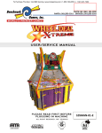
1
105MAN-01-E
0
TABLE OF CONTENTS
> MANUAL REVISION HISTORY..................................................................................................................... 2
1- BASIC COMPONENTS ................................................................................................................................ 3
2- GAME PLAY SEQUENCE/BEHAVIOR .......................................................................................................... 5
3- GAME SETUP ............................................................................................................................................. 7
Recommended Payout Settings ............................................................................................................ 9
4- TECHNICAL OPERATION .......................................................................................................................... 10
Inter-Board Communication ............................................................................................................... 10
Main Electronic Components ............................................................................................................. 11
5- PROGRAMMING OPTIONS ...................................................................................................................... 18
6- ALTERNATIVE CONFIGURATIONS ............................................................................................................ 26
7- ERROR CODES AND TROUBLESHOOTING GUIDE .................................................................................... 31
1
MANUAL REVISION HISTORY
-06-29-10: REV-E Created:
-WDX Game ROM version 1.41 released, modifies pages 2, 6, 13, 21, 31. Other pages not shifted.
-05-03-10: REV-D Created:
--WDX Game ROM version 1.4 released, added description on page 13.
- Added Supplemental descriptions/instructions for Card-Swipe and e-ticketing machine
configurations.
-12-01-09: REV-C Created:
-Moved revision history to second page.
-WDX Game ROM version 1.3 released, added description on page 13.
-Corrected page 12, stating there’s 2 fuses instead of 1.
-Corrected pages 15, 16. Added Opto and Hall-effect part #s
-Corrected page 17, Ticket Dispenser part#.
-Changed section 5 (settings) to reflect new plays/credit feature and payout-ratio taken out.
-Corrected Troubleshooting guide (page 27), replacing 5/8” with 3/8” for pin protrusion.
-10-05-09 REV-B Created
-Updated ‘Programming-Options’ figure and descriptions for
“Prize Table” and “Magnet size” options, and “Current Credits” log.
-Added explanation on why/how ticket dispensers use 485 network.
-Game-ROM version is 1.2 at this point.
-09-28-09 Added Cover Page, updated pictures to reflect no-number targets.
-09-22-09: Added information regarding ticket prize-tables and how to choose them on Programming Mode
-09-14-09: REV-A Created
2
1- BASIC COMPONENTS
PLAYER 4
PLAYER 2
PLAYER 3
Playfield Wheel
Light Spokes
PLAYER 1
ISO VIEW
TOP VIEW
WDX Light Marquee Widget
5-Digit Display
Speaker
Upper Assembly,
Circuit Boards
Coin-Mech
Center Spindle Piece
Ticket
Dispenser
Player Button
Control Panel,
Circuit Boards
(Player 1 Side)
08-26-09 Rev-A
FRONT VIEW
FRONT VIEW (Open Assembly)
Figure 1. Overview of main components
The four player sides are numbered 1,2,3,4 in a clockwise fashion, beginning with the side where the control
boards are located. Each player has a Button, Display, Speaker, Lights, Puck-Ramp, and Playfield sensor pair.
3
Figure 2, Game Sensors (Top View, wheel removed):
Opto-Sensor: Detects Wheel Playfield-Start.
Hall-Effect Magnet Sensor: Detects Puck a the end of its travel.
Stepper Motor
Pucks ready
to be raised
Figure3, Puck Ramp Mechanism, Underneath Playfield Base.
There are three actions taken by this ramp:
Puck-load (seen in picture), Puck-Arm (ready to play), and Puck-Kick (play)
4
2- GAME PLAY SEQUENCE/BEHAVIOR
I-Power-up initialization Sequence (about 20 seconds):
This is useful to quickly confirm that the machine features are operational.
-Wheel will start rotating.
-Playfield White-Lights will light up, one player at a time (1,2,3,4, clockwise),
also, Displays will show an attraction sequence.
- Pucks will then be kicked out one at a time (1,2,3,4 clockwise) and
a sound will accompany each; this lets you know if the speakers/sound channels correspond to the
appropriate player sides.
-When each Puck is detected by the corresponding Hall-Effect Sensor, you will hear
a “chirp” sound, and the corresponding player lights will flash for a moment. This
lets you know the Puck-detection system is in working order (for each player).
-Finally, the center-piece spindle will start spinning (counter-clockwise) pretty
quickly for a few seconds, and then come back down to a slow speed.
5
II- Attraction Mode:
-Various light patterns are shown while the background sound plays on.
All these ‘ease’ down eventually to avoid being repetitive.
III- Player adds coins (Coin-Mech or Card-swipe system):
- “Coin-in” sound is heard on player-side.
- Common Jackpot value increments, shown on all four Displays.
IV- Credits are obtained:
-“Credits” digit on Display is incremented
(up to “9” shown; higher values are honored though).
- Play-mode start sound (“sweep” sound) is heard on corresponding player-side.
- Wheel Playfield Lights-up.
V- Player Hits Button:
- Puck is kicked into Wheel-Playfield by center Puck-ramp.
- Credit will be discounted.
- Play action sound is played on player side as puck makes its way down the wheel.
- Neon Lights flash momentarily.
- Puck travels down spoke-arm until it ends up over the wheel playfield targets.
VI- Puck is detected by Hall-Effect Sensor:
-Ticket Prize is awarded according to the following criteria:
>Puck centered (aligned) over central Jackpot-Target:
Jackpot-Fanfare is entered.
>Puck centered (aligned) over any other target:
“Dead Center Bonus” will be awarded (x5 times the target value)
Prize Tolerance Window
>Puck not aligned:
Prize will be awarded according to prize table found on player window.
The “Mystery Bonus” is a random value, up to 2.5 times the value of the center prize .
Note: See Programming Mode -> prize-table section on this manual to see how to set
the ticket-values awarded.
-Appropriate prize-sound will be called.
-Prize value awarded will flash on Display momentarily.
-Credit and Jackpot values will be updated on al four Displays if necessary.
-When done, game will come back to Play-mode or Attraction, depending on
whether there are credits left or not.
6
3- GAME SETUP
Unloading/Assembly
The game is pre-assembled in the factory, all you have to do is unpack it and check/locate the following:
-The Game-door keys are tie-wrapped to Player1 Button.
-There’s a “Crystal Ball” stored inside Player 1’s Ticket-drawer. This should go
inside the playfield area, laying over the center piece spindle. No fastener or glue
is required.
-There should be 5 Play-Pucks per player, already loaded on their corresponding
ramps, under the playfield board.
Inspect this by peeking under one of the lower doors.
-Remove any shipping foam that might still be holding any parts, specially the
playfield pointers (spokes).
-Check wheel moves freely, listen for any friction. You should mainly feel the drag of the motor.
-The power cord is also stored inside Player 1’s Ticket-drawer. Connect this to the
power supply, inside Player 1’s lower door. Route the cord, passing it through
the hole on the left bottom corner of the cabinet (Player 1’s side).
7
Power up
Plug-in the machine and turn it ON from the Switch located on the Power supplies.
POWER
SUPPLY 1
POWER
SUPPLY 2
Covered
Covered
Covered,
No Switch
POWER
SUPPLY 3
AC INPUT,
IEC-C13 PLUG
2 Fuses Within
(10A, 250V each)
Covered,
No Switch
MAIN POWER
ON-OFF
SWITCH
-Observe the Initialization sequence, as described in section 2-I.
Any major anomaly, if present, should be seen at this point.
Note: There are two AC fuses on the Power supply group (10Amp, 250V each). It is found inside of the ICE-C13
receptacle on the power supply. The other power supplies are in series with this one.
First-Time Setup
-Run through the ‘Programming Mode’ options and define your desired settings, like sound volume etc
(See Section 5).
- Run the ‘Calibration Routine’ on ‘Programming Mode’ to ensure game accuracy is in order (See section 5-13).
Note that this calibration is done in the factory, but it’s best to re do it in the field, in case vibration during
shipping or other factors moved things around.
-During and after calibration, try the game with the acrylic windows removed, so you can manually place the
Play-Puck in the Jackpot position, etc.
8
Recommended Payout Settings
-Section 5 of this manual describes the different Settings that can be used to configure the machine. From
those settings, the following are the ones that will most likely affect the payout-percentage and the income of
the machine:
-Coins-per-credit and Plays-per-credit.
Note that the actual coin value is determined by your coin-mech/swipe-card configuration,
i.e. the ‘coin’ could be $0.25 or $1.00, without the game having to be aware of this.
-Prize Table (see section 5, page 21, for the table layouts)
-Jackpot minimum, maximum and increment.
-Wheel speed
(it is recommended to keep this at its default value of 10)
-Puck prize window tolerance (it is recommended to keep this at its default value of 20)
There is an Excel payout estimator for this game on the ‘Downloads’ section of our website, the file is
WDX PAYOUT CALC.xls
This allows you to plug in different configuration values and get an idea of the expected payout %.
Note: Always remember that actual income is more important than the payout-percentage alone, as a smaller
payout does not necessarily mean that you’re getting more money from the machine.
The following examples are some recommended standard settings that can be tried and later adjusted
according to your demographics:
“Dime” Play (this one may give a payout above 30%, but it might still be worth trying).
Coins-per-Credit: 1 ($0.25 coin) Plays-per-Credit: 2
Coins-per-Credit: 1 ($1.00 coin) Plays-per-Credit: 7
Prize Table:
“A”
Jackpot Minimum: 200
Maximum: 1000
Increment: 1
25 Cent Play
Coins-per-Credit:
Coins-per-Credit:
Prize Table:
Jackpot Minimum:
1 ($0.25 coin)
Plays-per-Credit: 1
1 ($1.00 coin)
Plays-per-Credit: 4
“A”
200
Maximum: 3000
Increment: 4
50 Cent Play (Factory Default)
Coins-per-Credit: 2 ($0.25 coin)
Plays-per-Credit: 1
Coins-per-Credit: 1 ($1.00 coin)
Plays-per-Credit: 2
Prize Table:
“C”
Jackpot Minimum: 300
Maximum: 5000
Increment: 5
1 Buck Play
Coins-per-Credit:
Coins-per-Credit:
Prize Table:
Jackpot Minimum:
4 ($0.25 coin)
Plays-per-Credit: 1
1 ($1.00 coin)
Plays-per-Credit: 1
“E”
300
Maximum: 9999
Increment: 5
9
4- TECHNICAL OPERATION
Inter-Board Communication
The Circuit Boards communicate with each other using a 485 differential wire-pair network, using the SNAP
software protocol layer.
- On this machine, this wire pair has colors Blue and Gray.
- The Main CPU Board acts as the master, initiating commands and receiving responses.
- Like-boards differentiate from each other by means of an ID-Switch setting. See the following pages to find
each board’s ID-Switch location and setting.
- Note that the following boards are NOT connected to the 485 network:
> The Power distribution boards.
> The LCD Display.
> The Opto and Magnet Sensors. Each of these has a direct line to the appropriate
target board’s logic Inputs .
-Note that the 485 network wire-pair chain jumps from board to board:
> In some places the chaining is done by double-crimps at the connector
(these are usually 2-pin connectors)
>In other places, PCB traces on the board itself carry the chain from a pair of connector pins
to the next (usually a four-pin connector); thus, disconnecting such a board’s 485 might actually
disconnect the rest of the 485 chain. Keep this in mind when troubleshooting or replacing parts.
10
Main Electronic Components
Control Panel Assembly
Upper Assembly (Seen from underneath)
IO-Expander 1
LCD Display
IO-Expander 2
Quad Stepper 2
MAIN CPU Board
Sound Board 1, Players 1,2
Quad Stepper 1
Power Distribution 1
Sound Board 2, Players 3,4
Power Distribution 2
Power Distribution 3
Figure 5. PCB Boards, Control Panel
Figure 6. PCB Boards, Upper Assembly
Figure 7. Sensing Components
11
Power Distribution Boards
OUTPUTS
Switch 3
Circuit overload LEDs
Distributes DC power from the power-supply to the different devices,
through a Poly-Switch (thermal, resettable fuse) for each voltage circuit.
The game uses a power distribution board for each power supply.
Switch 2
Poly Switch Fuses (1A)
Switch 1
INPUTS
Switch
Outputs
Input Voltage LEDs (must be On)
Part# PCB17001
Location: Control Panel.
ID-Switch setting: None, board has no computer.
Power distributed in the following manner:
POWER DISTRIBUTION BOARD 1 (UNDER LCD DISPLAY):
-IO-Expander 1 (on main assembly)
-Wheel Spoke Lights
-Wheel Light Strips
-Button Lights
-Neon Lights
-TOTAL: (12Vx7.9A)+(24x1.2) = 114W
Fuse Circuit (estimated values)
(12V, 100mA)
(*12A*)
(12V, 3A)
(*12A*) (*12B*) use only *A* for now
(12V, 4A)
(*12C*) (*12D*) use only *C* for now
(12V, 920mA)
(*12D*)
(24V, 1.2A)
POWER DISTRIBUTION BOARD 2 (BOTTOM LEFT):
-IO-Expander 2 (on top marquee assembly)
-Coin-Mechs
-Widget lights (WD-X)
-Sound Boards
-Displays
-TOTAL: (12Vx5.7A)+(24Vx1.6) = 108W
(12V, 100mA)
(12V, 800mA)
(12V, 1.6A)
(12V, 3.2A)
(24V, 1.6A)
(*12A*)
(*12A*)
(*12B*)
(*12C*)(*12D*)
POWER DISTRIBUTION BOARD 3 (BOTTOM RIGHT):
-Main CPU
-Opto Sensors
-Hall Effect Sensors
-Ticket Dispensers
-QUAD STEPPER 1 (lower)(4 Puck Ramp Motors)
-QUAD STEPPER 2 (upper)(2 Wheel Motors)
-TOTAL: (5Vx150mA)+(12Vx7.22) = 87W
(5V, 150mA)
(5V, 60mA)
(12V, 60mA)
(12V, 800mA)
(12V, 3.6A)
(12V, 1.8A)
(*5A*)
(*5A*)
(*12A*)
(*12A*)
(*12B*)(*12C*) use only *B* for now
(*12D*)
Related Note:
Note: There are 2 AC fuses on the Power supply group (10Amp, 250 V). They’re found inside of the ICE-C13
receptacle on the main power supply (the other power supplies are just in series with this one).
12
Main CPU Board
Part# PCB10002
Location: Control Panel
ID-Switch setting: None, this is the master board.
This board is the main controller of the game. It decides all the
game actions and commands the other boards to act according to
the game scheme.
J2: LOGIC
OUTPUTS
J3: LOGIC
INPUTS
J1: DC POWER, 5V
U4: Game Program Flash ROM
Communication to the other boards is performed via a 485
differential wire-pair (Gray and blue wires).
485 Communication
The ‘Programming Mode’ game-settings information is also saved
on this board.
The actual Game code resides on the removable Flash-Rom chip
(U4); this chip can be replaced/upgraded if necessary (Using a PLCC32 extractor tool).
LCD Display Control
Main ROM program Version Updates:
1.41 (06-29-10)
-Removed wheel-restart feature.
- “Dead Center” Bonus now pays x5 the value of the target hit. (Before, it paid x5 the value of the red
target only, which was not very intuitive) .
-For 2-Cent_ticket version, displays now do their count-down by twos.
1.4 (05-03-10)
-Wheel set to run on High-current mode (Quad-U1), for additional strength.
-Checks every 20 seconds if wheel has stopped (stuck, or U1 driver bad, throws E10 error code)
Tries to restart wheel every few seconds after that.
-Coin-mechs are now lockable upon faults (Coin-mech ground must be tied up to IO-exp3->widgetCenter-light). The system turns the light and coin mech off so station won’t receive additional money).
-Resolved timing issue where widget lights would freeze after 1 minute, during attraction pattern.
1.3 (11-30-09)
-Changed overall timing scheme to better accommodate the significant 485 traffic.
-Measure Playfield on Startup to account for physical variations.
Also makes sure all three wheel pins are equally spaced within 1/16” (throw LCD warning otherwise)
-Show ticket countdown on displays. Needs 5DD09.hex code on displays.
Backwards compatible with older displays (no countdown on those though).
-Show Mercy Ticket on Display (if awarded).
-Play-history log, etc, scrollable without having to enter Programming Mode.
-Added code ‘Er’ to play-history log feature, for a step-count error (E5).
-‘Payout-Ratio’ calc. feature taken out.
- Increased debounce sensitivity on Button and Coin-mech inputs.
Also, Coin-mech can now remain in ‘Normally Closed’ position, without noise adding spurious credits.
-Fixed Calibration-Routine direction issue.
-Multiple Play-per-Credit feature added, programmable (1-10).
-‘Maximum Jackpot’ setting now bottoms out at 500 instead of 1000. (accommodates Houston reg.)
-NOTE: Sounds are still version 1.1
13
Quad Stepper 1
Part# PCB11006
Location: Control Panel (see figure)
ID-Switch setting: 00 (off-off)
J1: MOTOR DRIVER OUTPUTS
ID Switch
This Stepper-motor controller board handles the movements of the four
puck-loading ramp motors.
J2: LOGIC INPUTS
J3: Power, 12V
485 Communication
Quad Stepper 2
Part# PCB11006
Location: Control Panel (see figure)
ID-Switch setting: 10 (on-off)
This Stepper-motor controller board handles the Playfield Wheel rotation motor, and the center-spindle motor.
IO-Expander 1
Part# PCB14008
Location: Control Panel
ID-Switch setting: 0000 (off-off-off-off)
J3: OUTPUTS,
Open Collector
J1: LOGIC INPUTS
ID-Switch
Handles the current as well as the patterns shown on the playfield
LED-strips, the LED’s under the wheel-arms, and the LED ‘Neon’ strips in
the corners of the game.
485 Communication
J2: Power, 12V
IO-Expander 2
Part# PCB14008
Location: Upper Assembly (see figure--)
ID-Switch setting: 1000 (on-off-off-off)
Handles the current as well as the patterns shown on the “Wheel Deal X” marquee lights on the upper
assembly.
14
Sound Board 1
Part# PCB18001
Location: Upper Assembly, towards player 1 side
ID-Switch setting: 0000 (off-off-off-off)
Handles background and event sounds for players 1 and 2.
Sound files are stored on a plug-in SD-card Memory board.
Note that SD-cards on both sound boards hold identical sound-file sets.
SD-CARD
BAY
Sound Board 2
Part# PCB18001
Location: Upper Assembly
ID-Switch setting: 0100 (off-On-off-off)
485 Communication
ID-Switch
RCA AUDIO OUTPUT
Power, 12V
Important Note: Do Not use 1000 as the ID setting, this tells the sound board
to enter its own internal program upload mode upon power-up. This will cause
the 485 network lines to be tied-up, making the game non-responsive.
This is a non-destructive situation though, just set the ID switch back to the
proper value (0100) and reboot.
RCA AUDIO OUTPUT
Handles background and event sounds for players 3 and 4.
Sound files are stored on a plug-in SD-card Memory board.
Note that SD-cards on both sound boards hold identical sound-file sets.
Player-Home Opto Sensors
Part# OPTO4070
Location: On Playfield Base, under Wheel.
Qty: x4 (1 for each player side)
ID-Switch setting: None, it has no 485 communication.
Detects the beginning of each Wheel playfield as it goes past the player side (the
underside of the wheel has a pin for each playfield, which interrupts the Opto’s IR beam). The signal is passed
along as a low-level voltage transition (through a single wire, no 485) to the Quad-Stepper-2 Board, where the
step position is annotated.
Note: This board has a Green LED that lights up when the IR beam is interrupted.
15
Puck-Magnet Hall- Effect Sensors
Part# HES-010-E
Location: On Playfield Base, peeking over wheel playfield.
Qty: x4 (1 for each player side)
ID-Switch setting: None, it has no 485 communication.
Detects the magnet embedded on the center of the Play-Puck, after It travels
through the playfield.
The signal is passed along as a low-level voltage transition (through a single wire, no 485)
to the Quad-Stepper-2 Board, where the step position is annotated and compared to the
one previously obtained from the Opto-sensor. This value difference determines the position hit on the play
field.
The Main CPU board also receives this signal, so it can immediately request the position-hit report from the
Quad Stepper Board.
Note: This board has a Red LED that lights up when a magnet is detected.
Large 5-Digit Displays
Part# PCB13007
Location: On Upper Assembly.
Qty: x4 (1 for each player side)
ID-Switch settings:
Player 1: 000000 Player2: 100000
Player3: 010000 Player4: 110000
The ID-Switch is located on the back of the Display and is labeled as “S1”.
Note: Displays with newer code (5DD09.hex and higher) will show a ticket countdown. Older displays will only
flash the prize awarded for a few seconds.
The machine automatically detects each display’s version on power up.
16
Ticket Dispensers (Intelli-Triple Series)
Part# PCB11011
Location: Ticket Side-Doors
Qty: x4 (1 for each player side)
IMPORTANT NOTE: These ticket dispensers for Wheel-Deal-X DO NOT use the standard “Run” and “Notch” lines
to communicate with the main CPU Board; instead, they do it through the 485 comm. network.
Because of this, you must be sure these devices have code version TDT 7 or higher (see sticker on PC-Board).
They also need to have the proper ID switch settings, as follows.
ID-Switch settings:
Player 1: 000000 Player2: 100000
Player3: 010000 Player4: 110000
The Circuit-board and ID-Switch within are part of the Ticket Dispenser device, on the underside.
For more information, see Benchmark’s Ticket Dispenser manual.
485 Communication
ID-Switch
17
5- PROGRAMMING OPTIONS
MAIN MENU
STATISTICS MENU
STATISTICS
TOTAL COINS IN
LCD Display
Press side buttons
simultaneously
to enter Programming Mode
ATTRACTION VOLUME
TOTAL TICKETS OUT
PLAY VOLUME
TOTAL JACKPOT HITS
JACKPOT VOLUME
COINS PER HOUR
WHEEL SPEED
PLAYER N CREDITS
PRIZE WINDOW
PLAYER N TICKETS OWED
COINS/CREDIT
PLAYER N PLAY HISTORY
PLAYS/CREDIT
PLAYER N TICKET DISPENSER LIFE
JACKPOT INCREMENT
Reserved Options…(future)
JACKPOT MINIMUM
BACK TO MAIN MENU
JACKPOT MAXIMUM
PRIZE TABLE
MERCY TICKET
MAGNET SIZE
Power Distribution Board 1
WHEEL CALIBRATION
CHANGE PASSWORD
Reserved Options…(future)
EXIT PROG.MODE
Figure 8. Programming Mode Menus.
Button Assignments: Left: “Decrement”, Center: “Enter”, Right: “Increment”
To enter Programming mode:
I- Press the side buttons on Power Distribution Board 1, as shown in figure 8.
II- Enter Password
Enter Password 0 - - ->
+
Main Button assignments:
Left button: Decrement. Center Button: Enter
Right Button: Increment
III- Follow the menus as shown in figure 8. Descriptions of the options follow this page.
18
MAIN MENU
1- STATISTICS
Takes you to the Sub-Menu that shows game totals and results (see page 25)
2- ATTRACTION VOLUME
Background music volume when Player not present.
Value Range: 0-100% Default: 25%
3- PLAY VOLUME
Background music and event volume, when Player has credits.
Value Range: 0-100% Default: 25%
4- JACKPOT VOLUME
Background music volume, when a Player wins the Jackpot,
heard on all four sides.
Value Range: 0-100% Default: 25%
5- WHEEL SPEED
Speed of the Playfield Wheel
Value Range: 0-20 (slow-fast)
Default: 10
6- PRIZE WINDOW
How close should the Play-Puck align with the prize-targets for it to be considered a hit.
Prize Tolerance Window
This adjustment goes in units of about 0.002” (0.05mm), but on the menu, we take steps of 5 units:
about 0.01” (0.25mm).
Value Range: 5-40
Default: 20
(Note: values below 20 are not recommended, as winning becomes overly difficult)
19
7- COINS PER CREDIT
How many Coin-Mech device pulses are required to add +1 credit (1 game chance).
Value Range: 1 – 8
Default: 2
8- PLAYS PER CREDIT (added Nov 09, ver 1.3)
How many puck- tries are allowed per each credit obtained.
This allows to set for example: 5 tries for one $1 coin
Value Range: 1 – 10
Default: 1
9- JACKPOT INCREMENT
Amount by which the Common Jackpot increases with each coin added.
Value Range: 1 – 20
Default: 5
10- JACKPOT MINIMUM
Initial-value for the Common-Jackpot. (Note: each unit represents one ticket)
This value is set after the last Jackpot is awarded.
Value Range: 200 – 1000
Default: 300
11- JACKPOT MAXIMUM
Limit-value for the Common-Jackpot. (Note: each unit represents one ticket)
Credits after this value is reached won’t increment it further.
Value Range: 500 – 9999
Default: 9999
(continues on next page)
20
12- PRIZE TABLE
There are several playfield payout tables that can be chosen, depending on your location.
These Ticket-Prize tables break down as follows:
You can choose among tables A-I.
Note that the artwork on the player window will have to correspond to those values.
The “Dead Center” Bonus (aligning the puck to any target circle other than the Jackpot) will pay x5 times
the value indicated by the target hit (Note: Before ROM version 1.41, it would pay x5 the red target value
only, but this was changed since it was not very intuitive).
The “Mystery” Bonus will be proportional to the selected table, paying a random value up to 2.5 times
the value indicated by the central red target circle.
Keep in mind that you still have to setup your “Game Price” and the “Jackpot” Settings independently of
this, depending on the ‘winnings’ you want.
For example, you can set table “E”, with a price per play of four coins ($1), and a Jackpot between 300
and 9999 tickets, with a jackpot increment of 5 (This was our main testing setup).
Alternatively, you could set a cheaper price, say $0.50 per play, set table “C”, and set a jackpot
increment of 3. This would give about the same (ticket/$) ratio, but people might actually play a lot
more (or less).
You can play with these combinations to see which settings get the most out of the machine in your
area.
Value Range: A-I
Default: C
13- MERCY TICKET
Some jurisdictions require a ticket award under all circumstances.
This allows you to set the number of tickets awarded, when player does not win any prize on wheel.
Value Range: 0 – 4
Default: 0
14- MAGNET SIZE
The 1.2 game version onwards (from 10-01-09) is shipped with play-pucks that have 1/8” diameter
magnets, to achieve even greater play reliability. This will make the game easier to setup.
The corresponding Game-ROM versions 1.2 and higher allow you to adjust for this diameter;
However, the default setting already works for 1/8”, so you normally won’t have to change this setting.
Value Range: 1 – 10 (x1/32”)
Default: 4 (1/8”)
21
15- HALL-EFFECT MAGNET SENSOR, HEIGHT AND CENTERING-CALIBRATION
SENSOR HEIGHT
The sensor element needs to be between 1 and 3 mm (about 1/16”) above the embedded magnet in the
center of the Play-Puck. This height can be tweaked by adjusting the screw on the side of the sensor
assembly, the one with a spring underneath (see figure).
-First loosen the 5/16” (8mm) set-nut that holds everything still, using a ¼” (6.5mm) wrench to hold the
main stand in place.
-Turn the Phillips adjustment screw to obtain the proper gap between puck and sensor.
-Carefully retighten the set nut to hold everything back together.
Do not over-tighten.
Sensor Height
Adjustment screw
(Philips)
2 mm distance between
Puck and Sensor
Spring
5/16” (8mm) Wrench
Set-Nut
1/4” (6.5mm) Wrench
Hex-Stud
Figure 9. Sensor Height Adjustment
SENSOR CENTERING
Sensor positioning calibration is necessary to compensate for hardware variations;
This calibration is done independently for each of the four player sides.
Note:
This is performed once on the factory floor after final assembly, but because of possible
vibration during shipping, it is recommended to do it again during first-time field-setup.
22
When you enter this mode, you will be prompted to calibrate Player 1. You can hit ‘Enter’ to skip to
players 2, 3 and 4, or you can hit the side buttons to change the setting value.
Sensor element
Figure 10. Calibration Routine.
The wheel will automatically run and position the Jackpot Prize under the Puck-Sensor of the
corresponding player (see figure 10).
Place one of the orange Play-Pucks centered over the Jackpot-Target on the wheel, being careful not to
disturb the wheel position (see figure 11).
The goal is to adjust the sensor-element’s relative position, so that it is centered over the magnet
embedded in the center of the puck (see figure 11 ); This is accomplished by moving the physical location
of the sensor (loosening the Phillips screws holding the PCB-board to the Acrylic assembly), and/or by
adjusting the offset value shown on the LCD display.
Ideally, one would leave an offset value of “0” on the LCD option, while adjusting the physical position of
the sensor (this is the way it is done the first time in the factory).
- P1 CALIBRATION +
0
-
->
+
23
If there is still a small deviation, you can finely adjust the offset value on the LCD. Decrementing this
value will turn the wheel counter-clockwise, while Incrementing it will turn it Clockwise. You have a range
of about ¼” in both directions.
Sensor Element centered
over Puck-Magnet
Figure 11. Calibration Routine Detail.
Once the sensor is straight over the puck-center, hit ‘Enter’ to set the value.
Again, be careful not to move the wheel by accident as this is done; if in doubt, you can always re-enter
calibration-mode to double check your setting.
Repeat these steps for Players 2, 3, and 4 if necessary.
16- CHANGE PASSWORD
The default game password number is 0000; It is recommended that you change this number to keep
your settings secure.
Enter four numbers just as you did when first calling Programming Mode; you will then be asked to
confirm this, hit ‘Yes’ to set it.
Note: If you lose your password number, you will have to contact Benchmark’s Technical Support to
receive a back-door entry number.
17- EXIT PROG MODE
Returns machine to operational mode
24
STATISTICS MENU
TOTAL COINS IN
Total including all four players.
Hit ‘Enter’ to take this back to zero (you will be prompted for confirmation).
TOTAL TICKETS OUT
Total including all four players.
Hit ‘Enter’ to take this back to zero (you will be prompted for confirmation).
TOTAL JACKPOT HITS
Total including all four players.
Hit ‘Enter’ to take this back to zero (you will be prompted for confirmation).
COINS PER HOUR
Total including all four players.
Hours include actual running time (power ON).
This is a better indicator than the Pay-Out-Ratio alone for the actual return of the machine, since a lower or higher
Payout-Ratio does not necessarily translate into higher income.
Just multiply this number by your actual coin value (and then multiply by your pay-out ratio) to know the effective
hourly return.
Hit ‘Enter’ to take this back to zero (you will be prompted for confirmation).
PLAYER N, TICKETS OWED
This shows the value for Players 1, 2, 3, 4, separately.
How many tickets are still due by the corresponding Ticket Dispenser device.
Hit ‘Enter’ to take this back to zero; Ticket Dispenser will stop.
PLAYER N, PLAY HISTORY
This shows the value for Players 1,2,3,4, separately.
You can see the last five game results for the corresponding player (the left-most is the oldest one). These are the
result codes:
Er
= Error, invalid step-count. (same as in machine ‘E5’ condition)
X
= No-Prize (puck landed on the no-prize area of playfield)
Number = Ticket-award determined by payout table.
DC
= Dead Center Bonus (Puck line-up with non-Jackpot prize)
JK!
= Jackpot
(Puck line-up with Jackpot Prize)
Hit ‘Enter’ to clear these (you will be prompted for confirmation).
PLAYER N, TICKET DISPENSER LIFE
This shows the value for players 1, 2, 3 ,4, one at a time.
How many tickets have been given by the corresponding Ticket Dispenser device since its last mechanical service.
It is recommended to service these devices after about one million tickets. See the TD manual or contact
Benchmark’s Tech-Support for more information.
Hit ‘Enter’ to take this back to zero (you will be prompted for confirmation).
BACK TO MAIN MENU
Exits Statistics Menu.
25
6- ALTERNATIVE TICKETING AND CARD-SWIPE SYSTEM
CONFIGURATIONS
There are a few alternative configurations regarding Ticket Dispensers, Card Swipe systems and Electronic
Tickets (e-tickets) that are possible to setup, depending on your location. These are described in a general
fashion as follows.
CONFIGURATION 1
NON-BENCHMARK GAMES TICKET DISPENSERS (DELTRONICS, etc):
(USES BENCHMARK GAMES’ EMULATOR BOARD AS INTERFACE)
The Wheel Deal-X machine communicates with the Benchmark Games Ticket dispensers (Intelli-Triple) by
means of a serial protocol over a 485 wire-pair physical path (gray and blue wire pair).
If you want to run your system with other manufacturer’s Ticket Dispensers, you need to install one of our
Ticket Emulator/Interface Boards to translate the communication coming from the 485 wire network into the
standard “Run” and “Notch” signals used by each of your own Ticket Dispensers.
If not already present on the machine, the Emulator/Interface board for each of the 4 WDX stations comes as a
complete kit with the harnessing adaptor necessary for installation, (Kit part #105-KIT-005).
Place the board on the side of the Ticket Dispenser drawer and bypass the current harness, as shown in the
diagram below.
Use the Red wire provided to tap 5Volts from the Main Control panel (pin 19 on any of the power distribution
boards).
Finally, set the Dip-Switch Network ID on each of the interface boards in the same binary fashion as in the large
5-digit displays or the original Intelli-Triples, as follows:
Station 1: off,off,off,off Station 2: on,off,off,off Station 3: off,on,off,off Station 4: on,on,off,off
Ticket Emulator board
4
1
Ticket dispenser connection
power & 485 Comm.
Existing harness connection
2
Through hole
1
21
5v power
General harness route
26
CONFIGURATION 2
NORMAL CARD SWIPE SET-UP, 1 SWIPE GIVES 1 CREDIT:
(THIS IS INDEPENDENT OF TICKET DISPENSER BRAND INSTALLED).
The card swipe system needs to access the “Credits” signal line to the main CPU board, In order to trigger
game-play.
In some installations, the card swipe system is also used for basic accounting purposes, having the device count
the “Notch” signal pulses produced by the Ticket Dispenser as it awards tickets. In that case you also need to
tap into this “Notch” line.
These two lines are available on pins at the door-hinge connector on each of the 4 player positions. Wires need
to be run from the card swipe system to the corresponding mating connector on the door side. (The complete
pin-outs and wire colors for each connector are listed on page 28)
Station 1:
Station 2:
Station 3:
Station 4:
Credits,
Credits,
Credits,
Credits,
pin 10
pin 10
pin 10
pin 10
(Gray/Pink)
(Gray/Purple)
(Gray/Orange)
(Gray/White)
Notch, pin 7 (Blue/Black)
Notch, pin 7 (Blue/Orange)
Notch, pin 7 (Blue/Red)
Notch, pin 7 (Blue/White)
Make sure to configure your card-swipe system to provide 1-pulse only for each swipe, with the following
constraints:
-Minimum pulse duration: 40mS
-Minimum dead-time before next pulse: 40mS
Also make sure the WDX Programming-Mode option “Coins per Credit” is set to 1.
CARD SWIPE SYSTEM
CARD SWIPE SYSTEM
OVER BG OEM BRACKET
DOOR HINGE CONNECTOR
CARD SWIPE SYSTEM
ALTERNATIVE LOCATION
(OUTSIDE)
27
DOOR-HINGE CONNECTOR PIN-OUTS:
28
CONFIGURATION 3
CARD SWIPE SYSTEMS, ELECTRONIC-TICKET SCHEME:
(NO TICKET DISPENSER INSTALLED)
(USES BENCHMARK GAMES’ EMULATOR BOARD AS INTERFACE)
In most card swipe systems running E-ticket configurations (i.e. Sacoa, etc), the device requires to be fed the
standard Ticket “Run” signal in order for it to log the tickets being paid to the player.
As it logs, the card swipe system will put out the standard “Notch” signal pulse for each ticket awarded, in
order to behave and be compatible as a regular Ticket Dispenser.
As explained for Configuration 1, the WDX machine runs tickets via a 485 network, thus the ticket emulator
board is needed for this setup as well, in order to produce the “RUN” signal required by the card-swipe.
Note that the Ticket emulator board also Does require to see the “Notch” signal coming back for it to know that
the customer is getting paid; otherwise it will report an “Out of Tickets” condition to the main CPU and the
game will throw an E-3 Error.
CARD SWIPE SYSTEM
E-TICKETS
CONFIGURATION MODE
Ticket Emulator board
4
1
power & 485 Comm.
1
TICKET “NOTCH” SIGNAL
2
TICKET “RUN” SIGNAL
29
EMULATOR/INTERFACE BOARD HARNESS ADAPTOR PIN-OUTS:
30
7- ERROR CODES AND TROUBLESHOOTING GUIDE
ERROR CODES, QUICK SUMMARY
Shown on the corresponding player 5-Digit Display overhead.
Note: Errors are more clearly spelled out on the LCD display on the Control Panel.
E1:
E2:
E3:
E4:
E5:
E6:
E7:
E8:
E9:
Quad Stepper Board 1, Communication Error.
Quad Stepper Board 2, Communication Error.
Out-of-Tickets condition (on the corresponding player side).
Ticket Dispenser, Communication Error (on the corresponding player side).
Opto Sensor Error, (invalid step-count, possible Opto-sensor error on player side).
IO-Expander Board 1, Communication Error.
IO-Expander Board 2, Communication Error.
Sound Board 1, Communication Error.
Sound Board 2, Communication Error.
TROUBLESHOOTING GUIDE
#
SYMPTOM
POSSIBLE CAUSES / ACTIONS
SEE RELATED
SYMPTOMS:
0
It doesn't work
Multiple. Plug the game to a wall receptacle and determine more exactly what features don't work.
All
1
E1, E2, E4, E6, E7, E8, E9 Error
codes
(Inter-Board Communication
Errors)
See Error code summary or LCD-screen to determine which circuit board has trouble
> Check board has power, Vcc-LED should be lit.
> Check board program is running, heartbeat LED should be flashing
> Check on-board ID-switch setting.
> Check 485 communication connector for proper crimping and polarity (try flipping 485 connector or its pins)
> Check that all boards are connected to the 485 network, remember that in some of them, a disconnect will break the rest of the 485 chain.
> Check 485 communication connector on Main CPU Board
2
E3 Error code: Out-of-Tickets
Ticket dispenser on corresponding player side is jammed or ran out of paper.
> Clear jam or reload more tickets into drawer. Press button underneath Ticket dispenser device to reset it.
E5 Error code: Possible Sensor
Error
Opto-Sensor or Hall-Effect Magnet-Sensor on corresponding player side are possibly not functioning.
Note: there is no 485 communication line pair between sensors and the other boards, they're not part of that 'network' (no need to check for such here).
> Make sure all Wheel-playfield home-pins (underneath) reach down enough (3/8”) to trigger the Opto.
> Check Opto sensor by rotating wheel until a Wheel-playfield home-pin (underneath) crosses the IR beam, the on-board light (Green LED) should light up.
> Check Opto sensor power and signal connector. This is an IDC-type connector, one must ensure wires are not pulled-out or loose.
> Measure Opto Sensor power (red and black wire pair) for 5V.
> Check Hall-Effect Sensor by placing a Play-Puck under sensing element, the on-board light (Red LED) should light up.
> Check Hall Effect Sensor power and signal connector, watch for any loose crimp. Measure power (yellow and black wire pair) for 12V.
3
9
10
1
31
Wheel won't turn
> Check for Quad stepper2 Board power (Vcc LED On)
> Check Quad stepper Board 2 program is running, (green LED flashes slowly)
> Check Quad stepper Board 2 communication-485, including on-board ID-switch setting.
> Check Wheel Motor is connected
> Check motor movement while pulling it away from wheel contact, reboot if necessary, so it does the startup wind-up sequence.
Motor force is not too strong, but it should have a smooth, continuous movement.
> If motor won't run but it stills tries to move (hums or vibrates):
> Check motor connector for proper pin-out
> Check wiring harness for proper pin-out (see electrical tables), by measuring continuity between points; do this with the motor disconnected.
> Check that wheel moves freely, without any binding. For this test, swing the motor away from the wheel edge, so they don't have any contact:
> Wheel should be fairly loose, a strong swing should give you about half a turn.
> If there is excessive drag, inspect around to find a possible binding point.
> Check the center bearing-wheels (white plastic) for drag in any of them.
> Check the under-side bearing-wheels (under wheel, brown plastic) for drag; you may have to prop the wheel up or remove it to gain access.
Center Spindle won't turn
> Check for Quad stepper Board 2 power (LED On)
> Check Quad stepper Board 2 program is running, (green LED flashes slowly)
> Check Quad stepper Board 1 communication-485, including on-board ID-switch setting.
> Check Motor is connected
> If motor won't run but it stills tries to move (hums or vibrates):
>Check motor connector for proper pin-out
>Check wiring harness for proper pin-out (see electrical tables), by measuring continuity between points; do this with the motor disconnected.
> Check for free mechanical movement. Do this with the power off.
6
Puck-Ramp(s) won't move
> Check for Quad stepper Board 1 power (LED On)
> Check Quad stepper Board 1 program is running, (green LED flashes slowly)
> Check Quad stepper Board 1 communication-485, including on-board ID-switch setting.
> Check Motor is connected
> If motor won't run but it stills tries to move (hums or vibrates):
>Check motor connector for proper pin-out
>Check wiring harness for proper pin-out (see electrical tables), by measuring continuity between points; do this with the motor disconnected.
> Check for free mechanical movement of the ramp. Do this with the power off.
7
Playfield Red lights don't light up
4
5
8
9
10
1
9
10
1
> Check for proper connections. See Electrical schematics/tables.
> Measure 12V at the connection point (this may require removal/prop-up of the wheel to gain access)
Note that these Red lights are not CPU controlled, they are tied up directly to DC power (always ON)
> If connections are fine, test with a spare light-strip (if available). Failure of the actual LED light-devices is extremely rare, but still a possibility,
21
22
23
> Check for IO-Expander Board 1 power (LED On)
> Check IO-Expander Board 1 program is running, (green LED flashes slowly)
Playfield White lights don't light up > Check IO-Expander Board 1 communication-485, including on-board ID-switch setting.
> Check for proper wiring connections between board and lights, by measuring continuity. See Electrical schematics/tables
> If connections are fine, test with a spare light-strip (if available). Failure of the actual LED light-devices is extremely rare, but still a possibility,
9
10
1
9
PCB Board not powered
(Vcc LEDs off)
10
PCB Board powered (Vcc LED On),
but no heartbeat LED flashing
11
9
10
1
5
Sounds are not heard
12
Sound is distorted/pops
13
Sounds are heard on the wrong
speaker
14
"WDX" marquee lights don't light
up
> Check power connector is properly inserted and the pin crimps are not loose
> Check power voltage on input pins. (see board description for voltage value)
> Check Power Distribution Board(s)
> Check power wiring continuity, see Electrical schematics/tables.
> Exchange position with a like-board to rule-out the board itself. (I.e. swap the two Quad Stepper boards), if the same board is still Off, it is must
likely damaged; otherwise it is a power/wiring problem.
21
22
> Try rebooting the machine to see if program restarts properly.
> Replace / reprogram board
> Check corresponding Speaker is properly connected
> Check RCA speaker connection to Sound Board on top assembly.
> Check order of RCA connectors to Sound Boards, they might have been swapped and the sounds are just being heard on other player's side.
NOTE: POWER MUST BE OFF TO MOVE THESE AROUND; OTHERWISE THE AUDIO AMPLIFIERS MIGHT GET DAMAGED.
> Check Sound Boards for power and communications.
> Check on-board ID-switch setting
> Swap SD sound-Memory-Card from the other Sound Board to rule-out that current SD memory is faulty or empty.
9
10
1
> Check the Sound Board power connector (white Mini-Fit type), it must have ground (black wires) on both pins 1 and 2 (the bottom pins);
by means of a jumper or wire-loop.
> Add it if not present or one is missing.
> Swap SD sound-Memory-Card from the other Sound Board to rule-out that current SD memory is faulty or corrupted.
> If the above two did not work, the audio-amplifier on the Board might be faulty and you may need to change the Board.
Swap the two Sound Boards to confirm this.
910
> Check order of RCA connectors to Sound Boards, they might have been swapped.
NOTE: POWER MUST BE OFF TO MOVE THESE AROUND; OTHERWISE THE AUDIO AMPLIFIERS MIGHT GET DAMAGED.
1
11
> Check for IO-Expander Board 2 power (Vcc LED On)
> Check IO-Expander Board 2 program is running, (green LED flashes slowly)
> Check IO-Expander Board 2 communication-485, including on-board ID-switch setting.
> Check for proper connections between board and door-assembly / lights. See Electrical schematics/tables
> If connections are fine, test with a spare light-strip (if available). Failure of the actual LED light-devices is extremely rare, but still a possibility,
9
10
1
32
15
5-Digit Display is dead,
no lights at all.
16
5-Digit Display is On,
but won't update, or wrong value
17
Incorrect number of credits are
displayed
18
Incorrect prize awarded
> Check that power is getting to the board; measure 24V over the orange and black wire pair (pins 4(left-most) and 3 of the Micro-Fit connector,
respectively).
>If power is present, the board might be bad, since you should be able to see all "8's" on power-up, even with a communication failure.
> Check Upper-Door interface connector
> Check Power Distribution Boards
> Check power wiring continuity all the way to Display. DO THIS WITH THE POWER OFF.
9
21
22
> Check IO-Expander Board 2 communication-485, including on-board ID-switch setting.
> Check 485 communication connector for proper crimping and polarity (may try flipping comm. pins).
> Check 485 communication wiring continuity all the way to on Main CPU board. See Electrical schematics/tables
1
17
> Credits are displayed using the leftmost-digit of the Display only, thus more than '9' credits will still appear as '9', until you reach a lower value.
> Check Display communication-485, including on-board ID-switch setting.
> Check Coin-Mech by adding credits (insert coins or toggle bypass switch on its back), if OK, you should hear the corresponding game-credit sound.
> Check Coin-Mech device connector, measure power (5V) over red and black connector pair
> Check Coin-Mech signal wire for proper connection.
> Check Coin-Mech wiring continuity to power and Main CPU board signal-input. See Electrical schematics/tables
1
> Run Calibration routine on Programming Mode. See 'Programming-Options' on user manual
> Check Opto-sensor
> Check Wheel-playfield home-pins (underneath), these are the ones the trigger the Opto-Sensors, make sure they're present and that they reach down
enough (5/8”) to trigger the Optos.
> Check Hall-Effect Puck-sensor
> Make sure Prize Table corresponds with the proper Main CPU Firmware.
> Check 'Player Play-History' on Programming-mode\Statistics. Write down the values for the corresponding player.
This will be useful if you contact Tech-Support.
3
> Check Playfield White-Lights when playing and puck goes under Hall- effect sensor (given that you have credits), if lights flash, then puck-detection is fine.
> Check and see if you hear the prize sound-event being called? if not, check Sound Board and speaker, do you still here the other events?
> Check Ticket Dispenser.
19
20
No prize awarded
Play-Button won't work
2
> If lights won't flash when puck goes under sensor:
> Check Sensor height setting; there should be a distance of about 1/16" between sensor element and play puck. Adjust as necessary.
> Check Hall-effect sensor
> Check wiring continuity between sensor and power and to Main CPU Board input. See Electrical schematics/tables
> Check to see if Button-Light flashes momentarily and sound-event is called when you press button (given that you have credits),
If light flashes and sound is heard, button-detection is fine:
> Check Puck Ramp (mechanics, motor)
> Check Quad-stepper Board 1
> Check Communication wiring continuity between Main CPU Board and Quad-stepper Board 1
11
13
6
> If Button-light won't flash when pressed:
> Check wiring continuity between Main CPU inputs/outputs and Door-hinge interface connector. See Electrical schematics/tables
> Check Button-switch and Button-light for power and continuity to Door-hinge interface. You may have to take apart the Button Assembly.
21
22
Power Distribution Board(s)
Voltage LED's not lit up
Power Distribution Board(s)
Fuse-Short LED(s) lit up
> Check connection from corresponding power supply.
> Check corresponding power supply for AC interconnect to the other power supplies.
> Measure Input/output Voltages to/from the Power Distribution Board, it could be just the LED's that are bad (that would be rare though).
> Swap Power Boards around to check for any difference; if so, you might want to replace the Power Board in question.
23
> Check which voltage-circuit-LED is indicating a short/overload (5V,12V,24V),
See the Power-Distribution section of the User Manual to determine which device(s) are being powered by the fuse circuit indicated.
> Turn off the machine, disconnect the power to the devices/boards related to the fuse, power-up again and see if LED short indication goes away.
>If LED turned Off:
> Start reconnecting power to the boards, one by one, to determine the culprit.
(NOTE turn the machine Off for each try. Hot-plugging the boards is NOT recommended)
> Once you determine which board is creating the overload, swap it for a like-board (if possible), determine if the problem is
internal to the board in question, in which case it needs to be replaced.
9
> If LED still On:
> Measure continuity between the positive and negative lines of the given voltage-circuit, to determine if there is a blatant short in the wiring
Do this with the boards still disconnected, including the Power Distribution Board.
23
Power supply(s) not working
> Check AC fuse (7Amp,250V) on Power-Supply, replace if necessary. If problem persists, try to observe machine to determine where the short/overload is.
On AC side, the center light-bulb might be related.
On DC side, Observe power Distribution Boards.
Note: There is only one AC fuse on the Power supply group. It is found inside of the ICE-C13 receptacle on the power supply.
The other power supplies are in series with this one.
> If only one Power-supply seems defective:
Confirm this by swapping power from one of the other power supplies, to the corresponding Power Distribution Boards.
You might have to replace the power supply. Contact Tech-Support
24
Center light-bulb won't light up
> Turn-Off the machine. Do Not touch any AC contact.
> Check Light-bulb. Swap with a known-good bulb to see if voltage line is working. Replace bulb if necessary.
> Check AC-Extension connections both at the base, by the power supplies, and on the Top Assembly.
Note: This extension climbs through the right-hand side leg to the Top Assembly.
33