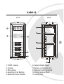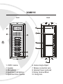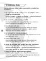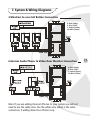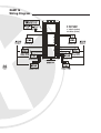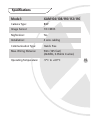
1
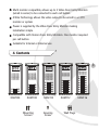
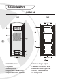
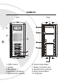
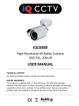
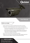
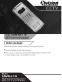
CCTV
Model: XAM104-116
B/W Multi Apartment Entry Camera
with 4, 8,10, 12 or 16 Call Buttons
Before you begin
• Please unpack the box carefully and identify that all the parts are present.
• Do not cut the cables, this will void the warranty.
• Make sure you use only the recommended power supply. Damage caused to the unit by
incorrect voltage or wiring is not covered by the warranty.
Model:
XAM104-116
B/W Multi Apartment Entry Camera
with 4, 8,10, 12 or 16 Call Buttons
Thank you for purchasing this Xvision Video Door Entry Phone/Monitor.
Before operating this product, please read this instruction manual
carefully.
1. Safety Precautions
2. Product Description
2
The XAM104, 108, 110, 112 & 116 are an excellent value range of B/W
Multi Apartment Cameras with multiple call buttons, designed for ease
of use and maximum reliability. They can be used together with any one
of the B/W Phone/Monitors or Intercom Handsets in the B/W Door Entry
Range. They include a 1/3” image sensor with Nightvision LEDs.
3. Features
4, 8, 10, 12 or 16 call buttons (depending on model chosen)
Designed for Flush mounting on a Wall
Stylish, durable aluminium casing
ID Panel for identifying call buttons to callers
Wide Viewing Angle and 1/3” image sensor ensures good quality
viewing of visitors
Multi monitor compatible, allows up to 3 Video Door Entry Monitors
(wired in series) to be connected to each call button
4 Wire Technology allows the video output to be wired to a CCTV
monitor or system
Power is supplied by the Video Door Entry Monitor making
installation simple
Compatible with Xvision Door Entry Monitors. One monitor required
per call button
Suitable for Internal or External use
4. Contents
3
XAM104
XAM108
Mounting
Screws
XAM110
Securing
Screw
XAM112
Wall Plugs
XAM116
5. Controls & Parts
XAM104
Front
Back
4
1. CMOS Camera
2. Speaker
3. Microphone
4. Apartment Call Buttons
5. Apartment Door Number
6. Camera Angle Adjust
7. Release connection wire
8. External Power (optional)
9. Wiring Terminal Block
10. Fixing hole
XAM108
Front
Back
5
1. CMOS Camera
2. Speaker
3. Microphone
4. Apartment Call Buttons
5. Apartment Door Number
6. Camera Angle Adjust
7. Release connection wire
8. External Power (optional)
9. Wiring Terminal Block
10. Fixing hole
XAM110
Front
Back
6
1. CMOS Camera
2. Speaker
3. Microphone
4. Apartment Call Buttons
5. Apartment Door Number
6. Camera Angle Adjust
7. Release connection wire
8. External Power (optional)
9. Wiring Terminal Block
10. Fixing hole
XAM112
Front
Back
7
1. CMOS Camera
2. Speaker
3. Microphone
4. Apartment Call Buttons
5. Apartment Door Number
6. Camera Angle Adjust
7. Release connection wire
8. External Power (optional)
9. Wiring Terminal Block
10. Fixing hole
XAM116
Front
Back
8
1. CMOS Camera
2. Speaker
3. Microphone
4. Apartment Call Buttons
5. Apartment Door Number
6. Camera Angle Adjust
7. Release connection wire
8. External Power (optional)
9. Wiring Terminal Block
10. Fixing hole
6. Installation
1. Choose a suitable location to mount the Multi Apartment Entry
Camera. The handset should be mounted 1.50 to 1.70m from floor
level.
2. Fix the mounting bracket to the wall.
3. Attach the unit to the mounting bracket.
4. Attach the main body of the unit to the back cover and open the
small covers on the two sides. Insert the securing screw into the into
the hole in the tab to hold the unit in place.
Note: You can use a small screw driver to prize open the covers on the
two sides of the unit. Be careful not to scratch the main cover.
The same installation method applies for all the Multi Apartment Entry
Camera Units.
9
6. Installation- Notes
Use the following points to help you complete a trouble free
installation:
1. Do not position the door entry camera in sunlight or where
it may be affected by rain
The unit is suitable for external use, however it should be mounted in
an area where it is sheltered from rain and snow.
2. Do not aim the camera at intense light
Viewing intense light, such as a spotlight may cause a bloom or
smear. A vertical stripe may appear on the screen.
10
3. Treat the unit with care
Do not disassemble the unit as you may damage the internal
components. Dropping the unit or banging it against another
object may cause the unit to malfunction.
4. Do not touch the internal components
Do not touch the internal components of the unit. There are no user
serviceable parts inside.
5. Avoid contact with water
Install the unit where it can be kept dry. If the units gets wet
accidentally, turn off the power and contact your dealer.
6. Install the unit away from possible sources of interference
Avoid running cables close to other wiring installations or
electrical equipment, such as a TV. These may cause interference to
video images. Relocate the cabling or find a new location.
7. Check the ambient temperature and humidity
Avoid using the camera in an area where the temperatures are
outside the range specified. The quality of images may deteriorate
and internal components may be affected.
7. System & Wiring Diagrams
3 Monitors to one Call Button Connection
R: Red (Audio)
B: Blue (GND)
Y: Yellow (Power)
W: White (Video)
Intercom Audio Phone to Video Door Monitor Connection
R: Red (Audio)
B: Blue (GND)
Y: Yellow (Power)
W: White (Video)
Note: If you are adding Intercom Phones to your system you will not
need to use the white wire. Use the white wire, which is the video
connection, if adding Video Door Phones only.
11
XAM104
Wiring Diagram
R: Red (Audio)
B: Blue (GND)
Y: Yellow (Power)
W: White (Video)
12
XAM108
Wiring Diagram
R: Red (Audio)
B: Blue (GND)
Y: Yellow (Power)
W: White (Video)
XAM110
Wiring Diagram
R: Red (Audio)
B: Blue (GND)
Y: Yellow (Power)
W: White (Video)
13
XAM112
Wiring Diagram
R: Red (Audio)
B: Blue (GND)
Y: Yellow (Power)
W: White (Video)
XAM116
Wiring Diagram
R: Red (Audio)
B: Blue (GND)
Y: Yellow (Power)
W: White (Video)
14
Specifications
Model:
XAM104/108/110/112/116
Camera Type:
B/W
Image Sensor:
1/3 CMOS
Nightvision:
Yes
Installation:
4 wire cabling
Communication Type:
Hands Free
Max. Wiring Distance:
50m (165 feet)
(22AWG, 0.65mm 4 wires)
Operating Temperature:
-5°C to +60°C
15
CCTV
TECHNICAL SUPPORT:
For Technical Support for any Xvision product please contact your local
distributor.
LIMITED WARRANTY:
This product is supplied with a 1 Year warranty. The Warranty excludes
products that have been misused, (including accidental damage) and
damage caused by normal wear and tear. In the unlikely event that you
encounter a problem with this product, it should be returned to the
place of purchase.
16
Manufactured exclusively for:
Xvision (Europe) Group,
Head Office: London, U.K.
Email: [email protected]
Web: www.x-vision.co.uk