1
RHF1201
5.4
User manual
Design examples
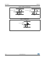
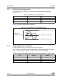
The RHF1201 is designed to obtain optimum performance when driven on differential inputs
with a differential amplitude of two volts peak-to-peak (2 Vpp). This is the result of 1 Vpp on
the Vin and Vinb inputs in phase opposition (Figure 17).
For all input frequencies, it is mandatory to add a capacitor on the PCB (between Vin
and Vinb) to cut the HF noise. The lower the frequency, the higher the capacitor.
The RHF1201 is specifically designed to meet sampling requirements for intermediate
frequency (IF) input signals. In particular, the track-and-hold in the first stage of the pipeline
is designed to minimize the linearity limitations as the analog frequency increases.
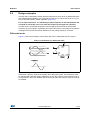
Differential mode
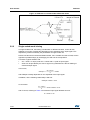
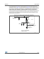
Figure 17 shows an example of how to drive RHF1201 in differential and DC coupled.
Figure 17. Example 2 Vpp differential input
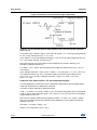
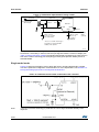
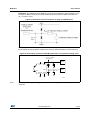
Figure 18 shows an isolated differential input solution. The input signal is fed to the
transformer’s primary, while the secondary drives both ADC inputs. The transformer must
be matched with generator output impedance: 50 Ω in this case for proper matching with a
50 Ω generator. The tracks between the secondary and Vin and Vinb pins must be as short
as possible.
DocID012585 Rev 7
21/38
38