1
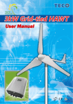
CARLO GAVAZZI
Automation
Components
Mistral3K
Aeolic Generator
User Manual
Table of Contents
Safety of Life . . . . . . . . . . . . . . . . . . . . . . . . . . . . . . . . . . . . . . . . . . . . . . . . . . . . . . . . . . . 2
Safety of Installation . . . . . . . . . . . . . . . . . . . . . . . . . . . . . . . . . . . . . . . . . . . . . . . . . . . . . 3
Safety of Machinery. . . . . . . . . . . . . . . . . . . . . . . . . . . . . . . . . . . . . . . . . . . . . . . . . . . . . . 4
Chapter 1 Wind Power System . . . . . . . . . . . . . . . . . . . . . . . . . . . . . . . . . . . . . . . . . . . . 5
1-1
Wind Turbine Specifications . . . . . . . . . . . . . . . . . . . . . . . . . . . . . . . . . . . . . . . 5
1-2
Wind Turbine Description . . . . . . . . . . . . . . . . . . . . . . . . . . . . . . . . . . . . . . . . . 7
1-3
Grid-tied Wind Power Inverter Specifications . . . . . . . . . . . . . . . . . . . . . . . . . 8
1-4
Grid-tied Wind Power Inverter Description. . . . . . . . . . . . . . . . . . . . . . . . . . . . 9
1-5
Wind Power System Operation. . . . . . . . . . . . . . . . . . . . . . . . . . . . . . . . . . . . . 9
Chapter 2 Installation of Wind Power System . . . . . . . . . . . . . . . . . . . . . . . . . . . . . . . 11
2-1
Installation of Wind Turbine. . . . . . . . . . . . . . . . . . . . . . . . . . . . . . . . . . . . . . . 11
2-2
Installation of Grid-tied Wind Power Inverter . . . . . . . . . . . . . . . . . . . . . . . . . 15
2-3
Braking Box. . . . . . . . . . . . . . . . . . . . . . . . . . . . . . . . . . . . . . . . . . . . . . . . . . . 18
Chapter 3 Wind Power System Operation . . . . . . . . . . . . . . . . . . . . . . . . . . . . . . . . . . 23
3-1
Start Test . . . . . . . . . . . . . . . . . . . . . . . . . . . . . . . . . . . . . . . . . . . . . . . . . . . . . 23
3-2
Instruction of Grid-tied Wind Power Inverter . . . . . . . . . . . . . . . . . . . . . . . . . 23
Chapter 4 Protection . . . . . . . . . . . . . . . . . . . . . . . . . . . . . . . . . . . . . . . . . . . . . . . . . . . 25
4-1
Electromagnetic Brake Protection . . . . . . . . . . . . . . . . . . . . . . . . . . . . . . . . . 25
4-2
High Wind Protection(Furl Protection) . . . . . . . . . . . . . . . . . . . . . . . . . . . . . . 25
Chapter 5 Troubleshooting. . . . . . . . . . . . . . . . . . . . . . . . . . . . . . . . . . . . . . . . . . . . . . . 26
Chapter 6 Spare Parts List. . . . . . . . . . . . . . . . . . . . . . . . . . . . . . . . . . . . . . . . . . . . . . . 27
Index of manual revision
Revision
Date
Description
Executors
Rev_00
2009/01/03
First release
AS jc
Rev_01
2009/03/23
Release 1.02
AS cb jc
Rev_02
2009/04/01
Review wiring examples
AS jc
Specifications are subject to change without notice. Pictures are just an example. For special features and/or customization, please ask to our sales network. 010409
1
Please read this manual carefully and follow its instructions and recommendations, this
manual will assist you to operate this renewable energy system safely and pleasantly.
Safety of Life
01. Never touch any switch with wet hands.
02. Always check and make sure there are no obstacles or people near the machine’s movable
parts before operating the machine.
03. Cover your hair and do not wear loose clothing or jewelry to avoid becoming tangled or
caught in the machine.
04. Never touch or stand near the moving parts of the machine while the machine is operating.
Serious injury may occur by being caught between the moving parts.
05. Please avoid approaching the wind turbine. The high voltage of the turbine or inverter may
cause casualty or electrical shock if touch, or you may get burn due to electrical short circuit.
06. Always turn off the power before performing maintenance and inspection. Maintenance and
inspection inside the cover is especially dangerous.
07. Do not climb on the machine unless absolutely necessary.
08. Machine and electricity of a renewable energy system contains certain dangers, it may
cause death or injury while misuse the machine.
09. Improper construction work may weaken the strength of tower or support frame structure,
and result in casualty, death or losses of property.
10. Lack of maintenance in any part of the system, improper operation of the wind energy power
system and loose of components or parts may cause casualty, death or losses of property.
11. Please avoiding approaching the blade due to high speed rotary blade due to the high
possibility causing casualty or death, please shut off the system before performing
maintenance.
12. Do not lean on the machine while the machine is operating. Leaning on the covers can be
very dangerous.
13. If the turbine becomes loud or a loud sound is heard in tower, the system must be shut off
immediately. A loud turbine or part will damage the turbine body soon enough, and it is
possible to cause the tower to lean or to collapse and results in casualty.
14. An untrained personnel or a person without adequate safety equipment is highly restricted
to climb the tower. It is highly restricted to climb the tower before the blade of wind turbine
stop as well.
15. High voltage system (any contact point of the primary side of the system) indicates danger
of shock and fatal harm. All the construction work and maintenance of high voltage system
line must be performed and executed by professional personnel.
16. To avoid danger, construction work and wiring must be done by professional personnel.
2
Specifications are subject to change without notice. Pictures are just an example. For special features and/or customization, please ask to our sales network. 010409
Important! Carlo GAVAZZI does not take any responsability for any injury to persons or damage
to things both due to mis handling of the turbine or bad electrical connection of the products.
Safety of Installation
01. Leave space for maintenance. Install the machine so that the covers of the machine can
be opened without interference.
02. Make sure that the ground strong enough to support the machine.
03. Only an authorized electrical technician should perform work with the power cable connections.
04. Make sure that all bolts are tightened securely.
05. Make sure that all related hoses are connected secure.
06. The machine should be operated by one, well-trained person only. Injury can occur if more
than one person operates the machine. If more than one operator is absolutely necessary,
all involved operators must cooperate and be able to communicate.
07. Never start machine operation without the safety devices in place.
08. Construction work of tower or supporting frame must be done by professional installation
personnel, electrical wire must be qualified product and wiring work be done by
professional and qualified personnel. Construction work, wiring products and electrical
installation personnel must be in accordance with construction regulation standard.
09. Related permission certificates and engineering certificates are required for safe
installation. Location of tower, tower and tower foundation must be professionally
designed. Soil and wind field status must be put into consideration when selecting a
location. Tower must keep far away from buildings, neighboring properties or electrical
power lines. Do not attempt to climb the tower, only experienced personnel with adequate
safety equipment is allowed to climb the tower. It is recommended that when installing
tower, keep it away from buildings and electrical power lines for at least 100 meters
(300ft).
10. The construction and wiring process must be in accordance with electrical engineering
regulations of the resident country.
11. Never remove the covers unless absolutely necessary.
12. These equipments must have proper heat elimination function, air current jam may bring
fire disaster.
Specifications are subject to change without notice. Pictures are just an example. For special features and/or customization, please ask to our sales network. 010409
3
Safety of Machinery
01. Never remove the inverter covers unless absolutely necessary, and after the device is
turned off.
02. Never put any tools or instruments on the machine operation panel or on any machine part.
03. Be careful not to operate the wrong switch. Visually check the switches on the operation
panel before operating them.
04. Never change the parameter setting without consulting your local representative. If
changed inadvertently, some parameters will cancel interlock setting.
05. Wiring work for 200 VAC or higher voltage circuits must be performed only by an
authorized electrical technician.
06. Do not open the door of the electrical cabinet or the operation panel unless absolutely
necessary. Opening the door allows dust, foreign matter, and moisture to enter the
enclosure and can cause machine malfunctions.
07. Carry out daily, monthly, and semi-annual inspection as specified in this operation manual.
08. Clean the machine so that any abnormalities can be found easily.
09. The output wiring of wind power system may cause a low voltage shock whenever the
rotor is turning. Caution must be implemented at all times to avoid electrical shock.
10. Please do not install wind power system near cliffs or precipices or on sharp hills such
that the wind does not travel horizontally through the rotor.
11. The weight distribution of the system is specially balanced. Any change of the system weight
and balance, especially the tail, may cause malfunction of the Furl Protection Function.
12. Additional Electromagnetic Brake Protection is provided by the electronic system
controller, please refer to the electronic system controller manual for more details.
4
Specifications are subject to change without notice. Pictures are just an example. For special features and/or customization, please ask to our sales network. 010409
Chapter 1
Wind Power System
This system is the latest small wind power system designed to provide electricity which can
be used on several different type applications, such as batteries charging, or stand alone
remote electrical power supply system. Furthermore, with the additional Grid-tied Wind
Power Inverter, the wind power system can also be connected to the power grid.
1-1 Wind Turbine Specifications
The wind turbine consists of a 2.6 meter rotor system and a generator which is 35cm in
diameter. The 58 kilogram wind turbine is rated at 3000W @ 13.5m/s wind speed.
The wind turbine features superior low start-up wind speed blade design which provides great
performance, very high system efficiency, and low noise. For tower installation procedures,
please refer to the Chapter 2-1.
Wind Turbine Specifications
Rotor diameter
Total weight
2.6m/s
58kg
Start-up wind Speed
Furl Protection
2.5m/s
Start @ 13.5m/s
Cut-in wind Speed
Cut-out wind Speed 13.5m/s
2.8m/s
Rated wind Speed
Rated output
13.5m/s
3kW @ 13.5m/s
Rotor RPM
145 - 780rpm
Survival Wind Speed
50m/s
Maximum Power
3kW
Generator Output (three types) 3phase AC 30V-240V
Generator
3phase permanent magnet generator of an 18 poles structure
Each wind turbine has a MSN (Manufacture Serial Number) printed on the tower mount. In
addition, all three blades also have their own BSN (Blade Serial Number) printed at the blade
root. The MSN/BSN are also written on the delivery box.
We recommend writing it here as well:
The wind turbine system MSN:____________________
Blade BSNs :1. ___________________2.____________________3. ___________________
Date of Installation : __________________
Specifications are subject to change without notice. Pictures are just an example. For special features and/or customization, please ask to our sales network. 010409
5
Blades
Central body Assembly
Tail fin
Spinner
Nacelle
Generator casing
Tail boom
Tower mount adapter
Figure 1 Wind turbine assembly
A. Blades
B. Generator
C. Nacelle and Tail Assembly
D. Complete Assembly
Figure 2 Wind turbine main components
6
Specifications are subject to change without notice. Pictures are just an example. For special features and/or customization, please ask to our sales network. 010409
1-2 Wind Turbine Description
The main components of the wind turbine are shown as for Figure 2.
A. Blades / Rotor System
The rotor system consists of three glass/carbon fiber blades. The glass/carbon fiber blades are
structurally strong because there are extra glass/carbon reinforcing fibers layers that hold the
full length of the blade. The blades absorb the energy of the wind and convert them into
rotational forces that drive the generator. The rotor system includes three blades because three
blades will provide excellent balance between the cost and efficiency and can run much
smoother than two blades rotor.
Warning!
The composites blades are very strong in tension, but they are susceptible to impact damage.
They should be handled carefully to avoid any impact during installation.
B. Generator
The generator converts the rotational energy of the blade/rotor system into electricity. It is a
3-phase permanent magnet generator of an 18 poles structure. The generator is a completely
new design for the wind power system and it produces power even at low rotating speeds.
The output of the generator is three-phase variable-frequency alternating current (AC), and it
can be rectified to direct current or connected to power grid through a grid-tied device.
C. Central Body Assembly
The central body assembly consists of the blade hub, generator casing, and the nacelle. It is
the main structural “backbone” of the rotor system, the generator, the yaw bearings, slip-ring
assembly, the tail, and the tower mount. The yaw bearings allow the wind turbine to turn
around the top of the tower in order to head the wind. The slip-ring assembly is the electrical
mean to connect the movable part of the wind turbine to the fixed tower wiring. The slip-rings
and yaw bearings are located inside the tower mount. The tower mount attaches wind power
system to the top of the tower through the tower mount adapter.
D. Tail Assembly and High-Wind Protect (Furl Protect) Function
The tail assembly, which includes the tail boom and tail fin, will keep the generator Assembly
and rotor facing to wind at wind speeds less than about 13.5m/s. At wind speeds reaching
approximately 13.5m/s, the High-Wind Protect function actives and turns the rotor partially
away from the wind to prevent the rotor over-speed.. That allows the turbine to continue to
generate electrical power before it reaching the safety shutdown control point in high winds.
When the wind speed slower, the High-Wind Protect function will inactive and turn the turbine
back to the heading wind position.
Specifications are subject to change without notice. Pictures are just an example. For special features and/or customization, please ask to our sales network. 010409
7
1-3
Grid-tied Wind Power Inverter Specifications
•
•
•
•
•
•
•
•
Input data
DSP based fully digital control
Converter ability 3.0kW/240V 50/60Hz
High efficiency: 95% above.
Maximum Power Point Tracking function
Anti-Islanding
LCD displays generation data & status
High power conversion efficiency
Easy installation
Output data
AC connection
Voltage range
Operating voltage range
Max. current
3-phase
0...200VAC
30...180VAC
18A
Environmental data
Operating temperature -20...+40°C
Storage temperature -25...+80°C
Coooling
Natural convenction
Humidity
0...95%
(non condensing)
Installation location Indoor
Protection degree
IP43
AC connection
1-phase
Nominal power
3kW
Max. power
3.6kW
AC voltage
230VAC ±5%
Frequency
50Hz
Max. current
14A
Power factor
>0.99 @ full load
Distortion factor THD <3%
Max. efficiency
>95%
General data
Protection device
Grid monitoring system
Anti-islanding monitoring Yes
Mechanical Data
Standard Norms and Certifications
User interface
LCD data display
Dimensions (HxWxD) 535x360x200mm
Weight
22.5kg
UNI-EN Standard
VDE Standard
Certifications
1-4
EN50178, EC62103
VDE0126-1-1
CE: MD, LVD and EMC
Grid-tied Wind Power Inverter Description
This product is a wind energy utility grid-tied system. Single-phase grid-tied wind power
inverter is different from traditional stand- alone type wind energy inverter, it does not need
additional expensive and large space required energy storage battery, hence free from
considerable battery maintenance expense. It efficiently converts power generated from wind
turbine, high efficiently in to AC power to feed into grid, having the direct benefit of power
generation and energy saving.
8
Specifications are subject to change without notice. Pictures are just an example. For special features and/or customization, please ask to our sales network. 010409
1-5
Wind Power System Operation
A. Normal Operation
The generator of wind power system should begin to generate electricity when the wind
speed reaches approximately 3m/s. The rotor rotational speed will increase with higher wind
speed. The generator output is proportional to the third power of wind speed. Please
refer to Figure 4 for the relationship between power output and wind speed.
The inverter relays sequence (a1, a2 and b1, b2) after the start up is described in figure 3.
WTI software version is V1.02+Figure 2
a1,a2
No SB
close(on)
SB
No SB
SB
open(off)
WTI
WTI
WTI
b1,b2
power off power on activate
t (sec)
close(on)
RB
open(off)
RB
No RB
several
second
t (sec)
Figure 3 Event timing Chart of WTI software versionV1.02
Power (W)
The basic intention is to keep the wind turbine braked until the full functionality of the inverter is
warranty. After several seconds the relays are then energized allowing the wind turbine free to run.
Wind Speed (m/s)
Figure 4 Power Curve: Wind Speed vs. Power
Note
The operational wind speeds and performance in the manual assume the condition of sea-level
altitude, steady winds, and moderate temperatures. High altitude, hot temperatures, turbulence
and gusting winds will usually bring the system performance lower than expectation.
Specifications are subject to change without notice. Pictures are just an example. For special features and/or customization, please ask to our sales network. 010409
9
B. High-Wind Protection (Furl Protection)
In case of high wind speeds, the High-Wind Protection Function system will protect the wind
turbine automatically. When furled, the rotor will turn away from the wind direction, the rotor
speed will reduce, and the power output of the turbine will be significantly reduced.
High-Wind Protection Function is an easy method to provide high wind speed protection. The
High-Wind Protection Function is based on basic physical relationship between the
aerodynamics, rotor, gravity, and the specially designed tail shape and weight balance of the
wind power system.
The High-Wind Protection Function is completely passive, so it is very reliable. But there is
one situation in the field that we have found it can disrupt the operation of High-Wind
Protection Function:
if the wind turbine is installed on a sharp hill or next to a cliff so that the wind can come up
through the rotor on an incline (e.g., from below; as opposed to horizontally) this will affect
furling and can produce higher peak outputs. We strongly recommend avoiding this situation.
Caution
The weight distribution of the system is specially balanced. Any change of the system weight
and balance, especially the tail, may cause malfunction of the High-Wind Protection Function.
Note
Additional Electromagnetic Brake Protection Function is provided by the electronic system
controller, please refer to Chapter 4 Protection.
10
Specifications are subject to change without notice. Pictures are just an example. For special features and/or customization, please ask to our sales network. 010409
Chapter 2
Installation of Wind Power System
Caution
•
To avoid danger, construction work and wiring must be done by professional personnel.
•
The construction and wiring process must be in accordance with electrical engineering
regulations.
•
Please read this manual carefully and follow its instructions and recommendations.
2-1
Installation of Wind Turbine
Parts and Accessories List:
There are three shipping boxes for a complete set of wind turbine. Details are as follows,
Boxes
Desciption
Dimensions (L x W x H)
Box 1
Box 2
Box 3
Central body and Accessories 68cm x 48.5cm x 35cm
Blades
123cm x 28cm x 36cm
Tail assembly
155cm x 48cm x 5.5cm
Weight
39.3kg
13.0kg
6.2kg
Before Installation, please check the packing for the following items:
No. Desciption
Specification
1
2
3
4
5
6
7
8
9
10
11
12
13
1.2m / Material: Glass + Carbon fiber
Permanent magnet synchronous generator
Material: Nylon + Glass fiber
Blade
Body
Spinner
Tail Fin Plug
Tail Fin
Stainless Steel
Stainless Steel
Stainless Steel
Stainless Steel
Stainless Steel
Stainless Steel
Stainless Steel
Stainless Steel
Screw
Nut
Flat Washer
Spring Washer
Screw
Nut
Washer
Screw
Material: Zinc-coated steel
Ø12mm x 60mm
Ø12mm
Ø12mm
Ø12mm
Ø8mm x 75mm
Ø8mm
Ø8mm
Ø12mm x 130mm
Specifications are subject to change without notice. Pictures are just an example. For special features and/or customization, please ask to our sales network. 010409
Q.ty
(pcs)
3
1
1
1
1
6
10
10
12
2
2
4
2
11
Wind Turbine Assembly Procedure :
(1) Fasten the three blades into the circular hub using two 12mm-diameter, 60mm-long bolts for
each blade. To refer Figure 5, firstly put one spring washer through the bolt, follow by one flat
washer, insert them through the blade and hub, put another spring washer through the protruding
part of the bolt, apply Loctite to the thread, and fasten with a nut. Press the spinner into the hub.
3
9
6
8
9
7
Figure 5 Assembly of blades and spinner
(2) Attach the tail assembly to the central body assembly using two 8mm-diameter bolts. To
refer Figure 6, firstly put one flat washer through the bolt, insert them through the tail and
nacelle, put another flat washer to the bolt, apply Loctite to the thread, and fasten with a nut.
10
8
8
11
Figure 6 Assembly of tail and tail plug
12
Specifications are subject to change without notice. Pictures are just an example. For special features and/or customization, please ask to our sales network. 010409
(3) Attach the wind turbine power output wires to the power cable with insulated heat shrunk
tube and straighten the cable. Put the supporting pole into the tower mount adapter using
two 12mm-diameter, 130mm-long bolts. To refer Figure 7, firstly put one flat washer
through the bolt, insert them through the adapter and pole, put another flat washer to the
Notice! Don’t PRESS or
bolt, apply Loctite to the thread, and fasten with two nuts. (
DAMAGE wires when assemble supporting pole)
7
8
8
13
Figure 6 Assembly of wind turbine and supporting pole
(4) Hoist the wind turbine and supporting pole into position, fasten the pre-installed foundation
bolts with nuts and apply Loctite to the thread to complete the installation.
Specifications are subject to change without notice. Pictures are just an example. For special features and/or customization, please ask to our sales network. 010409
13
Support Tower Suggestion
BILL OF MATERIALS
TOTAL
1
m3
5,83
unreinforced concrete
1700x1700x100
1
m3
0,29
concrete C25/30 for plinth
1500x1500x500
1
m3
1,13
concrete C25/30 for plinth
(ttx250x250)x250
1
m3
0,05
quarterdeck
4x1500x500
1
m2
3,00
quarterdeck
2ttx250x250
1
m2
0,39
reinforcement "a" (o14)
2340
14
kg
39,57
reinforcement "a" (o14)
2340
14
kg
39,57
reinforcement "b" (o10)
1860
4
kg
4,59
reinforcement "c" (o14)
2970
4
kg
14,35
reinforcement "d" (o12)
1810
3
kg
4,81
pleated hose o60
1200
1
m
1,20
concrete mix EmacoS55
o400x30
1
it
3,80
tie bars oM20
950
8
kg
18,74
washer M20
-
8
n
8,00
screw nut M20
-
2x8
n
16,00
plate th.25
o320
1
kg
15,78
plate th. 6
80x160
4
kg
2,41
tube o159 th. 6
5824
1
kg
131,76
plate th. 20
o159
1
kg
3,12
tube o88,9 th.7
131
1
kg
1,91
metal sheet th.2
240x80
1
kg
0,30
screw M6
-
2
n
2,00
Reinforcement d:
3 stØ12
n. 8 tie bars M20
Ø460
threaded tract
120
U.M.
2700x2700x800
Tube Ø159 - th.6
hot zinc-coated
L= 5820
25
750
Ø500
Reinforcement c:
2+2 stØ14
250
30
DIMENSION (mm) Q.TY
excavation
5820
6000
20 135
DESCRIPTION
670/700
500
440
a
a
a
100
a
a
a
140
100
a’
Unreinforced
concrete
a
100
1500
b
450
450
450
450
1440
Reinforcement a’: 7 + 7 Ø14
100
1440
a
a
a
a
a
a
a
450
a’
a
100
a’
a’
d
1440
1440
Reinforcement a: 7 + 7 Ø14
a’
a’
c
c
a’
c
Ø500
1500
c
a’
a’
450
450
Reinforcement b: 4Ø10
200
200
450
1460
14
Specifications are subject to change without notice. Pictures are just an example. For special features and/or customization, please ask to our sales network. 010409
2-2
Installation of Grid-tied Wind Power Inverter
Installation Procedure of Inverter:
Conditions
Do not operate the Inverter in an environment where the ambient temperature is outside the
limits given in the specifications of this manual. These inverter units are intended for use in a
temperature-controlled, indoor area free of conductive contaminants. Select a location that
will provide good air circulation for inverter at all times.
• Placement
Mounting the Grid-tied Inverter on the wall
01. The mounting background must be firm.
02. The ambient temperature must be between -20°C and +40°C.
03. Install at a shading roof, do not expose the inverter to direct sunlight.
04. Keep it in good ventilated situation; a minimum distance of 254mm (10”) must be clear
around the inverter.
05. The heat sink can reach a temperature of more than +80°C. The air circulation must be
sufficient for heat dissipation.
06. Provide a correct position of the inverter for mounting.
07. The inverter is mounted on the back side with the metal strap. (Figure 8)
08. Check mounting is firm.
09. Please ensure to install the grid-tied wind power inverter in a ventilated location. There
should be no any stack around one meter of its surrounding.
STEP 1: Heat dissipation
Keep a minimum distance of
203-304mm
(8-12”) clear around the inverter
STEP 2: Fix the metal strap
Fixed six screws
STEP 3: Hang up
STEP 4: Check it firm
Specifications are subject to change without notice. Pictures are just an example. For special features and/or customization, please ask to our sales network. 010409
15
fixed position
fixed position
fixed position
Figure 8 Metal strap of Inverter
Inputs/Outputs
Specifications
Figure 9 WTI3 product label
16
Specifications are subject to change without notice. Pictures are just an example. For special features and/or customization, please ask to our sales network. 010409
WT3
Wind Turbine
Load
Grid
Circuit breaker
Meter
WTI3
Wind Turbine
Inverter
AC Disconnect
WTB3
Wind Turbine
Braker
LA device
Circuit braker
WT Brake
Circuit breaker
L N
R S
T
PE
Figure 10 Wind Power System Wiring Description
Power Wire Size Selection
Please connect electrical wire according to each contact marked with description. Regulated wire
size as follows: See detailed wiring diagram in Figure 13.
AC output wire use a size at least 12AWG (or 4mm2) black copper wire.
Wind turbine wires use at least 12AWG (or 4mm2) and above copper wire, these wires to be of
different color in order to distinguish R, S, T 3phase power.
It is recommended to use 12AWG (or 4mm2) and above yellow/green copper wire on machine
housing earthing (grounding) wire.
Notice of Wiring
• Before wiring, please finish installation of the wind power inverter, meanwhile, check and
ensure that there is no fuse breaker of main distribution board is in close status.
• In order to ensure quality of electrical wiring. Please use a wire size recommended in this
manual and in accordance with wiring standard of electrical regulations.
•
Important! : The GREEN wire of wind turbine is neutral wiring output from generator, it’s for
special application. Please leave GREEN wire isolated, don’t wire it to any conductive goods.
Specifications are subject to change without notice. Pictures are just an example. For special features and/or customization, please ask to our sales network. 010409
17
2-3
Braking Box
Description
The typical configuration of the braking box and relative components are shown on figure 13.
Depending on wind speed and plant condition, the inverter drives two different electrical
brakes. Through the inverter outputs: a1, a2 and b1 and b2, the relays KM1-KM3 and KM4KM6 are switched ON or OFF in order to prevent any damage on turbine and inverter. One
brake is done by resistor R1-R3, and this is the dumping brake. If the wind is keeping an high
speed for a long period of time beside the dumping brake will turn on by mean inverter
outputs a1 and a2.
The braking box allows to apply a manual brake too through breakers QM2-QM3. These
manual brakes are independent from the brakes a1, a2, b1 and b2.
The QM1 breaker is the main breaker of Mistral3k system from the grid, it allows to switch off
the braking box and the inverter too.
20cm
40cm
WTB3
Mistral3K Braking Box
Max. input voltage (AC)
200V
Max. operating current (AC) 18A
Electrical specifications
Operating voltage range
20...200V
Operating temperature
-20°...+50°C
WTB3 - Mistral3K Braking Box
70cm
S/N:
0 911000 000306
EAN:
8 032973 927574
Serial number
EAN code
Degree of Protection
IP65
Carlo Gavazzi
Via Milano 13,
IT-20020 Lainate (MI)
www.carlogavazzi.com/ac
Made in: Italy
Figure 11 WTB3 Braking box product label
18
Figure 12 WTB3 Dimensions
Specifications are subject to change without notice. Pictures are just an example. For special features and/or customization, please ask to our sales network. 010409
L
N
L1
N1
3
1
KM1
4
2
5
6
7
8
1
2
3
4
8
Specifications are subject to change without notice. Pictures are just an example. For special features and/or customization, please ask to our sales network. 010409
PE
L
N
3
4
7
3
4
7
8
5
6
b1
7
8
b2
C1
WTI3
Grid tied inverter
a2
KM3
a1
5
6
1
2
1
2
R
S
T
3
4
3
4
5
6
7
8
KM4
T
S
R
1
2
5
6
7
8
K2
1
2
8
+
5
6
7
-
12VDC
KM5
3
4
1
2
3
4
5
6
7
8
3Ω/1kW
KM6
R3
R S T
C2
QM2
TB
QM3
091100000002
Manual
Breakers
Pole
junction
box
T
1
2
5
6
R2
WT3
Wind generator
S
Red wire
K1
KM2
-
12VDC
+
R1
Dumping resistors
MISTRAL3K BRAKING BOX v.02
R
Black wire
TB
GD1
DC Supply
SPD12051
QM1
TB
220V - 50Hz
Green wire
Yellow wire
Figure 13 Detailed wiring diagram
19
AWG
5
6
7
8
Section
(mm2)
16.77
13.30
10.55
8.37
AWG to Metric Wire Size Conversion Chart
Section
Section
AWG
AWG
2
(mm )
(mm2)
9
6.63
13
2.63
10
5.26
14
2.08
11
4.17
15
1.65
12
3.31
16
1.31
AWG
17
18
-
Section
(mm2)
1.04
0.82
-
Installation Procedure of Electrical Wire Control Box
01. When wiring, it is not necessary to open top cover of wind power inverter, ensure wiring
is fixed well and there is no danger of coming loose.
02. As shown on Figure 13, there are nine wires from wind power inverter, they are R, S, T, L, N (12AWG),
and a1, a2 (16AWG) short brake signal contact and b1, b2 (16AWG) resistor brake contact.
03. Wind turbine output R,S,T wire is connected respectively to manual brake switch, automatic
brake switch and three relays’ C contact then finally connected to wind power inverter.
(The GREEN wire of wind turbine is neutral wiring output from generator, it’s for special
application. Please leave GREEN wire isolated, don’t wire it to any conductive goods.)
04. The terminal block (European type) as for attachment is connected respectively to a1, a2,
b1, b2 contact.
05. a1 and a2 connected to signal of automatic short circuit brake switch, b1 and b2
connected to signal of automatic resistor brake switch.
06. AC output is connected to connected to utility through bi-directional wattmeter.
07. Grounding wire (PE) connected to wind power inverter and system grounding, please
avoid connecting grounding wire with main line and ensure grounding is properly done.
08. When adopting the third kind grounding, grounding resistor must be less then 10Ω.
09. Brake Resistor consists of three 3Ω/1kW; Y connection is connected to three relay b
contact respectively.
10. Caution! When resistor brake occurs, it will cause heat. Installation location must be in a
ventilated place.
11. Suggestion: L,N go through 1:1 isolation transformer to utility 220V/(50Hz or 60Hz).
Recommended specifications
01. Automatic short circuit brake switch: Consists of an electromagnetic switch. Main contact
stands 35A and above, coil start voltage 220V.
02. Automatic resistor brake switch: Consists of three relays, each relay stands 30A and
above, coil start voltage 220V.
03. Resistor box: Consists of three 3Ω/1KW for Y connection.
04. Lightning device: Capacity of lightning device is related to distance of wind turbine and
power distribution board INVERTER, please refer to electrical engineering regulations.
20
Specifications are subject to change without notice. Pictures are just an example. For special features and/or customization, please ask to our sales network. 010409
Wiring Description of Inverter
Loose six screws under the Inverter (as the red circle), after open it, there are two terminal
block and node label.
L N PE
R S T
L and N are connected to utility AC power. R, S and T are connected to Wind turbine AC output.
PE is grounding wire.
The wire connected to L is recommended to use 12 AWG (4mm2) and above. Suggest using brown color.
The wire connected to N is recommended to use 12 AWG (4mm2) and above. Suggest using blue color.
The wire connected to R is recommended to use 12 AWG (4mm2) and above. Suggest using red color.
The wire connected to S is recommended to use 12 AWG (4mm2) and above. Suggest using white color.
The wire connected to T is recommended to use 12 AWG (4mm2) and above. Suggest using black color.
The wire connected to PE is recommended to use 12 AWG (4mm2) and above. Suggest using yellow/
green color.
Wiring show as below figure:
L
brown
brown
N PE
R
blue yellow/green red
blue
yellow
/green
S
T
gray black
red
black
gray
Specifications are subject to change without notice. Pictures are just an example. For special features and/or customization, please ask to our sales network. 010409
21
The brown and blue wires gone through left spiral exclusive socket, connected tightly to L,N
terminal respectively. The green wires gone through medium spiral exclusive socket,
connected tightly to PE terminal. The red, white and black wires gone through right spiral
exclusive socket, connected tightly to R,S and T terminal. Then lock six screws.
Show as below figure:
gray
brown
blue
yellow/
green
red
brow blue yellow/
green
22
black
red black
gray
Specifications are subject to change without notice. Pictures are just an example. For special features and/or customization, please ask to our sales network. 010409
Chapter 3
Wind Power System Operation
3-1
Start Test
01. Ensure input voltage is within rated range by measuring the voltage on the input line.
02. Turn on the Main Breaker of Control Box, ensure utility voltage and frequency is within
normal range.
03. Confirm the manual brake switch(NFB2,NFB3) turned to OFF.
04. Wind power inverter goes to switch-on screen, it will take a few minutes for the machine
to do self-test and confirmation of utility voltage and frequency.
05. After output rated working range is confirmed, the wind turbine system will start to feed
power to the utility. Then, the system operates automatically.
3-2
Instruction of Grid-tied Wind Power Inverter
MISTRAL3K
Start / Close wind power inverter
Switch [ON/OFF] to start/close wind power inverter. If [ON/OFF] is not pressed down,
wind power inverter will automatically detect system, if the system works normally for 3
minutes, it will start to work automatically
Close wind power inverter
Press down [ON/OFF] for 2 seconds, buzzer sounds two short “beep” tone, wind
power inverter will stay in standby, if [ON/OFF] is not pressed down again or power not
re-started, the inverter will stay in standby.
Start wind power inverter
Press down [ON/OFF] for 3 seconds, buzzer sounds a long “beep” tone, the inverter
has been started. If the whole system of utility and wind turbine is under normal
condition, LCD will display [Waiting…]. If wind turbine produce energy to wind power
inverter, inverter will begin conversion suitable energy to utility and wind turbine system
operation normally. If wind energy isn’t enough, there is no energy output, and LCD will
display [Low wind].
Default of wind power inverter will lock button key, if you need to look up internal parameter, [UP] and [DOWN] key must be pressed at the same time, buzzer will then
sound two short “beep” tones, the locking of button key has been released.
Shift-up key
Shift-up key[UP] indicates cyclical moving upwards, display respectively
Input power (Pi)
Input voltage/current (Vw/Iw)
Output power (Po)
Output voltage/current (Vs/Is)
Shift-down key
Shift-down key[DOWN] indicates cyclical moving downwards, display respectively:
Input power (Pi)
Output voltage/current (Vs/Is)
Output power (Po)
Input
voltage/current (Vw/Iw)
Specifications are subject to change without notice. Pictures are just an example. For special features and/or customization, please ask to our sales network. 010409
23
LCD Display List
LCD display
(Brand Name)
Discription
Display brand name.
(Model Number)
Vx.x
Display model number and Vx.x: firmware version.
Waiting…
LOW_WIND
record_No=xx
The status of wind turbine system is normally, waiting for wind energy
feed-in, about 30sec.
When wind speed below 2.8m/sec, wind energy isn’t enough to feedin grid. The wind power inverter no power output.
To show system fault record recently. When system is malfunction,
there’ll show corresponding fault record. If system power is off, the
fault record will reset.
Vs=xxxV
Is=xx.xA
Vs=xxxV: grid-tied voltage value(V).
Is= xx.xA: grid-tied current value(A).
Po=xxxxW
Wind power inverter output power into grid(W).
Vw=xxxV
Iw=xx.xA
Vw=xxxV: Wind power inverter internal DC bus voltage value(V).
Iw= xx.xA: Wind power inverter internal DC bus current value(A).
Pi=xxxxW
The wind power output from wind turbine, and feed-in wind power inverter (W).
24
Specifications are subject to change without notice. Pictures are just an example. For special features and/or customization, please ask to our sales network. 010409
Chapter 4
Protection
4-1
Electromagnetic Brake Protection
This wind turbine system has two kind of electromagnetic brake protection function:
Resistor and Short-circuit Brake Protection. Using wind power inverter and control box to
perform this protection function.
01. Resistor Brake Protection:
When wind speed exceeds 13.5m/s, system will start resistor brake protection function.
Then wind turbine will slow down even stop. When wind speed is lower than 10m/s, system
will disable resistor brake protection function and wind turbine will operate normally.
02. Short Circuit Brake Protection: There are three conditions to perform this function.
A. If resistor brake occurs continuously three times within 10 minutes, after 30 seconds
upon the third time resistor brake occurs, short circuit brake actives for 2 minutes.
B. If wind turbine rotational speed goes up after resistor brake active, after 30 seconds
upon resistor brake occurs, short circuit brake actives for 2 minutes.
C. If short circuit brake occurs continuously three times within 30 minutes, the third time
short circuit brake will stay for 60 minutes.
4-2
High Wind Protection (Furl Protection)
The tail assembly, which includes the tail boom and tail fin, will keep the generator Assembly
and rotor facing to wind at wind speeds less than about 13.5m/s. At wind speeds reaching
approximately 13.5m/s, the High Wind Protect (Furl Protect) function actives and turns the
rotor partially away from the wind to prevent the rotor over-speed. That allows the turbine to
continue to generate electrical power before it reaching the safety shutdown control point in
high winds. When the wind speed slower, the High-Wind Protect function will inactive and
turn the turbine back to the heading wind position.
Specifications are subject to change without notice. Pictures are just an example. For special features and/or customization, please ask to our sales network. 010409
25
Chapter 5
Troubleshooting
This chapter description fault code of wind power inverter and inspection method.
Code
Display Message
Cause
2
UTILITY FAULT
Utility power
abnormal
3
DC VOLTS FAULT
9
Current error
10
OVER Temp
12
Line freq error
13
OVER WG ERROR
14
OVER Pout
15
DC V FAULT
16
Braking…R
17
Braking…S
23
GRID Vrms error
26
GRID Idc error
30
Leakage Current
41
UTILITY DET F
26
Inspection
• Check the connection between
Inverter and utility.
• Check utility voltage status.
Input Voltage is too
• Wind speed too high cause over
high
voltage.
Output current
• Check utility frequency and
abnormal
voltage status.
• Was heatsink blocked or not?
Over temperature
• Did the Inverter placed at
protection
ventilation position?
• Check the connection between
Grid frequency
Inverter and utility.
abnormal
• Check utility frequency status.
• Wind speed too high cause over
WT over speed
voltage.
• Inverter tripped, it’ll automatic
Over Load
reset in a while.
• Was wind speed too high cause
Surge Voltage to high
over voltage? The DC capacitor
maybe burn out already.
• The resistor brake function actives
Braking by resistor
now.
Braking by short
• The short circuit brake function
circuit
actives now.
Utility voltage too
• Was utility voltage over 10%
high
normal voltage in a short time?
• Check the connection between
DC offset current to
Inverter and utility. Was there
grid>1A
connected other load?
• Were electrical wire broken
somewhere?
Input device leakage
• Does the impedance too low
current too high
between inverter case and wind
generator coil?
• Check the connection between
Frequency over range
Inverter and utility.
• Check utility frequency status.
Specifications are subject to change without notice. Pictures are just an example. For special features and/or customization, please ask to our sales network. 010409
Chapter 6
Spare Parts List
Code
Product Description
TW_BLADE
Mistral3k Wind Turbine Blade
TW_NACELLE
Mistral3k Wind Turbine Nacelle
TW_SPINNER
Mistral3k Wind Turbine Spinner
TW_TAIL
Mistral3k Wind Turbine Tail
WTI3
Mistral3k Inverter
WTB3
Mistral3K Braking Box
Specifications are subject to change without notice. Pictures are just an example. For special features and/or customization, please ask to our sales network. 010409
27
OUR SALES NETWORK IN EUROPE
AUSTRIA - Carlo Gavazzi GmbH
Ketzergasse 374, A-1230 Wien
Tel: +43 1 888 4112
Fax: +43 1 889 10 53
[email protected]
FRANCE - Carlo Gavazzi Sarl
Zac de Paris Nord II, 69, rue de la Belle
Etoile, F-95956 Roissy CDG Cedex
Tel: +33 1 49 38 98 60
Fax: +33 1 48 63 27 43
[email protected]
BELGIUM - Carlo Gavazzi NV/SA
Schaarbeeklei 213/3, B-1800 Vilvoorde
Tel: +32 2 257 4120
Fax: +32 2 257 41 25
[email protected]
DENMARK - Carlo Gavazzi Handel A/S
Over Hadstenvej 38, DK-8370 Hadsten
Tel: +45 89 60 6100
Fax: +45 86 98 15 30
[email protected]
FINLAND - Carlo Gavazzi OY AB
Petaksentie 2-4, FI-00661 Helsinki
Tel: +358 9 756 2000
Fax: +358 9 756 20010
[email protected]
GERMANY - Carlo Gavazzi GmbH
Rudolf-Diesel-Strasse 23,
D-64331 Weiterstadt
Tel: +49 6151 81000
Fax: +49 6151 81 00 40
[email protected]
GREAT BRITAIN - Carlo Gavazzi UK Ltd
7 Springlakes Industrial Estate,
Deadbrook Lane, Hants GU12 4UH,
GB-Aldershot
Tel: +44 1 252 339600
Fax: +44 1 252 326 799
[email protected]
ITALY - Carlo Gavazzi SpA Via Milano 13, I-20020 Lainate
Tel: +39 02 931 761
Fax: +39 02 931 763 01
[email protected]
NETHERLANDS - Carlo Gavazzi BV
Wijkermeerweg 23,
NL-1948 NT Beverwijk
Tel: +31 251 22 9345
Fax: +31 251 22 60 55
[email protected]
NORWAY - Carlo Gavazzi AS
Melkeveien 13, N-3919 Porsgrunn
Tel: +47 35 93 0800
Fax: +47 35 93 08 01
[email protected]
PORTUGAL - Carlo Gavazzi Lda
Rua dos Jerónimos 38-B,
P-1400-212 Lisboa
Tel: +351 21 361 7060
Fax: +351 21 362 13 73
[email protected]
SPAIN - Carlo Gavazzi SA
Avda. Iparraguirre, 80-82,
E-48940 Leioa (Bizkaia)
Tel: +34 94 480 4037
Fax: +34 94 480 10 61
[email protected]
SWEDEN - Carlo Gavazzi AB
V:a Kyrkogatan 1,
S-652 24 Karlstad
Tel: +46 54 85 1125
Fax: +46 54 85 11 77
[email protected]
SWITZERLAND - Carlo Gavazzi AG
Verkauf Schweiz/Vente Suisse
Sumpfstrasse 32,
CH-632 Steinhausen
Tel: +41 41 747 4535
Fax: +41 41 740 45 40
[email protected]
OUR SALES NETWORK IN NORTH AMERICA
USA - Carlo Gavazzi Inc.
750 Hastings Lane,
USA-Buffalo Grove, IL 60089,
Tel: +1 847 465 6100
Fax: +1 847 465 7373
[email protected]
CANADA - Carlo Gavazzi Inc.
2660 Meadowvale Boulevard,
CDN-Mississauga Ontario L5N 6M6,
Tel: +1 905 542 0979
Fax: +1 905 542 22 48
[email protected]
CANADA - Carlo Gavazzi LTEE
3777 Boulevard du Tricentenaire
Montreal, Quebec H1B 5W3
Tel: +1 514 644 2544
Fax: +1 514 644 2808
[email protected]
MALAYSIA - Carlo Gavazzi Automation
(M) SDN. BHD.
D12-06-G, Block D12,
Pusat Perdagangan Dana 1,
Jalan PJU 1A/46,
47301 Petaling Jaya, Selangor, Malaysia
Tel: +60 3 7842 7299
Fax: +60 3 7842 7399
CHINA - Carlo Gavazzi Automation
(China) Co. Ltd.
Rm. 2308 - 2310, 23/F.,
News Building, Block 1,
1002 Shennan Zhong Road,
Shenzhen, China
Tel: +86 755 83699500
Fax: +86 755 83699300
HONG KONG - Carlo Gavazzi
Automation Hong Kong Ltd.
Unit 3 12/F Crown Industrial Bldg.,
106 How Ming St., Kowloon,
Hong Kong
Tel: +852 23041228
Fax: +852 23443689
Carlo Gavazzi Controls SpA
Belluno - ITALY
Uab Carlo Gavazzi Industri Kaunas
Kaunas - LITHUANIA
OUR COMPETENCE CENTRES & PRODUCTION SITES
Carlo Gavazzi Industri A/S
Hadsten - DENMARK
Carlo Gavazzi Ltd
Zejtun - MALTA
Carlo Gavazzi Automation
(Kunshan) Co., Ltd.
Kunshan - CHINA
HEADQUARTERS
Carlo Gavazzi Automation SpA
Via Milano, 13 - I-20020
Lainate (MI) - ITALY
Tel: +39 02 931761
[email protected]
CARLO GAVAZZI
Automation
Components
Further information on
www.gavazziautomation.com www.carlogavazzi.com
MAN MISTRAL3K ENG REV.02 04/09
OUR SALES NETWORK IN ASIA AND PACIFIC
SINGAPORE - Carlo Gavazzi Automation
Singapore Pte. Ltd.
61 Tai Seng Avenue
#05-06 UE Print Media Hub
Singapore 534167
Tel: +65 67 466 990
Fax: +65 67 461 980