1
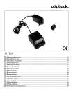
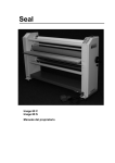
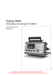
Technical Documentation Oxylog 2000 plus Emergency and Transport Ventilator WARNING! The proper servicing and testing of this device requires a full understanding of this Technical Documentation. Carefully read this Technical Documentation and any applicable Instructions for Use prior to any use of the device. Revision 1.0 5503.320 9036363 This page has been intentionally left blank. Contents Abbreviations 1 Explanation 6 General 1 Symbols and Definitions 8 2 Notes 8 Function Description 1 General 10 2 Functional principle 10 3 Pneumatic assembly 11 3.1 Inlet ....................................................................................................................................... 11 3.2 Restrictor .............................................................................................................................. 11 3.3 Sensors and safety functions ............................................................................................... 11 3.4 PEEP valve .......................................................................................................................... 12 3.5 Ambient pressure conditions ................................................................................................ 13 4 Electronics 13 4.1 Charging Circuit PCB ........................................................................................................... 13 4.2 Sensor PCB .......................................................................................................................... 14 4.3 Front membrane cover ......................................................................................................... 14 4.4 Control PCB ......................................................................................................................... 14 Maintenance Procedures 1 Replacing the replaceable battery 16 2 Replacing the filter element 17 Schematics and Diagrams 1 General 20 Annex Parts Catalog Copyright reserved. K5503320IECIVZ.fm 11.03.08 Test instructions 3 Contents 4 K5503320IECIVZ.fm 11.03.08 Copyright reserved. This page has been intentionally left blank. Abbreviations This chapter contains a list of the abbreviations used in this manual. 5 Abbreviations Explanation Abbreviation Explanation English acronym for “Body Temperature, Pressure, Saturated” (current conditions in the patient's lung, i.e. body temperature 37 °C, ambient pressure, water-vapor saturated gas). DC English acronym for “Direct Current”. EEPROM English acronym for “Electrically Erasable Programmable Read-Only Memory”. EL display Electroluminescence display. EPROM English acronym for “Erasable Programmable ReadOnly Memory”. LED English acronym for “Light Emitting Diode”. MV English acronym for “Minute Volume”. PC English acronym for “Personal Computer”. PEEP English acronym for “Positive End Expiratory Pressure”. RAM English acronym for “Random Access Memory”. VC-CMV English acronym for the ventilation mode “Volume Control - Controlled Mandatory Ventilation”. VC-SIMV English acronym for the ventilation mode “Volume Control - Synchronized Intermittent Mandatory Ventilation”. VT English acronym for “Tidal Volume”. Copyright reserved. BTPS 6 5503.320 Revision 1.0_Printed on_11.03.08_Abkuerzungen_P.fm 1 Oxylog 2000 plus General This chapter contains general notes and definitions that are important for the use of this manual. 7 General 1 Symbols and Definitions Oxylog 2000 plus WARNING A WARNING statement provides important information about a potentially hazardous situation which, if not avoided, could result in death or serious injury. CAUTION A CAUTION statement provides important information about a potentially hazardous situation which, if not avoided, may result in minor or moderate injury to the user or patient or in damage to the equipment or other property. NOTE A NOTE provides additional information intended to avoid inconvenience during operation or servicing of the equipment. Definitions: 2 Notes Inspection = examination of actual condition Maintenance = measures to maintain specified condition Repair = measures to restore specified condition Servicing = inspection, maintenance, and repair This Technical Documentation conforms to the IEC 60601-1 standard. Read each step in every procedure thoroughly before beginning any test. Always use the proper tools and specified test equipment. CAUTION If you deviate from the instructions and/or recommendations in this Technical Documentation, the equipment may operate improperly or unsafely, or the equipment could be damaged. CAUTION Dräger recommends that only Dräger supplied repair parts be used for maintenance. Otherwise the correct functioning of the device may be compromised. NOTE Unless otherwise stated, reference is made to laws, regulations or standards (as amended) applicable in the Federal Republic of Germany for equipment used or serviced in Germany. Users or technicians in all other countries must verify compliance with local laws or applicable international standards. NOTE If the test values are not met, please contact your local service organization. 8 5503.320 Copyright reserved. This Technical Documentation is for informational purposes only. Product information contained in this Technical Documentation does not supersede Product information provided in the Instructions for Use enclosed with the product at the time of delivery. 6.0_Printed on_05.03.08_General_Technical_Documentation.fm The maintenance procedures described in this Technical Documentation may be performed by properly trained service personnel only. These maintenance procedures do not replace inspections and servicing by the manufacturer. Function Description This chapter contains descriptions of the device's technical functions. 9 Function description Oxylog 2000 plus 1 General The Oxylog 2000 plus is a time-cycled, volume controlled emergency and transport ventilator with pressure support for patients requiring mandatory or assisted ventilation with a tidal volume from 100 mL upwards. For use by and under supervision of trained health care professionals. 2 Functional principle Oxylog 2000 plus primarily comprises the pneumatic components with the connection and metering block and the control and display electronics (Fig. 1). The connection block supplies a constant pressure to the metering block, contains the safety functions such as the emergency air and safety valves, control the pressure (PEEP) during expiration and, together with the ventilation accessories, provides the interface to the patient. The metering block passes defined volumes of gas of approx. 40% or 100% oxygen to the connection block. 10 Functional principle 5503.320 Revision 1.0_Printed on_11.03.08_F5503403T01_Funktion.fm Fig. 1 Copyright reserved. The control and display electronics evaluate the measurement signals, control the valves and provide the interface to the operator. Oxylog 2000 plus Function description 3 Pneumatic assembly The following description relates to the pneumatics diagram of the Oxylog 2000 plus. The Control PCB evaluates the measurement signals of the sensors and actuates the valves. 3.1 Inlet The compressed oxygen passes through the filter F1 and the pressure regulator DR to the valves V1 to V3. The pressure regulator regulates the pressure to 3 bar. This is done to attain a stable flow control. The Control PCB monitors this pressure, which is measured with sensor S3. 3.2 Restrictor Valves V1 to V3 are proportional valves, each delivering a flow proportional to the overall flow of 0 to 35 L/min. The flow sensor S1 measures the delivered flow and the Control PCB corrects the valve operation as necessary. Valve V3 comprises two parallel configured valves, to produce a total flow greater than 100 L/min. With the valve V1 and the ejector E1 ambient air can additionally be drawn in. Valve V1 meters a flow through the ejector. The resultant negative pressure draws ambient air through the filter F2, the flow sensor S2 and the non-return valve V9. Valve V2 adds oxygen to the ambient air depending on the selected O2 concentration (40 or 100%). The proportion of ambient air may be a maximum of 75%. The minimum oxygen concentration may thus be 40%. At flows less than 9 L/min the volume of intake air is so low that an oxygen concentration of 40% is no longer guaranteed. At flows greater than 35 L/min oxygen is added accordingly. An oxygen concentration of 40% is no longer guaranteed. In a flow range from 9 to 35 L/min an oxygen concentration of 40% or 100% can be set. The non-return valve V9 prevents oxygen escaping into the ambient air. L1 prevents swirling, and ensures a uniform oxygen concentration. 3.3 Sensors and safety functions The flow sensor S1 measures the inspiratory flow inside the unit and the Control PCB corrects the operation of valves V1 to V3 as necessary based on the measured value. The emergency breathing valve NV allows the patient to breathe spontaneously in case the unit fails. The pressure sensor S4 measures the internal patient pressure inside the unit and the PEEP pressure at the ventilation valve V10. The pressure sensor S6 measures the differential pressure above the flow sensor S8 located close to the patient (Fig. 2). From it, the Control PCB calculates the flow. Copyright reserved. Revision 1.0_Printed on_11.03.08_F5503403T01_Funktion.fm The safety valve SV opens at a pressure greater than 80 mbar, to prevent the patient from being exposed to high pressure in the event of unit malfunctions. 5503.320 11 Function description Oxylog 2000 plus Fig. 2 Functional principle of the external flow sensor Pressure sensor S5 measures the pressure at the patient. Based on this pressure value, the Control PCB makes calculations including for actuation of the PEEP valve V6. Valves V7 and V8 switch the connections of S6, S5 against atmosphere at cyclic intervals. The Control PCB calibrates the sensors and any offset drift is prevented. 3.4 PEEP valve The PEEP valve V6 controls the PEEP setting of the ventilation valve V10. The Control PCB actuates a coil which delivers a pressure to a diaphragm. The internal tubing system vents to this pre-set PEEP pressure during expiration. This PEEP pressure also acts on a valve diaphragm in the ventilation valve V10 (Fig. 3/1). On expiration the pre-set PEEP pressure is established at the patient. Copyright reserved. During inspiration the PEEP valve V6 is closed by an actuation current of 130 mA. 12 5503.320 Revision 1.0_Printed on_11.03.08_F5503403T01_Funktion.fm During expiration an internal flow of 0.5 L/min flows through the PEEP valve V6 to hold the diaphragm of the PEEP valve still and ensure uniform opening of the PEEP valve. Oxylog 2000 plus Function description Fig. 3 Ventilation valve 3.5 Ambient pressure conditions Oxylog 2000 plus meters the tidal volume under BTPS conditions. Sensors S7 and S9 measure the ambient pressure. S5 measures the current pressure level in the lung. In this way the Control PCB can balance fluctuating ambient pressure and the BTPS conditions (Body Temperature, Pressure, Saturated. Measurements referred to conditions of the patient's lung, body temperature 37 °C, ambient pressure, water vapor saturated gas). 4 Electronics The following description relates to the Electronics block diagram and represents only the principle of operation. The connections of the individual modules are only indicated indirectly, and are made by cable harnesses, connectors and the conductors on the individual PCBs. 4.1 Charging Circuit PCB The Charging Circuit PCB controls charging of the internal replaceable battery and selection of the voltage supply (mains, on-board system or internal battery). The Charging Circuit PCB accommodates the input for the external voltage supply. The input is isolated from the remaining electronics by a protective circuit. The Charging Circuit PCB has its own processor system, and thus its own software. This software is also located on the Control PCB, and is loaded from there onto the Charging Circuit PCB. The internal replaceable battery has various dummy resistors, depending on the type used. The Charging Circuit PCB detects on the basis of the resistor which type is fitted (nickel metal hydride or lithium ion). The temperature and charge capacity of the internal replaceable battery is determined by the battery itself. These data are transmitted from the Charging Circuit PCB to the Control PCB. Copyright reserved. Revision 1.0_Printed on_11.03.08_F5503403T01_Funktion.fm The Charging Circuit PCB directly activates the power indicator LEDs. The LEDs are located on the front membrane cover. 5503.320 13 Function description Oxylog 2000 plus 4.2 Sensor PCB The Sensor PCB holds all the pressure sensors of the pneumatic system and the internal temperature gauge. The Sensor PCB is the interface for pressure measurement and valve actuation between the pneumatic and electronic systems. 4.3 Front membrane cover On the front membrane cover are the keys, the LEDs and the rotary knob. Together with the display, the rotary knob and the potentiometers, the front membrane cover is the interface between the unit and the operator. The display is an EL display. EL stands for electroluminescent. 4.4 Control PCB The Control PCB holds the electronic ON/OFF switch components, the voltage generation of the individual internal operating voltages, and the microprocessor system for control and monitoring of ventilation. The electronic ON/OFF circuit is directly controlled (switched on or off) by the ON/OFF switch on the device. If the device is ON and the power fails, an alarm generator generates an audible alarm signal. A Goldcap capacitor delivers the voltage for the signal. The voltage generator generates the various operating voltages from the supply voltage. For example the +5 V for the microprocessor. The microprocessor system comprises the microcontroller, an EEPROM, a flash EPROM, a RAM, and a real-time clock (RTC). The EEPROM holds the calibration data, software options, ID number, unit and service operating hours and the start-up conditions. The flash EPROM holds the medical device software and the software for the Charging Circuit PCB. The real-time clock generates the time and date. The real-time clock's RAM also holds the logs. The microprocessor system evaluates the measurement signals from the sensors, the settings of the potentiometers and the rotary knob and operates the valves and the display accordingly. 14 5503.320 Revision 1.0_Printed on_11.03.08_F5503403T01_Funktion.fm Copyright reserved. On a change of software the unit no longer needs to be opened. The infrared interface transfers the data from the PC/laptop to the microcontroller and vice versa. Maintenance Procedures This chapter describes the measures required to maintain the specified condition of the device. 15 Maintenance procedures 1 Replacing the replaceable battery Oxylog 2000 plus 1. Slacken the screw Fig. 1/1 of the battery compartment cover anti-clockwise until the cover can be opened. 2. Fold the cover Fig. 1/2 down. 3. Pull the replaceable battery Fig. 1/3 forward by its tab and withdraw it. Fig. 1 Removing the replaceable battery 4. Press the button on the new replaceable battery and check the charge. The LEDs on the replaceable battery indicate the charge condition in percent. 5. Charge the replaceable battery as necessary. NOTE The replaceable battery can be charged by the battery charger station or by the external power supply in the Oxylog 2000 plus. 6. Fit the replaceable battery. 16 5503.320 Revision 1.0_Printed on_11.03.08_W5503403T06_Wechselakku.fm Copyright reserved. 7. Switch on the Oxylog 2000 plus and check the battery capacity indicated on the display. Oxylog 2000 plus 2 Replacing the filter element Maintenance procedures 1. Switch off the device. 2. Remove screws Fig. 2. Fig. 2 Removing the filter element NOTE Note fitting position of filter element. 3. Remove the filter element. 4. Install the new filter element. 5. Carry out a unit test. Copyright reserved. Revision 1.0_Printed on_05.03.08_W5503403T03_Filtereinsatz.fm 6. Place the fully functional unit at the user's/owner's disposal. 5503.320 17 Maintenance procedures Oxylog 2000 plus 18 5503.320 Revision 1.0_Printed on_05.03.08_W5503403T03_Filtereinsatz.fm Copyright reserved. This page has been intentionally left blank. Schematics and Diagrams This chapter contains schematics and diagrams that can be of help when servicing the device. 19 Schematics and diagrams 1 General Oxylog 2000 plus This section presents the diagrams and overviews of the Oxylog 2000 plus, such as the pneumatic components diagram and the block diagram of the electronics. These schematics and diagrams are partly used as reference to the function description. Fig. 1 Overview; for legend see Table 1 Table 1 Legend Fig. 1 1 Front panel with potentiometers, rotary knob, membrane keypad, and insert strip 2 Signal generator 3 Loudspeaker 4 Display 5 Control PCB (see also Fig. 6) 6 Cover plate for pneumatic assembly 7 Pneumatic assembly and Sensor PCB (see also Fig. 3) 8 Handle 9 Filter element to filter the ambient air intake 10 Charging Circuit PCB 11 Rear panel 12 Battery compartment cover 13 Replaceable battery 20 5503.320 Revision 1.0_Printed on_11.03.08_S5503403D01_Uebersichten.fm Designation Copyright reserved. Item Oxylog 2000 plus Item Schematics and diagrams Designation 14 DC voltage socket 15 Sockets for flowmeter tubes, ventilation tube and compressed gas tube 16 Base plate Fig. 2 Pneumatic components diagram, for legend, see Table 2 Table 2 Legend Fig. 2 and Fig. 3 Item Designation 1 Connection block 2 Metering block Copyright reserved. Revision 1.0_Printed on_11.03.08_S5503403D01_Uebersichten.fm DR Pressure regulator (PR) E1 Ejector F1 Filter in O2 compressed gas connection port F2 Filter for intake air L1 L1 makes sure there is an even flow NV Emergency-air valve S1 Flow sensor to measure internal inspiratory flow S2 Flow sensor to measure the ambient air intake S3 Pressure sensor (Pv) to measure supply pressure for valves V1 to V3 S4 Pressure sensor (Pint) to measure unit-internal patient pressure 5503.320 21 Schematics and diagrams S5 Pressure sensor (Paw) to measure pressure close to patient S6 Pressure sensor (delta P) to measure differential pressure at external flow sensor S7 and S9 Pressure sensors to measure ambient pressure S8 External flow sensor SV Safety valve V1 to V3 Metering valves V10 Ventilation valve V6 PEEP valve V7 and V8 Switching valves to calibrate pressure sensors S5 and S6 V9 Non-return valve Fig. 3 22 Overview of pneumatic components, for legend see Table 2 5503.320 Revision 1.0_Printed on_11.03.08_S5503403D01_Uebersichten.fm Designation Copyright reserved. Item Oxylog 2000 plus Oxylog 2000 plus Fig. 4 Tubing diagram, for legend, see Table 3 Table 3 Legend Fig. 4 Designation 1 Sensor PCB 2 Connection block 3 Metering block 4 Tube 4x1 PAE not colored (nc) 5 Tube 2x1.5 Si not colored (nc) 6 Tube 2x1 Si blue (bu), red (rd), orange (og) Copyright reserved. Revision 1.0_Printed on_11.03.08_S5503403D01_Uebersichten.fm Item Schematics and diagrams 5503.320 23 Electronics block diagram Fig. 6 Control PCB, for legend, see Table 4 24 5503.320 Revision 1.0_Printed on_11.03.08_S5503403D01_Uebersichten.fm Fig. 5 Oxylog 2000 plus Copyright reserved. Schematics and diagrams Oxylog 2000 plus Table 4 Schematics and diagrams Legend Fig. 6 Item Designation 1 EEPROM 2 Goldcap capacitor 3 Microcontroller 4 Real-time clock with battery A Control PCB mounting screws X120 Connection to signal generator X200 Connection to Sensor PCB X220 Connection to potentiometers X270 Connection to loudspeaker X312 Jumper to trigger a reset X400 Connection to flow sensor S1 X440 Connection to flow sensor S2 X609 Jumper to perform bootstrap download X665 Connection to rotary encoder X700 Connection to Charging Circuit PCB X730 Connection to front membrane (keys). X740 Connection to front membrane (LEDs) X760 Connection to display Copyright reserved. Revision 1.0_Printed on_11.03.08_S5503403D01_Uebersichten.fm X790 Pin strip for bootstrap download 5503.320 25 Schematics and diagrams Oxylog 2000 plus 26 5503.320 Revision 1.0_Printed on_11.03.08_S5503403D01_Uebersichten.fm Copyright reserved. This page has been intentionally left blank. Annex Parts Catalog This chapter contains a list of the device's orderable parts. Test instructions This chapter contains the measures required to determine the actual condition of the device. This page has been intentionally left blank. Parts catalog Oxylog 2000 plus Revision: 00 2008-04-28 5503.320 Parts catalog Product concerned Description Qty. Qty.unit Remark Copyright reserved. Item Order No. No. Items that are shown in the illustration but are not listed below the illustration are not available as spare parts Revision: 00 Oxylog 2000 plus Parts catalog Set, 2-yearly Item Order No. No. 1 2M86341 2M86733 Qty. Qty.unit Filter Mat 1.000 St Battery Lithium-Ionen 1.000 St Remark Copyright reserved. 2 Description Items that are shown in the illustration but are not listed below the illustration are not available as spare parts Oxylog 2000 plus Revision: 00 Parts catalog Accessories/Consumables Copyright reserved. Item Order No. No. 1824481 Description Qty. Qty.unit Power Cable CE,3m,10A,C13L,bk 1.000 St 1868160 Cable TH/BR,3m,C13,black RoHS 1.000 St 1844342 Power cable DK, 3 m, 10 A 1.000 St 1844369 Power cable Great Britian 3m black 1.000 St 1844377 POWERCORD CH 3M 1.000 St 1851705 Cable Australia,3m,10A,C13 1.000 St 1859706 Power cable 10A,3m,black,China 1.000 St 2M86729 Battery Charger 1.000 St 2M86730 AC/DC power pack 1.000 St 2M86731 DC/DC Converter 1.000 St 2M86733 Battery Lithium-Ionen 1.000 St ME05133 Conversion kit reusable 1.000 St ME05134 Conversion Kit Disposable 1.000 St 5703307 Carrying Belt 1.000 St 5704216 All-round Wall Holder 1.000 St 5704217 Quick Power Connector 1.000 St 5704218 Wall Holder Adaptation Plate 1.000 St 5704641 All round Wall Holder USA 1.000 St 2M86900 Equipment holder 1.000 St 5704640 Equipment Holder USA 1.000 St Remark Items that are shown in the illustration but are not listed below the illustration are not available as spare parts Oxylog 2000 plus Revision: 00 Parts catalog Accessories/Consumables Item Order No. No. Qty. Qty.unit 5704441 Hose O2 DISS-DISS gr 1,5m 1.000 St 5704447 Hose O2 DISS-DISS gr 3 m 1.000 St 5704440 Hose O2 DISS-DISS gr 1,5m spr 1.000 St 5704442 Hose O2 DISS-DISS gr 3 m spr 1.000 St 2M86975 Carrying System 1.000 St CP-Catalog Accesso./Consumabl. 1.000 St Remark Copyright reserved. Description Items that are shown in the illustration but are not listed below the illustration are not available as spare parts Revision: 00 Oxylog 2000 plus Parts catalog Carrying System Item Order No. No. Copyright reserved. 2 8412716 Description Qty. Qty.unit O2-Connector Tube 0,5m 1.000 St Remark Items that are shown in the illustration but are not listed below the illustration are not available as spare parts Oxylog 2000 plus Revision: 00 Parts catalog Carrying System Description Qty. Qty.unit 5 5704500 Gas Supply System 1.000 St 6 5704216 All-round Wall Holder 1.000 St Remark Items that are shown in the illustration but are not listed below the illustration are not available as spare parts Revision: 00 Oxylog 2000 plus Copyright reserved. Item Order No. No. This page has been intentionally left blank. Test instructions (TL) Oxylog 2000 plus NOTE The procedures described in this Test List can be carried out using commercially available test equipment and tools; however, this Test List does not replace inspections and maintenance by the manufacturer. General: Copyright reserved. Revision 1.0_Printed on_11.03.08_EN_IMAP_TL_P_Front.fm All results must be documented in the Test Report. - Oxylog 2000 plus Revision 1.0 1 of 20 2 of 20 - Oxylog 2000 plus Revision 1.0 Revision 1.0_Printed on_11.03.08_EN_IMAP_TL_P_Front.fm Copyright reserved. This page has been intentionally left blank. 1 Device configuration 1.1 Oxylog 2000 plus device configuration . . . . . . . . . . . . . . . . . . . . . . . . . . . . . . . . . . . . . . . . . . . . . . . . . . . . . .6 1.1.1 Serial number of the Oxylog (if not otherwise recorded) .....................................................................6 1.1.2 Serial number of the power supply unit (if not otherwise recorded) ....................................................6 1.1.3 Software version ..................................................................................................................................6 2 Electrical safety 2.1 Electrical safety according to VDE 0751/IEC 60601-1 . . . . . . . . . . . . . . . . . . . . . . . . . . . . . . . . . . . . . . . . . . .8 2.1.1 Oxylog 2000 plus - not applicable - .....................................................................................................8 2.1.2 Power supply unit visual check ............................................................................................................8 2.1.3 Protective earth conductor of power supply cord ................................................................................8 3 Function and condition test 3.1 Condition test . . . . . . . . . . . . . . . . . . . . . . . . . . . . . . . . . . . . . . . . . . . . . . . . . . . . . . . . . . . . . . . . . . . . . . . . .10 3.1.1 Labels and Instructions for Use .........................................................................................................10 3.1.2 Basic unit, outside .............................................................................................................................10 3.1.3 Carrier system and accessories ........................................................................................................10 3.2 Basic unit function . . . . . . . . . . . . . . . . . . . . . . . . . . . . . . . . . . . . . . . . . . . . . . . . . . . . . . . . . . . . . . . . . . . . .11 3.2.1 Unit test .............................................................................................................................................11 3.2.2 Buttons and potentiometer ................................................................................................................11 3.2.3 Loudspeaker, buzzer, LEDs and display ...........................................................................................11 3.2.4 Voltage supply ...................................................................................................................................11 3.2.5 Supply pressure/emergency air valve ...............................................................................................12 3.2.6 Safety valve .......................................................................................................................................13 3.3 Ventilation . . . . . . . . . . . . . . . . . . . . . . . . . . . . . . . . . . . . . . . . . . . . . . . . . . . . . . . . . . . . . . . . . . . . . . . . . . .14 3.3.1 Volume-controlled ventilation ............................................................................................................14 3.3.2 Trigger function ..................................................................................................................................14 3.4 Device handover . . . . . . . . . . . . . . . . . . . . . . . . . . . . . . . . . . . . . . . . . . . . . . . . . . . . . . . . . . . . . . . . . . . . . .16 4 Test equipment 4.1 Test equipment list . . . . . . . . . . . . . . . . . . . . . . . . . . . . . . . . . . . . . . . . . . . . . . . . . . . . . . . . . . . . . . . . . . . . .18 5 Annex 5.1 Accessing service mode . . . . . . . . . . . . . . . . . . . . . . . . . . . . . . . . . . . . . . . . . . . . . . . . . . . . . . . . . . . . . . . .20 5.1.1 Accessing the Customer Service Mode .............................................................................................20 Copyright reserved. P5503320_TLIVZ.fm 11.03.08 Contents 3 of 20 Contents 4 of 20 P5503320_TLIVZ.fm 11.03.08 Copyright reserved. This page has been intentionally left blank. 1 Device configuration 5 of 20 Test instructions (TL) Oxylog 2000 plus device configuration 1.1 Oxylog 2000 plus device configuration 1.1.1 Serial number of the Oxylog (if not otherwise recorded) Action Entry • Read the serial number on the Oxylog 2000 plus (the serial number is located on the name plate). Oxylog 2000 plus serial number [________txt] 1.1.2 Serial number of the power supply unit (if not otherwise recorded) Action Entry • Read the serial number on the power supply unit. Serial number of the power supply unit [________txt] 1.1.3 Software version Action Entry • Read out and enter the software version later under „Function and condition test“ (the software version is displayed immediately after power-on). Software version Oxylog 2000 plus 6 of 20 - Oxylog 2000 plus Revision 1.0 Revision 1.0_Printed on_11.03.08_P5503320_Configuration.fm Copyright reserved. [________txt] 2 Electrical safety 7 of 20 Test instructions (TL) Electrical safety according to VDE 0751/IEC 60601-1 2.1 Electrical safety according to VDE 0751/IEC 60601-1 2.1.1 Oxylog 2000 plus - not applicable 2.1.2 Power supply unit visual check Test Result The power supply unit, the power supply cord, and the connecting cable to the Oxylog are neither damaged nor contaminated. Condition checked. [________OK] 2.1.3 Protective earth conductor of power supply cord NOTE The power supply unit (2M86730) conforms to the requirements of protection class 2. Test Result The value of the protective earth conductor resistance must not exceed 0.1 ohms. Protective earth conductor resistance 8 of 20 - Oxylog 2000 plus Revision 1.0 Revision 1.0_Printed on_11.03.08_P5503320_VDE_IEC_Schutzleiter_TL.fm Copyright reserved. [________Ohm] 3 Function and condition test 9 of 20 Test instructions (TL) Condition test 3.1 Condition test Prerequisites The device is fully assembled. 3.1.1 Labels and Instructions for Use Test – Labels and markings are complete and legible. – The Instructions for Use are available (according to user/owner). – Only applicable in Germany: The medical product log is available (according to user/owner). Result Condition checked. [________OK] 3.1.2 Basic unit, outside Test – The housing, connections, front membrane, control elements, and handle are neither contaminated nor damaged. – The ventilation tube and ventilation valve are not hardened or damaged. Result Condition checked. [________OK] 3.1.3 Carrier system and accessories Test – The carrier system and accessories are not damaged. – The connecting cables are not porous, severely kinked or damaged. – Check that the wall mount (if present) is attached securely. Action Test Result • Latch the Oxylog onto the wall mount (if present). – The „external mains power“ LED lights up. Condition and function checked. 10 of 20 - Oxylog 2000 plus Revision 1.0 Revision 1.0_Printed on_11.03.08_P5503320_Function_condition.fm Copyright reserved. [________OK] Test instructions (TL) Basic unit function 3.2 Basic unit function 3.2.1 Unit test Action • Connect the unit to the electrical power and to the O2 compressed gas supply. • Connect the ventilation tube and the ventilation valve to the flow sensor and the flowmeter tubes. • Connect the test lung (test thorax). • Switch on the unit and press and hold down the rotary knob until the menu for selection of the unit test appears. • Select and activate the unit test. • Follow the on-screen instructions. Test Result The unit test runs without error. Function checked. [________OK] 3.2.2 Buttons and potentiometer Action • Switch the unit to Customer Service Mode. • Activate „Test buttons and potentiometer” test step. • Press all buttons on the unit one after the other. Test Action Test Result When a button is pressed a corresponding „X“ appears on-screen. If the button has an integral LED, the LED lights up while the button is being pressed. If there is no LED, the yellow warning LED is lit. • Turn the potentiometer to various settings and compare them against the values displayed on-screen. The pre-set and displayed values are identical. Function checked. [________OK] Action • Activate „Test loudspeaker, buzzer, LEDs and display” test step. • Run the complete test. Test Result The tests of the loudspeaker, the buzzer, the LEDs and the display were successful. Function checked. [________OK] 3.2.4 Voltage supply Copyright reserved. Revision 1.0_Printed on_11.03.08_P5503320_Function_device_check_TL.fm 3.2.3 Loudspeaker, buzzer, LEDs and display Action • Switch off the device. • Connect the ventilation tube instead of the manometer. Test The „external mains power“ LED lights up green. - Oxylog 2000 plus Revision 1.0 11 of 20 Test instructions (TL) Basic unit function The “charge” indicator LED of the internal replaceable battery lights up in the following colors: – yellow: when the replaceable battery is charging – green: when the replaceable battery is fully charged, – red: when no functional replaceable battery is inserted or the replaceable battery cannot be charged, such as because the unit is being used outside the temperature range of 0 to 35 °C. Action • Switch on the device. • Set ventilation mode VC-CMV. • Remove internal replaceable battery. Test Action Test Action Test Action Test Action Test Action Test Action The unit continues ventilating. The display shows the message „No battery“. The charge indicator LED is lit red. An audible alarm sounds. • Fit the internal replaceable battery. The charge indicator LED is lit green. The audible alarm is deactivated. • Press the „Alarm Reset“ button. The „No battery“ message is no longer displayed. • Remove external power supply. The unit continues ventilating. The „external mains power “ LED is off. The „charge status“ LED of the internal replaceable battery is off. An audible alarm sounds. The display shows the message „Battery operating“. • Press the „Alarm Reset“ button. The „Battery operating“ message is no longer displayed. • Remove internal replaceable battery. Ventilation stops. An acoustic alarm sounds for at least 7 seconds. • Fit the internal replaceable battery. • Connect the external power supply. Test Result Ventilation is resumed with the previous settings. Function checked. 3.2.5 Supply pressure/emergency air valve Action Test • Remove compressed gas supply. – An audible alarm sounds. – The display shows the message „!!Supply pressure low“. – The yellow alarm LED comes on. Action • Simulate spontaneous breathing with the test thorax. Test Ventilation through the emergency air valve is possible. Action Test Copyright reserved. – Ventilation stops. • Connect the compressed gas supply. – The audible alarm stops. – The yellow alarm LED is no longer lit. – Ventilation is resumed with the previous settings. 12 of 20 - Oxylog 2000 plus Revision 1.0 Revision 1.0_Printed on_11.03.08_P5503320_Function_device_check_TL.fm [________OK] Test instructions (TL) Basic unit function Action Test Result • Press the „Alarm Reset“ button. – The „!!Supply pressure low“ message is no longer displayed. Function checked. [________OK] 3.2.6 Safety valve Action • Set Pmax and PEEP to maximum. • Set the frequency to 10 1/min. • Connect a manometer instead of the ventilation tube (the connection must be tight). Test Result – The maximum pressure is 85 mbar (110 mbar for the USA unit). Function checked. [________OK] • Disconnect the manometer and reconnect the ventilation tube. Copyright reserved. Revision 1.0_Printed on_11.03.08_P5503320_Function_device_check_TL.fm Action - Oxylog 2000 plus Revision 1.0 13 of 20 Test instructions (TL) Ventilation 3.3 Ventilation Prerequisites – Unit is connected to electrical power and to O2 compressed gas supply. – Ventilation tube, ventilation valve with flow sensor and flowmeter tubes are connected. – Test lung (breathing bag and catheter connector) is connected to flow sensor with elbow adapter. – Unit is switched on. 3.3.1 Volume-controlled ventilation Action • Make the following settings: – Ventilation mode = VC-CMV – Frequency = 10 1/min – Alarm limit Pmax = 60 mbar (Oxylog 100 cmH2O - USA = 100 mbar) – PEEP = 5 mbar – FiO2 = O2Airmix – I/E = 1:1 – Tplat = 50% – Trigger = off – VT = see table • Using the „Values 1“ button, select the VT or MV measured value, as applicable, and set and check the following values: Test Result VT MV 200 mL 1.3 L/min to 2.3 L/min 500 mL 3.7 L/min to 5.3 L/min 1000 mL 8 L/min to 10.3 L/min Measured values checked. [________OK] Action • Connect the test thorax instead of the test lung. • Change or set, as applicable, the following values: – Ventilation mode = VC-SIMV – Frequency = 5 1/min – PEEP = 10 mbar – VT = 500 mL – Ti = 1 second – Flow trigger = 3 L/min Test Copyright reserved. – Flow ramp = not applicable, or standard The test thorax inflates to a PEEP pressure of 10 mbar. No self-triggering occurs. Action 14 of 20 • Trigger using the test thorax, see the following figure. - Oxylog 2000 plus Revision 1.0 Revision 1.0_Printed on_11.03.08_P5503320_Function_breathing_check.fm 3.3.2 Trigger function Test instructions (TL) Ventilation Fig. 1 Trigger Item Designation Test 1 Unsynchronized mandatory breath 2 Synchronized mandatory breath 3 Trigger window The unit triggers and activates a mandatory breath. At the same moment a „star“ appears on the top line of the display. Result Function checked. Copyright reserved. Revision 1.0_Printed on_11.03.08_P5503320_Function_breathing_check.fm [________OK] - Oxylog 2000 plus Revision 1.0 15 of 20 Test instructions (TL) Device handover 3.4 Device handover Entry Place fully functional device at the user's/owner's disposal. 16 of 20 - Oxylog 2000 plus Revision 1.0 Revision 1.0_Printed on_11.03.08_P5503320_Function_Product.fm Copyright reserved. [________OK] 4 Test equipment 17 of 20 Test instructions (TL) Test equipment list 4.1 Test equipment list Test equipment Digital manometer up to 1000 mbar Test lung (test thorax) Breathing bag, 2-liter Catheter connector 7 mm 18 of 20 - Oxylog 2000 plus Revision 1.0 Revision 1.0_Printed on_11.03.08_P5503320_test_tools_TL.fm Copyright reserved. Tester for electrical safety test 5 Annex 19 of 20 Test instructions (TL) Accessing service mode 5.1 Accessing service mode 5.1.1 Accessing the Customer Service Mode Action • Turn the controls Fig. 2/1 fully clockwise. • Switch on the unit by the key Fig. 2/3 and at the same time press and hold down the keys Fig. 2/2 until Customer Service Mode appears. Fig. 2 Accessing the Customer Service Mode 20 of 20 - Oxylog 2000 plus Revision 1.0 Revision 1.0_Printed on_11.03.08_P5503320_Annex_SM_TL.fm Copyright reserved. • Now the appropriate test can be selected and activated. To quit service mode switch off the unit. The values set in Customer Service Mode are retained and reactivated every time ventilation is started following powerup. Test Report (TL) Institution: Delivery date: Serial no.: Other: OK Para Name Result OK 1 Device configuration Para Name 1. 1 Oxylog 2000 plus device configuration 3. 2 Basic unit function 1. 1. 1 Serial number of the Oxylog (if not otherwise recorded) 3. 2. 1 Unit test 1. 1. 2 Serial number of the power supply unit (if not other 3. 2. 2 Buttons and potentiometer 1. 1. 3 Software version 3. 2. 3 Loudspeaker, buzzer, LEDs and display 2 Electrical safety 3. 2. 4 Voltage supply 2. 1 Electrical safety according to VDE 0751/IEC 60601-1 3. 2. 5 Supply pressure/emergency air valve 2. 1. 2 Power supply unit visual check 3. 2. 6 Safety valve 2. 1. 3 Protective earth conductor of power supply cord Ohm Result 3. 1. 3 Carrier system and accessories 3. 3 Ventilation 3 Function and condition test 3. 3. 1 Volume-controlled ventilation 3. 1 Condition test 3. 3. 2 Trigger function 3. 1. 1 Labels and Instructions for Use 3. 4 Device handover 3. 1. 2 Basic unit, outside Report: Test has been performed according to the test instructions (TL). Name: ________________________ Date/signature: ________________________ Revision 1.0 Oxylog 2000 plus 1/1 Manufacturer: Distributed in the USA by: Dräger Medical b.v. Draeger Medical, Inc. Kanaaldijk 29 3135 Quarry Road 5683 CR BEST Telford, PA 18969 The Netherlands USA Phone: (+31) 499 331 - 331 Phone: (215) 721-5400 Fax: (+31) 499 331 - 335 Web: http://www.draeger.com (800) 4DRAGER (800 437-2437) Fax: (215) 723-5935 Subject to change without notice. Will not be replaced in the event of modifications. © Copyright March 2008 by Dräger Medical AG & Co. KG, Lübeck, Germany.