1
Chery QQ Service Manual
Mechanical Part of SQR 472Engine
SQR 472 Engine
(Service Manual for Mechanical Part)
After-sales Department of Chery Automobile Sales Co., Ltd.
1
Chery QQ Service Manual
Mechanical Part of SQR 472Engine
CONTENTS
Chapter 1 Reading Instruction ......................................................................................................................................2
1) Reading method of Maintenance Instruction............................................................................................................2
2) Meaning of Marks and Abbreviations ......................................................................................................................3
3) Special Maintenance Tool.........................................................................................................................................4
Chapter 2 Disassembly, Assembly and Maintenance....................................................................................................6
1) Timing Belt...............................................................................................................................................................6
1. Structure Diagram.............................................................................................................................................6
2. Disassembly ......................................................................................................................................................7
3. Installation ......................................................................................................................................................10
2) Camshaft.................................................................................................................................................................13
1. Structure Diagram...........................................................................................................................................13
2. Disassembly ....................................................................................................................................................14
3. Installation ......................................................................................................................................................16
4. Routine Inspection of Valve ............................................................................................................................19
3) Cylinder Head.........................................................................................................................................................22
1. Structure Diagram...........................................................................................................................................22
2. Disassembly ....................................................................................................................................................23
3. Routine Inspection ..........................................................................................................................................23
4) Water Pump ............................................................................................................................................................29
1. Structure Diagram...........................................................................................................................................29
2. Disassembly ....................................................................................................................................................29
3. Cleanup ...........................................................................................................................................................29
4. Routine Inspection ..........................................................................................................................................29
5. Assembly.........................................................................................................................................................29
5) Oil Pump.................................................................................................................................................................29
1. Structure Diagram...........................................................................................................................................30
2. Disassembly ....................................................................................................................................................30
3. Cleanup ...........................................................................................................................................................30
4. Disassembly and Assembly of Engine Oil Pump............................................................................................43
4.1 Structure Diagram.................................................................................................................................42
4.2 Disassembly ..........................................................................................................................................42
4.3 Routine Inspection ................................................................................................................................42
4.4 Installation.............................................................................................................................................44
5. Disassembly of Oil Seal..................................................................................................................................45
5.1 Structure Diagram.................................................................................................................................45
5.2 Disassembly ..........................................................................................................................................46
5.3 Inspection..............................................................................................................................................46
5.4 Assembly of Oil Seal ............................................................................................................................46
6 Assembly..........................................................................................................................................................46
6) Crank Connecting Rod Mechanism........................................................................................................................46
1. Structure Diagram...........................................................................................................................................48
2. Disassembly of Crank Connecting Rod mechanism .......................................................................................48
3. Cleanup ...........................................................................................................................................................49
4. Routine Inspection ..........................................................................................................................................52
5. Assembly of Crank Connecting Rod Mechanism ...........................................................................................53
1
Chery QQ Service Manual
Mechanical Part of SQR 472Engine
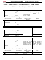
Chapter 3 Table of Main Fit Clearance for SQR472 Engine ......................................................................................55
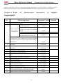
Chapter 4 Table of Measurement Parameters of SQR472 Engine ..............................................................................59
Chapter 5 Table of Main Fitting Torque for SQR472 Engine .....................................................................................61
Chapter 6 Positions on SQR472 Engine to be Lubricated ..........................................................................................62
Chapter 7 Positions on SQR472 Engine to be Spread with Sealant............................................................................65
2
Chery QQ Service Manual
Mechanical Part of SQR 472Engine
Chapter 1. Reading Instruction
1) Reading Method of Maintenance Instruction
1.1 Auxiliary Materials
If it is required in the operation instruction to prepare the auxiliary materials such as special tools, tools, measuring
instruments and grease in advance, you should list all auxiliary materials required in a table before carrying out each
operation.
Since the ordinary tools, lifter and spare parts are conventional materials used in the maintenance, they are omitted
here.
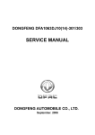
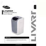
1.2 Operating Sequence and Structure Diagram
(1) The diagram of structure and components, name of components and installation status are set forth at the
beginning of each chapter or section.
(2) The number in the figure refers to the disassembly sequence of each component. The components which may not
be reused and the tightening torque are indicated in the figure.
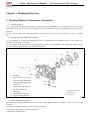
① Seal Ring
② Engine Oil Pump Cover Sheet
③ Engine Oil Pump Outer Rotor
④ Engine Oil Pump Inner Rotor
⑤ Cotter Pin
⑥ Oil Drain Valve Spring Seat
⑦ Oil Drain Valve Spring
※: Components which may
⑧ Slide Block
not be reused
⑨ Crankshaft Front Oil Seal
⑩
Unit: N·m(kg·cm)
Engine Oil Pump Housing
1 .3 Content Omitted in this Manual
The following operating procedures have been omitted in this Manual, and they should be carried out in the actual
operation:
(1) Operation relating to the lifter and the small-sized elevator;
(2) Cleaning and wipping of common components;
(3) Relevant visual inspection.
3
Chery QQ Service Manual
1 .4
Mechanical Part of SQR 472Engine
Definitions
Standard value
Refers to allowed value during inspection, maintenance and adjustment.
Limit
Refers to the maximum or minimum value that should not be exceeded during
inspection, maintenance and adjustment
Reference
Set the standard value for simple measurement to prevent from its measuring
difficulty and inconsistency to facts.
Difference
Refers to the difference between maximum value and minimum value.
It carries the cases of damaging the vehicle and parts so you should pay attention
to the operation description.
Notice
It records the operation descriptions of cases about person accident.
Warning
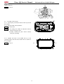
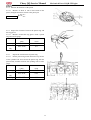
2) Meaning of Marks and Abbreviations
Mark
Original Words
Intepretation
RH
Right Hand
Right Hand
LH
Left Hand
Left Hand
FR
Front
Front
RR
Rear
Rear
IN
Intake
Intake
EX
Exhaust
Exhaust
SAE
Society of Automotive Engineers
Society of Automotive Engineers
API
American Petroleum Institute
American Petroleum Institute
SPECIAL
Special Tool
TOOL
Special Tool
T
Torque
Torque
Ay
Assembly
Assembly
S/A
Sub Assembly
Sub Assembly
W/
With
With
M/T
Manual Transmission
Manual Transmission
A/T
Automatic Transmission
Automatic Transmission
T/C
Turbo Charger
Turbo Charger
4
Chery QQ Service Manual
Mechanical Part of SQR 472Engine
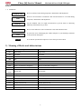
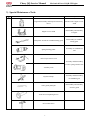
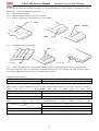
3) Special Maintenance Tools:
Outside view
Name or symbol
Purpose
Engine disassembly and inspection auxiliary
device
Mount on the engine service
stand
Engine service stand
Disassembly and assembly
of engine
Clamp hole wrench for camshaft timing gears
Disassembly of camshaft
timing gears
Spring bushing puller
Assembly of camshaft Oil
seal
Valve keeper remove tool
Assembly and disassembly
of valve spring retainer lock
Auxiliary tools
Flywheel clamp
Assembly and disassembly
of crankshaft gear
Valve guide punch pin
Disassembly and assembly
of Valve guide
Axial Oil seal replacing device
Oil seal base drive
5
Chery QQ Service Manual
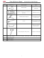
Outside view
Mechanical Part of SQR 472Engine
Name or symbol
Purpose
Piston pin puller
Disassembly and assembly
of piston pin
Embeded combination oil seal and helical
gear puller
Installation of oil seal
Crankshaft pulley holding tool
Disassembly and assembly
of crankshaft pulley
Wrench
Disassembly and assembly
of crankshaft driven gear
Replace valve clearance
adjustment gasket
Water pump pulley locking wrench
Assembly of coolant pump
Measuring
tools
Feeler gauge. Micrometer caliper. Ruler. Dial gauge. Cylinder gauge. Caliber. Pressure gauge. Torque
wrench torque wrench
Tool
Piston ring extractor
Oil
Engine Oil, adhesive
6
Chery QQ Service Manual
Mechanical Part of SQR 472Engine
Chapter 2. Disassembly, Assembly and Maintenance
Disassemble or assemble the engine with roll over stand.
Disassemble or assemble the engine parts on the roll over
stand.
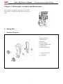
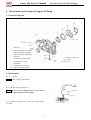
1) Timing Belt
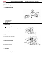
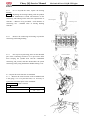
1. Structure Diagram
① Water pump pulley
② Timing shroud
③ Timing belt
④ Torsional damper
⑤ Timing belt back plate
⑥ Tension pulley
⑦ Camshaft timing pulley
※: Components which may
not be reused.
Unit: N·m(kg·cm)
7
Chery QQ Service Manual
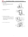
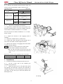
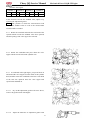
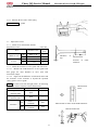
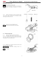
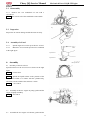
2. Disassembly
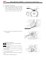
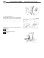
2.1 Remove the water pump pulley as the view showing.
It will be better of disassembling with special tool.
Torque: 25±1.5 N.m
2.2 Disassembly of Timing Belt Cover
Torque: 6±1N.m
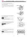
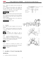
2.3 Disassembly of torsional damper
Use special tools to prevent the gear ring from
rotating. When disassembling the fixing bolts of the
torsional damper, make sure that the marks on the
crankshaft timing pulley match with the timing marks
on the engine oil pump.
2.4 Remove the timing belt back plate.
8
Mechanical Part of SQR 472Engine
Chery QQ Service Manual
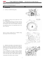
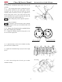
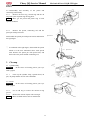
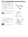
2.5 Disassembly of tension pulley
2.5.1 Compress the top dead center at the first cylinder
piston. After disassembly of timing cover, pull the
bolt and clockwise rotate the timing gear with
wrench. And then align the timing mark of camshaft
timing gear and the raised mark on camshaft cover;
Mechanical Part of SQR 472Engine
Timing Mark
Timing Mark
2.5.2 Screw off the bolt of tension pulley and remove the
tension pulley.
2.6 Disassembly of timing belt
Notice: Do not use sharp tools like screwdriver during
disassembly of belt.
Notice: Pay attention to the following items during using
the timing belt:
l Do not bend the belt with small angle, or the rigging in
belt will break.
l Do not pollute grease and water because the using
expectancy of belt is short.
l Only clockwise rotate the engine after mounting the
belt.
2.7 Disassembly of crankshaft timing gear
9
Clockwise
Chery QQ Service Manual
Mechanical Part of SQR 472Engine
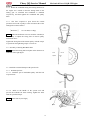
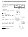
2.8 Inspect the timing belt carefully, and replace new components under any of the following circumstances or when
the mileage is up to the conditions of replacement:
2.8.1 Chap of back-side rubber
2.8.2 Chap of dedendum, chap of separated cord fabric.
2.8.3 Wearing, gear missing and incomplete gear of cord fabric.
Chap
Wearing
Chap
2.8.4
Abnormal wearing of belt flank.
Gear
Fall off with
Abnormal
2.8.5 Notice: Replace the belt as any following situation occurs, even though abrasion cannot be found directly:
The water pump leaks water out, and requires continuing infusion.If the belt is spotted with much oil stains, and the
rubber may be damaged due to expansion, you should replace the belt.
Timing belt model and type
Part number
372-1007081
Width of belt
25.3mm
Tension Pulley of Timing BeltRotate the bolt of tension pulley bracket and hear if it is noisy; check the contacting
surface and look if it is damaged.Model and type of tension pulley of timing belt
Check
if
Part number
372-1007030
Width
27.0mm
Outer diameter
φ50mm
the
out
is
damaged.Timing
belt
model
EF
Type
GL, ZL, GS, ZS
Item
Camshaft timing pulley diameter(mm)
φ110.7+0.1-0.2
Camshaft timing pulley diameter(mm)
φ54.65+0.7-0.13
10
and
type
Chery QQ Service Manual
Mechanical Part of SQR 472Engine
Check the timing belt back plate for any deformation.
Standard size of crankshaft timing gear
Width
28.6mm
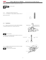
3. Installation
3.1 Assembly of crankshaft timing pulley.
Timing Mark
3.2 Installation of timing (at the top dead center of the
first cylinder piston)
3.2.1 Put the camshaft timing gear on the front end of the
exhaust camshaft, align the locating slot on the gear with
the locating pin on the end of the camshaft, and then fix
the timing gear with bolts. The tightening torque for the
bolts is 100±5Nm.
Make sure that the clashing mark of crankshaft timing
pulley aligns with the mark of oil pump.
Timing Mark
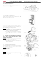
3.3 Install the tension pulley. After adjust the tension of
timing belt, install the tension pulley bolt and tighten it
with the torque specified. Adjust the tension of the timing
belt acording to the following instruction, and install the
tension pulley.
3.3.1 As indicated in the figure, make the tensioner
swing to the right with a screwdriver so that the distance
between the edge of the tension pulley and the circular arc
of the water pump body is 8mm, and then tighten the
tension pulley bolts with the torque of 25±3Nm.
11
Chery QQ Service Manual
Mechanical Part of SQR 472Engine
3.3.2 Rotate the crankshaft along the rotating direction of
the engine for 2 rounds so that the timing mark on the
timing gear of camshaft and crankshaft is matched
respectively, and then tighten the crankshaft belt pulley
bolts.
3.3.3 The force required to press down the central
position between the 2 pulleys at the in-tension side of the
timing belt for about 5mm is:
[Reference]
19.6-29.4N(2.0-3.0kg)
Notice: when the deflection can not reach the standard, it
is necessary to adjust the fixing bolt of tension pulley
mentioned above.
Tighten the fixing bolt of the tension pulley with the torque
as specified. The tightening torque is 25±3N.m
3.4 Assembly of Timing Belt Back Plate.
Notice: Install the timing belt back plate in the direction as
indicated in the right figure.
Inside
3.5 Install the torsional damper with special tools.
3.5.1 Without flywheel
3.5.1.1 Hitch the part of crankshaft pulley with the belt
of special tool.
3.5.1.2 Hold on the handle of the special tool and
prevent the toothed belt from rotating. Tighten the bolts
with the specified torque.
Torque: 98.0±10N.m{10±1kgm}
12
Outside
Chery QQ Service Manual
3.5.2
3.5.2.1
3.5.2.2
Mechanical Part of SQR 472Engine
With flywheel
Prevent the gear from rotating with special tool.
Then screw down the bolt of torsional damper.
3.6 Assembly of timing cover.
Mount the sealing strips at the positions as indicated in the
right figure. The sealing strips at the position 1 and 2
should be mounted before the assembly of the cylinder
head assembly, and the sealing strip at the position 3
should be mounted before tightening the water pump.
1
3
Install the timing cover, screw in the bolts with hand and
then tighten them.
Torque: 6±1N.m
3.7 Installation of water pump pulley.
Torque: 6±1N.m
13
2
Chery QQ Service Manual
Mechanical Part of SQR 472Engine
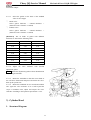
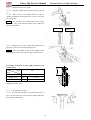
2) Camshaft
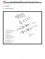
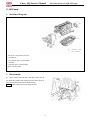
1. Structure Diagram
(1) Cylinder head chamber cover assembly
(2) Cylinder head cover gasket
(3) Camshaft timing belt
(4) Camshaft cover
※: Components which may
(5) Blanking cover
not be reused
(6) Camshaft bearing cap
Unit: N·m(kg·cm)
(7) Exhaust camshaft assembly
(8) Intake camshaft assembly
(9) Camshaft oil seal
(10) Axial spring retainer ring
(11) Saddle washer
(12) Intake camshaft sub gear
(13) Transmission ring
14
Chery QQ Service Manual
Mechanical Part of SQR 472Engine
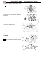
2. Disassembly
2.1 ① Cylinder head chamber cover assembly;
② Disassembly sequence of cylinder
chamber cover;
head
2.2 Remove the camshaft timing gear with special tool.
Notice: ·The special tool should be made as indicated in
the right figure.
·Use the special tool to prevent the camshaft from
rotating.
2.3 Remove the camshaft bearing cap
2.3.1 The marks on the camshaft gear should match
with each other as indicated in the right figure.
Timing Mark
15
Gear of Exhaust
Gear
of
Camshaft
Camshaft
Intake
Chery QQ Service Manual
2.3.2 Position the main sub gear on intake camshaft
with bolts, as can be seen from the right picture.
Mechanical Part of SQR 472Engine
Fixing Bolt
Notice: In order to eliminate the radial force of the
camshaft, the camshaft should be kept at the horizontal
position in the course of disassembly so as to prevent the
damage caused by the excessively high radial force.
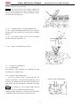
2.4 Disassemble the bolts in the order as indicated in the
right figure, and then disassembly the camshaft bearing
cap.
2.5 Remove the spark plug
2.6 Disassemble the sub gear of the camshaft.
2.6.1 If using the special tools, operate as indicated in
the right figure.
Clamp the camshaft and plug the pins of special tool into
the hole on gear; rotate the gear to keep the meshing of
driven gear and driving gear, and then remove the fixing
bolt of driven gear.
Notice: The surface of the camshaft may not be damaged.
2.6.2 If not using the special tools, operate as indicated
in the right figure.
(1) Screw M6 bolts onto the sub gear of the intake
camshaft at the position as indicated in the right figure.
(2) Use the screwdriver to turn the gear as indicated in
the figure, and disassemble the fixing bolts of the sub
gear.
Notice: The surface of the camshaft may not be damaged.
(3) Disassemble the axial elastic retainer ring with
tensioner and remove the saddle spring washer,
transmission ring, and so on.
For Fixing
Bolt
2.7 Camshaft
16
Chery QQ Service Manual
Mechanical Part of SQR 472Engine
2.7.1 Measure the camshaft with micrometer caliper. If it
is below to the specified limit, replace with a new one.
Camshaft journal
Unit: mm
Type
EF
Item
ZL, RL GL, GS, ZS
IN
φ23.0-0.02-0.033
EX
φ23.0-0.02-0.033
IN
φ22.9
EX
φ22.9
Standard value
Limit: 0.10
2.7.2
Inspection of camshaft axial clearance
(1) Replace the camshaft when the axial clearance value
measured with dial gauge exceeds the standard value.The
axial clearance of intake camshaft is 0.1~0.170mm.
The axial clearance of exhaust camshaft is 0.1~ 0.173mm.
Limit: 0.18mm.
2.7.3 Inspect the clearance of the engaging tooth of
camshaft
(1) Install the camshaft into the cylinder head.
(2) Confirm the mark forwards on the bearing cap as
well as the axle number, and then tighten the bolts.
(3) Measure the clearance of engaging tooth of the intake
camshaft with dia indicator.
Notice: ·Measure at 4 points on the circle of the piston
·Turn the intake camshaft with special tools.
·Make sure that the marks on the driven gear and
the driving gear of the camshaft match with each
other.
Inspect the clearance of the engaging tooth of camshaft:
Item
Standard value
Limit
Single tootj
0.04-0.13
0.30
3. Installation
3.1 Under the circumstance that special tools are used:
3.1.1
Fix the 2 holes (φ6) of the camshaft gear
assembly with special tool.
3.1.2
Rotate the driven gear to the right with special
tool and tally the mark hole of driven gear with that of
camshaft driving gear, or their marking way complies with
each other, fix the driven gear with bolts.(Thread: M5;
Thread pitch: 0.8)
For Fixing
17
Chery QQ Service Manual
3.2 Under the circumstance that special tools are not
available:
3.2.1
Screw the M6 bolts into the camshaft driven gear
at the position indicated in the right figure. Insert a
screwdriver into the gap between the M6 bolt and the
camshaft journal and trun the driven gear rightwards so
that the fitting mark of the 2 gears match with each other
or the tooth head of the 2 gears accord with each other, and
then fix the driven gear with bolts (M5×0.8).
Mechanical Part of SQR 472Engine
Bolt
Notice: Don’t damage the journal, adjust the operation.
3.3 Assembly of camshaft
Notice: Pay attention to the axial clearance of the camshaft
3.3.1 Spread grease on the gear of camshaft and the axial
of cylinder head.
Timing Mark
3.3.2 Remove the fixing bolts for camshaft driven
gear after mounting the camshaft.
3.3.3 Mount the camshaft, align the timing mark as can
be seen from the right picture
Gear
of
Exhaust
3.3.4 Spread oil fully on the cam of camshaft assembly,
gears and axial of cylinder head.
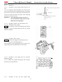
3.4 Tighten the camshaft bearing cap by the order of right
picture.
For Fixing
3.5 Screw off the fixing bolts for driven gear of intake
camshaft assembly.
18
Gear of Intake camshaft
Chery QQ Service Manual
3.6 Assembly of camshaft cove
Spread sealant on the position (slot) of camshaft cover as
can be seen from the right picture.
Mechanical Part of SQR 472Engine
Glue Spread Line
3.6.1 Assembly of Camshaft Cover
Tighten the bolts in the order as indicated in the right
figure and with the specified torque.
3.6.2 After spreading oil on the blanking aperture of
cylinder head and the mounting surface of blanking cover,
press the blanking cover with special tool.
Notice:·The blanking cover should be installed in the
direction as indicated in the right figure.
· After being pressed, the blanking cover should be
1±1mm higher than the surface of thecylinder
head.
Outside
3.7 Spread the edge of the camshaft oil seal with oil, and
press it into the cylinder head with M10 bolt (length:
50-60mm) and special tools.
Notice:· If the oil seal is reused, spread it with oil before
pressing it into the cylinder head.
· After removing the bolt, knock it with hand so as to
inspect and confirm it.
3.8 Assembly of camshaft timing gear
After spreading sealant on the bolt, prevent it from rotating
with special tool and screw down the bolt of camshaft
timing gear in specified torque.
Torque: 100±5N.m
Notice: Process the special tools as indicated in the right
figure before using them.
19
Chery QQ Service Manual
Mechanical Part of SQR 472Engine
3.9 Installation of cylinder head cover
3.9.1 The old cushion of the timing belt cover which
contacts the cylinder head cover should be removed
completely.
3.9.2 Put the new cushion into the gloove of the timing
belt cover accurately.
3.9.3 Mount the cylinder head cover on the cylinder
head, and tighten the 8 bolts in the order as indicated in the
right figure and with the specified torque.
Torque: 6±1N.m
4
Inspection of valve
4.1
Standard valve clearance:
Valve clearance
Timing
IN
0.18±0.05
EX
0.25±0.05
4.2 Make sure that the timing mark on the camshaft
driving gear is aligned with that on the camshaft driven
gear.
Gear
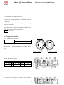
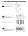
4.3 Inspect the valve clearance as specified in the figure
below with the feeler gauge
Cylinder 1
Cylinder 2
Cylinder 3
Cylinder4
IN
EX
IN
EX
IN
EX
IN
EX
O
O
O
—
—
O
—
—
4.4 Rotate the camshaft for a round to the position as
indicated in the figure, and then measure the valve
20
of
Exhaust
Gear
of
Intake
Chery QQ Service Manual
clearance once again:
Cylinder 1
Cylinder 2
Cylinder 3
Cylinder 4
IN
EX
IN
EX
IN
EX
IN
EX
—
—
—
O
O
—
O
O
If the clearance exceeds the standard value, adjust it by
replacing the adjustment gasket.
Notice: The position at which the measurement result
exceeds the standard value as well as the measurement
result should be recorded.
4.4.1 Rotate the camshaft and make the cam head of the
cylinder which exceeds the standard value faces upwards
and the opening of the valve tappet face inwards.
4.4.2 Rotate the crankshaft and press down the valve
tappet with the crown head of the cylinder cam.
4.4.3 As indicated in the right figure, put special tools on
and around the valve tappet from the inside of the cylinder
head, and then rotate the crankshaft so that the crown head
of the cam face upwards. Press the valve tappet with
special tools and hold on.
4.4.3.1 Pry out the adjustment gasket with screw driver,
remove the gasket inside with magnet.
4.4.3.2
Adjust the thickness of adjustment gasket with
21
Mechanical Part of SQR 472Engine
Chery QQ Service Manual
Mechanical Part of SQR 472Engine
micrometer caliper.
4.4.3.3
①
②
Select the gasket on the basis of the standard
value of valve tappet
Intake valve
Select gasket thickness = Unload thickness +
(Measured valve clearance -0.25mm)
Exhaust valve
Select gasket thickness = Unload thickness +
(Measured valve clearance -0.25mm)
[Reference] The 32 kinds of gasket with different
thickness are listed in the following table:
2.18
2.40
2.62
2.20
2.42
2.64
2.22
2.44
2.66
2.24
2.46
2.68
2.26
2.48
2.70
2.28
2.50
2.72
2.30
2.52
2.74
2.36
2.58
2.80
2.32
2.54
2.76
2.38
2.6
4.4.3.4 Adjust the valve clearance with selected
adjustment gasket.
Notice: Install the adjustment gasket with its identification
mark facing downwards.
Low
4.4.3.5 Rotate the crankshaft so that the crown head of
the cam faces downwards and presses down the the valve.
Pick up the special tool.
4.4.3.6 Rotate the crankshaft for 2-3 rounds and confirm
once again the valve clearance. If it is still beyond the
scope of standard value, adjust and inspect the valve
clearance according to the operation specified in 4.1-4.4.
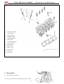
3) Cylinder Head
1. Structure Diagram
22
Chery QQ Service Manual
1
Spark plug 20±1Nm
2
Cylinder Head
3
Weather Strip I
4
Cylinder cushion
5
Adjustment gasket
6
Valve tappet
7
Valve spring retainer
8
Valve spring seat
9
Valve Spring
10 Intake valve
11 Exhaust valve
12 Valve oil seal
13 Valve seat
14 Valve guide
Mechanical Part of SQR 472Engine
※: Components which may not be
reused
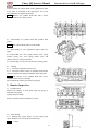
2. Disassembly
2.1 Disassembly of spark plug
2.2 There are 8 boltes on the cylinder head. In the course
23
Chery QQ Service Manual
of the assembly of cylinder head, slowly tighten these bolts
in the order as indicated in the right figure for several
times untill ther are tightened properly.
Notice: Remove the cylinder head bolts with a torque
socket wrench in the contrary order.
2.3 Disassembly of cylinder head and cylinder head
gasket
Notice: The cylinder head gasket is nonreusable.
2.4 Disassembly of valve adjustment gasket and valve
tappet
2.5 Disassemble the valve spring retainer lock, spring
retainer, spring seat, valve spring, intake valve, and
exhaust Valve etc with special tools.
2.6 Disassembly of valve oil seal and valve spring gasket
2.7 Cleanup
2.7.1 Clean the carbon dust on the valve.
2.7.2 Clean the bottom surface of cylinder head and the
surface of intake and exhaust manifold with scraper knife.
Notice: The surface of the cylinder head may not be
scratched in the course of cleanup.
Do not pollute the intake port and water passage.
3. Routine Inspection
3.1 Cylinder Head
Measure the flatness at each point with ring gauge as
indicated in the figure.
Cylinder head: 0.10mm
Surface of intake/exhaust manifold: 0.10 mm。
3.2 Valve Spring
3.2.1 Measure the square degree of valve spring with
square. Replace if it exceeds the specified value.
Limit: 1.2mm
24
Mechanical Part of SQR 472Engine
Chery QQ Service Manual
3.2.2
Mechanical Part of SQR 472Engine
Measure the free state of the spring.
Standard value:
37mm
3.3 Inspection of valve
3.3.1 Check if it is deformed or abrades.
Inspection of valve
Standard value
Limit:
0.10
IN
0.85~1.41
—
EX
1.07~1.36
—
IN
1.0±0.2
0.75
EX
1.0±0.2
0.75
Item
Width of seal
Thickness of top
of valve
Unit: mm
Thickness
Top
3.3.2 Check the clearance of valve guide and valve stem.
3.3.2.1 Measure the inside diameter of valve guide with
dial gauge, the outer diameter of valve stem with
micrometer caliper.
3.3.2.2 Figure out the difference of measured values and
the clearance. If the clearance is beyond the specified
value, replace valve or guide.
Notice: As can be seen from the right picture, at measuring
point, work out the clearance of last abrasion part.
Item
Standard value
Limit: 0.10
Valve guide inside
diameter(mm)
φ5.0
—
Valve guide outer
diameter(mm)
φ5.0
—
IN
0.056~
0.020mm
0.07
EX
0.066~
0.030mm
0.08
Clearance
of
Measurement
Position of
Diameter
Outer
Measurement
Point
Measurement of Valve Guide Inside Diameter
Measurement Point
25
Chery QQ Service Manual
Mechanical Part of SQR 472Engine
3.3.3
Replacement of valve guide.
3.3.3.1 Heat the cylinder head with hot water to 80-100
℃.
3.3.3.2 Take out the valve guide from one side of
combustion chamber with special tool, as can be seen from
the right picture.
Notice: The removed valve guide may not be reused.
The intake valve guide and the exhaust valve guide may
not be mis-installed.
IN Use
3.3.3.3 Mount the new valve guide with special tool at
the place as can be seen from the right picture.
Notice: strike the conduit slowly to the position in the
cylinder head; do not strike too far and be careful for size.
The height of the part of valve guide struck into the
cylinder head:
Type
EF
Item
GL, ZL, RL, GS, ZS
Height (mm)
IN
13.71±0.25
EX
12.11±0.25
3.3.3.4 Rub the inside diameter with reamer to reach the
standard clearance value.
3.3.4 Assorted surface of valve
3.3.4.1 Spread with red lead on the assorted surface of
valve. Do not rotate the valve but press lightly and check
the assortment and width.
26
EX Use
Chery QQ Service Manual
3.3.4.2
Mechanical Part of SQR 472Engine
Repair of valve seat insert
Notice: The repair of valve seat is always conducted in
the course of the inspection of valve’s fitting position. The
surface repaired should be free from any breakage. Take it
out slowly after the inspection.
3.3.4.3 45wimble surface is assorted standard value.
3.3.4.4 Inspect the fitting position of the valve. The best
position is the center of the valve. If no the valve should be
adjusted.
3.3.4.5 Cut wimble surface at the center of assorted
position with inner 70and outer 30
3.3.4.6
Prepare for polishing of valve seal.
3.4 Assembly of cylinder head
3.4.1 Cylinder head
Pay attention to the following for installing the other
auxiliary part of cylinder head:
3.4.2 Protective tube of spark plug
1. Press the protective tube of spark plug into the
protective tube hole on the cylinder head with the special
auxiliary tool. Before pressing, spread the protective tube
with sealant. The pressing depth is indicated in the right
figure.
Notice: Pay attention to the pressing depth and the
uprightness to top of cylinder head when pressing.
During pressing, the protective tube can not be deformed,
or leaking will be occurred at the cylinder head cover.
Protective Tube of Spark Plug
27
Chery QQ Service Manual
3.4.3
Installation
3.4.3.1 Assembly of valve spring washer and valve oil
seal
3.4.3.1.1 Clamp the special auxiliary tool on the top of
valve stem and spread oil around the auxiliary tool and the
inner of new valve oil seal. Then mount it at the position as
can be seen from the picture and pull out the mounting
auxiliary tool of valve oil seal.
[Reference]
Mechanical Part of SQR 472Engine
Auxilary Tool of Valve Spring Assembly
Valve
Valve Oil Seal
Assembly Lower Surface of
After being pressed down, the size of
the oil seal should comply with the value
indicated in the right figure.
Valve Spring
3.4.3.2 Assembly of intake valve and exhaust valve
3.4.3.2.1 Assembly of valve spring.
Notice: The painting is used for recognizing the different
suppliers, so the same engine should use the valve spring
with same painting.
Painting
3.4.3.3 Assembly of valve keeper
Warning: Operate with goggle for protecting the eyes.
·Be care for spring jumping out.
After assembly of valve spring and its seat, press the valve
spring with special tool and mount the valve keeper.
3.4.3.4 Assembly of valve tappet and valve clearance
adjustment gasket
3.4.3.5 Mount the cylinder head gasket and recognize
the direction of front and back.
3.4.4
Assembly of dust seal and cylinder head
28
Chery QQ Service Manual
assembly
3.4.4.1 Spread a little oil on the flange side of bolt and
threaded part
Mechanical Part of SQR 472Engine
Oil
Position
3.4.4.2 Tighten the cylinder bolts in the order indicated
in the right figure for 3 times till the torque reaches the
specified value. The tightening torque for each time is set
forth as follows:
First time: 30±2Nm; second time: 50±3Nm; third time:
70±3.5Nm
Torque: 70±3.5N.m
3.4.4.3 Mount spark plug
Torque: 20±1Nm
Notice: Tools should be vertical to prevent the protective
tube of spark plug from distorting, or the oil will leak.
29
Spread
Chery QQ Service Manual
Mechanical Part of SQR 472Engine
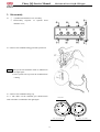
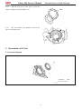
4) Water Pump
1. Structure Diagram
Components
①
②
③
may not be reused
O-ring (nonreusable)
Water pump body
Dust seal
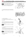
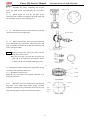
2. Disassembly
2.1.○
1 Disassembly O-ring
Notice: The O-ring is nonreusable.
2.2 Screw off 3 bolts and disassemble water pump body.
2.3. Disassembly of dust seal
3. Cleanup
3.1 Clean water pump joint surface.
4. Routine Inspection
4.1 Check if it is deformed.
4.2 Rotate it with hand and inspect whether the rotor
rotates and is lubricated well.
5
which
Assembly
5.1 Mount Dust seal.
5.2 Mount Water Pump Body; torque: 25±1.5N.m.
5.3 Mount The New O-ring.
30
Chery QQ Service Manual
Mechanical Part of SQR 472Engine
5) Oil Pump
1. Structure Diagram
Components
which
may not be reused
① Torque for oil pan bolt: 8±2 N.m
② Oil collector
③ Oil collector spacer (nonreusable)
④ Oil pump
⑤ Oil pump spacer (nonreusable)
⑥ Rear oil seal bracket
2
Disassembly
2.1 Screw off the bolts and nuts, and then remove the oil
pan from the cylinder body with special tool (The engine is
placed on the disassemble shelf upside down).
Notice: Don’t make the oil pan flange deform.
31
Chery QQ Service Manual
2.2 Remove the engine oil drainer, engine oil collector
gasket
Notice: The oil collector gasket is nonreusable.
2.3 Remove the engine oil pump assembly and the engine
oil pump gasket.
2.4 Remove the rear oil seal bracket.
3. Cleanup
3.1 Remove the old cushion from the oil pan, oil pump
and oil pan bracket with a scraper or shovel.
Notice: Don’t let the fragment of the cushion fall into the
cylinder.
32
Mechanical Part of SQR 472Engine
Chery QQ Service Manual
4
Mechanical Part of SQR 472Engine
Disassembly and Assembly of Engine Oil Pump
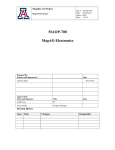
4.1 Structure Diagram
①
Seal Ring
②
Engine Oil Pump Cover Sheet
③
Engine Oil Pump Inner Rotor
④
Engine Oil Pump Outer Rotor
⑤
Cotter Pin
⑥
Oil Drain Valve Spring base
⑦
Oil Drain Valve Spring
⑧
Slide Block
⑨
Crankshaft Front Oil Seal
⑩
Engine Oil Pump Housing
※ : Components which may
not be reused
Unit: N·m(kg·cm)
4.2 Disassembly
4.2.1 ① O-ring
Notice: The O-ring is nonreusable.
4.2.2 Remove the oil pump cover
Notice: If the screws are tightened, use a screw driver
to remove them as indicated in the figure.
4.2.3 Remove the inner rotor, outer rotor of the engine
oil pump.
33
Chery QQ Service Manual
4.2.4
Mechanical Part of SQR 472Engine
Remove the cotter pin
Notice: The cotter pin is nonreusable.
Notice: When removing the cotter pin, be careful not to
let the spring or the spring seat spring out or fall off
abruptly.
Relief Valve
Slide Block
4.2.5
Remove the spring seat of the oil pressure relief
valve for the engine oil pump, the coil spring, oil pump
and oil pressure relief valve etc.
Relief Spring
Spring Seat
4.2.6
Remove the front crankshaft oil seal.
Notice: The oil seal removed may not be reused.
4.3
Routine Inspection
Mark
4.3.1
Inspect the engine oil pump for clearance.
4.3.1.1 According to the marks for inner gear and outer
gear in the engine oil pump, put the gears into the engine
oil pump that is in the cylinder block.
4.3.1.2 Measure the clearance between the inner and
outer gears with a feeler gauge
Standard value: 0.05-0.18mm (average value of 9
positions)
Limit:
0.35 mm
34
Chery QQ Service Manual
Mechanical Part of SQR 472Engine
4.3.1.3 Measure the clearance between the rotor and
pump body.
Standard value: 0.10-0.181mm
Limit: 0.25 mm
4.3.2
Inspect the oil pressure relief valve
4.3.2.1 No abrasion or scrape shall be found on the oil
pressure relief valve.
4.4
Installation
4.4.1 After the lip of the new oil seal for front crankshaft
is spread with engine oil, fix it with a special tool.
Special Tool
Notice: ·Use new oil seal
·The oil seal should be left less than 0.5 mm at its
outer edge after it is pressed down.
Pressed Direction
Inner Side
Oil Seal
Below 0.5mm
4.4.2 Assembly of the oil pressure relief valve for engine
oil pump and the cotter pin.
Notice: The cotter pin is nonreusable.
35
Chery QQ Service Manual
4.4.3
When the outer gear or inner gear is put into the
engine oil pump, its mark should be seen.
Mechanical Part of SQR 472Engine
Mark
4.4.4
The new weather strip should be fixed in the
groove of oil pump cover.
5. Disassembly of Oil Seal
5.1 Structure Diagram
Components
which
may not be reused
36
Chery QQ Service Manual
5.2
Mechanical Part of SQR 472Engine
Disassembly
5.2.1 Remove the rear crankshaft oil seal with a
screwdriver.
Notice: The rear oil seal of the crankshaft is nonreusable.
Lip
5.3
Inspection
Inspect the oil seal for damage and the abrasion at its lip.
5.4
Assembly of oil seal
5.4.1
Spread engine oil over the lip of the new oil seal.
5.4.2
Mount the oil seal with special tool as indicated
in the right figure
Special Tool
Special Tool
6. Assembly
Glue Spread Line
6.1 Assembly of the oil seal seat
Spread sealant over the oil seal seat as shown in the right
figure.
Grease: Loctite 5699
Notice: Spread the liquid sealant on the position of the
oil seal base which is to contact with the cylinder body,
and make sure the width of the sealant is 3-4mm.
Torque: 25±1.5N.m
6.2 Assembly of the new engine oil pump gasket and the
engine oil pump assembly.
Torque: 20±1.5N.m
6.3
Assemble the new engine oil collector gasket and the
37
Chery QQ Service Manual
Mechanical Part of SQR 472Engine
engine oil drainer
Torque: 6±1N.m
6.4 Assembly of the oil pan
6.4.1 Clean up the joint surface between the oil pan with
the cylinder.
6.4.2 Spread sealant, then assemble it.
Grease: Loctite 5699
Notice: ·The sealing line should be unbroken with its
diameter being ф3-4mm
·Assembly should take place fifteen minutes
after glue-spreading.
6.4.3 Tighten the bolts in the middle first up to the
specified torque, then the bolts beside them as shown in
the right figure.
Torque: 6±1N.m
Front
38
Rear
Chery QQ Service Manual
Mechanical Part of SQR 472Engine
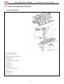
6) Crank Connecting Rod Mechanism
1
Structure Diagram
Components which may
not be reused
① Connecting rod cover
② Connecting rod bushing
③ Piston connecting rod assembly
④ Main bearing cap
⑤ Crankshaft
⑥ Crankshaft bearing bushing
⑦ Thrust plate
⑧ Cylinder body
⑨ First ring
⑩ Second ring
⑾ Steel tape combined oil ring
⑿ Piston
⒀Connecting rod
⒁ Piston pin
39
Chery QQ Service Manual
2
Mechanical Part of SQR 472Engine
Disassemble of Crank Connecting Rod Mechanism
2.1 Inspect the axial momentum of the connecting rod
2.1.1 Measure the axial clearance with a dial gauge or
feeler gauge.
Standard value: 0.15-0.25mm
Limit: 1.2mm
2.2 Inspect the connecting rod bushing for its radial
clearance.
2.2.1 Remove the bushing cap.
Notice: The components of each cylinder shall be placed
in order.
2.2.2 Clean the bearing bushing and the axle.
2.2.3 Conduct radial adjustment for the axial diameter of
connecting rod with clearance gauge.
Tighten the bushing cap with specified torque.
Torque: 40±2N.m
Notice: The crankshaft may not rotate.
2.2.4 Remove the bushing cap, measure the maximum
thickness of the searcher.
Standard value: 0.020-0.044 mm
Limit: 0.07 mm
40
Chery QQ Service Manual
Mechanical Part of SQR 472Engine
2.2.5
If it is beyond the limit, replace the bearing
bushing.
Notice: Replacing the bearing bushing with the product
of the same manufacturer’s brand. The thickness of the
connecting rod bushing which meets the requirements of
clearance = diameter of big end hold – axial diameter of
connecting rod – standard value of bearing bushing
clearance
Connecting Rod
Connecting Cover
2.2.6
Remove the connecting rod bearing cap and the
connecting rod bearing bushing
2.2.7
Put vinyl-resin protecting jacket on the threaded
part of the connecting rod bolt so as to prevent the bolts
from scraping the cylinder hole and the crannkshaft
connecting rod journal, and then disassemble the piston
connecting rod by using the hammer handle striking it out.
Protection Sleeve
2.3 Inspect the axial clearance of crankshaft
2.3.1 Measure the axial clearance of the crankshaft with
a dial gauge, if it is beyond the limit, it is necessary to
replace the axial thrust plate or the crankshaft.
Standard value: 0.089-0.211mm
Limit: 0.30mm
Item
Standard value
1.9-0.11-0.03
41
Chery QQ Service Manual
Mechanical Part of SQR 472Engine
2.4 Inspect the crankshaft for its radial clearance.
2.4.1 Remove the crankshaft bearing cap by softly
tapping with a resin hammer.
2.4.2 Clean the inside and surface of the bearing bushing,
the inside and surface of the bearing cap, the cylinder wall
and journal. Inspect them for abrasion and damage
carefully.
2.4.3 Adjust the radial clearance of the crankshaft with a
clearance gauge, and tighten the bearing bushing cover
bolts with the specified torque.
Torque: 70±3.5N.m
Notice: After tightening the bolts, the rotating torque of
the crankshaft should be less than 1Nm
(The torque of crankshaft without piston connecting rod)
Protection Sleeve
Clearance Gauge
2.4.4 Remove the bearing cap and measure the maximum
width with a clearance gauge. If the measurement result
exceeds the limit, replace the bearing bushing.
Standard value: 0.025-0.069mm
Limit:
0.10mm
Width Compare of Clearance Gauge
2.4.5 Remove the main bearing bushing cap of the
crankshaft, crankshaft, crankshaft bearing bushing and
crankshaft axial thrust plate
Notice: Tighten the bolts for the crankshaft bearing cap
in the order shown in the right figure. Tighten the bolts for
three times, then the torque must be up to the specified
value.
42
Chery QQ Service Manual
Mechanical Part of SQR 472Engine
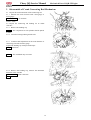
2.5 Disassembly and assembly of the piston and
connecting rod assembly
2.5.1
Remove the first ring, second ring and the oil
ring with a pair of piston ring moving pliers.
Notice: Don’t get the piston and piston ring of each
cylinder confused.
2.5.2
Remove the piston, connecting rod and the
piston pin with special tool.
Special Tool
Disassemble the piston pin with special tool as indicated in
the right figure.
① As indicated in the right figure, disassemble the piston
which is at the state mentioned above with special
tools. Remove the piston pin with special tool, and
then remove the piston and the connecting rod.
3
Special Tool
Cleanup
3.1 Cylinder Body
Warning:
In the course of cleanup, protect your eyes
with eyeglass.
3.1.1
Clean up the cylinder body, cylinder head, oil
pan, oil pump and the oil seal with a flat blade.
3.2 Piston
Warning:
In the course of cleanup, protect your eyes
with eyeglass.
3.2.1
Use an old ring to remove the carbon in ring
groove.
3.2.2
Remove the carbon of parts with scavenger.
Notice: Don’t use hard articles such as metal brush.
43
Chery QQ Service Manual
4
Mechanical Part of SQR 472Engine
Routine Inspection
4.1 Cylinder Body
4.1.1 Inspect the top surface of cylinder body for its
flatness
(1) Measure at the six points shown in the right figure
with a ruler and a feeler gauge.
Limit:
0.08mm
4.1.2 Use of bore gauge
Measure the cylinder bore at the positions as indicated in
the right figure with a bore gauge, and figure out the
difference between the maximum value and the miximum
value. If the difference exceeds the limit, repair or replace
the cylinder.
Limit: 0.03mm
[Reference] Roundness: A-B or a-b
Cylindric degree: A-a or
[Reference] Standard
diameter
φ72.00-72.01mm
Upper Stopper Position of Piston
Lower Stopper Position of Piston
of
cylinder:
4.2 Piston
4.2.1
Inspect the piston pin hole for its clearance
Measure the piston pin at several positions with a
micrometer caliper shown in the figure, make the
maximum value as the diameter of pin.
Measurement
Piston Pin
4.2.2
Measure the diameter of piston pin at several
positions with an inner-diameter dial gauge as shown in the
figure, make the minimum value as the diameter of the pin
hole.
Work out the clearance with the difference between the
pin diameter and pin hole diameter, if the difference is
beyond the standard value, replace the piston pin or piston.
Standard value: 0.004-0.009mm
Limit: 0.015mm
44
Position
of
Chery QQ Service Manual
4.2.4 Measure the diameter of the piston
4.2.4.1 Measure at about 11 mm to the bottom of the
piston, along the direction vertical to the piston pin.
φ 72
0.013
Standard value:
0.025
4.2.5 Inspect the clearance between the piston ring and
the ring gloove
4.2.5.1 Measure around the ring gloove with a piston
ring and a feeler gauge
Standard value
(mm)
Limit
(mm)
First ring
0.03~0.06
0.12
Second
ring
0.03~0.06
0.11
4.2.6
Inspect the end clearance of piston ring
4.2.6.1 Put the piston ring 45mm below the top surface
of the cylinder hole. Press down the piston ring with the
piston head, and then measure the opening with a feeler
gauge.
Standard value
(mm)
Limit
(mm)
First ring
0.25-0.40
0.65
Second
ring
0.35~0.50
0.65
Oil ring
0.20~0.70
1.00
45
Mechanical Part of SQR 472Engine
Chery QQ Service Manual
4.2.7
Inspect the clearance between the piston and
cylinder wall
4.2.7.1 Measure the inner diameter of the cylinder and
the outer diameter of the piston at the positions as
indicated in the right figure. If the measurement results
exceed the limit, replace the piston or cylinder.
Standard value: 0.018~0.030
Limit: 0.10
[Reference] The clearance between the piston and cylinder
bore is controlled by the difference between the minimum
inside diameter of piston hole and the maximum outer
diameter of piston.
4.2.7.2 After replacing the piston or the cylinder body,
confirm the clearance again
Standard value: 0.018~0.030
Measurement position of piston
Outer Diameter
Measurement
position of piston
Inner Diameter
4.3 Crankshaft
4.3.1 Inspect the proper alignment of the main axle
diameter.
4.3.1.1 Measure the proper alignment with a dial gauge,
if the proper alignment is beyond the limit, replace the
crankshaft.
Limit: 0.03mm
Notice: The bending value should be equal to
one-second the run-out value of crankshaft rotating one
circle.
4.3.2
Inspect the crankshaft for the abrasion.
4.3.2.1 Measure the connecting rod journal at the
positions indicated in the left figure with a microcaliper,
and figure out the roundness and cylindricity.
Limit: 0.005mm
4.3.2.2 Measure the connecting rod journal at the
positions indicated in the right figure with a microcaliper,
and figure out the roundness and cylindricity.
Limit: 0.004mm
5
Mechanical Part of SQR 472Engine
Assembly of Crank Connecting Rod
mechanism
5.1 Assembly of the piston connecting rod
46
Chery QQ Service Manual
Mechanical Part of SQR 472Engine
5.1.1
Assemble the piston, connecting rod and the
piston pin with special tool following the instructions
below:
5.1.1.1 Spread engine oil over the pin hole of the
connecting rod, assemble according to the group mark and
direction mark of piston and connecting rod.
Mark Forward
5.1.1.2 Assemble the piston and the connecting rod with
special tools shown in the right figure.
Align and Straight
5.1.1.3 Adjust and assemble the piston and connecting
rod as indicated in the right figure. Spread the piston pin
with oil and then assemble the piston and connecting rod
with a oressing machine.
Notice: When pressing in the piston pin, make sure the
fitting direction is correct.
·When the piston pin is pressed into the piston, the
small end of the connecting rod should be heated
to 300℃, and the pin should be aligned properly.
Section Shape
Mark
0
5.2 Install the first and second pistion ring and the oil ring
according to the following instruction:
5.2.1 Installation of piston ring
Make the side with marks face upwards, and then fix it
with piston pin tools.
1st Ring
2nd Ring
Oil Ring
Lower Blade
5.2.2
Mount the steel tape combined oil ring (bushing
ring lower, lower blade, upper blade) firstly, and then
mount the second gas ring, and finally mount the first gas
ring. Opening angles of rings are shown in the figure:
1st Ring
2nd Ring
Front
Rear
Bushing
Ring
Upper Blade
47
Chery QQ Service Manual
Mechanical Part of SQR 472Engine
5.3 Resemble the crankshaft main bearing cap,
crankshaft, crankshaft bearing bushing and the crankshaft
axial thrust plate, pay attention to the following:
5.3.1 Assembling the bearing bushing, its raised thrust
block should fit into the locating groove in the cylinder
body.
Notice: The
manufacturer.
bearing bushing is
Thrust Plate
from the same
Oil Tank
Spread Oil on the surface of
Bearing Bushing
5.3.2 Spread the crankshaft bearing bushing (upper
piece) with oil before assemble the crankshaft
Outer Forward of Oil
Tank
5.3.3 Mount the thrust plate on the cylinder body bearing
base and make sure that the side with oil gloove
(crankshaft shank) face outwards.
Notice: Spread the side of oil glove with oil
5.3.4 Fix the crankshaft bearing bushing (lower piece) in
the bearing cap, the bearing bushing should fit into the
thrust groove.
Forward Mark
5.3.5 Spread engine oil over the friction surface of
crankshaft bearing bushing (lower piece), assemble the
bushing according to the mark forwards in the main
bearing cap of the crankshaft.
Axle Diameter Mark
5.3.6 Spread oil over the bolts, within three or two times,
tighten them with specified torque.
Torque: 70±3.5N.m
5.3.7 Rotate the crankshaft after assembly, it should
rotates swiftly, the rotating torque should be less than
1Nm.
48
Chery QQ Service Manual
Mechanical Part of SQR 472Engine
5.4 Assemble the piston and connecting rod assembly,
connecting rod bearing bushing and the connecting rod
bearing cap, pay attention to the following:
5.4.1
The opening of compression ring and the
opening of oil ring should be in the specified direction.
5.4.2
The bolts of the connecting rod should be
covered with nylon sleeves for fear of scraping the
cylinder body and the axle.
5.4.3
The surfaces of piston and connecting rod and
other surfaces where relative motion exists should be
spread with engine oil.
5.4.4
Confirm the mark forwards of the piston and
strike it into the cylinder body with the piston ring striking
tool.
Notice: The cylinder number of the piston and
connecting rod assembly should be in accordance with the
cylinder number.
5.4.5
Assemble the connecting rod bearing cap and the
connecting rod bushing, pay attention to the following:
5.4.5.1 Put the cover on the bolt as per the mark
forwards, spread a little engine oil over the joint surface
between the nut and its seat.
5.4.5.2 Tighten the right nut and the left nut alternatively
for several times with specified torque.
Forward Mark
Torque: 40±2N.m
Notice: The connecting rod and the connecting rod
bushing should be of the same subassembly:
.
49
Chery QQ Service Manual
Mechanical Part of SQR 472Engine
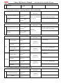
Chapter 3. Table of Main Fit Clearance for SQR472 Engine SQR472
1
Clearance between Cylinder Hole and Piston Skirt (Piston to Cylinder Clearance)
Name of Component
Size and Tolerance
φ72 0
0.015
Piston skirt
φ72 -0.025
Size and Tolerance
Crankshaft main journal
φ42h6–0。016
Bearing bushing
2
Bore of cylinder main bearing
φ46F6 +0.025
0.005
Group S: F720.005
0.01
Clearance or Value of
Interferenc
Remark
Clearance 0.025~0.069
- 0.006
+
0.041
Clearance of Crankshaft Connecting Rod Bearing
Crankshaft
journal
connecting
Size and Tolerance
rod
Clearance or Value of
Interferenc
Remark
0
φ37h6 -0.016
0
Bearing bushing
1.5 -0.006
Bore of connecting rodbig
end bearing
φ40F6 +0.025
Clearance 0.025~0.069
+
0.041
Clearance between Piston Pin and Piston Pin Hole
Name of Component
5
Group X: F720
0
Name of Component
4
Remark
Clearance of Crankshaft Main Bearing
Name of Component
3
Divided into two groups:
Clearance for group X:
0.019mm~0.03mm
Clearance of group S:
0.018mm~0.029mm
+0 . 01
Cylinder hole
2
Clearance or Value of
Interferenc
Size and Tolerance
Piston Pin Hole
+
0.007
φ18 +0.002
Piston pin
φ18 -0.004
0.001
Clearance or Value of
Interferenc
Remark
Divided into twogroups
Clearance for group A:
0.004 mm~0.0085mm;
Clearance for group B:
0.0045mm~0.009 mm
Notice: When installed
with hand, the piston pin
may pass through the
piston pin hole smoothly
without
any
obvious
obstruction, otherwise the
piston pin should be
replaced.
Inteference between Piston and Small End of Connecting Rod
Name of Component
Connecting rod small end
hole
Size and Tolerance
Clearance or Value of
Interferenc
Value of Interferenc
0.021~0.043
0.026
φ18 -0.044
50
Remark
Chery QQ Service Manual
0.001
Piston Pin
6
φ18 -0.005
Fit Clearance between Connecting Rod Body Hole and Bolt Bar
Name of Component
Connecting rod body hole
Clearance or Value of
Interferenc
+
0.015
φ8.08 H7 0
Value of Interferenc
0.008~0.032
Remark
The hole should be processed along
with the connecting rod body.
φ8.08 S6 +0.023
Fit Clearance between Connecting Rod Cover Hole and Bolt Bar
Name of Component
Connecting rod cover hole
Size and Tolerance
Clearance or Value of
Interferenc
+
0.015
φ8.08 H7 0
0.005
Bolt bar
8
Size and Tolerance
+
0.032
Bolt Bar
7
Mechanical Part of SQR 472Engine
Clearance
0.005~0.029
Remark
The hole should be processed along
with the connecting rod body.
φ8.08 f6 -0.014
Radial Clearance of Camshaft Bearing
Name of Component
Cylinder Head
Camshaft
Size and Tolerance
φ26H7
Clearance or Value of
Interferenc
1st bearing cap
0.021
0
Clearance
0.020~0.054
0.020
φ26f6 -0.033
Intake
Cylinder Head
Camshaft
Cylinder Head
Camshaft
φ23H7
1st bearing cap
2nd, 3rd, 4th & 5th bearing caps
0.021
0
Clearance
0.020~0.054
0.020
φ23f6 -0.033
φ29H7
Remark
2nd, 3rd, 4th & 5th bearing caps
1st bearing cap
0.021
0
Clearance
0.020~0.054
0.020
φ29f6 -0.033
1st bearing cap
Exhaust
Cylinder Head
Camshaft
9
φ23H7
0.021
0
Clearance
0.020~0.054
0.020
φ23f6 -0.033
2nd, 3rd, 4th & 5th bearing caps
2nd, 3rd, 4th & 5th bearing caps
Fit Clearance between Tappet Hole and Tappet
Name of Component
Cylinder Head Hole
Tappet
Size and Tolerance
Clearance or Value of
Interferenc
0.021
φ28H7 0
Clearance
0.020~0.054
0.020
φ28f6 -0.033
51
Remark
Chery QQ Service Manual
Mechanical Part of SQR 472Engine
Remarks: In the above tables, the capital letter and suffix following the sizes (For example, H7 of φ28H7) mean the
process precision, which are unconcerned with the maintenance and may be ignored in the course of maintenance.
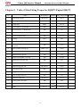
Chapter 4. Table
of
Measurement
Parameters
of
SQR472
EngineSQR472
No.
1
Measuring Items
Acceptance value Remark
Axial clearance of crankshaft
0.089-0.211mm
Assemble the crankshaft and tighten the
main bearing cap bolt
Mount the piston connecting rod
Torque of crankshaft
assembly and tighten the connecting
when rotating at
rod bolt
uniform speed
2
Installing timing belt and spark plug
≤1 Nm
≤5.5Nm
≤6Nm
≤26 Nm
Mount the valve, spring and camshaft (excluding timing belt
and spark plug) on the cyllinder head, tighten the camshaft
bolt, and then measure the torque of the camshaft rotating at
uniform speed
≤32 Nm
3
Distance between the outer edge of steel ball and the front end
of camshaft
5.65±0.5mm
4
Distance between the outer edge of steel ball and the rear end
of camshaft
8.65±0.5mm
5
Axial clearance of intake camshaft
0.10~0.179
6
Axial clearance of exhaust camshaft
0.10~0.253
7
Jumping amount of installation surface of flywheel wearing
piece
0.10mmmax
8
Protrusion height of crankshaft woodruff key
2~2.20mm
9
Intake valve clearance
0.18±0.05mm
10
Exhaust valve clearance
0.25±0.05mm
11
Tension of timing belt (When the middle part of the rigth side
is pressed down for 4-5mm)
200~280N.m
12
Compression pressure of cylinder
13
Tension of generator belt ( When the part between the
generator and water pump is pressed down for 4-5mm)
14
Refilling amount of engine oil (including filter)
10~14bar
98N.m
3.5 Liter
52
Chery QQ Service Manual
Mechanical Part of SQR 472Engine
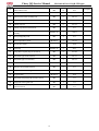
Chapter 5. Table of Main Fitting Torque for SQR472 EngineSQR472
No.
Name
1
Main bearing cap bolt
2
Specification
Quantity Fixing Torque (Nm) Remark
M10X1.25
10
70±3.5
Connecting rod cover bolt
M8X1
8
40±2
3
Oil pump bolt
M8X1
6
20±1.5
4
Nut (oil collector – oil ppump)
M6
2
6±1
5
Bolt (oil collector – cylinder body)
M6
1
6±1
6
Water pump bolt
M8X1
6
25±1.5
7
Rear oil seal bracket bolt
M8
5
25±1.5
8
Drain plug
M12
1
45±3
9
Oil pan bolt
M6
19
6±1
10
Bolt connecting exhaust camshaft with flange
(hexagonal)
M6
4
6±1
11
Exhaust camshaft locking nut
M40X1.5(L)
1
100±5
12
Cylinder head bolt
M10X1.25
10
70±3.5
13
Camshaft bearing cap bolt
M6
19
9±1
14
Cylinder head chamber cover bolt
M6
8
4.5±0.5
15
Camshaft position sensor bolt
M8
1
10±1
16
Bolt (knock sensor)
M8
1
20±1.5
17
Camshaft timing gear bolt
M12X1.25
1
100±5
18
Tension pulley bolt
M10
1
25±3
19
Timing cover bolt
M6
7
6±1
20
Engine oil gauge pipe bolt
M6
21
Flywheel assembly bolt
22
Thermoregulator shell bolt
23
Oil filter conncetor
3/4"-16
40±2.5
24
Oil filter
3/4"-16
20±1.5
53
6±1
M10X1.25
6
70±3.5
M8
2
10±1
Chery QQ Service Manual
Mechanical Part of SQR 472Engine
25
Intake/exhaust stud
M8
16
10±1
26
Intake pipe nut
M8
8
25±1.5
27
Ignition coil bracket assembly bolt
M8
2
20±1.5
28
Front lifting lug bolt
M8
2
20±1.5
29
Exhaust pipe nut
M8
8
25±1.5
30
Exhaust pipe thermal shroud bolt
M6
3
6±1
31
Bolt on crankshaft pulley & torsional damper
assembly
M12X1.25
1
100±5
32
Water pump pulley bolt
M6
4
6±1
33
Water temperature sensor
M12X1.5
1
15±1.5
34
Oil pressure switch
1
30±2
35
Spark plug
M14X1.25
4
20±1
36
Fixing Bolt of spark plug cover board)
M6
8
2.5±0.5
37
Bolt (intake pipe front bracket)
M8
1
20±1.5
38
Bolt (intake pipe rear bracket)
M8
4
20±1.5
39
Bolt (throttle cable)
M6
2
6±1
40
Bolt (gas-oil spearator bracket)
M6
2
6±1
41
Bolt (throttle valve casing)
M6
4
6±1
42
Oxygen sensor
M18X1.5
1
40±2
43
Bolt (intake temperature & pressure sensor)
M4
1
3±1
44
Fixing bolt of fuel guide rail
M6
2
7±1
45
Ignition coil bolt
M6
3
5±1
54
Spread glue
Chery QQ Service Manual
Mechanical Part of SQR 472Engine
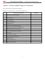
Chapter 6. Positions on SQR472 Engine to be Lubricated
Type of lubricating oil: Engine lubricating oil
Designation of lubricating oil: SAE10W/30-50(SF Class)
No.
Position to be lubricated
1
Joint surface of connectong rod bolt head
2
Screw of connecting rod bolt
3
Exicrcle of piston pin
4
Inner wall of piston pin hole
5
Piston and piston ring
6
Inner wall of cylinder hole
7
Crankshaft main neck
8
Connecting rod shaft neck
9
Upper & lower main bearing bushing (inside)
10
Upper & lower connecting rod bearing bushing (inside)
11
Crankshaft thrust plate (the side of oil gloove)
12
Front oil seal and crankshaft front oil seal journal
13
Rear oil seal and crankshaft rear oil seal journal
14
Valve seat hole
15
Valve tappet and valve pipe hole
16
Excircle and hole of valve tappet
17
Camshaft journal and bearing base hole
18
Camshaft driving gear
19
Edge and excircle of oil seal
20
Oil seal journal and oil seal base hole
21
Surface oil filter sealing gasket
55
Remark
Chery QQ Service Manual
Mechanical Part of SQR 472Engine
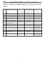
Chapter 7. Positions on SQR472 Engine to be Spread with Sealant
SQR472
Position to be spread with
No.
Form and amount of
Type of sealant
sealant
Remark
sealant (reference)
1
Joingt surface of oil pan
Loctite 5699
ф(3~4)mm
2
Rear oil seal bracket
Loctite 5699
ф(3~4)mm
3
Valve chamber cover
Loctite 5699
ф(3~4)mm
4
Joint surface if timing gear chamber
cover
Loctite 5699
ф(3~4)mm
5
Joint surface of camshaft cover
Loctite 5699
ф(3~4)mm
6
Sealing surface of the bowl shaped
plug of cylinder head
Loctite 11747
Spread uniformly
7
Flywheel bolt
Loctite 204
0.125(ml)×6
Pre-spread @3
Intake pipe stud
Loctite 262
0.125(ml)×7
The part screwed into
the cylinder head
Exhaust pipe stud
Loctite 262
0.125(ml)×6
The part screwed into
the cylinder head
Camshaft timing gear bolt
Loctite 243
0.2ml
Oil collector stud
Loctite 243
0.08(ml)×2
The part screwed into
the oil pump
Screw of thermoregulator shell
fixing bolt
Loctite 243
0.08(ml)×2
The part screwed into
the cylinder head
8
9
10
11
12
56