1
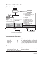
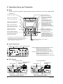
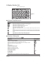
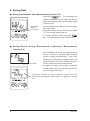
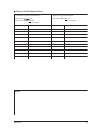
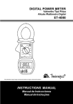
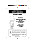
User’s
Manual
IM CW120P-E
CW120/121
CLAMP-ON POWER METERS
Operation Guide
Thank you for purchasing our CW120 or CW121 Clamp-on Power Meter. This
Operation Guide explains the fundamental operations of the CW120 and CW121 so
as to get you started using the CW120 or CW121 even if you are a first-time user.
For more information of measurement and details of each function, see the User’s
Manual, IM CW120-E. To ensure safe and correct use of the CW120 and CW121,
thoroughly read the handling precautions in User’s Manual, IM CW120-E, before
use.
Before starting measurement with your CW120 or CW121, fill in the Setting
Check Sheet in the back of this guide with your particular settings, to facilitate
setting on site without error.
Contents
1. Functions and Operation Flow ........................................................................ 2
2. Operation Keys and Terminals ........................................................................ 4
3. Display <Section 2.4> ..................................................................................... 5
4. Browsing Measured Values <Sections 8.2 and 9.3> ....................................... 6
5. Changing Range Settings <Sections 6.2 and 6.3> ......................................... 6
6. Changing Wiring Method <Section 6.4> .......................................................... 7
7. Changing Settings <Chapter 7> ...................................................................... 8
8. Saving Data ..................................................................................................... 9
9. Starting and Ending Integration <Section 9.2> .............................................. 10
10. Meanings of Messages <Section 2.4> .......................................................... 10
Setting Check Sheet ........................................................................................... 11
Throughout this manual, references to sections or chapters of the User’s Manual (IM
CW120-E) are enclosed in angle brackets, such as <Chapter 4>.
IM CW120P-E
3rd Edition May 2007(KP)
1. Functions and Operation Flow
● Schematic Function Diagram
Power-on
Measurement
screen
7.2.1
7.2.2
7.2.3
7.2.4
key
7.2.5
<Chapter 9>
Electric energy (watt-hour)
measurement
Start of
integration
<Chapter 8>
End of
integration
Instantaneous value
measurement
7.2.8 Setting integration start time
7.2.9 Setting integration stop time
Data saving
Data saving
Auto-saving
7.2.7 Setting output interval
7.2.6
7.2.7
7.2.8
7.2.9
7.2.10
7.2.11
7.2.12
7.2.13
7.2.14
7.2.15
7.2.16
7.2.17
key
<Chapter 7>
Setting device number
Loading/saving settings
Deleting file and formatting PC card
Clearing electric energy count (watt-hours)
and resetting system
Copying and clearing backup memory
contents
Setting date
Setting output interval
Setting integration start time
Setting integration stop time
Setting whether to save data to PC card
Selecting communication device
Making communication settings
Setting Communication protocol
Setting VT ratio
Setting CT ratio
Selecting probe to be used
Setting decimal point and unit of electric
energy (watt-hours)
Saving settings
File: AWTH000.CSV
External control terminals
Input
Output
Setting
screens
key
File: MWTH000.CSV
RS-232
7.2.2 Loading/saving setting File: WTH000.SET
Communication interface
(chosen when ordering)
RS-485
PC card
PC
Printer
PC
7.2.11 Selecting communication device
7.2.10 Setting whether to
save data to PC card
● On-screen Information (Measured Data)
Instantaneous value measurement
Item
Unit
Displayed Name
Rms voltage
Rms current
Active power
Reactive power
Power factor
Frequency
V
A
W
Var
—
Hz
V1, V2, V3 (differs depending on the wiring method)
A1, A2, A3 (differs depending on the wiring method)
W, W1, W2, W3 (differs depending on the wiring method)
Var, Var1, Var2, Var3 (differs depending on the wiring method)
PF, PF1, PF2, PF3 (differs depending on the wiring method)
Hz (input frequency of V1)
Electric energy measurement
Item
Unit
Displayed Name
Active electric energy
Wh
Wh, Wh1, Wh2, Wh3 (differs depending on the wiring method)
Regenerative electric energy
Wh
Only saved; not displayed
Six items of instantaneous value measurement
2
IM CW120P-E
● Basic Operation Flow
Connect power supply
to CW120/121
<Chapter 4>
Turn on power to
CW120/121
<Chapter 4>
Startup screens
Measurement
screen
<Chapter 4>
When no setting is needed
key
Setting screen
<Chapter 7>
key
Measurement
screen
key :Calls up wiring setting
:Calls up voltage range
key setting
key :Calls up current range
setting
Perform
wiring
<Chapter 6>
<Chapter 5>
(press 3 sec):
Check wiring for error
key
When skipping
wiring check
Check result
screen
<Chapter 5>
key
Measurement
Instantaneous value
measurement
Electric energy
measurement
IM CW120P-E
<Chapter 8>
<Chapter 9>
3
2. Operation Keys and Terminals
● Keys
Section numbers enclosed in angle brackets indicate references in the User’s Manual (IM
CW120-E).
Displays the voltage range.
Displays the wiring method (phase lines).
Displays the current range.
• Used to set and change the
wiring method (phase lines)
<Section 6.4>.
• Pressing this key for three
seconds accesses the wiring
check screen <Section 5.5>.
Used to set and change the
current range <Section 6.3>.
Used to set and change the
voltage range <Section 6.2>.
• Switches on/off the back light of
the LCD <Section 12.1>.
• Pressing this key for three
seconds locks the keys. To
unlock, press the key again for
three seconds or more <Section
12.1>.
Saves the measured data
during instantaneous value
measurement <Section 8.3>.
Integration status LED
indicator <Section 9.2>
Switches over the display
between the measurement and
setting screens <Section 7.1>.
Starts and stops integration;
press this key for one second
to start and stop integration
manually <Section 9.2>.
• In measurement screen:
Switches the display contents
<Sections 8.2 and 9.3>.
• In setting screen: Changes the
selection or number, or moves
the cursor position (flashing
digit) over digits <Sections 7.2>.
• In setting screen: Cancels a setting <Section 7.2>.
• In measurement screen: Pressing this key for three
seconds accesses the screen for clearing the
electric energy count <Section 9.2.3>.
Confirms an entry such as a change to a
setting <Section 7.2>.
● Input Connectors
Voltage input terminals Current input terminals
CW120: Supports from single-phase two-wire to
three-phase three-wire circuits
Voltage input terminals: N, V1, V2
Current input terminals: CH1, CH2
CW121: Supports from single-phase two-wire to
three-phase four-wire circuits
Voltage input terminals: N, V1, V2, V3
Current input terminals: CH1, CH2, CH3
● Side Panels
PC card eject button
PC card slot
Power switch
External control
RS-232 terminals
connector
Power supply connector
Model with RS-232 interface
4
PC card eject button
PC card slot
Power switch
RS-485 screw
terminals
Power supply connector
Model with RS-485 interface
IM CW120P-E
3. Display <Section 2.4>
When all segments light
Units
● Indications during Measurement
Displayed Mark
Lights when integration is carried out; flashes when integration is on stand-by.
Lights when integration is controlled by external signals.
Lights when PC card memory is full.
Lights when the backup memory contains data.
Lights when the battery voltage is low.
Lights when the keys are locked.
Lights when data saving to the PC card is enabled; flashes during access to the PC
card.
Flashes during access to the PC when a PC is selected as the communication device.
Flashes during access to the printer when a printer is selected as the communication
device.
Lights when the VT ratio is set at a value other than 1.
Lights when the CT ratio is set at a value other than 1.
● Indications of Setting Items
Mark appearing during setting mode:
Setting Item
Displayed Mark
Device number
Loading and saving of settings
Deletion of measured-data file and formatting of PC card
Clearance of electric energy count (watt-hours) and resetting of system
Copying and clearance of backup memory
Date
Output interval
Integration start date and time
Integration stop date and time
Whether to save data to PC card
Selection of communication device
Communication settings
Communication protocol
VT ratio setting
CT ratio setting
Probe selection
Decimal position and unit selections for electric energy (watt-hours)
IM CW120P-E
5
4. Browsing Measured Values <Sections 8.2 and 9.3>
Press
(one of the UP/DOWN/LEFT/RIGHT keys) when the measurement screen is
displayed.
or
/
or
/
(The sequence differs depending
on the wiring method set.)
/
/
DISP
/
/
5. Changing Range Settings <Sections 6.2 and 6.3>
Press the
or
key when the measurement screen is displayed.
Voltage range
Current range
150V 300V 450V
Moves
Moves
5A
10A 20A 50A 100A 200A 500A 1000A
A RANGE
V RANGE
The current ranges that can be selected vary
with the clamp-on current probe used, i.e.,
with the clamp setting.
When clamp setting = 50 A (probe 96033):
5, 10, 20, or 50 A
When clamp setting = 200 A (probe 96030):
20, 50, 100, or 200 A
When clamp setting = 500 A (probe 96031):
50, 100, 200, or 500 A
When clamp setting = 1000 A (probe 96032):
200, 500, or 1000 A
6. Changing Wiring Method <Section 6.4>
Press the
key when the measurement screen is displayed.
Moves to indicate the wiring method currently selected.
The available selections differ depending on the model:
CW120: 1ø2W, 1ø3W, 3ø3W or 1ø2W⫻2
CW121: 1ø2W, 1ø3W, 3ø3W, 3ø4W, 1ø2W⫻2, or 1ø2W⫻3
Moves
WIRING
6
IM CW120P-E
7. Changing Settings <Chapter 7>
Pressing
screens.
switches over the display between the measurement and setting
Measurement screen
Setting screen
Measurement
screen
Step 1
: Enter the setting screen. The
Step 2
: Change the setting item displayed.
Step 3
: Select the desired item. The current setting of the selected item flashes.
Step 4
: Change the setting.
sign appears in the lower left.
MEAS/SET
ESC
ENTER
DISP
To apply the change
Step 5
To cancel the change
Step 5
: Change the
setting.
: Cancel the change.
To change another setting
End of setting
Step 6
Display
Mark
: Returns to the measurement screen.
Reference
Section
<7.2.1>
Setting Item
Device number setting
Loading (
) and saving (
<7.2.2>
) of settings
Deletion of measured-data file (
Clearance of electric energy count (
) and formatting of PC card (
)
<7.2.3>
) and resetting of system (
)
<7.2.4>
Copying of data in backup memory to PC card (
)
Deletion of data from backup memory (
Date and time setting
<7.2.6>
Data saving interval setting
<7.2.7>
Integration start date and time setting
<7.2.8>
Integration stop date and time setting
<7.2.9>
On/off setting of data saving to PC card (
or
Communication device selection between PC and printer (
<7.2.10>
)
or
)
<7.2.11>
Communication settings (baud rate, data bits, etc.)
<7.2.12>
Communication protocol setting
<7.2.13>
VT ratio setting when using an external voltage transformer
<7.2.14>
CT ratio setting when using an external current transformer
<7.2.15>
Clamp-on current probe selection
<7.2.16>
Decimal point position and unit selections for electric energy
(
IM CW120P-E
<7.2.5>
)
<7.2.17>
for automatic selection)
7
8. Saving Data
● During Instantaneous Value Measurement <Section 8.3>
Data record
number
File number
SAVE
• Press the
key. The information as
shown left appears on the screen for about 2
seconds and all the measured values are saved
to the PC card.
• The file number is the smallest, unused number
from 000 to 029.
• Measured values can be saved up 99 times
(i.e., for up to 99 records) per file.
• To change the file number, press the
key. For other methods, see <Section 8.3>.
● During Electric Energy Measurement (Continuous Measurement)
<Section 9.4>
File number
• The information as shown left appears on the
screen for about 2 seconds when starting
electric energy measurement. Then, after
entering the integration standby state, the
power meter will save the measured values to
the PC card at the preset output interval.
• Example of display during the integration
standby state (left): The start date and time is
set to a future point of time.
The display contents during the integration standby state vary
depending on the integration start method. For details, see <Section
9.2>.
START
&STOP
8
IM CW120P-E
9. Starting and Ending Integration <Section 9.2>
Manual Starting and Ending
Integration start
Integration end
mark disappears.
mark lights.
LED extinguishes.
LED lights.
Integration in
progress
Press one second or more
Press one second or more
Automatic Starting and Ending at Specified Times
Integration end
Integration start
mark flashes.
mark lights.
LED flashes.
mark disappears.
LED lights.
Integration in
progress
Integration standby
Press less than one second
Preset
integration
start date
and time
LED extinguishes.
Press one
second or more
(Pressing one second
or more causes manual
start.)
Preset
integration
end date
and time
(To stop manually)
10. Meanings of Messages <Section 2.4>
Displayed Message
Meaning
Appears during standby of integration when set to start at a set date and time.
<9.2>
Appears during standby of integration when a past point of time is set as the
integration start time and date and integration will begin at the nearest
appropriate time (determined by the output interval).
<9.2>
Appears when integration has finished normally with the set integration
start/stop dates and times.
<9.2>
Appears when a power failure has occurred (or the power has been turned off)
during standby or integration.
<9.7>
Appears when the backup data is copied from the backup memory to the PC
card.
Appears when a PC card is not inserted.
IM CW120P-E
Reference
Sections
<7.2.5>
<8.3, 9.4>
Shows the file number and data record number when saving measured
instantaneous values.
<8.3>
Shows the file number when integration begins in the case that data saving to a
PC card is enabled but the filename is not specified.
<9.4>
Appears when integration begins in the case that data saving to a PC card is
enabled and the filename is specified. The digits following “FILE” indicate
“defined.”
<9.4>
9
Setting Check Sheet
Setting file number
Site
Written by
Date (day/month/year)
Reference
Item
User’s Setting
WIRNING
V RANGE
A RANGE
Default Sect. in IM
Available Setting
CW120-E
1ø2W, 1ø3W, 3ø3W, or 3ø4W
(3ø4W is available only for CW121.)
3ø3W
6.3
150 V, 300 V, or 450 V
150 V
6.4
200 A
6.4
1
7.2.1
30 minutes
7.2.7
5-50 A probe
5 A, 10 A, 20 A, or 50 A
20-200 A probe
20 A, 50 A, 100 A, or 200 A
50-500 A probe
50 A, 100 A, 200 A, or 500 A
200-1000 A probe
200 A, 500 A, or 1000 A
Setting Screen
001 to 999
Device number
1, 2, 5, 10, 15, or 30 seconds;
Output interval
1, 2, 5, 10, 15, or 30 minutes; or 1 hour
Integration start
date and time
/ / /
: : :
(year/month/day hour:minute:second)
Current time
7.2.8
Integration end date
and time
/ / /
: : :
(year/month/day hour:minute:second)
Output
interval after
current time
7.2.9
rEC.on
7.2.10
PC
7.2.11
Data saving to PC
card
rEC.on: Save data to the PC card.
rEC.oFF: Do not save data to the PC card.
Communication
device selection
PC: Connect a PC.
Prn: Connect a printer.
Communication
settings
bps
Baud rate: 1200, 2400, 4800, 9600, 19200
or 38400 bps
bits
Data bits: 7 or 8
9600 bps
8
None (n)
Parity: Even (E), odd (o), or none (n)
bits
7.2.12
1
Stop bits: 1 or 2
orG.Pro
7.2.13
Communication
protocol setting
orG.Pro: CW120/121
Pr201: Power monitor PR201
PC.S.off: PC link (without checksum)
PC.S.on: PC link (with checksum)
nod.ASC: MODBUS (ASCII)
nod.rtU: MODBUS (RTU)
VT ratio
1 to 10000
1
7.2.14
CT ratio
1.00 to 10000.0 (in 0.01 increments)
1
7.2.15
Clamp-on current
probe selection
Probe selection and available ranges
50 A (Model 96033): 5/10/20/50 A
200 A (Model 96030): 20/50/100/200 A
500 A (Model 96031): 50/100/200/500 A
1000 A (Model 96032): 200/500/1000 A
200 A
7.2.16
Decimal point
position and unit of
electric energy
Std.: Standard setting (automatic decision).
Decimal point position: 000.000, 0000.00,
00000.0, or 000000
Unit: Wh, kWh, MWh, or GWh
Std.
(automatic
decision)
7.2.17
Make a copy of this sheet for use.
For the details of respective settings, see Chapter 7, “Making Settings.
10
IM CW120P-E
● Record of File Names Used
Instantaneous value measurement
Electric energy measurement
Saving with
key
File name: MWTHxxx.CSV
File name: AWTHxxx.CSV
←
File number
←
File number
File Number
Site
File Number
Site
MEMO
IM CW120P-E
11
Questions and repairs
If you have a question about the product or an inquiry about a repair, contact the vendor
from which you purchased the instrument.
12
IM CW120P-E