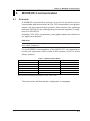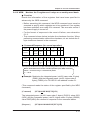
1
User’s
Manual
IM CW120C-E
CW120/121
CLAMP-ON POWER METERS
Communication Functions
IM CW120C-E
3rd Edition: May 2007 (KP)
Introduction
Introduction
This user’s manual is applicable to the CW120 (three-phase three-wire
model) and CW121 (three-phase four-wire model) clamp-on power
meters (hereinafter referred to as CW120/121) whose firmware version is
Ver. 1.06 or later, and provides information necessary for using communication functions and creating communication programs.
● The CW120/121 clamp-on power meters use the following communication protocols:
1) CW120/121-dedicated communication protocol
2) Power monitor (PR201) communication protocol
3) MODBUS communication protocol
4) PC link communication protocol
The CW120/121 cannot communicate with a higher-level device that
does not use any of the communication protocols above.
You are required to have background knowledge on the higher-level
devices to be connected to in order to understand the communication
specifications, communication hardware, language used for creating
communication programs of higher-level devices, and so on.
Note:
* PR201: Yokogawa panel-mounted power monitor
* Higher-level devices: PCs, PLCs (sequencers), graphic panels, and
others.
● For details on the functions or how to operate the CW120/121, see the
IMCW120-E user’s manual, "CW120/121 Clamp-on Power Meters."
FD No. IM CW120C-E
3rd Edition: May 2007 (KP)
All Rights Reserved. Copyright © 2002. Yokogawa Meters & Instruments Corporation
IM CW120C-E
i
Introduction
Notices
■ Regarding This User's Manual
(1) This manual should be passed on to the end user. Keep this manual
in a safe place.
(2) Read this manual carefully to gain a thorough understanding of how
to operate this product before you start using it.
(3) This manual is intended to describe the functions of this product.
Yokogawa (hereinafter simply referred to as Yokogawa) does not
guarantee that these functions are suited to the particular purpose of
the user.
(4) Under absolutely no circumstance may the contents of this manual, in
part or in whole, be transcribed or copied without permission.
(5) The contents of this manual are subject to change without prior
notice.
(6) Every effort has been made to ensure accuracy in the preparation of
this manual. Should any errors or omissions come to your attention
however, please contact your nearest Yokogawa representative or our
sales office.
■ Regarding Protection, Safety, and Prohibition Against Unauthorized
Modification
(1) In order to protect the product and the system controlled by it against
damage and ensure its safe use, make certain that all of the
instructions and precautions relating to safety contained in this
document are strictly adhered to. Yokogawa does not guarantee
safety if products are not handled according to these instructions.
(2) The following safety symbols are used on the product and/or in this
manual.
Danger! Handle with Care.
This symbol indicates that the operator must refer to an explanation in
the instruction manual in order to avoid risk of injury or death of
personnel or damage to the instrument.
Functional Grounding Terminal
This symbol indicates that the terminal must be connected to ground for
good function prior to operating the equipment.
ii
IM CW120C-E
Introduction
CAUTION
Indicates a hazard that may result in an injury to the user and/or physical damage to
the product or other equipment unless the described instruction is abided by.
NOTE
Indicates information that is essential for handling the instrument or should be noted
in order to familiarize yourself with the instrument’s operating procedures and/or
functions.
SEE ALSO
Indicates the reference location(s) for further information on the present topic.
Symbols used in figures:
[NOTE]
Draws attention to information that is essential for understanding the
operation and/or features of the product.
■ Description of Displays
(1) Some of the representations of product displays shown in this manual
may be exaggerated, simplified, or partially omitted for reasons of
convenience when explaining them.
(2) Figures and illustrations representing the controller’s displays may
differ from the real displays in regard to the position and/or indicated
characters (upper-case or lower-case, for example), to the extent that
they do not impair a correct understanding of the functions and the
proper operation and monitoring of the system.
IM CW120C-E
iii
Introduction
■ Force Majeure
(1) Yokogawa does not make any warranties regarding the product except those mentioned in the WARRANTY that is provided separately.
(2) Yokogawa assumes no liability to any party for any loss or damage,
direct or indirect, caused by the use or any unpredictable defect of the
product.
(3) Be sure to use the spare parts approved by Yokogawa when replacing parts or consumables.
(4) Modification of the product is strictly prohibited.
(5) Reverse engineering such as the disassembly or decompilation of
software is strictly prohibited.
(6) No portion of the product supplied by Yokogawa may be transferred,
exchanged, leased or sublet for use by any third party without the
prior permission of Yokogawa.
(6) Every effort has been made to ensure accuracy in the preparation of
this manual. Should any errors or omissions come to your attention
however, please contact your nearest Yokogawa representative or our
sales office.
iv
IM CW120C-E
Contents
Contents
Introduction ......................................................................................................... i
Notices
......................................................................................................... ii
Chapter 1. Communications Overview ....................................................... 1-1
1.1 Overview ............................................................................................... 1-1
1.2 Interface Specifications ......................................................................... 1-2
1.3 Setup of Communication ...................................................................... 1-3
1.3.1 Setup Procedure of Communication ............................................... 1-3
1.3.2 Wiring for Communication .............................................................. 1-3
1.3.3 Setting Communication Parameters ............................................... 1-6
Chapter 2. Communication Dedicated to CW120/121 ................................ 2-1
2.1 Overview ............................................................................................... 2-1
Chapter 3. Power Monitor (PR201) Communication .................................. 3-1
3.1 Overview ............................................................................................... 3-1
3.2 Communication Specifications .............................................................. 3-1
3.3 Commands and Responses ................................................................. 3-1
3.4 List of Commands ................................................................................. 3-3
Chapter 4. MODBUS Communication ......................................................... 4-1
4.1 Overview ............................................................................................... 4-1
4.1.1 Configuration of Messages ............................................................. 4-2
4.2 Communication with Higher-level Device ............................................. 4-2
4.2.1 List of Function Codes .................................................................... 4-3
4.3 Error Check ........................................................................................... 4-4
4.3.1 ASCII Mode .................................................................................... 4-4
4.3.2 RTU Mode ...................................................................................... 4-4
4.4 Responses from Slaves ........................................................................ 4-5
4.4.1 Responses to Normal Messages .................................................... 4-5
4.4.2 Responses to Abnormal Messages ................................................ 4-6
4.5 Commands ........................................................................................... 4-7
4.5.1 Function Code 03: Readout of D Registers .................................... 4-7
4.5.2 Function Code 06: Writing to a Single D Register .......................... 4-9
4.5.3 Function Code 08: Loop-back Test ................................................. 4-9
4.5.4 Function Code 16: Writing to Multiple Data-retaining
D Registers ................................................................................... 4-10
IM CW120C-E
v
Contents
Chapter 5. PC Link Communication ............................................................ 5-1
5.1 Overview ............................................................................................... 5-1
5.1.1 Configuration of Commands ........................................................... 5-1
5.1.2 Configuration of Response ............................................................. 5-2
5.2 Communication with Higher-level Device ............................................. 5-3
5.3 Response Error Codes ......................................................................... 5-4
5.4 List of Commands ................................................................................. 5-5
5.4.1 BRD Reads I relays on a bit-by-bit basis. .................................... 5-6
5.4.2 BWR Writes data into I relays on a bit-by-bit basis. ..................... 5-7
5.4.3 BRR Reads I relays on a bit-by-bit basis in a random order. ....... 5-8
5.4.4 BRW Writes data into I relays on a bit-by-bit basis in
a random order. .............................................................................. 5-9
5.4.5 BRS Specifies I relays to be monitored on a bit-by-bit basis. .... 5-10
5.4.6 BRM Monitors I relays on a bit-by-bit basis. .............................. 5-11
5.4.7 WRD Reads D registers and I relays on a word-by-word
basis. ............................................................................................ 5-12
5.4.8 WWR Writes data into D registers and I relays
on a word-by-word basis............................................................... 5-13
5.4.9 WRR Reads D registers and I relays on a word-by-word
basis in random order. .................................................................. 5-14
5.4.10 WRW Writes data into D registers and I relays on
a word-by-word basis in random order. ...................................... 5-15
5.4.11 WRS Specifies the D registers and I relays to be
monitored on a word-by-word basis............................................ 5-16
5.4.12 WRM Monitors the D register and I relays on
a word-by-word basis. ................................................................ 5-17
5.4.13 INF Reads the model, version, and revision information. ........ 5-18
Chapter 6. Functions and Usage of D Registers and I Relays .................. 6-1
6.1 Functions and Usage of D Registers .................................................... 6-1
6.1.1 Power Monitor PR201 Common Register Map .............................. 6-2
6.1.2 CW120/121 Dedicated Register Map ............................................ 6-5
6.2 Functions and Usage of I Relays ........................................................ 6-10
vi
IM CW120C-E
Chapter 1 Communications Overview
1.
1.1
Communications Overview
Overview
The CW120/121 has either an RS-232 serial communication interface or
RS-485 serial communication interface, through which data exchange
can be performed with a device such as a personal computer, PLC
(sequencer), or graphic panel.
Hereafter, PCs, PLCs (sequencers), and graphic panels are referred to
as “higher-level devices.”
At the time of purchase, specify the suffix code for either RS-232
communication or RS-485 communication.
Suffix Code
Model
CW120
CW121
-D, F, R, or S
-1
-2
Description
(Three-phase three-wire)
(Three-phase four-wire)
AC power cord
RS-232 communication interface
RS-485 communication interface
Table 1.1 Communication Protocols
Communication Protocol
Descriptions
CW120/121-dedicated communication
CW120/121-dedicated
communication standard
Power Monitor communication
Communication standard used for
power monitor
PC link communication with sum check
With error check
PC link communication without sum check
Without error check
MODBUS communication ASCII mode
Communication using ASCII data
MODBUS communication RTU mode
Communication using Binary data
NOTE
· Confirm the Model and Specifications.
· Attempting to save data to a PC card while performing heavy-load communication
may result in some data being lost. In such a case, decrease the baud rate. If such
a loss of data still persists, disable (off) the function for saving data to a PC card.
Then, save data, which you acquired through communication, on the upper-level
device side instead.
IM CW120C-E
1-1
Chapter 1 Communications Overview
1.2
Interface Specifications
• Specifications common to RS-232 and RS-485 communication
Synchronization:
Asynchronous
Station number:
001 to 999
Baud rate:
1200, 2400, 4800, 9600, 19200, 38400 bps
Data bits:
7 or 8 bits
Parity:
Odd, even, or none
Start bits:
Fixed to 1 bit
Stop bits:
1 or 2 bits
• Specifications specific to RS-232 communication
Electromechanical specifications: Compliant with EIA RS-232
Topology:
Point to point
Communication method: Full duplex
Connector:
Miniature DIN, 8 pins
Hardware handshake:
Whether to set CA (RTS) and CB (CTS) to
true or use then as control signals can be chosen.
Software handshake:
Transmission/reception control by X-on
and X-off signals is possible.
X-on (ASCII 11H)
X-off (ASCII 13H)
Error detection:
Set by communication protocol
Reception buffer length: 1024 bytes
• Specifications specific to RS-485 communication
Electromechanical specifications: Compliant with EIA RS-485
Topology:
Multidrop
Communication method: Half duplex
Connector:
4 screw terminals (M3)
Hardware handshake:
Not available
Software handshake:
Not available
Error detection:
Set by communication protocol
Reception buffer length: 1024 bytes
Maximum transmission distance:
1.2 km (when using shielded
cable containing 2 twisted pairs of AWG
24 conductors)
Terminating resistor:
Approx. 120 Ω built-in
1-2
IM CW120C-E
Chapter 1 Communications Overview
1.3
Setup of Communication
This chapter describes the procedure to set up the communication
functions and also refers to some notes on wiring and communication
parameters.
1.3.1
Setup Procedure of Communication
Set up the communication functions of the CW120/121 as follows:
Connect a higher-level device and a CW120/121.
(See
section
1.3.2.)
Set up the communication parameters of the CW120/121.
(See
section
1.3.3.)
Create communication programs for the higher-level device to perform communication.
* Create communication programs referring to the documentation of each higher-level device.
* In this manual, higher-level devices generically denotes PCs, PLCs (sequencers),
and graphic panels.
1.3.2
Wiring for Communication
Connect the CW120/121 controller and the higher-level device for
communication. The wiring procedures and precautionary notes are as
follows.
CAUTION
To avoid an electrical shock, be sure to turn off the power supply source to the
equipment involved before you start wiring.
Before you start wiring, read the user's manual of each device.
IM CW120C-E
1-3
Chapter 1 Communications Overview
● Wiring for RS-485 Communication
(1) Wiring to a Personal Computer
Since general personal computers cannot directly be connected to the
RS-485 interface, wiring must be provided via an RS-232/RS-485
converter. The following figures show the wiring for 2-wire connection.
● 2-wire connection
ML1Terminating
resistor
220Ω1/4W
PC
CW120/121
CW120/121
B(+)
14(+)
A(-)
13(-)
(TM)
SG
The built-in
terminating resistor
(approx. 120 Ω 1/4W)
is enabled by
shortcircuiting these
terminals.
(SG)
RS-232
straight cable
Communication cable
JIS Class 3 grounding
(grounding resistance
of 100Ω or less)
JIS Class 3 grounding
(grounding resistance
of 100Ω or less)
Communication cable
JIS Class 3 grounding
(grounding resistance
of 100Ω or less)
Maximum number of units connectable: 31 (except for ML1Maximum distance: 1.2 km
)
[NOTE] ML1- is the converter of Yokogawa M&C Corporation. You can also
use other RS-232/RS-485 converters. Before you use another converter,
check its electrical specifications.
CAUTION
Do not share the grounding wire with another controller. Doing so may result in a
failure of the controller.
Use crimp terminals at the cable ends.
1-4
IM CW120C-E
Chapter 1 Communications Overview
(2) Wiring to a PLC (Sequencer) or Graphic Panel
Since general PLCs (sequencers) and graphic panels have an RS-485
interface, they can be directly connected to a CW120/121. If your PLC
(sequencer) or graphic panel has an RS-232 interface, see subsection
(1) .
PLC or graphic panel
FAM3
Terminating
resistor
220Ω1/4W
CW120/121
CW120/121
B(+)
14(+)
A(-)
13(-)
(TM)
The built-in
terminating resistor
(approx. 120 Ω 1/4W)
is enabled by
shortcircuiting these
terminals.
(SG)
SG
Communication cable
JIS Class 3 grounding (grounding
resistance of 100Ω or less)
Communication cable
JIS Class 3 grounding (grounding
resistance of 100Ω or less)
Maximum number of units connectable: 31
(except for PLC or graphic panel)
Maximum distance: 1.2 km
[NOTE] In the case of MELSEC (Mitsubishi Electric Corporation´s sequencer),
“B” is for (–), and “A” is for (+). In the case of Graphic panel (Digital
Corporation´s), RS232/RS485 converter is needed.
CAUTION
Do not share the grounding wire with another controller. Doing so may result in a
failure of the controller.
Use crimp terminals at the cable ends.
● Wiring for RS-232 Communication
Wire the CW120/121 to a general personal computer as shown below.
Personal Compute
CW120/CW121
Communication cable
Note: Use the following communication cable.
Cable
RS-232 communication cable for PC
IM CW120C-E
Connectors
Part number
9 pins
91011
25 pins
91009
1-5
Chapter 1 Communications Overview
1.3.3
Setting Communication Parameters
This section describes the communication parameters and setting ranges
necessary to use the communication functions.
(1) Setting Communication Protocols
Follow the procedure below to set the communication protocol supported
by the higher-level device.
<Procedure>
1) When the measurement screen of the CW120/121 is displayed, press
the MEAS/SET key to call the setting item selection screen.
2) Press either the key or key until "
" is displayed in the
upper part of the LCD.
3) Press the ENTER key and verify that the lower row on the LCD
flashes.
4) Press either the key or key to select the appropriate
communication protocol as shown in the figure below.
5) Press the ENTER key to confirm the selection and return to the
setting item selection screen. Press the ESC key to cancel a selection
and return to the setting item selection screen.
6) Press the MEAS/SET key to return to the measurement screen.
Setting item
selection screen
CW120/CW121
communication
MODBUS communication
(RTU mode)
1-6
Power Monitor
communication
PC link communication
without check sum
MODBUS communication
(ASCII mode)
PC link communication
with check sum
IM CW120C-E
Chapter 1 Communications Overview
(2) Setting Station Number
Follow the procedure below to set the device number (station number) of
the CW120/121 within the device number limits (Table 1.2) specific to
each communication protocol.
Table 1.2 Communication protocols and device number limits
Communication protocol
Device number limits
CW120/121
Power monitor (PR201) communication
1 to 999
1 to 31
PC link communication without checksum
1 to 99
PC link communication with checksum
MODBUS communication (ASCII mode)
MODBUS communication (RTU mode)
1 to 99
1 to 247
1 to 247
<Procedure>
1) When the measurement screen of the CW120/121 is displayed, press
the MEAS/SET key to call the setting item selection screen.
2) Press either the key or key until the "NO." mark is displayed in
the lower part of the LCD and the current setting for the device
number is displayed in the upper row.
3) Press the ENTER key and verify that the least significant digit in the
upper row on the LCD flashes.
4) Press either the key or key to select a digit and change its value
by pressing either the key or key.
5) When you have finished setting the number, press the ENTER key to
confirm the setting and return to the setting item selection screen.
Press the ESC key to cancel a setting and return to the setting item
selection screen.
6) Press the MEAS/SET key to return to the measurement screen.
Setting item
selection screen
Least significant digit
Tens digit
Most significant digit
[NOTE] When connecting more than one device using RS-485 communication, be sure to
use a unique device number for each device.
IM CW120C-E
1-7
Chapter 1 Communications Overview
(3) Setting Communication Interface Parameters
Follow the procedure below to set the communication interface parameters. Set the same communication interface parameters for the CW120/
121 as those set for the higher-level device.
<Procedure>
1) When the measurement screen of the CW120/121 is displayed, press
the MEAS/SET key to call the setting item selection screen.
2) Press either the key or key until the "COM" mark is displayed in
the lower part of the LCD, the current settings for the baud rate is
displayed on the top row and the current settings for data length,
parity, and stop bits are displayed in the lower row.
3) Press the ENTER key and verify that the baud rate in the upper row
on the LCD flashes.
4) Press either the key or key to select the baud rate.
5) Press the key and verify that the rightmost number for the data
length flashes.
6) Press either the key or key to select the data length.
7) Press the key and verify that the character in the middle for the
parity flashes.
8) Press either the key or key to select the parity.
9) Press the key and verify that the number for the stop bits flashes.
10) Press either the key or key to select the stop bits.
11) When you have finished making all the settings, press the ENTER
key to confirm them and return to the setting item selection screen.
Press the ESC key to cancel the settings and return to the setting
item selection screen.
12) Press the MEAS/SET key to return to the measurement screen.
Setting item
selection screen
Baud rate
Data length
Stop bits
Parity
: None
: Even
: Odd
SEE ALSO
Chapter 7 of the IM CW120-E user's manual for details on how to make settings.
1-8
IM CW120C-E
Chapter 2 Communication Dedicated to CW120/121
2.
2.1
Communication Dedicated to CW120/121
Overview
Communication dedicated to CW120/121 allows a variety of
measurement values to be read by a higher-level device and the CW120/
121 to be configured from a higher-level device. The communication
protocol used is different than that used during RS-232 or RS-485
communication. For details, see the appendix of IMCW120-E,
"Communication Commands."
IM CW120C-E
2-1
Chapter 3 Power Monitor (PR201) Communication
3.
3.1
Power Monitor (PR201) Communication
Overview
Using the command/response method, you can read a variety of measured values onto your personal computer. Readout can be achieved in
two ways: reading measured values one by one or reading the values at
one time (those of measurement data items assigned in the selected
parameter).
3.2
Communication Specifications
Station number: 1 to 31
Communication error handling:
The CW120/121 discards a received command and returns no response if the command is invalid (ignores
electrical noise and faulty commands). Any time-out process therefore should be run at the higher-level personal
computer. Set the time-out option to a value no smaller
than one second. The CW120/121 returns an error response if the parameter or data is erroneous.
3.3
Commands and Responses
Command elements:
1 byte
2 bytes
1 byte
STX
Command
Parameter
2 bytes
Station
number
Variable-length
2 bytes
1 byte
1 byte
Data
Check sum
ETX
CR
Range of sum check
STX:
Command:
Parameter:
Station number:
Data:
Check sum:
ETX:
CR:
IM CW120C-E
Start of Text (hexadecimal: 02)
2-byte ASCII code (DG or DP)
1-byte ASCII code (0 to X)
2-byte ASCII code (01 to 1F)
Not provided at the time of data readout; provided as
variable-length ASCII code at the time of setpoint change
(byte size depends on the type of parameter)
2-byte ASCII code (00 to FF) representing a value obtained by summing the data within the range of sum
check in a hexadecimal way and then converting the
least significant two digits to an ASCII code
End of Text (hexadecimal: 03)
Carriage Return (hexadecimal: 0D)
3-1
Chapter 3 Power Monitor (PR201) Communication
Response elements:
1 byte
2 bytes
1 byte
STX
Response
Parameter
2 bytes
Station
number
Variable-length
2 bytes
1 byte
1 byte
Data
Check sum
ETX
CR
Range of sum check
STX:
Response:
Parameter:
Station number:
Data:
Check sum:
ETX:
CR:
3-2
Start of Text (hexadecimal: 02)
2-byte ASCII code (DG or DP)
1-byte ASCII code (0 to Z)
2-byte ASCII code (01 to 1F)
Variable-length ASCII code (byte size depends on the
type of parameter)
2-byte ASCII code (00 to FF) representing a value obtained by summing the data within the range of sum
check in a hexadecimal way and then converting the
least significant two digits to an ASCII code
End of Text (hexadecimal: 03)
Carriage Return (hexadecimal: 0D)
IM CW120C-E
Chapter 3 Power Monitor (PR201) Communication
3.4
List of Commands
Table 3.1 Command:DG (1/3)
Parameter
0
1
2
3
Descriptions
Measured
value read-out
in block
Active electric
energy read-out
Optional
active electric
energy
read-out
Instantaneous
active power
value
Power
monitor
adaptable
models
No optional
measuring
Power factor
measuring
Current 2
measuring
Preceding
value
Present
value
4
Power monitor
response data
format
40 bytes
Data of parameters 1 to 5
and 6 (power factor measuring)
Data of parameters 1 to 5
and 6 (current 2 measuring)
00000 to
99999 [kWh]
00000 to
99999 [Wh]
00000 to
99999 [Wh]
0.001E+2 to
. E+O
9.999E+6 [W]
46 bytes
Optional
instantaneous
value
8
9
A
Optional
integration start
Optional
integration stop
Maximum/minimum values
initialization
Measured and
maximum/minimum values
read-out in block
10 bytes
00000 [Wh]
9 bytes
0.000E+0 to
9.999E+9 [W]
"----" 0
"Or" Voltage range:
150 V, 300 V
Rated power range
× 1.69
Voltage range:
450 V
Rated power range:
× 1.43
0.000E+0 to
9.999E+9 [V]
"----" 0
"Or" Voltage range:
150 V, 300 V
Rated voltage range
× 1.3
Voltage range:
450 V
Rated voltage range:
× 1.1
0.000E+0 to
9.999E+9 [A]
"----" 0
"Or" Rated current range:
× 1.3
0.001E+2 to
9.999E+6 [A]
8 bytes
Current 2
measuring
. E+O
No optional
measuring
Power factor
measuring
Current 2
measuring
10 bytes
. E+O
. Transfer of data of
parameters 1 to 6
00000 to
99999 [kWh]
00000 [kWh]
8 bytes
No data
7
5 bytes
0.001E+2 to
9.999E+6 [V]
No optional
measuring
Power factor
measuring
CW120/121
response data
48 bytes
. E+O
Current 1
instantaneous
value
6
Response
data size
Data of parameters 1 to 5
Voltage 1
instantaneous
value
5
Power
monitor
response
data range
0 byte
D0. 500 to
1.000 to
G0. 500
0.001E+0 to
9.999E+6 [A]
6 bytes
D0.500 to 1.000 to G0.500
"----" 0
"Or"
8 bytes
No data
0 byte
No data
No data
0 byte
No data
No data
0 byte
No data
Data of parameters 1 to 5 and B to D
64 bytes
Data of parameters 1 to 6 and B to D
70 bytes
Data of parameters 1 to 6 and B to D
72 bytes
Data of parameters 1 to 6
and B to D transferred
"Or": The input value is over the range.
"----": Measurement not possible because input value is out of measurement range.
IM CW120C-E
3-3
Chapter 3 Power Monitor (PR201) Communication
Table 3.1 Command:DG (2/3)
Parameter
Descriptions
Power
monitor
adaptable
models
Power monitor
response data
format
Power
monitor
response
data range
Response
data size
CW120/121
response data
. E+O
0.001E+2 to
9.999E+6 [V]
8 bytes
0.000E+0 [V]
. E+O
0.001E+2 to
9.999E+6 [V]
8 bytes
0.000E+0 [V]
. E+O
0.001E+0 to
9.999E+6 [A]
8 bytes
0.000E+0 [V]
No data
0 byte
No data
. E+O
8 bytes
Data of parameters G, 2, 3, 4, H, J, 5, K,
and L
Data of parameters G, 2, 3, 4, H, J, 5, K,
and L, and 6 (power factor measuring)
75 bytes
Active electric
energy read-out
Voltage 2
instantaneous
value
E+O
00000E+3 to
99999E+6 [Wh]
0.001E+2 to
9.999E+6 [V]
8 bytes
8 bytes
0.000E+0 to 9.999E+9 [V]
"----" 0
"0r"
Voltage range:
150 V, 300 V
Rated voltage range
× 1.3
Voltage range:
450 V
Rated power range:
× 1.1
Voltage 3
instantaneous
value
. E+O
0.001E+2 to
9.999E+6 [V]
8 bytes
K
Current 2
instantaneous
value
. E+O
0.001E+0 to
9.999E+6 [A]
8 bytes
L
Current 3
instantaneous
value
. E+O
0.000E+0 to 9.999E+9 [V]
"---" 0
"Or" Voltage range: 1
50 V, 300 V
Rated voltage range
× 1.3
Voltage range:
450 V
Rated power range:
× 1.1
0.000E+0 to 9.999E+9 [A]
"---" 0
"Or" Rated current range
× 1.3
0.000E+0 to 9.999E+9 [A]
"---" 0
"Or" Rated current range
× 1.3
M
Measured and
maximum/mini
mum values
read-out in block
B
C
D
E
F
G
H
I
J
Voltage 1
maximum value
read-out
Voltage 1
minimum value
read-out
Current 1
maximum value
read-out
Current 2
maximum value
read-out
Measured
values read-out
in block
No current 2
measuring
Current 2
measuring
No optional
measuring
Power factor
measuring
. E+O
81 bytes
8 bytes
No optional
measuring
Power factor
measuring
3-4
Data of
parameters G, 2,
3, 4, H, J, 5, K, L,
and B, C, D, and
N to T
Data of
parameters G, 2,
3, 4, H, J, 5, K,
and L, and 6
(power factor
measuring),
and B, C, D, and
N to T
Data of parameters G, 2, 3, 4,
H, J, 5, K, and L, and 6 (power
factor measuring) transferred
00000E+3 to 9999E+6 [Wh]
123 bytes
129 bytes
Data of parameters G, 2, 3, 4,
H, J, 5, K, L, and 6
(power factor measuring), and
B, C, D, and N to T
IM CW120C-E
Chapter 3 Power Monitor (PR201) Communication
Table 3.1 Command:DG (3/3)
Parameter
N
O
P
Q
R
S
T
U
V
W
X
Y
Z
Descriptions
Voltage 2
maximum value
read-out
Voltage 3
maximum value
read-out
Voltage 2
minimum value
read-out
Voltage 3
minimum value
read-out
Current 2
maximum value
read-out
Current 3
maximum value
read-out
Power
monitor
adaptable
models
Power monitor
response data
format
. E+O
. E+O
. E+O
Power
monitor
response
data range
0.001E+2 to
9.999E+6 [V]
0.001E+2 to
9.999E+6 [V]
Response
data size
CW120/121
response data
8 bytes
0.000E+0 [V]
8 bytes
8 bytes
0.000E+0 [V]
. E+O
0.001E+2 to
9.999E+6 [V]
8 bytes
0.000E+0 [V]
. E+O
0.001E+2 to
9.999E+6 [V]
8 bytes
0.000E+0 [V]
. E+O
0.001E+2 to
9.999E+6 [A]
8 bytes
0.000E+0 [A]
. E+O
0.001E+2 to
9.999E+6 [A]
8 bytes
0.000E+0 [A]
Model and
suffix code
read-out
PR201--
14 bytes
Single-phase two-wire:
PR201-11011-20
Single-phase three-wire:
PR201-21011-20
Three-phase three-wire:
PR201-31011-20
Three-phase four-wire:
PR201-41011-20
Single-phase two-wire2
PR201-11011-20
Single-phase two-wire3
PR201-11011-20
Error response
2 bytes
00: Not error
80: Check sum error
"Or": The input value is over the range.
"----": Measurement not possible because input value is out of measurement range.
IM CW120C-E
3-5
Chapter 3 Power Monitor (PR201) Communication
Table 3.2 Command:DP
Para- Descriptions
meters
Power
monitor
adaptable
models
Power monitor
command data
format
Power
monitor
command data
range
Command
data size
CW120/121
response data
Set value
read-out
No data (response *1)
0 byte
VT ratio, CT ratio, Integrated
low-cut power (value: 0)
1
2
3
4
VT ratio setting
00001 to 32000
5 bytes
5
CT ratio setting
00.05 to 32000
5 bytes
00001 to 10000
During setup, resets electric
energy read-out and elapsed
time.
If integration is in progress,
stops integration and resets.
Then resumes integration.
00001 to 10000
During setup, resets electric
energy read-out and elapsed
time.
If integration is in progress,
stops integration and resets.
Then resumes integration.
Remote reset
Integrated
low-cut power
Integrated pulse
unit
ON pulse width
of integrated
pulse
No data
. 00.1 to 99.9
0 byte
4 byte
No processing carried out
No processing carried out
8 bytes
No processing carried out
6.667E-6 to
1.000E-1
0010 to 1270
4 byte
No processing carried out
E
Input scaling
"L" level setting
for analog output
(:+or-)
-4800 to +4800
5 bytes
No processing carried out
F
Input scaling "H"
level setting for
analog output
(:+or-)
-4800 to +4800
5 bytes
No processing carried out
G
Electric energy
reset
No data (buffer data is reset, too)
0 byte
Resets electric energy readout and elapsed time.
If integration is in progress,
stops integration and resets.
Then resumes integration.
0
6
7
8
9
A
B
C
D
. E-O
*1: The response for set value read-out command is as follows:
VT ratio, CT ratio, and integrated low-cut power: 16 bytes
3-6
IM CW120C-E
Chapter 4 MODBUS Communication
4.
4.1
MODBUS Communication
Overview
A MODBUS communication protocol is one of the protocols used to
communicate with devices such as PCs, PLCs (sequencers), and graphic
panels. Via this communication protocol, these devices can exchange
data with CW120/121 by reading/writing the internal registers (D registers) of a CW120/121.
Hereafter, PCs, PLCs (sequencers), and graphic panels are referred to
as “higher-level devices.”
SEE ALSO
As to configuration of inner registers, refer to "Function and usage of D register
and I relay" (Chapter 6).
For the MODBUS communication of the CW120/121, two transmission
modes are supported: ASCII mode (ASCII system) and RTU mode
(binary system).
Table 4.1 ASCII and RTU Modes
Item
ASCII mode
RTU mode
Number of data bits
7 bits (ASCII), 8 bits (ASCII)
8 bits (binary)
Message start mark
: (colon)
Unnecessary
Message end mark
CR + LF
Unnecessary
Message length (Note 1)
2N + 1
N
Data time intervals
1 second or less
24-bit time or less (Note 2)
Error detection
Longitudinal redundancy check: LRC
Cyclic redundancy check: CRC-16
Note 1: When the message length in the RTU mode is assumed to be N.
Note 2: When the communication rate is 9600 bps, 1‚ 9600 · 24 sec. or less.
The next section will discuss the configuration of messages.
IM CW120C-E
4-1
Chapter 4 MODBUS Communication
4.1.1
Configuration of Messages
Messages sent from a higher-level device to a CW120/121 consist of the
following elements.
Element
Start of
Message
Mark
Address
Number
(ADR)
Function
Code
Data
Error
Check
Number of bytes in ASCII mode
1
1
1
4n
2
2
Number of bytes in RTU mode
None
2
2
2n
2
None
(1)
(2)
(3)
(4)
(5)
(6)
Mode
End of
Message
Mark
(1) Start of Message Mark
This mark indicates the start of a message. Note that only ASCII mode
requires a colon.
(2) Address Number (1 to 247)
An address number is used by a higher-level device to identify which
CW120/121 to communicate with. (ID number of CW120/ CW121)
(3) Function Code (See subsection 4.2.1, “List of Function Codes”)
The function code specifies a command (function code) from the higherlevel device.
(4) Data
This element specifies D register numbers, the number of D registers,
parameter values, and so on in accordance with the function code.
(5) Error Check
In ASCII mode carried out by the longitudinal redundancy check (LRC)
system.
In RTU mode carried out by the cyclic redundancy check (CRC-16)
system.
(6) End of Message Mark
This mark indicates the end of a message.
Note that only ASCII mode requires CR and LF.
4.2
Communication with Higher-level Device
When you use a commercially available SCADA or the like or a usercreated communication program, you must be careful when specifying D
register numbers contained in messages because in both cases, you
cannot use the original D register numbers as they are.
4-2
IM CW120C-E
Chapter 4 MODBUS Communication
● To specify D registers
(1) When using a commercially available SCADA or the like, specify D
register numbers by changing them into reference numbers. To change
them into a reference number, replace the D register number's leading
character “D” with “4”. (When using a DDE server or others, specify
these reference
numbers.)
(2) In a user-created communication program, specify a D register using
the hexadecimal number of the value obtained by subtracting “40001”
from the D register's reference number. (Specify this hexadecimal
number.)
Example: To specify “D0101”
• For a message using commercially available SCADA or the like,
specify reference number “40101.”
• For a message in a user-created communication program, specify
“0064”, the hexadecimal number of “0100”, which is obtained by
subtracting 40001 from the reference number.
NOTE
In RTU mode, there may be a case when communication cannot be carried out with
an upper-level device that detects frame delimiters at high speed. In such a case,
decrease the baud rate.
4.2.1
List of Function Codes
Function codes are command words used by the higher-level device to
obtain the D register information of CW120/121.
Table 4.2 Function Codes
Code
03
Function
Reads data from multiple D
registers.
06
Description
Capable of reading data from a maximum of 32 successive registers
from D0001 to D0576.
Capable of writing data to one register from D0001 to D0576.
08
Writes data into D register.
Capable of checking singnal transmission.
16
Performs loop back test.
Writes data into multiple D
registers.
Capable of writing data into a maximum of 32 successive registers
from D0001 to D0576.
• The write function codes will not write into read-only or disabled D
registers.
IM CW120C-E
4-3
Chapter 4 MODBUS Communication
4.3
Error Check
MODBUS communication has two modes: ASCII mode which is ASCIItext communication and RTU mode which is binary communication.
These two modes use different error check methods.
4.3.1
ASCII Mode
In ASCII mode, an error check is run using the LRC method, i.e., logical
redundancy check. This mode calculates the LRC value from the same
data as that of the RTU mode. That is, all blocks of a message, from the
slave address to the last data item, except the colon (:), carriage return
(CR) and line feed (LF), are converted one byte hexadecimal data and
summed on a byte-by-byte basis. A two’s complement taken from least
sigfinicant two bytes of the value thus obtained equals the LRC value. At
this point, ignore any carry into the most significant digit occurring during
the summing.
Example:
Calculating the LRC value when the message is
[:]303530333030363430303032[LRC][CR][LF]
[1]
Change the underlined ASCII data to one-byte hex data.
→05, 03, 00, 64, 00, 02
[2]
Sum up this one-byte hex data on a byte-by-byte basis.
→05 + 03 + 00 + 64 + 00 + 02 = 6E
[3]
Take the two’s complement of the least significant one byte of
the data thus summed up.
→92
4.3.2
RTU Mode
In RTU mode, an error check is run using the CRC-16 method, i.e.,
cyclic redundancy check. In this method, all blocks of a message, from
the slave address to the last data item, are concatenated in series and
the value thus obtained is divided by a predetermined 17-bit binary
number. The resulting 16-bit remainder then equals the CRC-16 value.
Note that data subjected to computation is only the value given by the 8bit block of the message and does not include the start bit, stop bit, and
parity bit.
4-4
IM CW120C-E
Chapter 4 MODBUS Communication
4.4
Responses from Slaves
A CW120/121 receives a command message from the higher-level
device. If the received command message is found to be normal and
directed at the slave address of the CW120/121 itself, the CW120/121
concludes the content of the message to be normal. Thus, the CW120/
121 enters the phase of executing message processing, deciphers the
content of the command message, and processes with the message.
The CW120/121 does not execute message processing, however, if the
received command message is found to be abnormal. In that case, the
CW120/121 either ignores the received message or creates a response
message telling the received message is erroneous.
After receiving a normal command message and executing a given
process, the CW120/121 creates and sends a response message to
which error check data appropriate for the command function code of the
higher-level device is added.
4.4.1
Responses to Normal Messages
For a loop back function or a function for writing to a single register, the
CW120/121 returns the received command message as a response
message.
For a function for writing to multiple registers, the CW120/121 returns
part of the received command message as the response message.
For a readout function, the CW120/121 adds the read data to the ends of
the address number and function code of the received command
message, and returns the message as the response message.
IM CW120C-E
4-5
Chapter 4 MODBUS Communication
4.4.2
Responses to Abnormal Messages
If there is any failure other than transmission errors, the CW120/CW121
returns the following response message without executing any process:
Address number
Function code + 80H
Error code
Error check data
The following table summarizes details on the error codes.
Error code
Description
01
Function code error (nonexistent error code)
02
Abnormal register number
03
Abnormal number of registers
The CW120/121 does not regard it as an error even if there is any
unused register among those with consecutive register numbers specified
by a read-out function; rather, the CW120/121 returns a value of 0 in this
case.
The CW120/121 returns the error code 02 if the first of specified
consecutive addresses is made to fall outside the given range by the
number of registers specified, even though it was initially within the
range.
4-6
IM CW120C-E
Chapter 4 MODBUS Communication
4.5
Commands
4.5.1
Function Code 03: Readout of D Registers
In the example shown here, the function reads four consecutive registers
starting from the register D0043 of the slave with the slave address 17.
Take special note of the fact that the Starting D Register Number field is
set to “42”.
Table 4.3 Message Sent from Mater
Element
Contents
HEX
Start-of-message mark
Address
17
11
03 (=function code)
03
03
Starting D register number
(higher-order)
00
Example for RTU Mode
(24-bit time)
31h
31h
30h
33h
0001 0001
30h
0000 0000
0000 0011
30h
42
Starting D register number
(lower-order)
Example for ASCII mode
(Reference only)
3Ah (: colon)
2A
32h
0010 1010
41h
Number of D register
(higher-order)
00
0000 0000
30h
4 registers
Number of D register
(lower-order)
30h
04
30h
0000 0100
34h
0110 0111
42h
Error check data
=BEh
45h
End-of-message mark
IM CW120C-E
0Dh(=[CR])
0Ah(=[LF])
=6751h
0101 0001
None
4-7
Chapter 4 MODBUS Communication
Table 4.4 Message Sent from Slave
Contents
Element
HEX
Start-of-message mark
Address
17
11
03 (= function code)
03
03
Example for ASCII Mode
(Reference only)
Example for RTU Mode
(Reference only)
3Ah (: colon)
(24-bit time)
31h
31h
30h
33h
Byte count
8 bytes
30h
08
38h
Higher
-order
33h
3F
46h
3F80
Lower
-order
80
Higher
-order
00
38h
30h
30h
30h
0000
Byte count for D
register status
(= number of
registers32)
Lower
-order
00
Higher
-order
3F
30h
30h
80
Higher
-order
00
Error check data
0000 1000
0011 1111
1000 0000
0000 0000
0000 0000
0011 1111
46h
38h
30h
1000 0000
30h
30h
0000
Lower
-order
0000 0011
33h
3F80
Lower
-order
0001 0001
0000 0000
30h
00
30h
36h
36h
=66h
0000 0000
0000 1110
0111 0111
=0E77h
0Dh (=[CR])
End-of-message mark
0Ah (=[LF])
None
* The D register numbers (addresses) are specified using relative addresses.
* The maximum number of D registers that are read is 32.
4-8
IM CW120C-E
Chapter 4 MODBUS Communication
4.5.2
Function Code 06: Writing to a Single D Register
Table 4.5 Message Sent from Master
Start-of-message mark
Address
06 (= function code)
D register number (higher-order)
D register number (lower-order)
Data to write (higher-order)
Data to write (lower-order)
Error check data
End-of-message mark
* Data to write: Optional.
* Specify D register numbers (addresses)
using relative addresses.
Response from Slave
The slave returns the received command message as a response
message.
4.5.3
Function Code 08: Loop-back Test
A loop-back test is used to check signal transmission.
Table 4.6 Message Sent from Higher-level Device
Start-of-message mark
Address
08 (= function code)
Diagnostic code (higher-order) fixed to 00
Diagnostic code (lower-order) fixed to 00
Data (higher-order)
Data (lower-order)
Error check data
End-of-message mark
Table 4.7 Diagnostic Codes
Diagnostic Code
00 00
IM CW120C-E
Meaning
Command message return
Data
Arbitrary
4-9
Chapter 4 MODBUS Communication
Table 4.8 Message Sent from CW120/121
Start-of-message mark
Address
08 (= function code)
Diagnostic code (higher-order) fixed to 00
Diagnostic code (lower-order) fixed to 00
Data (higher-order)
Data (lower-order)
Error check data
End-of-message mark
Data: Varies depending on the diagnostic
code sent from higher-level device.
4.5.4
Function Code 16: Writing to Multiple Data-retaining D Registers
This function enables you to change the states of D registers with
consecutive addresses.
Table 4.9 Message Sent from Higher-level Device
Start-of-message mark
Address
10 (= function code)
Starting D register number (higher-order)
Starting D register number (lower-order)
Number of registers (higher-order)
Number of registers (lower-order)
Byte count
Data (higher-order)
Data (lower-order)
Error check data
End-of-message mark
Table 4.10 Message Sent from CW120/121
Start-of-message mark
Address
10 (=function code)
Starting D register number (higher-order)
Starting D register number (lower-order)
Number of registers (higher-order)
Number of registers (lower-order)
Error check data
End-of-message mark
* The maximum number of D registers to
which data are written is 32.
4-10
IM CW120C-E
Chapter 5 PC Link Communication
5.
5.1
PC Link Communication
Overview
PC link communication protocol is one of the protocols used to communicate with devices such as PCs, PLCs (sequencers), and graphic
panels. Via this communication protocol, these devices can exchange
data with a CW120/121 by reading/writing the controller’s internal
registers (D registers and I relays).
Hereafter, PCs, PLCs (sequencers), and graphic panels shall be referred
to as “higher-level devices.”
SEE ALSO
As to configuration of inner registers, refer to "Function and usage of D register
and I relay" (Chapter 6).
The next section will discuss the configuration of commands and responses.
5.1.1
Configuration of Commands
Commands sent from a higher-level device to a CW120/121 consist of
the following elements.
Number of bytes
Element
1
2
2
1
3
Variable length
Address number CPU number Time to wait
Data corresponding
STX (Station number)
for response Command
01
to command
0
(1)
(2)
(3)
(4)
(5)
(6)
2
Check sum
(7)
1
1
ETX CR
(8)
(9)
(1) STX (Start of Text)
This control code indicates the start of a command. The character code
is CHR$(2).
(2) Address Number (01 to 31)
Address numbers are used by a higher-level device to identify which
CW120/121 to communicate with. (ID number of the CW120/121)
(3) CPU Number
This number is fixed to 01.
(4) Time to Wait for Response
This is fixed to 0.
(5) Command (See subsection 5.4)
Specify a command to be issued from the higher-level device.
IM CW120C-E
5-1
Chapter 5 PC Link Communication
(6) Data Corresponding to Command
Specify an internal register (D register or I relay), number of data items,
parameter of CW120/121 values, or others.
(7) Check sum
In PC link communication with sum check, the ASCII codes of the text
between STX and the checksum are converted into hexadecimal values
and added on a byte basis. Then the lowermost byte of the added results
is turned into ASCII code, and its lower byte is used as the checksum.
This 2-byte space is unnecessary for PC link communication without sum
check.
(8) ETX (End of Text)
This control code indicates the end of a command string. The character
code is CHR$(3).
(9) CR (Carriage Return)
This control code marks the end of a command. The character code is
CHR$(13).
NOTE
The control codes STX, ETX, and CR in commands are indispensable. Do not miss
any of them when you create a communication program for PC link communication.
A communication failure will result if any of them are omitted or if the order is
incorrect.
5.1.2
Configuration of Response
Responses from a CW120/121 with respect to a command sent from the
higher-level device consist of the elements shown below, which differ
depending on the condition of communication − normal or failure.
1) With Normal Communication
When communication is carried out normally, the CW120/121 returns the
character string “OK” and, in response to read commands, also returns
read-out data.
Number of bytes
1
2
2
2
Variable length
2
Element
STX
Address number
CPU number:
01
OK
Parameter data
Checksum
(Station number)
1
1
ETX CR
2) In the Event of Failure
If communication is carried out abnormally, the CW120/121 returns the
character string “ER” and error codes (EC1 and EC2). (See subsection
5.3, Response Error Codes.)
5-2
IM CW120C-E
Chapter 5 PC Link Communication
• No response is made in case of an error in address number
specification or CPU number specification.
• If a CW120/121 cannot receive an ETX contained in a command, a
response may not be made.
* As a measure against these situations, provide a timeout processing in
the communication functions or communication programs of the
higher-level device.
Number of bytes
Element
5.2
1
2
STX Address number
(Station number)
2
2
2
(2)
3
2
CPU number:
01
ER
EC1
(EC2)
Command
Checksum
1
1
ETX CR
Communication with Higher-level Device
In PC link communication, when specifying D registers or I relays
(internal registers of CW120/121), you can use the numbers as is. The
numbers of these internal registers are in the following format:
• D register: Dxxxx (xxxx is D register number.)
• I relay: Ixxxx (xxxx is I relay number.)
Higher-level devices to be connected to a CW120/121 are those capable
of handling the PC link communication protocol.
Communication with FA-M3 with UT-link module
No ladder communication program is required to communicate with FAM3 with UT-link module (Yokogawa PLC). The UT-link module’s function
offers 3 modes, in which users can exchange data without paying
attention to the communication procedure. (For more information, see the
user's manual of UT-link module “IM 34M6H25-01E.”)
●Non-user-specifiable mode: Always reads the predetermined devices*
of the CW120/121 (users cannot specify
devices).
• Predetermined devices* of CW120/121: D0001 to D0022
(Since these devices* are in the read only area of CW120/121, they
cannot be written to.)
●User-specifiable mode: ...... Always reads/writes the user-specified
devices* of the CW120/121.
●Command mode: ............... Accesses the devices* of the CW120/121
only when necessary.
*: “Predetermined device” or “device” here denotes the internal
registers of the CW120/121 (D registers and I relays).
IM CW120C-E
5-3
Chapter 5 PC Link Communication
5.3
Response Error Codes
The error codes (EC1) and detailed error codes (EC2) of response are
as follows.
EC2 is no-meaning when error code (EC1) is not included in following
table 5.2.
Table 5.1 Error Codes (EC1)
Error code
Meaning
Causes
02
Command error
The command does not exist.
Command not executable
03
Internal register
specification error
Specified register number does not exist.
In handling bit registers (I relays) on a word-by-word
basis, its specification is not correct.
04
Out of setting range
A character other than 0 and 1 was used for bit setting.
A value other than 0000 to FFFF was specified in the
word specification.
The start address specified for data loading/saving is
out of the address range.
05
Data number error
Specified number of bits or words is too large.
The number of data or registers specified and the
number of parameters for them are inconsistent.
06
Monitor error
An attempt was made to execute monitoring without
specifying any device to be monitored (BRS or WRS).
08
Parameter error
Wrong parameter.
42
Sum error
The sum does not match.
43
Internal buffer overflow
Too much data was received.
44
Timeout between received
characters
No terminal character or ETX is received.
Table 5.2 Detailed Error Codes (EC2)
Error code
(EC1)
5-4
Meaning
03
Internal register
specification error
04
Out of setting range
05
Data number error
08
Parameter error
Detailed error code (EC2)
Indicates the parameter number where an error occurred.
This is the number of a parameter in sequence that first
resulted in an error when counted from the leading
parameter.
Example:
Error in internal register
specification
↓
STX 01010WRW 02 D0043, 3F80, A0044, 0000
Parameter number 1
2
3
In this case, EC1 = 03 and EC2 = 04
4
5
For any other EC1 error code not listed here, the
accompanying detailed error code EC2 is meaningless.
IM CW120C-E
Chapter 5 PC Link Communication
5.4
List of Commands
The following are the lists of commands available in PC link communication.
Table 5.3 Bit-basis Access Commands Dedicated to I Relays
Command
Description
Number of bits handled
BRD
Bit-basis read
1 to 48 bits
BWR
Bit-basis write
1 to 32 bits
BRR
Bit-basis, random read
1 to 16 bits
BRW
Bit-basis, random write
1 to 16 bits
BRS
Specifies I relays to be monitored on a bit-by-bit basis.
1 to 16 bits
BRM
Bit-basis monitoring
Table 5.4 Word-basis Access Commands
Command
Description
Number of words handled
WRD
Word-basis read
1 to 64 words
WWR
Word-basis write
1 to 64 words
WRR
Word-basis, random read
1 to 32 words
WRW
Word-basis, random write
1 to 32 words
WRS
Specifies internal registers to be monitored on a word-by-word basis.
1 to 24 words
WRM
Word-basis monitoring
Table 5.5 Special Commands
Command
INF
Description
Number of controllers handled
Reads model, version, and revision.
—
The device names (-summary name of D register and I relay -) given as
to parameter of command have following formats.
• D register: Dxxxx (xxxx is D register number.)
• I relay: Ixxxx (xxxx is I relay number.)
IM CW120C-E
5-5
Chapter 5 PC Link Communication
5.4.1
BRD
Reads I relays on a bit-by-bit basis.
● Function
Reads the ON/OFF statuses of a sequence of contiguous I relays by the
specified number of bits, starting at a specified I relay number.
• The number of bits to be read at a time is 1 to 48.
• For the format of response in the event of failure, see subsection
5.1.2.
• The command shown below includes the checksum function. When
performing communication without checksum, do not include the 2byte checksum element in the command.
● Command/Response (for normal operation)
Number of
Bytes
Command
element
1
2
2
1
3
5
1
3
2
1
1
STX
Address
(Station
number)
CPU
number
01
0
BRD
I relay
number
Comma
or
space
Number
of bits
(n)
Check
sum
ETX
CR
1
2
2
2
1
1
1
1
2
1
1
STX
Address
(Station
number)
CPU
number
01
OK
d1
d2
d3
dn
Check
sum
ETX
CR
Number of
Bytes
Response
element
The response parameter data is 0 when the status is OFF or 1 when ON.
dn: read data of the specified number of bits (n = 1 to 48)
dn = 0 (OFF)
dn = 1 (ON)
● Example: Reading the input overrange against full input scale of
the CW120/121 with address number 01.
The following command reads the status of I0001 at address number 01.
[Command]
[STX]01010BRDI0001, 001[ETX][CR]
The following response is returned with respect to the above command.
(When I0001 is ON.)
[Response]
[STX]0101OK1[ETX][CR]
I0001 has been ON since 1 was returned.
5-6
IM CW120C-E
Chapter 5 PC Link Communication
5.4.2
BWR
Writes data into I relays on a bit-by-bit basis.
● Function
Writes ON/OFF data into a sequence of contiguous I relays by the
specified number of bits, starting at a specified I relay number.
• The number of bits to be written at a time is 1 to 32.
• For the format of response in the event of failure, see subsection
5.1.2.
• The command shown below includes a checksum function. When performing communication without checksum, do not include the 2-byte
checksum element in the command.
● Command/Response (for normal operation)
Number of
Bytes
Command
element
1
2
2
1
3
5
1
3
1
1
1
STX
Address
(Station
number)
CPU
number
01
0
BWR
I relay
number
Comma
or
space
Number
of bits
(n)
Comma
or
space
d1
d2
Command (continued)
1
2
1
1
dn
Check
sum
ETX
CR
Write information is 0 to set OFF or 1 to set ON.
dn: write data of the specified number of bits (n = 1 to 32)
dn = 0 (OFF)
dn = 1 (ON)
Number of
Bytes
Response
element
1
2
2
2
2
1
1
STX
Address
(Station
number)
CPU
number
01
OK
Check
sum
ETX
CR
● Example: Setting the Remote reset (I0010) of the CW120/121 with
address number 01 to ON.
[Command]
[STX]01010BWRI0010, 001, 1[ETX][CR]
“OK” is returned in response to the command above.
[Response]
IM CW120C-E
[STX]0101OK[ETX][CR]
5-7
Chapter 5 PC Link Communication
5.4.3
BRR
Reads I relays on a bit-by-bit basis in a random order.
● Function
Reads the ON/OFF statuses of the individual I relays specified in a
random order by the specified number of bits.
• The number of bits to be read at a time is 1 to 16.
• For the format of response in the event of failure, see subsection
5.1.2.
• The command shown below includes a checksum function. When performing communication without the checksum, do not include the 2byte checksum element in the command.
● Command/Response (for normal operation)
Number of
Bytes
Command
element
1
2
2
1
3
2
5
1
5
1
STX
Address
(Station
number
CPU
number
01
0
BRR
Number
of bits
(n)
I relay
number
1
Comma
or
space
I relay
number
2
Comma
or
space
Command (continued)
5
2
1
1
I relay
number
n
Check
sum
ETX
CR
Number of
Bytes
Response
element
1
2
2
2
1
1
1
2
1
1
STX
Address
(Station
number)
CPU
number
01
OK
d1
d2
dn
Check
sum
ETX
CR
The response parameter data is 0 when the status is OFF or 1 when ON.
dn: read data of the specified number of bits (n = 1 to 32)
dn = 0 (OFF)
dn = 1 (ON)
● Example: Reading the Input overrange against full input scale
(I0001) and the Remote reset (I0010) of the CW120/121
with address number 01.
[Command]
[STX]01010BRR02I0001, I0010 [ETX][CR]
In response to the command above, the ON and OFF responses are
returned for I0001 and I0010 respectively.
[Response]
[STX]0101OK10[ETX][CR]
I0001 is ON, and I0010 is OFF.
5-8
IM CW120C-E
Chapter 5 PC Link Communication
5.4.4
BRW
Writes data into I relays on a bit-by-bit basis in a random order.
● Function
Writes ON/OFF statuses in the individual I relays specified in a random
order by the specified number of bits.
• The number of bits to be written at a time is 1 to 16.
• For the format of response in the event of failure, see subsection
5.1.2.
• The command shown below includes the checksum function. When
performing communication without the checksum, do not include the 2byte checksum element in the command.
● Command/Response (for normal operation)
Number of
Bytes
Command
element
1
2
2
1
3
2
5
1
1
1
5
STX
Address
(Station
number)
CPU
number
01
0
BRW
Number
of bits
(n)
I relay
number
1
Comma
or
space
d1
Comma
or
space
I relay
number
2
Command (continued)
1
1
1
5
1
1
2
1
1
Comma
or
space
d2
Comma
or
space
I relay
number
n
Comma
or
space
dn
Check
sum
ETX
CR
Write information is 0 to set OFF or 1 to set ON.
dn: write data of the specified number of bits (n = 1 to 32)
dn = 0 (OFF)
dn = 1 (ON)
Number of
Bytes
Response
element
1
2
2
2
2
1
1
STX
Address
(Station
number)
CPU
number
01
OK
Check
sum
ETX
CR
● Example: Setting the Remote reset (I0010) and the Stop of optional
power integration (I0014) of the CW120/121 with address
number 01 to ON and OFF.
[Command]
[STX]01010BRW02I0010, 1, I0014, 0[ETX][CR]
“OK” is returned in response to the command above.
[Response]
IM CW120C-E
[STX]0101OK[ETX][CR]
5-9
Chapter 5 PC Link Communication
5.4.5
BRS
Specifies I relays to be monitored on a bit-by-bit basis.
● Function
Specifies the numbers of I relays to be monitored on a bit-by-bit basis.
Note that this command simply specifies I relays. Actual monitoring is
performed by the BRM command after the I relay numbers are specified
with this command.
When the volume of data is large and you wish to increase the communication rate, it is effective to use a combination of the BRS and BRM
commands rather than the BRD or BRR command. If the power supply is
turned off, the specified I relay numbers will be erased.
• The number of registers to be specified at a time is 1 to 16.
• For the format of response in the event of failure, see subsection
5.1.2.
• The command shown below includes the checksum function. When
performing communication without the checksum, do not include the 2byte checksum element in the command.
● Command/Response (for normal operation)
Number of
Bytes
Command
element
1
2
2
1
3
2
5
1
5
1
STX
Address
(Station
number)
CPU
number
01
0
BRS
Number
of bits
(n)
I relay
number
1
Comma
or
space
I relay
number
2
Comma
or
space
Command (continued)
Number of
Bytes
Response
element
5
2
1
1
I relay
number
n
Check
sum
ETX
CR
1
2
2
2
2
1
1
STX
Address
(Station
number)
CPU
number
01
OK
Check
sum
ETX
CR
● Example: Monitoring the Input overrange against full input scale
(I0001) and the Remote reset (I0010) of the CW120/121
with address number 01.
(This command is used simply for specifying registers.)
[Command] [STX]01010BRS01I0001,I0010[ETX][CR]
“OK” is returned in response to the command above.
[Response] [STX]0101OK[ETX][CR]
5-10
IM CW120C-E
Chapter 5 PC Link Communication
5.4.6
BRM
Monitors I relays on a bit-by-bit basis.
● Function
Reads the ON/OFF statuses of the I relays that have been once
specified in advance by the BRS command.
• Before executing this command, the BRS command must always be
executed to specify which I relays are to be monitored. If no relay has
been specified, error code 06 is returned. This error also occurs if the
power supply is turned off.
• For the format of response in the event of failure, see subsection
5.1.2.
• The command shown below includes the checksum function. When
performing communication without the checksum, do not include the 2byte checksum element in the command.
● Command/Response (for normal operation)
Number of
Bytes
Command
element
1
2
2
1
3
2
1
1
STX
Address
(Station
number)
CPU
number
01
0
BRM
Check
sum
ETX
CR
1
2
2
2
1
1
1
1
2
1
1
STX
Address
(Station
number)
CPU
number
01
OK
d1
d2
d3
dn
Check
sum
ETX
CR
Number of
Bytes
Response
element
The response parameter data is 0 when the status is OFF and 1 when ON.
dn: read data of the number of bits specified by the BRS command (n = 1 to 16)
dn = 0 (OFF)
dn = 1 (ON)
● Example: Monitoring the Input overrange against full input scale
(I0001) and the Remote reset (I0010) of the CW120/121
with address number 01.
(This command reads the statuses of the I relays specified by the BRS
command.)
[Command]
[STX]01010BRM[ETX][CR]
The ON/OFF status of the I relay is returned in response to the command above.
[Response]
[STX]0101OK11[ETX][CR]
The I relay is ON.
IM CW120C-E
5-11
Chapter 5 PC Link Communication
5.4.7
WRD
Reads D registers and I relays on a word-by-word basis.
● Function
Reads a sequence of contiguous register information on a word-by-word
basis by the specified number of words, starting at the specified register
number.
• The number of words to be read at a time is 1 to 64.
• For the format of response in the event of failure, see subsection
5.1.2.
• The command shown below includes the checksum function. When
performing communication without the checksum, do not include the 2byte checksum element in the command.
● Command/Response (for normal operation)
Number of
Bytes
Command
element
Number of
Bytes
Response
element
1
2
2
1
3
5
1
2
2
1
1
STX
Address
(Station
number)
CPU
number
01
0
WRD
Register
number
Comma
or
space
Number
of words
(n)
Check
sum
ETX
CR
1
2
2
2
4
4
4
2
1
1
STX
Address
(Station
number)
CPU
number
01
OK
dddd1
dddd2
ddddn
Check
sum
ETX
CR
The response is returned in a 4-digit character string (0000 to FFFF) in a hexadecimal pattern.
ddddn: Read data of the specified number of words
ddddn = character string in a hexadecimal pattern
n = 1 to 64
● Example: Reading the Integrated power (uint32; lower-order 2
bytes) (D0001) and the Integrated power (uint32; higherorder 2 bytes) (D0002) of the CW120/121 with address
number 01.
[Command] [STX]01010WRDD0001, 02[ETX][CR]
The Integrated power (uint32; lower-order 2 bytes) (D0001) value
(03E8(HEX)) and the Integrated power (uint32; higher-order 2 bytes)
(D0002) value (00C8 (HEX)) is returned in response to the command
above.
[Response] [STX]0101OK03E800C8[ETX][CR]
5-12
IM CW120C-E
Chapter 5 PC Link Communication
5.4.8
WWR
Writes data into D registers and I relays on a word-by-word basis.
● Function
Writes information into a sequence of contiguous registers on a word-byword basis by the specified number of words, starting at the specified
register number.
• The number of words to be written at a time is 1 to 64.
• For the format of response in the event of failure, see subsection
5.1.2.
• The command shown below includes the checksum function. When
performing communication without the checksum, do not include the 2byte checksum element in the command.
● Command/Response (for normal operation)
Number of
Bytes
Command
element
1
2
2
1
3
5
1
2
1
4
STX
Address
(Station
number)
CPU
number
01
0
WWR
Register
number
Comma
or
space
Number
of words
(n)
Comma
or
space
dddd1
Command (continued)
4
4
2
1
1
dddd2
ddddn
Check
sum
ETX
CR
Write information is specified in a 4-digit character string (0000 to FFFF) in a hexadecimal pattern.
ddddn: Write data of the specified number of words
ddddn = character string in a hexadecimal pattern
n = 1 to 64
Number of
Bytes
Response
element
1
2
2
2
2
1
1
STX
Address
(Station
number)
CPU
number
01
OK
Check
sum
ETX
CR
● Example: Writing 0380(HEX) into the PT ratio (float upper 2 bytes)
(D0044) and 0000(HEX) into the PT ratio (float lower 2
bytes) (D0043) of the CW120/121 with address number
01.
[Command]
[STX]01010WWRD0043, 02, 03800000[ETX][CR]
“OK” is returned in response to the command above.
[Response]
IM CW120C-E
[STX]0101OK[ETX][CR]
5-13
Chapter 5 PC Link Communication
5.4.9
WRR
Reads D registers and I relays on a word-by-word basis in random order.
● Function
Reads the statuses of the individual registers, on a word-by-word basis,
specified in a random order by the specified number of words.
• The number of words to be read at a time is 1 to 32.
• For the format of response in the event of failure, see subsection
5.1.2.
• The command shown below includes the checksum function. When
performing communication without the checksum, do not include the 2byte checksum element in the command.
● Command/Response (for normal operation)
Number of
Bytes
Command
element
1
2
2
1
3
2
5
1
5
1
STX
Address
(Station
number)
CPU
number
01
0
WRR
Number
of words
(n)
Register
number
1
Comma
or
space
Register
number
2
Comma
or
space
4
2
1
1
ddddn
Check
sum
ETX
CR
Command (continued)
5
2
1
1
Register
number
(n)
Check
sum
ETX
CR
Number of
Bytes
Response
element
1
2
2
2
STX
Address
(Station
number)
CPU
number
01
OK
4
4
dddd1 dddd2
The response is returned in a 4-digit character string (0000 to FFFF) in a hexadecimal pattern.
ddddn = character string in a hexadecimal pattern (n = 1 to 32)
● Example: Reading the Integrated pulse Characteristic (int 16 bits)
(D0051) and the area for user (D0104) of the CW120/121
with address number 01.
[Command]
[STX]01010WRR02D0051,D104[ETX][CR]
The Intergrated pulse Characteristic (int 16 bits) (D0051) value 00C8
(HEX) and the area for user (D0104) value 0032 (HEX) are returned as
the response to the above command.
[Response]
5-14
[STX]01010OK00C80032[ETX][CR]
IM CW120C-E
Chapter 5 PC Link Communication
5.4.10 WRW
Writes data into D registers and I relays on a word-by-word basis in random order.
● Function
Writes register information specified for each register into the registers
specified in a random order by the specified number of words.
• The number of words to be written at a time is 1 to 32.
• For the format of response in the event of failure, see subsection
5.1.2.
• The command shown below includes the checksum function. When
performing communication without the checksum, do not include the 2byte checksum element in the command.
● Command/Response (for normal operation)
Number of
Bytes
Command
element
1
2
2
1
3
2
5
1
4
1
STX
Address
(Station
number)
CPU
number
01
0
WRW
Number
of words
(n)
Register
number
1
Comma
or
space
dddd1
Comma
or
space
Command (continued)
5
1
4
5
1
4
2
1
1
Register
number
2
Comma
or
space
dddd2
Register
number
n
Comma
or
space
ddddn
Check
sum
ETX
CR
Write information is specified in a 4-digit character string (0000 to FFFF) in a hexadecimal pattern.
ddddn: Repetition of register data and write information of the specified number of words
ddddn = character string in a hexadecimal pattern
n = 1 to 32
Number of
Bytes
Response
element
1
2
2
2
2
1
1
STX
Address
(Station
number)
CPU
number
01
OK
Check
sum
ETX
CR
● Example: Writing 0014(HEX) into the area for user (D0104) and
0005(HEX) into the area for user (D0105) of the CW120/
121 with address number 01.
[Command]
[STX]01010WRW02D0104, 0014, D0105, 0005[ETX][CR]
“OK” is returned in response to the command above.
[Response]
IM CW120C-E
[STX]0101OK[ETX][CR]
5-15
Chapter 5 PC Link Communication
5.4.11 WRS
Specifies the D registers and I relays to be monitored on a word-by-word basis.
● Function
Specifies the numbers of the registers to be monitored on a word-byword basis. Note that this command simply specifies the registers. Actual
monitoring is performed by the WRM command after the register
numbers are specified by this command.
If the volume of data is large and you wish to increase the communication rate, it is effective to use a combination of the WRS and WRM
commands rather than the WRD or WRR command. If the power supply
is turned off, the register numbers specified will be erased.
• The number of words to be specified at a time is 1 to 24.
• For the format of response in the event of failure, see subsection
5.1.2.
• The command shown below includes the checksum function. When
performing communication without the checksum, do not include the 2byte checksum element in the command.
● Command/Response (for normal operation)
Number of
Bytes
Command
element
1
2
2
1
3
2
5
1
5
1
STX
Address
(Station
number)
CPU
number
01
0
WRS
Number
of words
(n)
Register
number
1
Comma
or
space
Register
number
2
Comma
or
space
Command (continued)
5
2
1
1
Register
number
n
Check
sum
ETX
CR
Number of
Bytes
Response
element
1
2
2
2
2
1
1
STX
Address
(Station
number)
CPU
number
01
OK
Check
sum
ETX
CR
● Example: Monitoring the integrated power (uint32; lower-order 2
bytes) (D0001) and the integrated power (uint32; higherorder 2 bytes) (D0002) of the CW120/121 with address
number 01.
(This command simply specifies the registers.)
[Command]
[STX]01010WRS02D0001,D0002[ETX][CR]
“OK” is returned in response to the command above.
[Response]
5-16
[STX]0101OK[ETX][CR]
IM CW120C-E
Chapter 5 PC Link Communication
5.4.12 WRM
Monitors the D register and I relays on a word-by-word basis.
● Function
Reads the information of the registers that have been specified in
advance by the WRS command.
• Before executing this command, the WRS command must once be
executed to specify which registers are to be monitored. If no register
has been specified, error code 06 is returned. This error also occurs if
the power supply is turned off.
• For the format of response in the event of failure, see subsection
5.1.2.
• The command shown below includes the checksum function. When
performing communication without the checksum, do not include the 2byte checksum element in the command.
● Command/Response (for normal operation)
Number of
Bytes
Command
element
1
2
2
1
3
2
1
1
STX
Address
(Station
number)
CPU
number
01
0
WRM
Check
sum
ETX
CR
1
2
2
2
4
4
4
2
1
1
STX
Address
(Station
number)
CPU
number
01
OK
dddd
1
dddd
2
dddd
n
Check
sum
ETX
CR
Number of
Bytes
Response
element
The response is returned in a 4-digit character string (0000 to FFFF) in a hexadecimal pattern.
ddddn: Read data of the number of words specified by the WRS command
ddddn = character string in a hexadecimal pattern
n = 1 to 24
● Example: Monitoring the integrated power (uint32; lower-order 2 bytes)
(D0001) and the integrated power (uint32; higher-order 2
bytes) (D0002) of a CW120/121 with address number 01.
(This command reads the status of the register specified by the WRS
command.)
[Command]
[STX]01010WRM[ETX][CR]
The integrated power (uint32; lower-order 2 bytes) (D0001) value 0001
(HEX) and the integrated power (uint32; higher-order 2 bytes) (D0002)
value E02F(HEX) are returned in response to the command above.
[Response]
IM CW120C-E
[STX]0101OK0001E02F[ETX][CR]
5-17
Chapter 5 PC Link Communication
5.4.13 INF
Reads the model, version, and revision information.
● Function
Reads the model code, version number, and revision number of the
Power Monitor.
• For the format of response in the event of failure, see subsection
5.1.2.
● Command/Response (for normal operation)
Number of
Bytes
Command
element
1
2
2
1
3
1
2
1
1
STX
Address
(Station
number)
CPU
number
01
Response
time:
0
INF
6
Check
sum
ETX
CR
Number of
Bytes
Response
element
1
2
2
2
8
8
4
4
STX
Address
(Station
number)
CPU
number
01
OK
Model and
Option
(Note 1)
Version and
revision numbers
(Note 2)
0001
(Note 3)
0022
(Note 3)
Response (continued)
4
0001
(Note 3)
4
2
1
1
0000
(Note 3)
Check
sum
ETX
CR
Note 1: [Model • Option]
When single-phase two-wire:
PR201101
When single-phase three-wire:
PR201201
When three-phase three-wire:
PR201301
When three-phase four-wire:
PR201401
When single-phase two-wire 2: PR201101
When single-phase two-wire 3: PR201101
Note 2: [Version • Revision] _V00.R00
First column character (i.e. “_” in sample) indicates space.
Note 3: These are manufacture’s matter, so ignore those items.
5-18
IM CW120C-E
Chapter 6 Functions and Usage of D Registers and I Relays
6.
6.1
Functions and Usage of D Registers and
I Relays
Functions and Usage of D Registers
Various types of data are allocated to the D registers of the CW120/121.
A higher-level device can acquire data from the CW120/121 or control
the CW120/121 by accessing these D registers through MODBUS
personal computer link communication.
As shown in Table 6.1, D registers are classified into “Common registers
of power monitor PR201” and “Dedicated registers of CW120/121”.
The common registers of the power monitor PR201 are used when the
CW120/121 is handled as a PR201 power monitor in a virtual manner in
a PR201-supported application used by the higher-level device.
The dedicated registers of the CW120/121 are used for functions and
data specific to the CW120/121.
Table 6.1 D Register Configuration
Register Number
Classification
Description
D0001 to D0040 Common registers
D0043 to D0058 of power monitor
PR201
D0059
D0060
Control data
Reset of electric energy
D0061 to D0063
No operation data
Not supported with CW120/121
D0064 to D0071
Prohibited area
Cannot be used. Reading from/writing
to this is not guaranteed.
D0072
Setpoint change status
Switch serving as a trigger for setpoint
change.
D0073 to D0100 Registers for which
use is prohibited
Prohibited area
Cannot be used. Reading from/writing
to this is not guaranteed.
D0101 to D0150 Common registers of
power monitor PR201
User area
Can be used freely by the user.
D0151 to D0500 Registers for which
use is prohibited
Prohibited area
Cannot be used. Reading from/writing
to this is not guaranteed.
D0501 to D0524 Dedicated registers
D0525 to D0528 of CW120/121
Process data
Measured values, e.g., electric energy
Prohibited area
Cannot be used. Reading from/writing
to this is not guaranteed.
D0529 to D0566
and D0577
Parameter data
Setting condition, e.g., VT and CT ratios
Process data
Measured values, e.g., electric energy
Parameter data
Setting condition, e.g., VT and CT ratios
No operation data
Not supported with CW120/121
D0567 to D0572
Control data
Operation control, e.g., system reset.
D0573
Setpoint change status
Switch serving as a trigger for setpoint
change.
D0574 to D0576
Parameter data
Fixed values, e.g., model name
D0581 to D0628
Process data
Measured values, e.g., electric energy
Prohibited area
Cannot be used. Reading from/writing
to this is not guaranteed.
Others
IM CW120C-E
Application
Registers for which
use is prohibited
6-1
Chapter 6 Functions and Usage of D Registers and I Relays
6.1.1 Power Monitor PR201 Common Register Map
The following lists common register areas used by both CW120/121 and
Power Monitor PR201.
Table 6.2 D Register Map and Common Registers of Power Monitor PR201 (1/3)
D-Reg Ref No.
No.
H No.
D0001 40001
0000
Active electric energy
(uint 32; lower-order 2 bytes)
D0002 40002
0001
Active electric energy
(uint 32; higher-order 2 bytes)
D0003 40003
0002
Optional active electric energy current send 0 to 99999 Wh
value (uint 32; lower-order 2 bytes)
D0004 40004
0003
Optional active electric elergy current send
value (uint 32; higher-order 2 bytes)
Read
D0005 40005
0004
Optional active electric energy previous
send value (uint 32; lower-order 2 bytes)
Read
D0006 40006
0005
Optional active electric energy previous
send value (uint 32; higher-order 2 bytes)
Read
D0007 40007
0006
Instantaneous value of active power
(float; lower-order 2 bytes)
D0008 40008
0007
Register Description
Power Monitor
Data Range
CW120/121 Data Range
and Data Processing
Read/Write
0 to 99999999 kWh 0 to 99999999 kWh
Read
Read
0 W to 9999 MW
0
Read
0 W to +9999 MW
Read
Instantaneous value of active power
"----"
Read
(float; higher-order 2 bytes)
"Or"
0.0 V to 9999 kV
0
Voltage range: 150 V, 300 V
Rated power range: × 1.69
Voltage range: 450 V
Rated power range: × 1.4
D0009 40009
0008
Voltage 1 (float; lower-order 2 bytes)
D0010 40010
0009
Voltage 1 (float; higher-order 2 bytes)
0.0 V to 4.95 MW
Read
D0011
40011
0010
Voltage 2 (float; lower-order 2 bytes)
"----"
0
Read
D0012 40012
0011
Voltage 2 (float; higher-order 2 bytes)
"Or"
Read
D0013 40013
0012
Voltage 3 (float; lower-order 2 bytes)
D0014 40014
0013
Voltage 3 (float; higher-order 2 bytes)
Voltage range: 150 V, 300 V
Rated voltage range: × 1.3
Voltage range: 450 V
Rated voltage range: × 1.1
D0015 40015
0014
Current 1 (float; lower-order 2 bytes)
D0016 40016
0015
Current 1 (float; higher-order 2 bytes)
D0017 40017
0016
Current 2 (float; lower-order 2 bytes)
"----"
0
Read
D0018 40018
0017
Current 2 (float; higher-order 2 bytes)
"Or"
Rated current range: × 1.3
Read
D0019 40019
0018
Current 3 (float; lower-order 2 bytes)
D0020 40020
0019
Current 3 (float; higher-order 2 bytes)
D0021 40021
0020
Power factor (float; lower-order 2 bytes)
D0022 40022
0021
Power factor (float; higher-order 2 bytes) +0.500
Read
0.0 A to 9999 kA
0.0 A to 13.0 MW
Read
Read
Read
Read
Read
Read
-0.500 to 1.000 to
-0.500 to 1.000 to +0.500
Read
"----"
Read
0
"Or"
D0023 40023
0022
Voltage 1 maximum value
(float; lower-order 2 bytes)
D0024 40024
0023
Voltage 1 maximum value
(float; higher-order 2 bytes)
Read
D0025 40025
0024
Voltage 1 minimum value
(float; lower-order 2 bytes)
Read
D0026 40026
0025
Voltage 1 minimum value
(float; higher-order 2 bytes)
Read
D0027 40027
0026
Voltage 2 maximum value
(float; lower-order 2 bytes)
Read
D0028 40028
0027
Voltage 2 maximum value
(float; higher-order 2 bytes)
Read
D0029 40029
0028
Voltage 2 minimum value
(float; lower-order 2 bytes)
Read
D0030 40030
0029
Voltage 2 minimum value
(float; higher-order 2 bytes)
Read
D0031 40031
0030
Voltage 3 maximum value
(float; lower-order 2 bytes)
Read
6-2
0.0 V to 9999 kV
0
Read
IM CW120C-E
Chapter 6 Functions and Usage of D Registers and I Relays
Table 6.2 D Register Map and Common Registers of Power Monitor PR201 (2/3)
D-Reg Ref No.
No.
H No.
D0032 40032
0031
Voltage 3 maximum value
(float; higher-order 2 bytes)
D0033 40033
0032
Voltage 3 minimum value
(float; lower-order 2 bytes)
Read
D0034 40034
0033
Voltage 3 minimum value
(float; higher-order 2 bytes)
Read
D0035 40035
0034
Current 1 maximum value
(float; lower-order 2 bytes)
D0036 40036
0035
Current 1 maximum value
(float; higher-order 2 bytes)
Read
D0037 40037
0036
Current 2 maximum value
(float; lower-order 2 bytes)
Read
D0038 40038
0037
Current 2 maximum value
(float; higher-order 2 bytes)
Read
D0039 40039
0038
Current 3 maximum value
(float; lower-order 2 bytes)
Read
D0040 40040
0039
Current 3 maximum value
(float; higher-order 2 bytes)
Read
D0041 40041
0040
D0042 40042
0041
D0043 40043
0042
VT ratio (float; lower-order 2 bytes)
D0044 40044
0043
VT ratio (float; higher-order 2 bytes)
D0045 40045
0044
CT ratio (float; lower-order 2 bytes)
D0046 40046
0045
CT ratio (float; higher-order 2 bytes)
D0047 40047
0046
Integrated low-cut power
(float; lower-order 2 bytes)
D0048 40048
0047
Integrated low-cut power
(float; higher-order 2 bytes)
D0049 40049
0048
Integrated pulse unit mantissa
(float; lower-order 2 bytes)
D0050 40050
0049
Integrated pulse unit mantissa
(float; higher-order 2 bytes)
D0051 40051
0050
Integrated pulse unit exponent (int; 16 bits)
-6 to -1
Read: 0
Write: No operation
Read/Write
D0052 40052
0051
Integrated pulse ON pulse width (uint; 16 bits)
1 to 127
Read: 0
Write: No operation
Read/Write
D0053 40053
0052
Input scaling "L" level setting for analog output
(float; lower-order 2 bytes)
-4800 to +4800
Read: 0
Write: No operation
Read/Write
D0054 40054
0053
Input scaling "L" level setting for analog output
(float; higher-order 2 bytes)
D0055 40055
0054
Input scaling "H" level setting for analog output
(float; lower-order 2 bytes)
D0056 40056
0055
Input scaling "H" level setting for analog output
(float; higher-order 2 bytes)
D0057 40057
0056
Active electric energy setting
(uint 32; lower-order 2 bytes)
D0058 40058
0057
Active electric energy setting
(uint 32; higher-order 2 bytes)
D0059 40059
0058
Remote reset
Note:
Register Description
Power Monitor
Data Range
0.0 V to 9999 kV
0.0 A to 9999 kA
1 to 32000
CW120/121 Data Range
and Data Processing
0
0
1 to 10000
Read/Write
Read
Read
Read/Write
Read/Write
0.05 to 32000
1.00 to 10000.00
Read/Write
0.1 to 99.9 W
Read: 0
Write: No operation
Read/Write
Read/Write
Read/Write
1.000 to 9.999
Read: 0
Write: No operation
Read/Write
Read/Write
Read/Write
-4800 to +4800
Read: 0
Write: No operation
Read/Write
Read/Write
0 to 99999999 kWh No operation
Write
Write
1: Power meter reset No operation
Other than 1:
No operation
Write
float: Single precision floating decimal point
uint: Without sign integer
int: With sigh integer
"Or": The input value is over the range.
IM CW120C-E
6-3
Chapter 6 Functions and Usage of D Registers and I Relays
Table 6.2 D Register Map and Common Registers of Power Monitor PR201 (3/3)
D-Reg Ref No.
No.
H No.
D0060 40060
0059
Electric energy reset
1: Electric energy
reset
Other than 1:
No operation
D0061 40061
0060
Maximum/minimum value reset
1: Maximum/minimum No operation
value reset
Other than 1:
No operation
Write
D0062 40062
0061
Start of optional integrated power
1: Start of optional
integration
Other than 1:
No operation
No operation
Write
D0063 40063
0062
Stop of optional integrated power
1: Stop of optional
integration
Other than 1:
No operation
No operation
Write
D0064 40064
0063
Use prohibited
D0065 40065
0064
D0066 40066
0065
D0067 40067
0066
D0068 40068
0067
D0069 40069
0068
D0070 40070
0069
D0071 40071
0070
D0072 40072
0071
Note:
6-4
Register Description
Setpoint change status
Power Monitor
Data Range
CW120/121 Data Range
and Data Processing
Read/Write
1: Electric energy reset
If integration is in progress,
stops integration and resets.
Then resumes integration.
Other than 1: No operation
1: Setting value set
Other than 1:
No operation
1: D0043 to D0046
setting values are set
Other than 1: No operation
Write
Write
float: Single precision floating decimal point
uint: Without sign integer
int: With sigh integer
"Or": The input value is over the range.
"----": Measurement not possible because input value is out of measurement range.
IM CW120C-E
Chapter 6 Functions and Usage of D Registers and I Relays
6.1.2 CW120/121 Dedicated Register Map
The following lists the dedicated register areas of the CW120/121.
Table 6.3 D Register Map and Dedicated Registers of CW120/121 (1/4)
D-Reg Ref No.
No.
H No.
D0501 40501
0500
Voltage 1 (float; lower-order 2 bytes)
D0502 40502
0501
Voltage 1 (float; upper-order 2 bytes)
D0503 40503
0502
Voltage 2 (float; lower-order 2 bytes)
D0504 40504
0503
Voltage 2 (float; upper-order 2 bytes)
D0505 40505
0504
Voltage 3 (float; lower-order 2 bytes)
D0506 40506
0505
Voltage 3 (float; upper-order 2 bytes)
D0507 40507
0506
Current 1 (float; lower-order 2 bytes)
D0508 40508
0507
Current 1 (float; upper-order 2 bytes)
D0509 40509
0508
Current 2 (float; lower-order 2 bytes)
D0510 40510
0509
Current 2 (float; upper-order 2 bytes)
D0511
40511
0510
Current 3 (float; lower-order 2 bytes)
D0512 40512
0511
Current 3 (float; upper-order 2 bytes)
D0513 40513
0512
Active power (float; lower-order 2 bytes)
D0514 40514
Data Range
Register Description
0513
Active power (float; upper-order 2 bytes)
D0515 40515
0514
Reactive power (float; lower-order 2 bytes)
D0516 40516
0515
Reactive power (float; upper-order 2 bytes)
D0517 40517
0516
Power factor (float; lower-order 2 bytes)
D0518 40518
0517
Power factor (float; upper-order 2 bytes)
D0519 40519
0518
Frequency (float; lower-order 2 bytes)
D0520 40520
0519
Frequency (float; upper-order 2 bytes)
D0521 40521
0520
Active electric energy (float; lower-order 2 bytes)
D0522 40522
0521
Active electric energy (float; upper-order 2 bytes)
Read/Write
Read
"----": 3.402823E+38
"Or": -3.402823E+38
Read
Read
Read
"----": 3.402823E+38
"Or": -3.402823E+38
Read
Read
Read
"----": 3.402823E+38
"Or": -3.402823E+38
Read
"----": 3.402823E+38
"Or": -3.402823E+38
-1.000 to +1.000
"----": 3.402823E+38
"Or": -3.402823E+38
Read
40.00 to 70.00Hz
"----": 3.402823E+38
"Or": -3.402823E+38
Read
Read
D0523 40523
0522
Regenerative active electriv energy (float; lower-order 2 bytes)
D0524 40524
0523
Regenerative active electric energy (float; upper-order 2 bytes)
D0525 40525
0524
Use prohibited
D0526 40526
0525
D0527 40527
0526
D0528 40528
0527
D0529 40529
0528
System date (year) (uint 16)
2000 to 2099
Read
D0530 40530
0529
System date (month) (uint 16)
1 to 12
Read
D0531 40531
0530
System date (day) (uint 16)
1 to 31
Read
D0532 40532
0531
System time (hour) (uint 16)
0 to 23
Read
D0533 40533
0532
System time (minute) (uint 16)
0 to 59
Read
D0534 40534
0533
System time (second) (uint 16)
0 to 59
Read
D0535 40535
0534
Measurement mode (uint 16)
0: Normal/integrated
measurement mode
1: Connection check mode
Read
D0036 40536
0535
Integrated measurement state (uint 16)
0: Stop
1: Waiting
2: Performing integration
Read
D0537 40537
0536
Phase wire (uint 16)
0: Single-phase two-wire (1∅2 W) Read/Write
1: Single-phase three-wire (1∅3 W)
2: Three-phase three-wire (3∅3 W)
3: Three-phase four-wire (3∅4 W)
4: Single-phase two-wire 2 (1∅2 W2)
5: Single-phase two-wire 3 (1∅2 W3)
D0538 40538
0537
Voltage range (uint 16)
0: 150V
1: 300V
2: 450V
IM CW120C-E
Read
Read/Write
6-5
Chapter 6 Functions and Usage of D Registers and I Relays
Table 6.3 D Register Map and Dedicated Registers of CW120/121 (2/4)
D-Reg Ref No.
No.
H No.
D0539 40539
0538
Current range (uint 16)
0: 5A
1: 10A
2: 20A
3: 50A
4: 100A
5: 200A
6: 500A
7: 1000A
Read/Write
D0540 40540
0539
Clamp type (uint 16)
0: 5 to 50 A (96033)
1: 20 to 200 A (96030)
2: 50 to 500 A (96031)
3: 200 to 1000 A (96032)
Read/Write
D0541 40541
0540
CT ratio (float; lower-order 2 bytes)
1.00 to 10000.00
Read/Write
D0542 40542
0541
CT ratio (float; higher-order 2 bytes)
D0543 40543
0542
VT ratio (float; lower-order 2 bytes)
1 to 10000
Read/Write
D0544 40544
0543
VT ratio (float; higher-order 2 bytes)
D0545 40545
0544
Normal measurement display screen (uint 16)
0: Display item 1
1: Display item 2
2: Display item 3
3: Display item 4
4: Display item 5
5: Display item 6
Read/Write
D0546 40546
0545
Integration start method (uint 16)
0: Time specified
1: Manual
Read/Write
D0547 40547
0546
Integration start time (year) (uint 16)
2000 to 2099
Read/Write
D0548 40548
0547
Integration start time (month) (uint 16)
1 to 12
Read/Write
D0549 40549
0548
Integration start time (day) (uint 16)
1 to 31
Read/Write
D0550 40550
0549
Integration start time (hour) (uint 16)
0 to 23
Read/Write
D0551 40551
0550
Integration start time (minute) (uint 16)
0 to 59
Read/Write
D0552 40552
0551
Integration start time (second) (uint 16)
0 to 59
Read/Write
D0553 40553
0552
Integration stop time (year) (uint 16)
2000 to 2099
Read/Write
D0554 40554
0553
Integration stop time (month) (uint 16)
1 to 12
Read/Write
D0555 40555
0554
Integration stop time (day) (uint 16)
1 to 31
Read/Write
D0556 40556
0555
Integration stop time (hour) (uint 16)
0 to 23
Read/Write
D0557 40557
0556
Integration stop time (minute) (uint 16)
0 to 59
Read/Write
D0558 40558
0557
Integration stop time (second) (uint 16)
0 to 59
Read/Write
D0559 40559
0558
Data output ON/OFF (uint 16)
0: OFF
1: ON
Read/Write
D0560 40560
0559
Output interval (uint 16)
0: 1 sec
1: 2 sec
2: 5 sec
3: 10 sec
4: 15 sec
5: 30 sec
6: 1 min
7: 2 min
8: 5 min
9: 10 min
10: 15 min
11: 30 min
12: 1 hr
Read/Write
D0561 40561
0560
Saved file name (char 2; 1st and 2nd characters)
0561
Saved file name (char 2; 3rd and 4th characters)
D0563 40563
0562
Saved file name (char 2; 5th and 6th characters)
D0564 40564
0563
Saved file name (char 2; 7th and 8th characters)
Set file name with valid
characters.
No file name is set if all 8
characters are set to NULL
(00h).
Read/Write
D0562 40562
D0565 40565
0564
Decimal point position of electric energy (uint 16)
0: Standard
1: 000.000
2: 0000.00
3: 00000.0
4: 000000
Read/Write
6-6
Data Range
Register Description
Read/Write
Read/Write
Read/Write
Read/Write
IM CW120C-E
Chapter 6 Functions and Usage of D Registers and I Relays
Table 6.3 D Register Map and Dedicated Registers of CW120/121 (3/4)
D-Reg Ref No.
No.
H No.
D0566 40566
0565
Unit of electric energy (uint 16)
0: Wh
1: kWh
2: MWh
3: GWh
Read/Write
D0567 40567
0566
ON/OFF of LCD back light (uint 16)
0: OFF
1: ON
Read/Write
D0568 40568
0567
ON/OFF of key lock (uint 16)
0: OFF
1: ON
Read/Write
D0569 40569
0568
System reset (uint 16)
1: System reset
Other than 1: No operation
Write
D0570 40570
0569
Start of integration
1: Start of integration
Other than 1: No operation
Write
D0571 40571
0570
Stop of integration (uint 16)
1: Stop of integration
Other than 1: No operation
Write
D0572 40572
0571
Clearing of integration value (uint 16)
1: Integration value cleared
Other than 1: No operation
Write
D0573 40573
0572
Settings change state (uint 16)
1: D0537 to D0566 and D0577
setting value set
Other than 1: No operation
Write
D0574 40574
0573
Execution state (uint 16)
Displays of last executed state
with DO569 to DO573
0: OK
1: ERROR
Read
D0575 40575
0574
Model (uint 16)
0: CW120
1: CW121
Read
D0576 40576
0575
Firmware version number (uint 16)
1.00 to 100
D0577 40577
0576
Load-system (uint16)
0: Load 1
1: Load 2
2: Load 3
D0581 40581
0580
Voltage 1 (float; lower-order 2 byte)
D0582 40582
0581
Voltage 1 (float; upper-order 2 byte)
D0583 40583
0582
Voltage 2 (float; lower-order 2 byte)
D0584 40584
0583
Voltage 2 (float; upper-order 2 byte)
D0585 40585
0584
Voltage 3 (float; lower-order 2 byte)
D0586 40586
0585
Voltage 3 (float; upper-order 2 byte)
D0587 40587
0586
Current 1 (float; lower-order 2 byte)
Current 1: Load 1 (float; lower-order 2 byte)
D0588 40588
0587
Current 1 (float; upper-order 2 byte)
Current 1: Load 1 (float; upper-order 2 byte)
D0589 40589
0588
Current 2 (float; lower-order 2 byte)
D0590 40590
0589
Current 2 (float; upper-order 2 byte)
D0591 40591
0590
Current 3 (float; lower-order 2 byte)
D0592 40592
0591
Current 3 (float; upper-order 2 byte)
D0593 40593
0592
Active power (float; lower-order 2 byte)
Active power: Load 1 (float; lower-order 2 byte)
D0594 40594
0593
Active power (float; upper-order 2 byte)
Active power: Load 1 (float; upper-order 2 byte)
D0595 40595
0594
Reactive power (float; lower-order 2 byte)
Reactive power: Load 1 (float; lower-order 2 byte)
D0596 40596
0595
Data Range
Register Description
Reactive power (float; upper-order 2 byte)
Read/Write
Read
Read/Write
Read
V
"----": 3.402823E+38
"Or": -3.402823E+38
Read
Read
Read
A
"----": 3.402823E+38
"Or": -3.402823E+38
Read
Read
W
"----": 3.402823E+38
"Or": -3.402823E+38
Var
"----": 3.402823E+38
"Or": -3.402823E+38
Read
Read
Reactive power: Load 1 (float; upper-order 2 byte)
float: Single precision floating decimal point
uint: Without sign integer
int: With sign integer
char: Character string
"Or": State of input value being overrange
"----": Measurement not possible because input value is out of measurement range
IM CW120C-E
6-7
Chapter 6 Functions and Usage of D Registers and I Relays
Table 6.3 D Register Map and Dedicated Registers of CW120/121 (4/4)
D-Reg Ref No.
No.
H No.
D0597 40597
0596
Power factor (float; lower-order 2 byte)
Power factor: Load 1 (float; lower-order 2 byte)
D0598 40598
0597
Power factor (float; upper-order 2 byte)
Power factor: Load 1 (float; upper-order 2 byte)
D0599 40599
0598
Frequency (float; lower-order 2 byte)
D0600 40600
0599
Frequency (float; upper-order 2 byte)
D0601 40601
0600
Active electric energy (float; lower-order 2 byte)
Active electric energy: Load 1 (float; lower-order 2 byte)
Register Description
D0602 40602
0601
Active electric energy (float; upper-order 2 byte)
Active electric energy: Load 1 (float; upper-order 2 byte)
D0603 40603
0602
Regenerative electric energy (float; lower-order 2 byte)
Regenerative electric energy: Load 1 (float; lower-order 2 byte)
D0604 40604
0603
Regenerative electric energy (float; upper-order 2 byte)
Regenerative electric energy: Load 1 (float; upper-order 2 byte)
D0605 40605
0604
Current 1: Load 2 (float; lower-order 2 byte)
D0606 40606
0605
Current 1: Load 2 (float; upper-order 2 byte)
D0607 40607
0606
Active power: Load 2 (float; lower-order 2 byte)
D0608 40608
0607
Active power: Load 2 (float; upper-order 2 byte)
D0609 40609
0608
Reactive power: Load 2 (float; lower-order 2 byte)
D0610 40610
0609
Reactive power: Load 2 (float; upper-order 2 byte)
D0611
40611
0610
Power factor: Load 2 (float; lower-order 2 byte)
D0612 40612
0611
Power factor: Load 2 (float; upper-order 2 byte)
D0613 40613
0612
Active electric energy: Load 2 (float; lower-order 2 byte)
D0614 40614
0613
Active electric energy: Load 2 (float; upper-order 2 byte)
D0615 40615
0614
Regenerative electric energy: Load 2 (float; lower-order 2 byte)
D0616 40616
0615
Regenerative electric energy: Load 2 (float; upper-order 2 byte)
D0617 40617
0616
Current 1: Load 3 (float; lower-order 2 byte)
D0618 40618
0617
Current 1: Load 3 (float; upper-order 2 byte)
D0619 40619
0618
Active power: Load 3 (float; lower-order 2 byte)
D0620 40620
0619
Active power: Load 3 (float; upper-order 2 byte)
D0621 40621
0620
Reactive power: Load 3 (float; lower-order 2 byte)
D0622 40622
0621
Reactive power: Load 3 (float; upper-order 2 byte)
D0623 40623
0622
Power factor: Load 3 (float; lower-order 2 byte)
D0624 40624
0623
Power factor: Load 3 (float; upper-order 2 byte)
D0625 40625
0624
Active electric energy: Load 3 (float; lower-order 2 byte)
D0626 40626
0625
Active electric energy: Load 3 (float; upper-order 2 byte)
D0627 40627
0626
Regenerative electric energy: Load 3 (float; lower-order 2 byte)
D0628 40628
0627
Regenerative electric energy: Load 3 (float; upper-order 2 byte)
Data Range
-1.000 to +1.000
"----": 3.402823E+38
"Or": -3.402823E+38
40.00 to 70.00 Hz
"----": 3.402823E+38
"Or": -3.402823E+38
Read/Write
Read
Read
Read
Wh
Read
Wh
A
"----": 3.402823E+38
"Or": -3.402823E+38
W
"----": 3.402823E+38
"Or": -3.402823E+38
Var
"----": 3.402823E+38
"Or": -3.402823E+38
-1.000 to +1.000
"----": 3.402823E+38
"Or": -3.402823E+38
Read
Read
Read
Read
Read
Wh
Wh
A
"----": 3.402823E+38
"Or": -3.402823E+38
W
"----": 3.402823E+38
"Or": -3.402823E+38
Var
"----": 3.402823E+38
"Or": -3.402823E+38
-1.000 to +1.000
"----": 3.402823E+38
"Or": -3.402823E+38
Wh
Wh
Read
Read
Read
Read
Read
Read
Read
float: Single precision floating decimal point
uint: Without sign integer
int: With sign integer
char: Character string
"Or": State of input value being overrange
6-8
IM CW120C-E
Chapter 6 Functions and Usage of D Registers and I Relays
Table 6.4 Change in D Registers
(This table describes the behavior of each D register when any change is made to the parameter of
the register.)
Changed Parameter
Behavior When Parameter Is Changed
VT ratio
This change only results in the saving of the setpoint in the buffer memory of the
CW120/121; no change is made to the VT ratio until the status of setting change
CT ratio
This change only results in the saving of the setpoint in the buffer memory of the
CW120/121; no change is made to the CT ratio until the status of setting change
Status of setting change
This change initializes operating conditions with setpoints saved in the storage buffers of
the CW120/121 when the parameter is set to 1, so that these setpoints are incorporated
into CW120/121 operation.
System reset
This change causes the CW120/121 to return a response message immediately after
system reset when it receives 1 as the setpoint.
Electric energy reset
This change causes the CW120/121 to return a response message immediately after
resetting the electric energy when it receives 1 as the setpoint.
IM CW120C-E
6-9
Chapter 6 Functions and Usage of D Registers and I Relays
6.2
Functions and Usage of I Relays
Overview of I Relays
Various types of information and control functions are allocated to the I
relays of a CW120/121. A higher-level device can acquire data from the
CW120/121 or control the CW120/121 by accessing these I relays
through personal computer link communication.
Table 6.5 I Relay Configuration
I Relay Number
1, 2
Classification
Error information
Description
Error related to input overranges
10-14
Control data
Control of operations, e.g., remote reset
101-164
User area
Can be used freely by the user.
Others
Prohibited area
Cannot be used. Reading from/writing to this area is not guaranteed.
Table 6.6 Common I Relay Map of Power Monitor PR201
Relay No.
Processing Performed by CW120/121
Relay Name
Read/Write
1
Input overrange against full input scale
0
Read
2
Input overrange against analog output scaling
0
Read
3
4
5
6
7
8
9
10
Remote reset
11
Electric energy reset
If integration is in progress, stops
integration and resets. Then resumes
integration.
Write
12
Maximum/minimum value reset
No operation
Write
13
Start of optional power integration
No operation
Write
14
Stop of optional power integration
No operation
Write
101
User area
User area
Read/Write
164
User area
User area
Read/Write
Write
15
Table 6.7 Change in I Relays
(This table describes the behavior of each I relay when any change is
made to the parameter of the relay.)
Changed Parameter
Electric energy reset
6-10
Behavior When Parameter Is Changed
This change causes the CW120/121 to return a response message immediately
after resetting the electric energy when it receives 1 as the setpoint.
IM CW120C-E
Yokogawa Meters & Instruments Corporation
International Sales Dept.
Tachihi Bld. No.2, 6-1-3, Sakaecho, Tachikawa-shi,Tokyo 190-8586 Japan
Phone: 81-42-534-1413, Facsimile: 81-42-534-1426
YOKOGAWA CORPORATION OF AMERICA (U.S.A.)
Phone: 1-770-253-7000 Facsimile: 1-770-251-2088
YOKOGAWA EUROPE B. V. (THE NETHERLANDS)
Phone: 31-334-64-1611 Facsimile: 31-334-64-1610
YOKOGAWA ENGINEERING ASIA PTE. LTD. (SINGAPORE)
Phone: 65-6241-9933 Facsimile: 65-6241-2606
YOKOGAWA AMERICA DO SUL S. A. (BRAZIL)
Phone: 55-11-5681-2400 Facsimile: 55-11-5681-1274
YOKOGAWA MEASURING INSTRUMENTS KOREA CORPORATION (KOREA)
Phone: 82-2-551-0660 to -0664 Facsimile: 82-2-551-0665
YOKOGAWA AUSTRALIA PTY. LTD. (AUSTRALIA)
Phone: 61-2-9805-0699 Facsimile: 61-2-9888-1844
YOKOGAWA INDIA LTD. (INDIA)
Phone: 91-80-4158-6000 Facsimile: 91-80-2852-1441
YOKOGAWA SHANGHAI TRADING CO., LTD. (CHINA)
Phone: 86-21-6880-8107 Facsimile: 86-21-6880-4987
YOKOGAWA MIDDLE EAST E. C. (BAHRAIN)
Phone: 973-358100 Facsimile: 973-336100
LTD. YOKOGAWA ELECTRIC (RUSSIAN FEDERATION)
Phone: 7-095-737-7868 Facsimile: 7-095-737-7869
IM3E-2006.2