1
User's
Manual
CW120/121
CLAMP-ON POWER METERS
IM CW120-E
99 Washington Street
Melrose, MA 02176
Fax 781-665-0780
TestEquipmentDepot.com
Before Use
Before starting measurement with your CW120 or CW121, fill in the Setting Check Sheet in the
back of the Operation Guide (IM CW120P-E) with your particular settings, to facilitate setting on
site.
IM CW120-E
First Edition: Dec. 2001 (YG)
Introduction
Thank you for purchasing our CW120 or CW121 Clamp-on Power Meter.
This User’s Manual explains the functions of the CW120/121, as well as the
operating methods and handling precautions. Before using the CW120/121,
read this manual thoroughly to ensure correct use of the instrument.
The Operation Guide manual, available separately in addition to this manual,
describes the basic procedures for performing such tasks as measurement
operations and settings. Use the Operation Guide together with this in-depth
manual.
When you have finished reading this manual, carefully store it in a convenient
place for future reference.
Notes
The contents of this manual are subject to change without prior notice. In
addition, figures and illustrations representing display appearances in this
manual may differ from the actual appearances.
Every effort has been made to ensure the accuracy of this manual. If you
notice any errors or have any questions, however, please contact one of the
Yokogawa M&C sales offices listed on the back cover of this manual or the
sales representative from which you purchased the instrument.
The contents of this manual may not be transcribed or reproduced, in part or
in whole, without prior permission.
Trademark Acknowledgments
All company and product names appearing in this document are trademarks
or registered trademarks of their respective holders.
Revision Information
December 2001: First edition
Disk No. CW120-E
1st Edition: Dec. 2001 (YG)
All Rights Reserved. Copyright © 2001, Yokogawa M&C Corporation
IM CW120-E
1
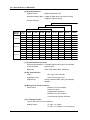
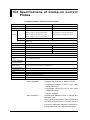
Checking Items in the Package
After opening the package, check the product as follows before use. If the
delivered product is the wrong model, any item is missing, or the appearance
is defective, contact the vendor from which you purchased the product.
CW120/121 Main Unit
Check the model and suffix (specifications) codes in the MODEL and SUFFIX
fields of the nameplate at the back of the instrument to ensure that the
instrument is exactly as specified in your purchase order.
Model and Suffix Codes
Model
Suffix Code
CW120
CW121
Power cord
-D
-F
-R
-S
Communication
interface
Option codes
Specification
Clamp-on power meter for single-phase two-wire, single-phase three-wire,
and three-phase three-wire circuits
Clamp-on power meter for single-phase two-wire, single-phase three-wire,
three-phase three-wire, and three-phase four-wire circuits
UL/CSA standard
VDE standard
SAA standard
BS standard
-1
With RS-232-C interface
-2
With RS-485 interface
/C1
Clamp-on current probe for 20/200 A (2 pieces/set)
/C2
Clamp-on current probe for 20/200 A (3 pieces/set)
/C3
Clamp-on current probe for 50/500 A (2 pieces/set)
/C4
Clamp-on current probe for 50/500 A (3 pieces/set)
/C5
Clamp-on current probe for 200/1000 A (2 pieces/set)
/C6
Clamp-on current probe for 200/1000 A (3 pieces/set)
/C7
Clamp-on current probe for 5/50 A (2 pieces/set)
/C8
Clamp-on current probe for 5/50 A (3 pieces/set)
/PB1 Meter case, carrying case, CF pack
/PM1 Meter case, carrying case, CF pack, and 91011
/PM2 Meter case, carrying case, CF pack, and 91009
No. (serial number):
Refer to this serial number on the nameplate when contacting the vendor
about the instrument.
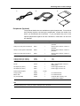
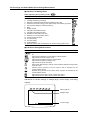
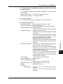
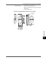
Accessories
Make sure that the package contains all the accessories listed below and that
they are all free from any damage.
Product Name
Part Number Qty
Remarks
1. Power cord
(One of the four options)
B9988YA
B9988TB
B9988YC
B9988YD
91018
91007
IM CW120-E
IM CW120P-E
-D: UL/CSA standard
-F: VDE standard
-R: SAA standard
-S: BS standerd
Color: Black, red, yellow
Color: Black, red, yellow, blue
2. Voltage probes (for CW120)
Voltage probes (for CW121)
3. User’s Manual
4. Operation Guide
2
3
4
1
1
IM CW120-E
Checking Items in the Package
1.
2.
3.
4.
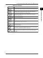
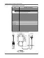
Peripherals (Optional)
The products listed below are available as optional peripherals. For technical
and ordering inquiries concerning the peripherals, contact the vendor from
which you purchased the instrument. If you purchased any one of the
optional peripherals together with the CW120/121, make sure it is free from
any damage.
Product Name
Part Number
Minimum Order Qty
Remarks
Clamp-on current probe for 20/200 A
96030
1
See the option codes for a choice of
probe kits.
Clamp-on current probe for 50/500 A
96031
1
See the option codes for a choice of
probe kits.
Clamp-on current probe for 200/1000 A
96032
1
See the option codes for a choice of
probe kits.
Clamp-on current probe for 5/50 A
96033
1
See the option codes for a choice of
probe kits.
Power supply cable
98030
1
Not applicable to CE and UL(pending)
Voltage probes (for CW121)
Voltage probes (for CW120)
91007
91018
4
3
1 set
1 set
RS-232 serial printer cable
91010
1
Printer
97010
1
With 1 thermal paper roll and 1
battery pack
AC adapter (for printer)
94006
1
Power supply 200-240 V AC
AC adapter (for printer)
94007
1
Power supply 100-120 V AC
Thermal printer paper
97080
10 rolls
Carrying case
93022
1
Meter case
93023
1
For CW120 Series
CF pack (16 MB)
97030
1
Compact flash memory and
compact flash adapter
For CW120 Series
TIP
Keep the packing box in case you need to transport the instrument.
IM CW120-E
3
Checking Items in the Package
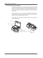
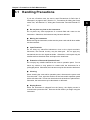
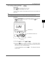
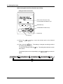
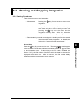
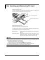
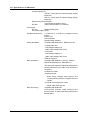
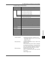
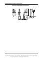
Housing CW120/121 and Accessories
The optional carrying case can accommodate the CW120 or CW121 main
unit with its current-sensing clamp-on probes and voltage probes connected
to the unit. The case can also hold such accessories as manuals and PC
cards, and so is useful for transporting a complete set of tools necessary for
measurement.
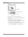
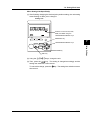
The optional meter case can be used as a stand during measurement as
shown below right. It also has a magnetic rear plate and so can be stuck to
the door of a power distribution panel or the like.
Note: Keep the meter case away from objects vulnerable to a magnetic field,
such as floppy disks.
Manual
Clamp-on current probes
Voltage probes
CW120/121 main unit
Carrying Case
4
Adjust the Velcro fastener.
Meter case
IM CW120-E
Precautions for Safe Use of the Instrument
When operating the instrument, be sure to observe the cautionary notes given below
to ensure correct and safe use of the instrument. If you use the instrument in any
other way than instructed in this manual, the instrument’s protective measures may
be impaired. Yokogawa M&C Corporation is by no means liable for any damage
resulting from use of the instrument in contradiction to these cautionary notes.
The following safety symbols are used in the instrument and this manual.
Danger! Handle with Care.
This symbol indicates that the operator must refer to an explanation in the instruction manual in
order to avoid risk of injury or death of personnel or damage to the instrument.
Direct Current
This symbol indicates DC voltage/current.
Alternating Current
This symbol indicates AC voltage/current.
ON
This symbol indicates On (power).
OFF
This symbol indicates Off (power).
Double Insulation
This symbol indicates double insulation.
WARNING
Indicates a hazard that may result in the loss of life or serious injury of the user unless the
described instruction is abided by.
CAUTION
Indicates a hazard that may result in an injury to the user and/or physical damage to the product
or other equipment unless the described instruction is abided by.
NOTE
Indicates information that is essential for handling the instrument or should be noted in order to
familiarize yourself with the instrument’s operating procedures and/or functions.
TIP
Indicates information that complements the present topic.
SEE ALSO
Indicates the reference location(s) for further information on the present topic.
IM CW120-E
5
Precautions for Safe Use of the Instrument
Strictly observe the following cautionary notes in order to avoid the risk of
injury or death of personnel or damage to the instrument due to such hazards
as electrical shock.
WARNING
● Removal of Case from the Instrument
• Do not remove the case from the instrument or disassemble/modify the instrument itself.
• Some parts of the inside of the instrument contain high-voltage and, therefore, access to
the internal assembly is extremely hazardous. For inspection and/or adjustment of the internal assembly, contact the vendor from which you purchased the instrument.
● Use of the Instrument in a Gas Atmosphere
Do not operate the instrument in a location where any flammable or explosive gas/vapor is
present. It is extremely hazardous to operate the instrument in such an atmosphere.
● Inspection of Power Source
• Before turning on the instrument, always make sure the voltage of the power source to be
applied matches the instrument’s supply voltage.
● Use of Clamp-on Current Probes
• When using clamp-on current probes, keep the circuit voltage below 600 V AC in order to
avoid possible short-circuits or accidents resulting in injury or death.
• Ensure that the rated current of the circuit you measure matches the rating of the current
probe.
• Avoid using the instrument if it has been exposed to rain or moisture or if your hands are
wet.
• Do not use clamp-on current probes with any non-insulated conductors.
● Measures In Case of Anomalies
If the instrument begins to emit smoke, becomes too hot, or gives off an unusual smell, immediately turn it off and disconnect the power cord from the outlet. Also turn off power to the
object under measurement that is connected to the instrument’s input terminals. Never attempt to use the instrument again. If any such anomalies as noted above occurs, contact the
vendor from which you purchased the instrument. Do not attempt to repair the instrument
yourself, as doing so is extremely dangerous.
● Handling of Power Cord
• Use only the cord supplied from Yokogawa M&C to prevent electric shocks and fire.
• Do not place any load on the power cord or allow the power cord to come into accidental
contact with any heat source. When unplugging the power cord from the outlet, hold its
plug, rather than holding and pulling the cord itself.
• If the power cord is damaged, contact the vendor from which you purchased the instrument.
● Fuses
Fuses built into this instrument for protection cannot be replaced by the user. When any builtin fuses need to be replaced such as because they have blown, contact the vendor from which
you purchased the instrument.
6
IM CW120-E
Contents
1
Introduction .............................................................................................................. 1
Checking Items in the Package .............................................................................. 2
Precautions for Safe Use of the Instrument .......................................................... 5
Chapter 1. Product Overview ............................................................................... 1-1
1.1
Product Overview ........................................................................................ 1-1
2
3
4
Chapter 2. Components and Indications ............................................................ 2-1
2.1
2.2
Front Panel and Connector Block ............................................................... 2-1
Connecting Input Signals ............................................................................ 2-3
5
2.3
2.4
Operation Keys and Display ........................................................................ 2-5
Overrange and Other Marks Shown during Measurement .......................... 2-6
6
Chapter 3. Precautions for Safe Measurement .................................................. 3-1
7
3.1
Handling Precautions .................................................................................. 3-1
3.2
3.3
Installation Procedure .................................................................................. 3-3
Maintaining High Precision of Measurement ............................................... 3-5
Chapter 4. Connecting Power Supply and Turning Power On/Off ................... 4-1
8
4.1
When Using AC Power Supply .................................................................... 4-1
9
4.2
4.3
When Supplying Power from Voltage Input ................................................. 4-3
Startup Screens ........................................................................................... 4-4
10
4.4
Basic Operation Flow .................................................................................. 4-6
Chapter 5. Wiring .................................................................................................. 5-1
11
5.1
Precautions for Wiring the Circuit under Test .............................................. 5-1
5.2
5.3
Diagrams of Basic Wiring ............................................................................ 5-2
Wiring the Circuit under Test with External VT/CT ...................................... 5-4
5.4
5.5
Indication and Change of Wiring Method .................................................... 5-5
Wiring Check Function ................................................................................ 5-6
13
Chapter 6. Setting Ranges and Wiring Method .................................................. 6-1
14
6.1
Ranges and Display Digits .......................................................................... 6-1
6.2
6.3
Changing Voltage Range Setting ................................................................ 6-6
Changing Current Range Setting ................................................................ 6-7
App
6.4
Changing Wiring Method Setting ............................................................... 6-10
Index
Chapter 7. Making Settings .................................................................................. 7-1
7.1
7.2
Setting Items and Item Selection ................................................................. 7-1
Setting Each Item ........................................................................................ 7-4
7.3
Setting Name of Measured-data File ......................................................... 7-32
Chapter 8. Instantaneous Value Measurement ................................................. 8-1
IM CW120-E
12
8.1
8.2
Measuring Instantaneous Values ................................................................ 8-1
Switching Display Contents ......................................................................... 8-2
8.3
8.4
Saving Data ................................................................................................. 8-4
Frequency Measurement ............................................................................ 8-7
8.5
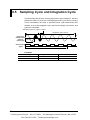
Sampling Cycle and Integration Cycle ........................................................ 8-8
7
Contents
Chapter 9. Electric Energy Measurement ........................................................... 9-1
9.1
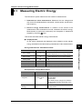
Measuring Electric Energy .......................................................................... 9-1
9.2
9.3
Starting and Stopping Integration ................................................................ 9-3
Switching Display Contents ....................................................................... 9-10
9.4
9.5
Saving Data ............................................................................................... 9-12
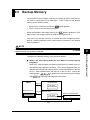
Backup Memory ........................................................................................ 9-15
9.6
9.7
External Control Input/Output .................................................................... 9-18
Meter Actions upon Power Failure and Recovery ..................................... 9-21
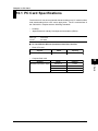
Chapter 10. PC Card ........................................................................................... 10-1
10.1
PC Card Specifications ............................................................................. 10-1
10.2
10.3
Inserting and Removing PC Card .............................................................. 10-2
Storage Capacity ....................................................................................... 10-3
10.4
10.5
Formatting PC Card .................................................................................. 10-4
Saving and Loading from/to PC Card ........................................................ 10-5
10.6
Interface with Personal Computer ............................................................. 10-7
Chapter 11 Communication Functions ............................................................ 11-1
11.1
11.2
RS-232 ...................................................................................................... 11-1
RS-485 ...................................................................................................... 11-6
11.3
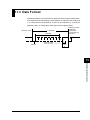
Data Format .............................................................................................. 11-9
Chapter 12. Auxiliary Functions ........................................................................ 12-1
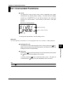
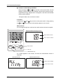
12.1
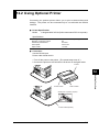
12.2
Convenient Functions ................................................................................ 12-1
Using Optional Printer ............................................................................... 12-3
Chapter 13. Troubleshooting ............................................................................. 13-1
13.1
Corrective Measures in Case of Failure .................................................... 13-1
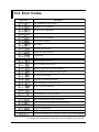
13.2
Error Codes ............................................................................................... 13-2
Chapter 14. Specifications ................................................................................. 14-1
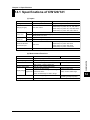
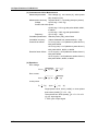
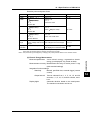
14.1
14.2
Specifications of CW120/121 .................................................................... 14-1
Specifications of Clamp-on Current Probes .............................................. 14-8
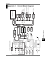
Appendix 1. Circuit Block Diagram .............................................................. App1-1
Appendix 2. Communication Commands .................................................... App2-1
1. Commands ......................................................................................... App2-2
1.1
1.2
Messages .............................................................................................. App2-2
Commands ............................................................................................ App2-4
1.3
1.4
Response .............................................................................................. App2-5
Data ....................................................................................................... App2-6
1.5
1.6
Messages on RS-485 ............................................................................ App2-8
Communication Commands .................................................................. App2-9
1.7
Output Queue and Error Queue .......................................................... App2-12
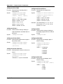
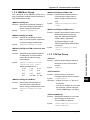
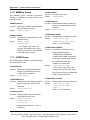
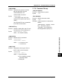
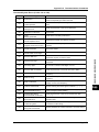
Detailed Description of Communication Commands ........................... App2-12
1.7.1 COMMunicate Group ............................................................... App2-12
1.7.2 SYSTem Group ........................................................................ App2-13
1.7.3 INTEgrate Group ...................................................................... App2-15
1.7.4 MEASure Group ....................................................................... App2-17
8
IM CW120-E
Contents
1.7.5 STATus Group .......................................................................... App2-17
1.7.6 MEMOry Group ........................................................................ App2-18
1.7.7 CARD Group ............................................................................ App2-18
1.7.8 Common Group ....................................................................... App2-19
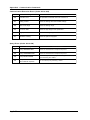
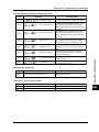
2. Error Messages ................................................................................ App2-20
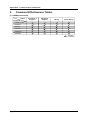
3. Command Effectiveness Tables ........................................................ App2-24
Appendix 3. File Structures and Data Items Printed ................................. App3-1
1. Overview ............................................................................................. App3-2
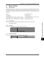
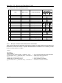
2. Measured Data ................................................................................... App3-3
2.1
File Format ............................................................................................ App3-3
2.2
Print Format ........................................................................................... App3-5
3. Settings ............................................................................................... App3-6
3.1
File Format ............................................................................................ App3-6
3.2
3.3
Output Format and Data Values ............................................................ App3-7
Print Format ........................................................................................... App3-9
4. Automatic File Naming ...................................................................... App3-10
Index ............................................................................................................... Index-1
IM CW120-E
9
Chapter 1. Product Overview
1.1 Product Overview
1
energy (watt-hours).
•
CW120: Supports single-phase two-wire, single-phase three-wire, and
three-phase three-wire circuits.
•
CW121: Supports single-phase two-wire, single-phase three-wire, threephase three-wire, and three-phase four-wire circuits.
The following explains the features of the CW120/121, shows a schematic
diagram of their functions, and describes the contents displayed on the
screen in each measurement mode.
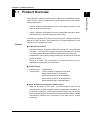
Features
● A Wealth of Functions
• Fast data saving for a long time: Data can be saved at 1-second intervals
at fastest. A PC card slot for large removable memories such as flash
ATA and compact flash cards allows measurement over a long time.
• Instantaneous value saving: Simply pressing the SAVE key will save the
measured values.
• Wiring error check: The connections are checked and any error is
displayed before the start of measurement.
● Broad Ranges
•
•
Voltage range:
Current range:
150/300/450 V
4 types of clamp-on probes can be used.
96033 clamp-on probe: 5/10/20/50 A
96030 clamp-on probe: 20/50/100/200 A
96031 clamp-on probe: 50/100/200/500 A
96032 clamp-on probe: 200/500/1000 A
● Ease of Data Processing and Communication
Data can be saved to a PC card. Via communication, data can be
transferred to a personal computer and the measurement conditions can
be set from a computer. As the communication interface, you can choose
(when ordering) RS-232 or RS-485; the RS-485 interface allows multiple
CW120s and CW121s to be connected on the same line for remote
monitoring.
IM CW120-E
1-1
Product Overview
The CW120/121 clamp-on power meters measure the fundamental electric
power factors, namely, instantaneous power-related values and electric
1.1 Product Overview
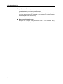
● Compact Design
•
The CW120/121 are sufficiently compact to be installed inside a cubicle or
power distribution panel during measurement.
•
The 96033 current-sensing probe with a 5 to 50 A range is designed for
use in a narrow space, so is useful for measurement inside a power
distribution panel with dense wiring.
● Easy-to-see Display Screen
Despite the compact body, the large back-lit LCD enables easy
measurement in a dark place.
1-2
IM CW120-E
1.1 Product Overview
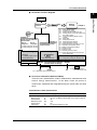
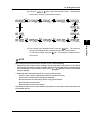
● Schematic Function Diagram
1
Measurement
screen
7.2.1
7.2.2
7.2.3
7.2.4
key
7.2.5
Chapter 9
Electric energy (watt-hour)
measurement
Start of
integration
End of
integration
7.2.8 Setting integration start time
7.2.9 Setting integration stop time
Chapter 8
Instantaneous value
measurement
Data saving
Data saving
Auto-saving
7.2.7 Setting output interval
7.2.6
7.2.7
7.2.8
7.2.9
7.2.10
7.2.11
7.2.12
7.2.13
7.2.14
7.2.15
7.2.16
File: MWTH000.CSV
RS-232
Chapter 7
Setting device number
Loading/saving settings
Deleting file and formatting PC card
Clearing electric energy count (watt-hours)
and resetting system
Copying and clearing backup memory
contents
Setting date
Setting output interval
Setting integration start time
Setting integration stop time
Setting whether to save data to PC card
Selecting communication device
Making communication settings
Setting VT ratio
Setting CT ratio
Selecting probe to be used
Setting decimal point and unit of electric
energy (watt-hours)
key
File: AWTH000.CSV
External control terminals
Input
Output
Setting
screens
key
Saving settings
7.2.2 Loading/saving setting File: WTH000.SET
Communication interface
(chosen when ordering)
RS-485
PC card
PC
Printer
7.2.11 Selecting communication device
PC
7.2.10 Setting whether to
save data to PC card
● On-screen Information (Measured Data)
There are two measurement modes: instantaneous measurement and
electric energy measurement. In the latter mode, the power is
continuously measured and integrated during the preset start and stop
times.
Instantaneous value measurement
IM CW120-E
Item
Unit
Displayed Name
Rms voltage
Rms current
Active power
Reactive power
Power factor
Frequency
V
A
W
Var
—
Hz
V1, V2, V3 (differs depending on the wiring method)
A1, A2, A3 (differs depending on the wiring method)
W
Var
PF
Hz (input frequency of V1)
1-3
Product Overview
Power-on
1.1 Product Overview
Electric energy measurement
Item
Unit
Displayed Name
Active electric energy
Wh
Wh
Regenerative electric energy
Wh
Only saved; not displayed
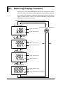
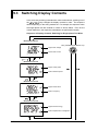
Six items of instantaneous value measurement
The screen changes sequentially each time a cursor-movement (UP, DOWN,
LEFT, or RIGHT) key is pressed as follows (display contents differ depending
on the wiring method):
Displayed Item
Phase Wires
Single-phase two wires (1∅2W)
Single-phase three wires (1∅3W)
Three-phase three wires (3∅3W)
Three-phase four wires (3∅4W)
1-4
Display
Position
Upper row
Lower row
Upper row
Lower row
Upper row
Lower row
Screen Screen Screen Screen Screen Screen
1
2
3
4
5
6
V1
W
PF
Wh
A1
Var
Hz
TIME
V1
A1
W
PF
Wh
V2
A2
Var
Hz
TIME
V1
V3
A2
W
PF
Wh
V2
A1
A3
Var
Hz
TIME
IM CW120-E
Chapter 2. Components and Indications
2.1 Front Panel and Connector Block
2
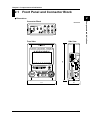
● Dimensions
Unit: mm
Front View
161
Side View
117
IM CW120-E
51
2-1
Components and Indications
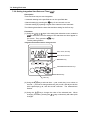
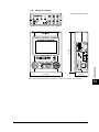
Connector Block
2.1 Front Panel and Connector Block
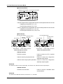
● Connector Block
Voltage input terminals Current input terminals
CW120: Supports from single-phase two-wire to three-phase three-wire circuits
Voltage input terminals: N, V1, V2
Current input terminals: CH1, CH2
CW121: Supports from single-phase two-wire to three-phase four-wire circuits
Voltage input terminals: N, V1, V2, V3
Current input terminals: CH1, CH2, CH3
● Side Panels
PC card eject button
PC card slot
Power switch
RS-232
connector
PC card eject button
External control
terminals
Power supply connector
RS-485 screw
terminals
PC card slot
Power switch
Model with RS-232 interface
Power supply connector
Model with RS-485 interface
RS-232 interface
RS-232 connector
: Used to connect to a PC or printer
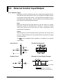
Internal control input (IN) terminals
(optional).
: Used to connect the integration
start/stop input signals.
Internal control output (OUT) terminals : Used to connect the integration
start/stop output signals.
SEE ALSO
For details of external control input/output, see Section 9.6, “External Control Input/Output.”
RS-485 interface
RS-485 screw terminals
: Used to connect a shielded cable
and terminator.
SEE ALSO
For details of the RS-485 interface, see Section 11.2, “RS-485.”
2-2
IM CW120-E
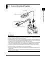
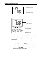
2.2 Connecting Input Signals
2
Components and Indications
Ring marker
Clamp-on current probe
Voltage probe (black)
Voltage probe (red)
WARNING
• Thoroughly read Section 5.1, “Precautions for Wiring the Circuit under Test.”
• When connecting the CW120/121, turn off the circuit under test. It is extremely dangerous to
connect or disconnect probes to/from a live circuit.
• Be extremely careful not to connect any voltage-mode circuit to the current input terminals or
any current-mode circuit to the voltage input terminals. Miswiring can result in not only damage to the circuit or equipment under test but also injury to personnel.
• Do not connect any probes which are not necessary (i.e., not used) for the current measurement, even though multiple probes can be connected to the CW120/121 at the same time.
• Do not use any probe other than the clamp-on current probes or voltage probes supplied.
• Do not use a clamp-on current probe for a non-insulated conductor.
• Ensure that the rating of the clamp-on current probe you use matches the rating of the measured current.
• Before connecting a clamp-on current probe to the CW120/121, make sure the plug is inserted
with the correct H/L polarities.
IM CW120-E
2-3
2.2 Connecting Input Signals
● Differentiating between Voltage Probes
Voltage probes are differentiated by color for correct connections.
• Probe for terminal N: Probe with a black alligator plug
• Probes for terminals V1 to V3: Probes with a red, yellow, or blue alligator
plug
Accompanying probes
CW120: Three (black, red, and yellow)
CW121: Four (black, red, yellow, and blue)
● Differentiating between Clamp-on Current Probes
Use accompanying ring markers (of four different colors) to differentiate
clamp-on current probes for correct connections.
CW120: Terminals CH1 to CH2
CW121: Terminals CH1 to CH3
Use of Ring Markers
Attach ring markers of the same color to both ends of the probe cable for easy
identification.
CAUTION
Be careful not to damage a probe when attaching ring markers.
2-4
IM CW120-E
Test Equipment Depot - 800.517.8431 - 99 Washington Street Melrose, MA 02176
FAX 781.665.0780 - TestEquipmentDepot.com
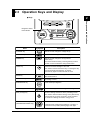
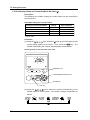
2.3 Operation Keys and Display
● Keys
2
Components and Indications
Integration status
LED indicator
Name
Key Symbol
Description
V RANGE key
Used to set and change the voltage range.
A RANGE key
Used to set and change the current range.
WIRING key
Used to set and change the wiring method
(phase lines).
Also used to check the wiring. Pressing this key for three
seconds or more accesses the wiring check screen.
LIGHT key
Switches on/off the backlight of the LCD.
Also used to lock and unlock the keys. Pressing this key
for three seconds locks the keys. To unlock,
press the key again for three seconds or more.
SAVE key
MEAS/SET key
Saves the measured data during instantaneous
value measurement.
Switches over the display between the measurement
and setting screens.
START&STOP key
Starts and stops integration.
ENTER key
Confirms an entry such as a change to a setting.
ESC (escape) key
Cancels a setting and returns to the preceding screen.
Also used to clear the electric energy count (watt-hours).
Pressing this key for three seconds or more accesses
the screen for clearing the electric energy count.
Cursor movement keys
(UP/DOWN/LEFT/RIGHT keys)
In measurement screen: Switches the display contents.
In setting screen: Changes the selection or number, or
moves the cursor position (flashing digit) over digits.
Integration status LED indicator: Lit when the integration is carried out, and flashes when it is on stand-by.
IM CW120-E
2-5
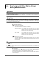
2.4 Overrange and Other Marks Shown
during Measurement
WARNING
When the overrange mark appears with the range set to a maximum, it means that the input
exceeds the maximum allowable level of the CW120/121. Do not apply an input level higher than
the maximum allowable input level.
CAUTION
When measuring an input signal level exceeding the rated range, use a voltage transformer (VT)
or current transformer (CT). When using a VT or CT, thoroughly read Section 5.3, “Wiring the
Circuit under Test with External VT/CT.”
● Overrange Indications
: Indicates an overvoltage.
This mark appears in the following conditions.
150/300 V range: If the sampled value exceeds 200% of the rated
voltage or if the rms value of the measured voltage
exceeds 110% of the rated range
450 V range:
If the sampled value exceeds 156% of the rated
voltage or if the rms value of the measured voltage
exceeds 110% of the rated range
: Indicates an overcurrent.
This mark appears if the sampled value exceeds 300% of the rated
current or if the rms value of the measured current exceeds 110% of
the rated range.
TIP
The
mark appears when any one of the input signals from terminals V1 to V3 satisfies the condi-
tions noted above.
The
mark appears when any one of the input signals from terminals CH1 to CH4 satisfies the
conditions noted above.
indication
The CW120/121 show
instead of a usual number representing the
measured value if any one of the following conditions is met.
The number representing the measured value exceeds 9999, the maximum
number displayed.
2-6
IM CW120-E
2.4 Overrange and Other Marks Shown during Measurement
Voltage - 150/300 V range:
If the sampled value exceeds 200% of the rated voltage or if the rms value of
the measured voltage exceeds 130% of the rated range
Voltage - 450 V range:
Current:
If the sampled value exceeds 300% of the rated voltage or if the rms value of
the measured voltage exceeds 130% of the rated range
● Indications When the Measured Value Is Too Small
Displayed Item
Condition
Indication
Voltage
≤1.5 V
0V
Current
≤0.4% of rated range
0A
Active power
≤0.17% of rated range
0W
Reactive power
≤0.17% of rated range
0 Var
Active electric energy
≤0.17% of rated range
0 Wh (integration stopped)
Displayed Item
Reactive power
Condition
V1 input ≤10% of rated range; or frequency
≤40 Hz or ≥70 Hz
Indication
---- Var
Power factor
The voltage or current is displayed as
; or
V1 input ≤10% of rated range; or frequency
≤40 Hz or ≥70 Hz
---- PF
Frequency
≤40 Hz or ≥70 Hz
---- Hz
TIP
Even when an instantaneous value is displayed as
, the integration calculation is carried out continuously. The accuracy of the electric energy value, however, is undefined in this case.
IM CW120-E
2-7
Components and Indications
If the sampled value exceeds 156% of the rated voltage or if the rms value of
the measured voltage exceeds 110% of the rated range
2
2.4 Overrange and Other Marks Shown during Measurement
● Indications of Setting Items
Mark appearing during setting mode:
Setting Item
1.
2.
3.
4.
5.
6.
7.
8.
9.
10.
11.
12.
13.
14.
15.
16.
Displayed Mark
Device number
Loading and saving of settings
Deletion of measured-data file and formatting of PC card
Clearance of electric energy count (watt-hours) and resetting of system
Copying and clearance of backup memory
Date
Output interval
Integration start date and time
Integration stop date and time
Whether to save data to PC card
Selection of communication device
Communication settings
VT ratio setting
CT ratio setting
Probe selection
Decimal position and unit selections for electric energy (watt-hours)
● Indications during Measurement
Displayed Mark
Lights when integration is carried out; flashes when integration is on standby.
Lights when integration is controlled by external signals.
Lights when PC card memory is full.
Lights when the backup memory contains data.
Lights when the battery voltage is low.
Lights when the keys are locked.
Lights when data saving to the PC card is enabled; flashes during access
to the PC card.
Flashes during access to the PC when a PC is selected as the
communication device.
Flashes during access to the printer when a printer is selected as the
communication device.
Lights when the VT ratio is set at a value other than 1.
Lights when the CT ratio is set at a value other than 1.
Indications for current settings of voltage range, current range, and wiring
method:
Wiring method
Voltage range
Current range
2-8
IM CW120-E
2.4 Overrange and Other Marks Shown during Measurement
● Meanings of Messages
Displayed Message
Meaning
Appears during standby of integration when set to start at a set date and time.
Appears when integration has finished normally with the set integration
start/stop dates and times.
Appears when a power failure has occurred (or the power has been turned off)
during standby or integration.
Appears when the backup data is copied from the backup memory to the PC
card.
Appears when a PC card is not inserted.
Shows the file number and data record number when saving measured
instantaneous values.
Shows the file number when integration begins in the case that data saving to
a PC card is enabled but the filename is not specified.
Appears when integration begins in the case that data saving to a PC card is
enabled and the filename is specified. The digits following “FILE” indicate
“defined.”
IM CW120-E
2-9
Components and Indications
Appears during standby of integration when a past point of time is set as the
integration start time and date and integration will begin at the nearest
appropriate time (determined by the output interval).
2
Chapter 3. Precautions for Safe Measurement
3.1 Handling Precautions
If you are a first-time user, be sure to read “Precautions for Safe Use of
Instrument” on pages 4 and 5, Section 5.1, “Precautions for Wiring the Circuit
●
Do not place any load on the instrument.
Do not place any other equipment of a vessel filled with water on the
instrument. Otherwise, the instrument may become defective.
●
Moving the instrument
Before moving the instrument, make sure the power cord and all other cables
are disconnected.
●
Input Terminals
Do not bring any electrified substance close to the signal terminals.
Otherwise, the internal circuitry may be destroyed. Do not apply any
mechanical shock to the signal terminals. Otherwise, such impact may be
transformed into electrical noise and input to the instrument.
● Protection of Case and Operation Panel
Do not spray any volatile chemical on the case or operation panel. Do not
leave any rubber or vinyl product in contact with the instrument for a
prolonged period. Otherwise, the instrument may be discolored or deformed.
●
Cleaning
When cleaning the case and/or operation panel, disconnect the power cord
from the outlet. Then, wipe the surfaces of the case and/or operation panel
with a soft clean cloth. Do not use chemicals such as benzine or paint thinner.
Otherwise, the instrument may be discolored or deformed.
●
Display Screen
When the instrument is shipped from the factory, the display screen is
covered with a protective film. Remove the film before you begin using the
instrument.
IM CW120-E
3-1
3
Precautions for Safe Measurement
under Test,” and Section 5.3, “Wiring the Circuit under Test with External VT/
CT.”
3.1 Handling Precautions
● After Use
After use, disconnect the power cord from the outlet.
Precautions for Use of the Clamp
CAUTION
• The clamping CT (current transformer) is precision assembled to ensure high performance.
When using the clamp, do not apply any intense mechanical shock, vibration or force to the
clamping CT.
• If dust or any other foreign matter gets in the clamping CT, do not shut the clamping cores
tight. First remove the dust and then make sure the clamping cores on both sides close
smoothly.
3-2
IM CW120-E
3.2 Installation Procedure
Install the CW120/121 in a location that satisfies the following conditions.
● Indoors
● Ambient Temperature and Humidity
0°C to 50°C
5 to 85% RH (no condensation)
● Altitude of Location
• Altitude: 2000 m or less
● Overvoltage Categories (CAT.)
“Installation category (Overvoltage category)” describes a number which
defines a transient overvoltage condition. It implies the regulation for
impulse withstand voltage.
INSTALLATION CATEGORY (OVERVOLTAGE CATEGORY) II:
Local level, appliances, PORTABLE EQUIPMENT etc., with
smaller transient overvoltages than INSTALLATION CATEGORY
(OVERVOLTAGE CATEGORY) III.
INSTALLATION CATEGORY (OVERVOLTAGE CATEGORY) III:
Distribution level, fixed installation, with smaller transient
overvoltages than INSTALLATION CATEGORY
(OVERVOLTAGE CATEGORY) IV.
INSTALLATION CATEGORY (OVERVOLTAGE CATEGORY) IV:
Primary supply level, overhead lines, cable systems etc. This
category is not relevant to this standard.
The CW120/121 meet the following overvoltage categories with the
respective usage voltages.
Voltage measurement circuit: 600 V, CAT III, and 300 V, CAT IV
Power supply:
240 V, CAT II
● Pollution Degree
“Pollution degree” describes the degree to which a solid, liquid, or gas
which deteriorates dielectric strength or surface resistivity is adhering.
“2” applies to normal indoor atmosphere.
Normally, only non-conductive pollution occurs. Occasionally, however,
temporary conductivity caused by condensation must be expected.
The CW120/121 meet the “Pollution degree 2”.
CAUTION
• When using or installing two or more CW120/121 power meters, leave a distance of at least 10
mm (0.4") between them.
• When putting a power meter inside a power distribution panel or the like, leave a space of at
least 10 mm (0.4") from a wall and ensure that excess pressure may not be applied to the
protruding plugs and jacks on the terminals.
IM CW120-E
3-3
Precautions for Safe Measurement
• Ambient temperature:
• Ambient humidity:
3
3.2 Installation Procedure
● Level Location
Do not install the CW120/121 in an unstable or inclined location;
inaccurate measurements may result.
● Other Conditions
Do not install the CW120/121 in a location that is:
• exposed to direct sunlight or close to a heat source;
• close to a noise source such as high-voltage equipment or a power
source;
• exposed to a relatively large amount of lampblack, steam, dust, or
corrosive gas;
• exposed to frequent mechanical vibration;
• close to a source of strong electromagnetic fields; or
• unstable.
3-4
IM CW120-E
3.3 Maintaining High Precision of
Measurement
To achieve a high precision of measurement, use the CW120/121 under the
following conditions.
23° ±5°C
• Ambient humidity:
35 to 75% RH (no condensation)
When installing the CW120/121 in a location where the ambient relative
humidity is 30% or less, use such equipment as an anti-static mat to prevent
electrostatic discharge.
If you move the CW120/121 from an area of low temperature and humidity to
an area of high temperature and humidity or if there is a sudden change in the
ambient temperature, condensation may occur in the meter. If this happens,
let the meter stand for at least one hour to allow it to adapt to the new ambient
temperature and for condensation to evaporate. Then, start operating the
meter.
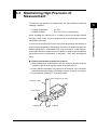
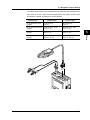
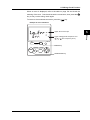
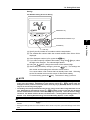
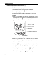
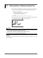
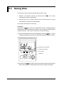
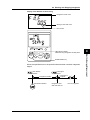
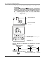
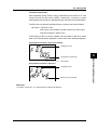
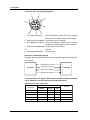
● Relationship between Clamp and Conductor
1. When performing a measurement, hold the clamp-on probe so that the
conductor cable runs through the center of the clamping CT.
2. Ensure that the orientation of the clamp to the direction of the conductor
cable (from the power supply to the load) is correct, as shown in the figure.
3. Ensure that the clamping CT is properly closed.
Power supply source side
Conductor cable
Joint section
Clamping CT
IM CW120-E
Load side
3-5
Precautions for Safe Measurement
• Ambient temperature:
3
Chapter 4. Connecting Power Supply and Turning Power On/Off
4.1 When Using AC Power Supply
● Before Connecting Power Supply
There is a danger of electric shock or damage to the meter. Observe the
following warning notes.
WARNING
4
• Before connecting the power cord, make sure the power-source voltage matches the rated
supply voltage.
• Before connecting the power cord, also make sure the power switch of the CW120 or CW121 is
turned off.
• If the CW120 or CW121 will not be used for a prolonged period, disconnect the power cord
from the outlet.
• Do not place any load on the power cord or allow the power cord to come into accidental
contact with a heat source.
• Be sure to hold the plug of the power cord, rather than holding and pulling the cord itself,
when disconnecting it from the outlet.
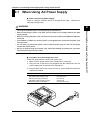
● Procedure for Connecting Power Cord
Follow the steps below to connect the power cord.
1. Make sure the power switch of the CW120/121 is turned off.
2. Plug one end of the power cord supplied with the CW120/121 into the
power supply jack on the side of the CW120/121.
3. Plug the other end of the power cord into a power outlet that meets the
requirements below.
Required Power Ratings
Rated supply voltage
Allowable supply voltage range
Rated power supply frequency
Allowable supply frequency range
Maximum power consumption
IM CW120-E
100 to 240 V AC
90 to 264 V AC
50 or 60 Hz
48 to 63 Hz
8 VA (at 240 V AC)
4-1
Connecting Power Supply and Turning Power On/Off
• Use only the dedicated power cord supplied by the manufacturer.
4.1 When Using AC Power Supply
NOTE
• When plugging and unplugging the power cord into/from the CW120 or CW121, ensure that the
PC card eject button is depressed.
• The CW120 or CW121 will not work if the fuse built into the power supply circuit of the CW120
or CW121 has blown.
• Built-in fuses cannot be replaced by the user. For replacement, contact the vendor from which
you purchased the instrument.
4-2
IM CW120-E
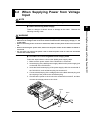
4.2 When Supplying Power from Voltage
Input
NOTE
The 98030 power supply cable is not applicable to CE and UL (pending).
● Before Connecting Power Supply
WARNING
• Use only the optional power cable (part No. 98030) supplied by the manufacturer.
• Make sure the voltage of the circuit to be measured matches the rated supply voltage (i.e., 100
to 240 V AC).
• Before connecting to the circuit to be measured, make sure the power to the circuit is turned
off.
• Before connecting the power cable, make sure the power switch of the CW120 or CW121 is
turned off.
• Do not place any load on the power cord or allow the power cord to come into accidental
contact with a heat source.
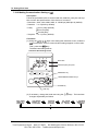
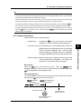
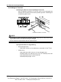
● Procedure for Connecting 98030 Power Supply Cable
Follow the steps below to connect the 98030 power supply cable.
1. Make sure the power switch of the CW120/121 is turned off.
2. Insert the plug of the 98030 power supply cable into the power supply jack
on the side of the CW120/121.
3. Insert the black banana plug of the power supply cable into terminal N of
the CW120/121, and red banana plug into terminal V1.
4. Connect the black plug of the voltage probe to the black banana plug, and
the red plug of the probe to the red banana plug.
5. Check that the power to the circuit to be measured is turned off, and then
connect the voltage probes to the circuit.
Black
Black
Red
Red
IM CW120-E
4-3
4
Connecting Power Supply and Turning Power On/Off
There is a danger of electric shock or damage to the meter. Observe the
following warning notes.
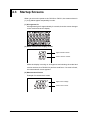
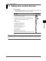
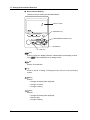
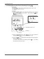
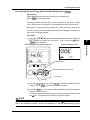
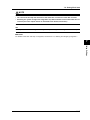
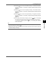
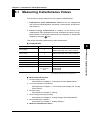
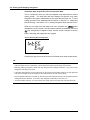
4.3 Startup Screens
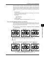
When you turn on the power to the CW120 or CW121, the screens shown in
(1) to (3) below appear sequentially in order.
(1) All-segment On
All segments light for approximately 2 seconds, then the screen changes
to the model and version display.
(2) Model and Version Display Screen
Upper: Model number
Lower: Version number
While the display is turning on all segments and showing the model and
version numbers, the CW120/121 performs a self-test. If no error is found,
the measurement screen appears.
(3) Measurement Screen
Example of measurement screen
Upper: Rms voltage
Lower: Rms current
4-4
IM CW120-E
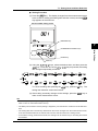
4.3 Startup Screens
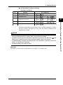
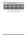
● Self-test Details and Error Handling
Test Items and Errors
No.
Test Item
Error Number(s)
Backup SRAM check
2
EEPROM check
to
3
Real-time clock check
to
4
Setting check
to
5
External memory controller check
@
4
If an error is found during the self-test, an error number is displayed. Confirm
the error number and press any key, then the screen changes to the
measurement screen.
NOTE
• If an error is found with any of test item Nos. 1, 3, and 4 (backup SRAM check, real-time clock
check, and setting check), the settings, date, and time will be initialized.
• The above situation may occur when the backup battery has become flat. When the
battery) sign is displayed on the screen, the backup battery needs to be replaced.
(low
• The backup battery cannot be replaced by the user. For replacement, contact the vendor from
which you purchased the instrument.
• The backup battery life is about 10 years.
SEE ALSO
For details of errors and the countermeasures, see Chapter 13, “Troubleshooting.”
IM CW120-E
4-5
Connecting Power Supply and Turning Power On/Off
1
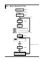
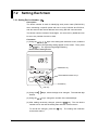
4.4 Basic Operation Flow
Connect power supply
to CW120/121
Chapter 4
Turn on power to
CW120/121
Chapter 4
Startup screens
Measurement screen
Chapter 4
When no setting is needed
key
Setting screen
Chapter 7
key
Measurement
screen
key : Calls up wiring setting
key : Calls up voltage range setting
key : Calls up current range setting
Perform wiring
Chapter 6
Chapter 5
key : Check wiring for error
(press 3 sec)
key
When skipping wiring check
Check result
screen
Chapter 5
key
Measurement
Instantaneous value measurement
Electric energy measurement
4-6
Chapter 8
Chapter 9
IM CW120-E
Chapter 5. Wiring
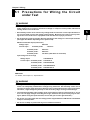
5.1 Precautions for Wiring the Circuit
under Test
WARNING
• When wiring the CW120 or CW121, or when it is turned off, turn off the circuit under test. It is
highly dangerous to connect or disconnect voltage or clamp-on current probes without first
turning off the circuit under test.
• Do not apply any input level higher than the following to the voltage or current input terminals
(the upper limit differs depending on the probe used):
Maximum allowable input (continuous)
Voltage input:
Current input –
495 Vrms
for 96033 probe:
130 Arms
for 96030 probe:
250 Arms
for 96031 probe:
625 Arms
for 96032 probe:
700 Arms (1000 Arms for 5 minutes)
Input ratings for each range
Voltage input:
150/300/450 V
Current input – for 96033 probe:
5/10/20/50 A
for 96030 probe:
20/50/100/200 A
for 96031 probe:
50/100/200/500 A
for 96032 probe:
200/500/1000 A
SEE ALSO
For details, see Chapter 14, “Specifications.”
WARNING
• If using an external voltage transformer (VT) or current transformer (CT), make sure the transformer can adequately withstand the voltage being measured. Be extremely careful not to
allow the secondary stage of the CT to become open-circuited while the CT is being electrified.
Otherwise, a high-voltage may develop on the secondary stage, causing extreme danger.
• The maximum allowable input voltage range of the external control input terminals is -0.5 to
5.5 V. Do not apply voltages exceeding this range, otherwise the input circuitry may be damaged. (When wiring the input terminals, ensure that you wire the right terminals.)
• Do not use any probe other than the voltage probes supplied with the CW120/121 or dedicated
clamp-on current probes.
• Do not use a clamp-on probe with any non-insulated conductors.
IM CW120-E
5-1
5
Wiring
• Be extremely careful not to connect any voltage-mode circuit to the current input terminals or
any current-mode circuit to the voltage input terminals. Miswiring can result in not only damage to the circuit under test or equipment under test but also injury to personnel.
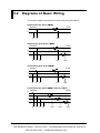
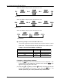
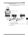
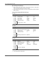
5.2 Diagrams of Basic Wiring
This section explains the methods of basic wiring using illustrations.
∅2W)
Single-phase two wires (1∅
1
SOURCE
LOAD
N
N
V1
CH1
∅3W)
Single-phase three wires (1∅
1
SOURCE
LOAD
N
2
N
V1
V2
CH1
CH2
∅3W)
Three-phase three wires (3∅
1
SOURCE
LOAD
2
3
N
V1
V2
CH1
CH2
∅4W): Only for CW121
Three-phase four wires (3∅
N
SOURCE
LOAD
1
2
3
N
V1
V2 V3
CH1
CH2
CH3
5-2
IM CW120-E
Test Equipment Depot - 800.517.8431 - 99 Washington Street Melrose, MA 02176
FAX 781.665.0780 - TestEquipmentDepot.com
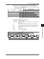
5.2 Diagrams of Basic Wiring
The table below shows the correspondences between the voltage/current
units (sets of a unit + input number) displayed on the screen and the input
terminals for voltage and clamp-on current probes.
Wiring Method
(Phase Lines)
Voltage Inputs
Current Inputs
Single-phase two wires
(1∅2W)
Terminals: N-V1
Units: V1
Terminals: CH1
Units: A1
Single-phase three wires
(1∅3W)
Terminals: N-V1, N-V2
Units: V1, V2
Terminals: CH1, CH2
Units: A1, A2
Three-phase three wires
(3∅3W)
Terminals: N-V1, N-V2
Units: V1, V2
Terminals: CH1, CH2
Units: A1, A2
Three-phase four wires*
(3∅4W)
Terminals: N-V1, N-V2, N-V3
Units: V1, V2, V3
Terminals: CH1, CH2, CH3
Units: A1, A2, A3
5
IM CW120-E
5-3
Wiring
* Only for CW121
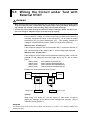
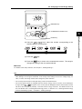
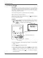
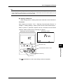
5.3 Wiring the Circuit under Test with
External VT/CT
WARNING
• When using an external current transformer (CT), be careful not to allow the secondary stage
of the CT to become open-circuited while the primary stage is being electrified. Otherwise, a
high-voltage may develop on the secondary stage, causing extreme danger.
• A measuring current flows through the bold lines shown in the figure below. For these lines,
use wires having an adequate margin of current-carrying capacity.
If the maximum voltage or current level being measured exceeds the
maximum measurement range of the CW120/121, use an external voltage
transformer (VT) or current transformer (CT). This strategy enables the
voltage or current levels beyond the maximum range to be measured.
When to use a VT and how?
If the maximum voltage of the circuit exceeds 450 V, connect an external VT
and connect the secondary stage of the VT to the voltage input terminals.
When to use a CT and how?
If the maximum current of the circuit exceeds the following value, connect an
external CT and clamp the secondary stage wire of the CT with a current
probe.
96033 probe:
50 A (rated at 5/10/20/50 A)
96030 probe:
200 A (rated at 20/50/100/200 A)
96031 probe:
500 A (rated at 50/100/200/500 A)
96032 probe:
1000 A (rated at 200/500/1000 A)
Example for single-phase two wires (1∅2W)
Source
1
Load
N
V
L
VT
CT
v
Voltage input
N
V1
CH1
Current input
Scaling
When using a VT and/or CT, you can set the VT ratio and/or CT ratio to
display the readings of the primary circuit voltages and currents. (This is
called the scaling function.)
SEE ALSO
For details of how to set the CT and VT ratios, see Sections 7.2.13 and 7.2.14, “Setting VT Ratio” and
“Setting CT Ratio.”
5-4
IM CW120-E
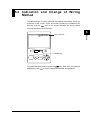
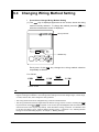
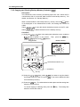
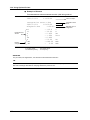
5.4 Indication and Change of Wiring
Method
The abbreviations for wiring methods are labeled immediately above the
screen as 1∅2W, 1∅3W, 3∅3W, and 3∅4W (3∅4W is not included for the
CW120), and the
sign on the screen indicates the wiring method
currently selected in the CW120/121.
5
Wiring
Wiring methods
WIRING
WIRING key
To change the wiring method, press the
key. Each time you press the
WIRING key, the
moves to change the selected wiring method.
IM CW120-E
5-5
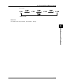
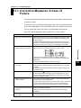
5.5 Wiring Check Function
WARNING
• It is important to check the wiring for correct and safe measurement. Check the wiring with
reference to Chapter 3, “Precautions for Safe Measurement,” Section 5.1, “Precautions for
Wiring the Circuit under Test,” and Section 5.3, “Wiring the Circuit under Test with External VT/
CT.”
• Check the connections of voltage probes, and for clamp-on current probes, check the models
(ratings), H/L polarities of the plugs and jacks, and the arrow symbols on the clamps corresponding to the source-to-load directions of the circuit.
• Do not use a clamp-on current probe with any non-insulated conductor.
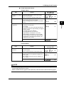
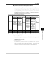
● Check Items
The following items are checked and judged, and then the result of each
check item will be displayed as shown on the next page.
For each voltage input:
For each current input:
1. Existence of input voltages
2. Frequency detection
1. Existence of input currents
2. Clamp directions
3. Voltage phase sequence
NOTE
• Measurement is not performed during the wiring check.
• The wiring check cannot be carried out during continuous measurement.
5-6
IM CW120-E
5.5 Wiring Check Function
● Check Items and Criteria
Voltage Inputs
Item
Criteria
Error Message
(in lower row)
1. Existence of voltage • If an input level is 10% or less of the range,
inputs
then an error results.
• Else, the frequency detection takes place.
Error message
2. Frequency detection • If the frequency of input V1 exceeds the 40 to
70 Hz range, then an error results.
• Else, the voltage phase sequence check takes
place.
Error message
Hz
5
Error message
For 1∅2W or 1∅3W:
• This item is not checked.
For 3∅3W:
• If V2 leads V1 by more than approximately 80
degrees or less than approximately 40 degrees,
an error results.
For 3∅4W (only for the CW121):
• If V2 lags behind V1 by more than
approximately 140 degrees or less than
approximately 100 degrees, an error results.
• Or if V3 leads V1 by more than approximately
140 degrees or less than approximately 100
degrees, an error results.
• Else, “Good” is displayed.
V
V
Current Inputs
Item
1. Existence of input
currents
2. Clamp directions
Criteria
Error Message
(in lower row)
• If an input level is 1% or less of the range, then
an error results.
• Else, the clamp direction check takes place.
Error message
• For any wiring method other than 3∅3W, if the
power of one or more phases is negative, an
error results.
• For 3∅3W, if the whole power is negative, an
error results.
Error message
A
A
• Else, “Good” is displayed.
A
NOTE
• As the wiring is judged on the above criteria, an error may result even when wiring is correct or
wrong wiring may pass the check.
• When a measured value appears to be abnormal, check the above criteria and wiring again.
IM CW120-E
5-7
Wiring
3. Voltage phase
sequence
V
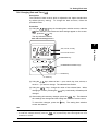
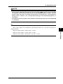
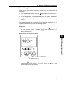
5.5 Wiring Check Function
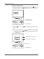
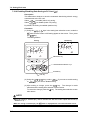
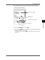
● Carrying out Wiring Check
key for at
(1) When the measurement screen is displayed, press the
least three seconds, and “
” appears on the screen and flashes.
WIRING
Press WIRING key for
at least three seconds.
START
&STOP
START&STOP key
(2) Press the
begins.
key. Then, “
” stops flashing and the wiring check
(3) When no error has been found, “
and lower rows. Press the
” is displayed on both the upper
key to return to the measurement screen.
When no error
Upper: Judgment of current inputs
Lower: Judgment of voltage inputs
WIRING
WIRING key
START
&STOP
START&STOP key
5-8
IM CW120-E
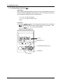
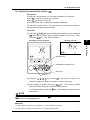
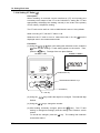
5.5 Wiring Check Function
When an error is displayed, refer to the table on page 5-8 and check the
meaning of the error. Check and correct the connections, then press the
key to carry out the wiring check again.
key.
To return to the measurement screen, press the
Example of error indications
5
Upper: No current input
Wiring
Lower: Voltage phase sequence error
(
when frequency error)
WIRING
WIRING key
START
&STOP
START&STOP key
IM CW120-E
5-9
Chapter 6. Setting Ranges and Wiring Method
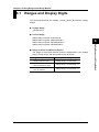
6.1 Ranges and Display Digits
The following describes the voltage, current, power, and electric energy
ranges.
● Voltage Range
150/300/450 V
● Current Range
96033 clamp-on probe: 5/10/20/50 A
96030 clamp-on probe: 20/50/100/200 A
96031 clamp-on probe: 50/100/200/500 A
6
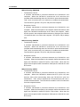
● Range of Active and Reactive Powers
The range of active and reactive powers is determined by the voltage
range, current range, and wiring method set as follows:
Wiring Method (Phase Lines)
IM CW120-E
Power Range
Single-phase two wires
Voltage range × current range
Single-phase three wires
Three-phase three wires
Voltage range × current range × 2
Three-phase four wires
(only for CW121)
Voltage range × current range × 3
6-1
Setting Ranges and Wiring Method
96032 clamp-on probe: 200/500/1000 A
6.1 Ranges and Display Digits
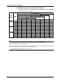
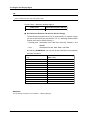
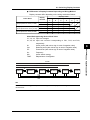
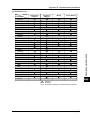
● Range Table (Table of Full Scales) – Rated Power
The table below shows the rated powers corresponding to combinations
of voltage and current ranges.
Current (A) Range
96031 Probe (50–1000 A)
Voltage
(V)
Range
1∅2W
96031 Probe (50–500 A)
96030 Probe (20–200 A)
96033 Probe (5–50 A)
5.000 A 10.00 A 20.00 A 50.00 A 100.0 A 200.0 A 500.0 A 1.000 kA
750.0 W 1.500 kW 3.000 kW 7.500 kW 15.00 kW 30.00 kW 75.00 kW 150.0 kW
150 V
1∅3W
3∅3W
3∅4W*
1∅2W
1.500 kW
1.500 kW
2.250 kW
1.500 kW
3.000 kW
3.000 kW
4.500 kW
3.000 kW
6.000 kW
6.000 kW
9.000 kW
6.000 kW
15.00 kW
15.00 kW
22.50 kW
15.00 kW
30.00 kW
30.00 kW
45.00 kW
30.00 kW
60.00 kW
60.00 kW
90.00 kW
60.00 kW
150.0 kW
150.0 kW
225.0 kW
150.0 kW
300.0 kW
300.0 kW
450.0 kW
300.0 kW
300 V
1∅3W
3∅3W
3∅4W*
1∅2W
1∅3W
3∅3W
3∅4W*
3.000 kW
3.000 kW
4.500 kW
2.250 kW
4.500 kW
4.500 kW
6.750 kW
6.000 kW
6.000 kW
9.000 kW
4.500 kW
9.000 kW
9.000 kW
13.50 kW
12.00 kW
12.00 kW
18.00 kW
9.000 kW
18.00 kW
18.00 kW
27.00 kW
30.00 kW
30.00 kW
45.00 kW
22.50 kW
45.00 kW
45.00 kW
67.50 kW
60.00 kW
60.00 kW
90.00 kW
45.00 kW
90.00 kW
90.00 kW
135.0 kW
120.0 kW
120.0 kW
180.0 kW
90.00 kW
180.0 kW
180.0 kW
270.0 kW
300.0 kW
300.0 kW
450.0 kW
225.0 kW
450.0 kW
450.0 kW
675.0 kW
600.0 kW
600.0 kW
900.0 kW
450.0 kW
900.0 kW
900.0 kW
1.350 MW
450 V
Phase
Lines
* Only for CW121
TIP
For reactive power, the same table applies but the units of measurement are different.
Units of reactive power: Var, kVar, MVar
If either or both of the VT and CT ratios are set to a value other than 1, and if the product of the following
formula exceeds 9999, the decimal point is incremented by one:
Rated power in table × VT ratio × CT ratio × 1.3
6-2
IM CW120-E
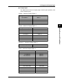
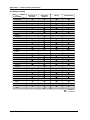
6.1 Ranges and Display Digits
● Display Digits
The tables below show the display digits, decimal point positions, and
units of measurement.
Voltage – Maximum Display Digits: 4
Range × VT Ratio (× 1.3)*
Decimal Point Position and Unit
150 to 999.9 V
999.9 V
1 to 9.999 kV
9.999 kV
10 to 99.99 kV
99.99 kV
100 to 999.9 kV
999.9 kV
1 to
4.5 MV
4.500 MV
6
Current – Maximum Display Digits: 4
Setting Ranges and Wiring Method
Range × CT Ratio (× 1.3)*
Decimal Point Position and Unit
5 to 9.999 A
9.999 A
10 to 99.99 A
99.99 A
100 to 999.9 A
999.9 A
1 to 9.999 kA
9.999 kA
10 to 99.99 kA
99.99 kA
100 to 999.9 kA
999.9 kA
1 to 9.999 MA
9.999 MA
10 MA
10.00 MA
Frequency – Maximum Display Digits: 4
Input Frequency
Decimal Point Position and Unit
40 to 70 Hz
70.00 Hz
Power – Maximum Display Digits: 4
Rated Power × VT Ratio × CT Ratio (× 1.3)* Decimal Point Position and Unit
975 to 999.9 W
999.9 W
1 to 9.999 W
9.999 W
10 to 99.99 W
99.99 W
100 to 999.9 W
999.9 W
1 to 9.999 kW
9.999 kW
10 to 99.99 kW
99.99 kW
100 to 999.9 kW
999.9 kW
1 to 9.999 MW
9.999 MW
10 to 99.99 MW
99.99 MW
100 to 999.9 MW
999.9 MW
1 to 9.999 GW
9.999 GW
10 to 99.99 GW
99.99 GW
100 to 999.9 GW
999.9 GW
1000 to 9999 GW
9999 GW
* Multiply by 1.3 only when the CT or VT ratio is a value other than 1.
IM CW120-E
6-3
6.1 Ranges and Display Digits
TIP
For reactive power, the same table as for the power applies but the units of measurement are different.
Units of reactive power: Var, kVar, MVar, GVar
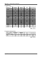
Power Factor – Maximum Display Digits: 4
Power Factor
Decimal Point Position and Unit
–1 to 1
1.000
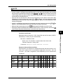
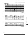
● Decimal Point Position and Unit for Electric Energy
The decimal point position and unit of measurement for electric energy
can be set via the screen (see Section 7.2.16, “Selecting Decimal Point
Position and Unit for Electric Energy”).
• Decimal point: Selectable from 000.000, 0000.00, 00000.0, and
• Unit:
000000
Selectable from Wh, kWh, MWh, and GWh
By selecting STANDARD, you can also let the CW120/121 automatically
set them as follows.
Rated Power × VT Ratio × CT Ratio
(× 1.3)*
1 to 9.999
10 to 99.99
100 to 999.9
1 to 9.999
10 to 99.99
100 to 999.9
1 to 9.999
10 to 99.99
100 to 999.9
1 to 9.999
10 to 99.99
100 to 9999
W
W
W
kW
kW
kW
MW
MW
MW
GW
GW
GW
Decimal Point Position and Unit for Electric energy
(Max. Count)
0.00 to 9999.99 Wh
0.0
to 99999.9 Wh
0.000 to 999.999 kWh
0.00 to 9999.99 kWh
0.000 to 999.999 kWh
0.00 to 9999.99 MWh
0.0
to 99999.9 MWh
0.000 to 999.999 MWh
0.00 to 9999.99 GWh
0.00 to 9999.99 GWh
0.0
to 99999.9 GWh
0
to 999999 GWh
* Multiply by 1.3 only when the CT or VT ratio is a value other than 1.
SEE ALSO
For the setting procedures, see Chapter 7, “Making Settings.”
6-4
IM CW120-E
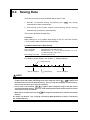
6.1 Ranges and Display Digits
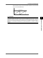
When the electric energy count has reached the maximum, the count will be
Power
reset to zero as illustrated below.
999.999 kWh
0
Time
WARNING
IM CW120-E
6-5
6
Setting Ranges and Wiring Method
When newly starting integrating power, clear the electric energy count (and the elapsed time of
integration). Otherwise, the electric energy count will be added to the previous value. For details
of how to clear the electric energy count, see Section 9.2.3, “Clearing Electric Energy Count,” or
Section 7.2.4, “Clearing Electric Energy Count and Resetting System,” in Chapter 7, “Making
Settings.”
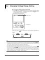
6.2 Changing Voltage Range Setting
● Procedure to Change Voltage Range Setting
(1) The
sign is displayed uppermost on the screen, under the voltage
range currently selected. To change the range, press the
the measurement screen is displayed.
key when
Voltage ranges
150V 300V 450V
V RANGE
V RANGE key
Each press of the
key changes the range selection sequentially as
follows:
150 V
300 V
450 V
Default: 150 V
TIP
• If a change to the range setting is incompatible with the conditions derived from other settings,
is displayed and the change is ineffective. First change other settings such as the current range, VT
ratio, CT ratio, and wiring method, then change the voltage range.
• The voltage range cannot be changed during continuous measurement.
• The voltage range cannot be changed when the electric energy count is not zero. Pressing the
key at this time causes
to appear on the screen (this will disappear and the measurement
screen will return when any key is pressed). Clear the electric energy count first. For details of how to
do this, see Section 9.2.3, “Clearing Electric Energy Count,” or Section 7.2.4, “Clearing Electric Energy
Count and Resetting System,” in Chapter 7, “Making Settings.”
6-6
IM CW120-E
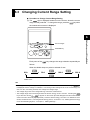
6.3 Changing Current Range Setting
● Procedure to Change Current Range Setting
(1) The
sign is displayed lowermost on the screen, above the current
range currently selected. To change the range, press the
the measurement screen is displayed.
key when
6
10A 20A 50A 100A 200A 500A 1000A
Current ranges
A RANGE
A RANGE key
Each press of the
follows:
key changes the range selection sequentially as
When the 96030 clamp-on probe is selected for use
20 A
50 A
100 A
200 A
Default: 20 A
TIP
• If a change to the range setting is incompatible with the conditions derived from other settings,
is displayed and the change is ineffective. First change other settings such as the current range, VT
ratio, CT ratio, and wiring method, then change the voltage range.
• The voltage range cannot be changed during continuous measurement.
• The voltage range cannot be changed when the electric energy count is not zero. Pressing the
key at this time causes
to appear on the screen (this will disappear and the measurement
screen will return when any key is pressed). Clear the electric energy count first. For details of how to
do this, see Section 9.2.3, “Clearing Electric Energy Count,” or Section 7.2.4, “Clearing Electric Energy
Count and Resetting System,” in Chapter 7, “Making Settings.”
IM CW120-E
6-7
Setting Ranges and Wiring Method
5A
6.3 Changing Current Range Setting
When the 96033 clamp-on probe is selected for use
5A
10 A
20 A
50 A
Default: 5 A
When the 96031 clamp-on probe is selected for use
50 A
100 A
200 A
500 A
Default: 50 A
When the 96032 clamp-on probe is selected for use
200 A
500 A
1000 A
Default: 200 A
● Selecting Clamp-on Current Probe to Be Used
The current ranges that can be selected vary with the clamp-on current
probe used. The probe selection can be changed from a setting screen.
Clamp-on Current Probe Models and Ratings
Clamp-on Current Probe Model
Setting
96033
50 A
5/10/20/50 A
Rating (Ranges)
96030
200 A
20/50/100/200 A
96031
500 A
50/100/200/500 A
96032
1000 A
200/500/1000 A
Default: 200 A
Procedure to Change Probe Selection
(1) Press the
key when the measurement screen is displayed. The
sign
screen switches to the setting item selection screen and the
appears in the lower left of the screen.
(2) Using the
keys, make the
mark (in the lower right) and its
current setting appear on the screen. Then, press the
key. The
number representing the currently selected clamp model flashes.
6-8
IM CW120-E
6.3 Changing Current Range Setting
MEAS/SET key
UP/DOWN/LEFT/RIGHT keys
MEAS/SET
ENTER
6
DISP
(3) Using the
keys, select the number corresponding to the
desired clamp-on current probe.
or
or
(4) Press the
key.
(5) Press the
key to return to the measurement screen. The range is
changed according to the new probe selected.
SEE ALSO
For details of the clamp selection, see Chapter 7, “Making Settings.”
TIP
• If a change to the clamp-on current probe selection is incompatible with the conditions derived from
other settings, the change is ineffective. First change other settings such as the voltage range, VT
ratio, CT ratio, and wiring method, then change the probe selection.
• The current probe cannot be changed during continuous measurement.
• The current probe cannot be changed when the electric energy count is not zero, and an attempt to
change causes
to appear on the screen (this will disappear and the measurement screen
will return when any key is pressed). Clear the electric energy count first. For details of how to do
this, see Section 9.2.3, “Clearing Electric Energy Count,” or Section 7.2.4, “Clearing Electric Energy
Count and Resetting System,” in Chapter 7, “Making Settings.”
IM CW120-E
6-9
Setting Ranges and Wiring Method
ENTER key
6.4 Changing Wiring Method Setting
l Procedure to Change Wiring Method Setting
(1) The
sign is displayed uppermost on the screen, above the wiring
method currently selected. To change the method, press the
key
when the measurement screen is displayed.
Wiring methods
WIRING
WIRING key
Each press of the
key changes the wiring method selection
sequentially as follows:
For CW120
1∅2W
1∅3W
3∅3W
Default: 3∅3W
TIP
• If a change to the wiring method setting is incompatible with the conditions derived from other settings, the change is ineffective. First change other settings such as the voltage range, current range,
VT ratio, and CT ratio, then change the wiring method.
• The wiring method cannot be changed during continuous measurement.
• The wiring method cannot be changed when the electric energy count is not zero. Pressing the
key at this time causes
to appear on the screen (this will disappear and the measurement
screen will return when any key is pressed). Clear the electric energy count first. For details of how
to do this, see Section 9.2.3, “Clearing Electric Energy Count,” or Section 7.2.4, “Clearing Electric
Energy Count and Resetting System,” in Chapter 7, “Making Settings.”
6-10
IM CW120-E
6.4 Changing Wiring Method Setting
For CW121
1∅2W
1∅3W
3∅3W
3∅4W
Default: 3∅3W
SEE ALSO
For details of the wiring methods, see Chapter 5, “Wiring.”
6
Setting Ranges and Wiring Method
IM CW120-E
6-11
Test Equipment Depot - 800.517.8431 - 99 Washington Street Melrose, MA 02176
FAX 781.665.0780 - TestEquipmentDepot.com
Chapter 7. Making Settings
7.1 Setting Items and Item Selection
● Setting Items
Before starting measurement, the following measurement condition and
data saving settings should be made as necessary.
Setting Item
Display Mark
1. Device number
2. Loading and saving of settings
3. Deletion of measured-data file and formatting of PC card
4. Clearance of electric energy count and resetting of system
5. Copying and clearance of backup memory
6. Date
7
7. Output interval
Making Settings
8. Integration start date and time
9. Integration stop date and time
10.Data saving to PC card
11.Communication device selection
12.Communication settings
13.VT ratio setting
14.CT ratio setting
15.Clamp-on current probe selection
16.Decimal point position and unit selections for electric energy
TIP
The Setting Check Sheet in the back of Operation Guide (IM CW120P-E) lists necessary settings and
their available selections. Use this sheet for grasping the setting conditions and for efficient setting on
site.
IM CW120-E
7-1
7.1 Setting Items and Item Selection
● Keys Used for Setting
The keys used for setting are described below.
Device number
MEAS/SET key
UP/DOWN/LEFT/RIGHT keys
MEAS/SET
ESC
ENTER
DISP
ENTER key
ESC key
key
Used to toggle the display between measurement and setting screens.
The
mark is displayed on a setting screen.
key
Used to fix a selection.
key
Used to cancel a setting. Pressing this key returns to the preceding
screen.
keys
Used to:
• Change the setting item displayed.
• Change a number.
• Change a setting.
keys
Used to:
• Change the setting item displayed.
• Select a digit.
• Change a setting.
7-2
IM CW120-E
7.1 Setting Items and Item Selection
● Setting Procedure
key. The display changes from the measurement screen
(1) Press the
to the screen for setting (the setting item selection screen) and the
sign appears in the lower left.
Device number setting screen
MEAS/SET key
7
ESC
ENTER
Making Settings
UP/DOWN/LEFT/RIGHT keys
MEAS/SET
DISP
ENTER key
ESC key
(2) Using the
keys, select the desired item, and then press the
key. Each time one of the
keys is pressed, the setting
item changes sequentially as follows.
or
or
To cancel a setting after pressing the
key, press the
key. The
(3) After making necessary changes to the settings, press the
key to
setting item selection screen then returns.
return to the measurement screen.
TIP
• The MEM (backup memory setting) is skipped if no data exists in the backup memory (and the MEM
mark is not lit on the measurement screen).
• The DEV (communication device) setting is skipped if your CW120/121 model has an RS-485 interface.
• The setting item that is selected by default when the screen changes from the measurement screen,
is the item selected last time the measurement screen was returned from a setting screen.
• In the electric energy measurement mode, the settings can be viewed only for checking and cannot
be modified.
IM CW120-E
7-3
7.2 Setting Each Item
7.2.1 Setting Device Number (
)
Description
The device number is used for identifying each power meter (CW120/121)
when monitoring a specific power with two or more CW120s and CW121s,
and also used as the device address when using RS-485 communication.
The device number consists of three digits. It is set to 001 by default and can
be set to any number from 001 to 999.
Procedure
(1) Using the
keys in the setting item selection screen, make the
mark and its corresponding setting appear on the screen. Then, press
key. The rightmost digit begins flashing.
the
Device Number Setting Screen
MEAS/SET key
UP/DOWN/LEFT/RIGHT keys
MEAS/SET
ESC
ENTER
DISP
ENTER key
ESC key
(2) Using the
flashes.
keys, select the digit to be changed. The selected digit
(3) Using the
keys, change the number of the selected digit.
key. The new device
(4) After making necessary changes, press the
number is then set and the setting item selection screen returns.
To cancel the changes, press the
key. The setting item selection
screen also returns.
7-4
IM CW120-E
7.2 Setting Each Item
7.2.2 Loading and Saving Settings
(
)
Description
Select
to load settings from a PC card.
to save settings to a PC card.
Select
The file number consists of three digits and can be set to any number from
000 to 029.
TIP
Name of setting file: WTHnnn.SET where nnn is the file number you set, from 000 to 029
Procedure
(1) Using the
keys in the setting item selection screen, make the
mark to appear on the screen. Then, press the
key.
begins flashing.
MEAS/SET key
UP/DOWN/LEFT/RIGHT keys
MEAS/SET
ESC
ENTER
DISP
ENTER key
ESC key
(2) Using the
keys, select
or
.
key to confirm the selection. A three-digit number
(3) Press the
appears on the lower row, allowing you to set the file number of the file to/
from which you want to save/load settings.
To cancel loading/saving, press the
key. The setting item selection
screen returns.
IM CW120-E
7
Making Settings
Loading/Saving Selection Screen
7-5
7.2 Setting Each Item
Loading
File Number Setting Screen for Loading
MEAS/SET key
UP/DOWN/LEFT/RIGHT keys
MEAS/SET
ESC
ENTER
DISP
ENTER key
ESC key
(4) Specify the file number in accordance with the steps below.
(5) Using the
keys, select the digit to be changed. The selected digit
flashes.
(6) Using the
keys, change the number of the selected digit.
(7) After making necessary changes, press the
key. The settings are
then loaded and the setting item selection screen returns.
You cannot select the file number of a file that does not exist. Selecting
such a file number returns to the screen for file number setting.
To cancel loading, press the
7-6
key. The screen in step (1) returns.
IM CW120-E
7.2 Setting Each Item
Saving
File Number Setting Screen for Saving
MEAS/SET key
UP/DOWN/LEFT/RIGHT keys
MEAS/SET
ESC
ENTER
7
DISP
ESC key
(4) Specify the file number in accordance with the steps below.
(5) The smallest file number within the unused numbers from 000 to 029 is
displayed.
(6) If the displayed number is fine, press the
key.
(7) If you want to specify a different file number, using the
the digit to be changed. The selected digit flashes.
keys, select
(8) Using the
keys, change the number of the selected digit.
(9) After making necessary changes, press the
key. The settings are
then saved and the setting item selection screen returns.
You cannot select a file number that has already been used. Selecting
such a file number returns to the screen for file number setting.
To cancel saving, press the
key. The screen in step (1) returns.
NOTE
• When the number of setting files residing in the inserted PC card has reached 30, you can no
longer save the settings. Attempting to save settings causes
to appear (this will
disappear and the previous screen will return when any key is pressed). Delete an unnecessary file or files and try saving again.
• The loading cannot be performed when the electric energy count and the integration time are not
zero. Attempting to load settings causes
to appear on the screen (this will disappear
and the measurement screen will return when any key is pressed). Clear the electric energy
count first. For details of how to do this, see Section 9.2.3, “Clearing Electric Energy Count,” or
Section 7.2.4, “Clearing Electric Energy Count and Resetting System,” in this chapter.
TIP
• When the PC card is full, the
formed.
sign is displayed on the screen and the saving cannot be per-
• Saving the settings when the communication device is set to a printer, prints the settings at the same
time.
IM CW120-E
7-7
Making Settings
ENTER key
7.2 Setting Each Item
7.2.3 Deleting Measured-data Files and Formatting PC Card (
)
Description
Select
to delete all the measured data saved in the PC card.
to format the PC card.
Select
Procedure
(1) Using the
keys in the setting item selection screen, make the
mark to appear on the screen. Then, press the
key.
begins flashing.
Measured-data Deletion Screen
PC Card Formatting Screen
MEAS/SET key
UP/DOWN/LEFT/RIGHT keys
MEAS/SET
ESC
ENTER
DISP
ENTER key
ESC key
(2) Using the
measured data or
(3) Press the
keys, select
if you want to delete the
if you want to format the PC card.
key. The selected action takes place and the setting item
selection screen returns.
To cancel the data deletion or formatting, press the
key. The setting
item selection screen also returns.
7-8
IM CW120-E
7.2 Setting Each Item
7.2.4 Clearing Electric Energy Count and Resetting System (
)
Description
Select
to clear the electric energy count (watt-hours).
to reset the system.
Select
Clearing the electric energy count means to reset all of the electric energy
count, elapsed time of integration, and regenerative energy count to zeros.
Resetting the system means to perform the same actions as clearing the
electric energy count and initialize the settings to the defaults, except for the
date, time, and device number.
Procedure
(1) Using the
keys in the setting item selection screen, make the
mark to appear on the screen. Then, press the
key.
begins flashing.
System Resetting Screen
MEAS/SET key
UP/DOWN/LEFT/RIGHT keys
MEAS/SET
ESC
ENTER
DISP
ENTER key
ESC key
(2) Using the
energy count or
(3) Press the
keys, select
if you want to clear the electric
if you want to reset the system.
key. The selected action takes place and the setting item
selection screen returns.
To cancel clearing the electric energy count or resetting the system, press
the
key. The setting item selection screen also returns.
NOTE
The electric energy count can also be cleared by simply pressing the
key for three seconds or
more in the measurement screen. For this, see Section 9.2.3, “Clearing Electric Energy Count.”
IM CW120-E
7-9
Making Settings
Electric Energy Count Clearance Screen
7
7.2 Setting Each Item
7.2.5 Copying and Clearing Backup Memory Contents (
)
Description
The CW120/121 have a memory for backing up the PC card. When the PC
card becomes full or is removed, data is saved to the backup memory. For
details, see Section 9.5, “Backup Memory.”
mark
When no data resides in the backup memory, namely, when the
is not displayed on the measurement screen, this setting item cannot be
called.
to copy the data in the backup memory to the PC card.
to delete the data from the backup memory.
Select
Select
Procedure
(1) Using the
keys in the setting item selection screen, make the
mark to appear on the screen. Then, press the
key.
appears and
flashes.
Copy Screen
Deletion Screen
MEAS/SET key
UP/DOWN/LEFT/RIGHT keys
MEAS/SET
ESC
ENTER
DISP
ENTER key
ESC key
(2) Using the
keys, select
the backup memory to the PC card or
if you want to copy the data in
if you want to delete the data
from the backup memory.
(3) Press the
key. The selected action takes place and the setting item
selection screen returns.
To cancel copying or deleting data, press the
key. The setting item
selection screen also returns.
7-10
IM CW120-E
7.2 Setting Each Item
7.2.6 Changing Date and Time (
)
Description
The CW120/121 have a clock, which is adjusted to the Japan standard time
by default (factory setting). To change the date and time, follow the
procedure below.
Procedure
(1) Using the
keys in the setting item selection screen, make the
mark and the current data and time settings appear on the screen.
key.
Then, press the
The day indication flashes.
Date and Time Change Screen
7
Making Settings
Year, month, and day
Hour:minute:second
MEAS/SET key
UP/DOWN/LEFT/RIGHT keys
MEAS/SET
ESC
ENTER
DISP
ENTER key
ESC key
(2) Using the
keys, select an item — year, month, day, hour, minute, or
second — you want to change. The selected item flashes.
(3) Using the
keys, change the value of the selected item. When
changing a number, pressing the
changes.
key continuously will make quick
(4) After making all necessary changes, press the
key. The date and
time settings are changed and the setting item selection screen returns.
To cancel the changes, press the
key. The setting item selection
screen also returns.
TIP
• For the year, set the last two digits. The range of the year setting is 00 to 99 (years 2000 to 2099).
• To make the changes effective, press the
broadcast or the like.
IM CW120-E
key synchronously with a time signal from a TV
7-11
7.2 Setting Each Item
7.2.7 Setting Output Interval (
)
Description
When saving (outputting) data in the electric energy measurement mode, the
interval of saving (outputting) data needs to be set. This output interval is set
to 30 minutes by default and can be selected from:
1, 2, 5, 10, 15, and 30 seconds,
1, 2, 5, 10, 15, and 30 minutes, and
1 hour.
Procedure
(1) Using the
keys in the setting item selection screen, make the
mark and the current interval setting appear on the screen. Then,
key. The current setting flashes.
press the
Output Interval Setting Screen
Interval
MEAS/SET key
UP/DOWN/LEFT/RIGHT keys
MEAS/SET
ESC
ENTER
DISP
ENTER key
ESC key
7-12
IM CW120-E
7.2 Setting Each Item
(2) Using the
keys, select the desired interval. The displayed
interval time changes sequentially as follows.
or
(30 min)
or
(1 hr)
(1 sec)
(2 sec)
(5 sec)
(10 sec)
(15 sec)
(15 min)
(30 sec)
7
(3) After selecting the desired interval, press the
key. The interval is
changed accordingly and the setting item selection screen returns.
Making Settings
(10 min)
(5 min)
(2 min)
To cancel the change, press the
also returns.
(1 min)
key. The setting item selection screen
NOTE
When setting the output interval to 2 minutes or less, note the following.
• Depending on the number of files residing in the PC card and the free space in it, the data at
the beginning may not be saved (for example, after approximately fifty-thousand samples have
been saved at one-second intervals). If this occurs,
appears on the screen and data
saving is stopped.
• Especially when setting the interval to 1 second, make sure that:
There is no file in the PC card (format the PC card to delete all files).
The PC card is inserted when starting the integration.
Do not remove the PC card during electric energy measurement.
Do not activate communication.
Do not perform excessive key actions.
Only if data saving to the PC card is enabled (see Section 7.2.10), data is saved to the PC card at
the specified interval.
IM CW120-E
7-13
7.2 Setting Each Item
7.2.8 Setting Integration Start Date and Time (
)
Description
There are three ways to start integration:
• Automatic starting at the specified time on the specified date
key for one second or more
• Manual starting by pressing the
• Remote starting by inputting a signal at the external control terminals
The following describes the start date and time setting for the first way.
Procedure
(1) Using the
keys in the setting item selection screen, make the
mark and the current settings of the start date and time appear on
the screen. Then, press the
key.
The day setting flashes.
Integration Start Date and Time Change Screen
Year, month, and day
Hour:minute:second
MEAS/SET key
UP/DOWN/LEFT/RIGHT keys
MEAS/SET
ESC
ENTER
DISP
ENTER key
ESC key
(2) Using the
keys, select an item — year, month, day, hour, minute, or
second — you want to change where the year, month, and day are shown
with superscripts y, m, and d to avoid confusion. The selected item
flashes.
(3) Using the
keys, change the value of the selected item. When
changing a number, pressing the
changes.
7-14
key continuously will make quick
IM CW120-E
7.2 Setting Each Item
(4) After making all necessary changes, press the
key. The start date
and time settings are changed and the setting item selection screen
returns.
To cancel the changes, press the
screen also returns.
key. The setting item selection
NOTE
Set a valid date and time.
• If the start date and time are set to before the current time, or if the specified start date and
time has passed before a start after setting, integration will start at the appropriate time determined by the output interval.
• If the start date and time are set to the same as the stop date and time or to later than the stop
date and time, the stop date and time are automatically set to the point after the output interval
from the start date and time.
• Resetting the system changes the integration start date and time to the current time.
For the year, set the last two digits. The range of the year setting is 00 to 99 (years 2000 to 2099).
SEE ALSO
For details of the start and stop of integration, see Section 9.2, “Starting and Stopping Integration.”
IM CW120-E
7-15
Making Settings
TIP
7
7.2 Setting Each Item
7.2.9 Setting Integration Stop Date and Time (
)
Description
There are three ways to stop integration:
• Automatic stopping at the specified time on the specified date
key for one second or more
• Manual stopping by pressing the
• Remote stopping by inputting a signal at the external control terminals
The following describes the stop date and time setting for the first way.
Procedure
(1) Using the
keys in the setting item selection screen, make the
mark and the current settings of the stop date and time appear on the
screen. Then, press the
key. The day setting flashes.
Integration Stop Date and Time Change Screen
Year, month, and day
Hour:minute:second
MEAS/SET key
UP/DOWN/LEFT/RIGHT keys
MEAS/SET
ESC
ENTER
DISP
ENTER key
ESC key
(2) Using the
keys, select an item — year, month, day, hour, minute, or
second — you want to change where the year, month, and day are shown
with superscripts y, m, and d to avoid confusion. The selected item
flashes.
(3) Using the
keys, change the value of the selected item. When
changing a number, pressing the
changes.
key continuously will make quick
(4) After making all necessary changes, press the
key. The stop date
and time settings are changed and the setting item selection screen
returns.
To cancel the changes, press the
screen also returns.
7-16
key. The setting item selection
IM CW120-E
7.2 Setting Each Item
NOTE
Set a valid date and time.
• You cannot set the stop date and time to the same time or before the start date and time.
• Resetting the system changes the integration stop date and time to 30 minutes after the current time (since the output interval is initialized to the default, 30 minutes).
TIP
For the year, set the last two digits. The range of the year setting is 00 to 99 (years 2000 to 2099).
SEE ALSO
For details of the start and stop of integration, see Section 9.2, “Starting and Stopping Integration.”
7
Making Settings
IM CW120-E
7-17
7.2 Setting Each Item
7.2.10 Enabling/Disabling Data Saving to PC Card (
)
Description
This determines whether to save the measured data during electric energy
measurement to the PC card.
Select
to enable (switch on) saving.
to disable (switch off) saving.
Select
By default, the saving is enabled (switched on).
Procedure
(1) Using the
keys in the setting item selection screen, make the
mark and the current on/off setting appear on the screen. Then, press
key.
the
The setting flashes.
Saving
Not Saving
MEAS/SET key
UP/DOWN/LEFT/RIGHT keys
MEAS/SET
ESC
ENTER
DISP
ENTER key
ESC key
(2) Using the
or
keys, select
if you want to disable saving.
(3) After making a change, press the
if you want to enable saving
key. The change is made
effective and the setting item selection screen returns.
To cancel the change, press the
key. The setting item selection screen
also returns.
NOTE
• When the saving is enabled (on), data is saved to the PC card in the output interval set (in
Section 7.2 7).
• When the saving is enabled (on), the
7-18
mark is displayed also in the measurement screen.
IM CW120-E
7.2 Setting Each Item
7.2.11 Selecting Communication Device (
)
Description
For RS-232 communication, you can select the device to connect to.
to connect to a personal computer.
Select
Select
to connect to a printer.
By default, connection to a personal computer is selected.
For RS-485 communication, only connection to a personal computer is
allowed, so this setting cannot be made.
Procedure
(1) Using the
keys in the setting item selection screen, make the
mark and the current device selection appear on the screen. Then,
press the
key. The selection flashes.
Selecting a Personal Computer
Selecting a Printer
7
Making Settings
MEAS/SET key
UP/DOWN/LEFT/RIGHT keys
MEAS/SET
ESC
ENTER
DISP
ENTER key
ESC key
(2) Using the
keys, select
personal computer or
if you want to connect to a
if you want to connect to a printer.
key. The change is made
(3) After making a change, press the
effective and the setting item selection screen returns.
To cancel the change, press the
also returns.
key. The setting item selection screen
NOTE
when a personal computer is selected, or
access to the corresponding device.
when a printer is selected, flashes during
SEE ALSO
For the computer connection, see Chapter 11, “Communication Functions.”
For the printer connection, see Section 12.2, “Using Optional Printer.”
IM CW120-E
7-19
7.2 Setting Each Item
7.2.12 Making Communication Settings (
)
Description
Follow the procedure below to set the baud rate, data bits, parity bit, and stop
bits to match the specifications of the device to connect to.
• Baud rate: 1200, 2400, 4800, 9600, or 19200 bps (9600 bps by default)
• Data bits: 7 or 8 (8 bits by default)
• Parity:
for no parity (default)
for even parity
for odd parity
• Stop bits: 1 or 2 (1 bit by default)
Procedure
(1) Using the
keys in the setting item selection screen, make the
mark and the current communication settings appear on the screen.
Then, press the
key.
The baud rate setting flashes.
Communication Setting Screen
Baud rate
Data bits-parity-stop bits
MEAS/SET key
UP/DOWN/LEFT/RIGHT keys
MEAS/SET
ESC
ENTER
DISP
ENTER key
ESC key
(2) If necessary, change the baud rate using the
changes sequentially as follows.
7-20
keys. The baud rate
IM CW120-E
Test Equipment Depot - 800.517.8431 - 99 Washington Street Melrose, MA 02176
FAX 781.665.0780 - TestEquipmentDepot.com
7.2 Setting Each Item
(3) Press the
key to move to the data bit setting. The leftmost number in
the lower row flashes. If necessary, change the data bit setting using the
keys.
(4) Press the
key to move to the parity bit setting. The middle number in
the lower row flashes. If necessary, change the parity bit setting using the
keys.
(5) Press the
key to move to the stop bit setting. The rightmost number in
the lower row flashes. If necessary, change the stop bit setting using the
keys.
key. The settings
(6) After making all necessary changes, press the
are changed accordingly and the setting item selection screen returns.
To cancel the changes, press the
screen also returns.
key. The setting item selection
• You can move between the baud rate, data bit, parity bit, and stop bit settings from one to another in
the reverse direction by using the
key.
• Resetting the system using a command via communication leaves the baud rate, data bit, parity bit,
and stop bit settings unchanged.
IM CW120-E
7-21
Making Settings
TIP
7
7.2 Setting Each Item
7.2.13 Setting VT Ratio (
)
Description
When installing an external voltage transformer (VT) and inputting the
secondary-circuit output of the VT to the CW120/121, setting the VT ratio
appropriately will display the reading correctly in the scale of the primary
circuit, namely, will perform scaling.
The VT ratio can be set from 1 to 10000 and is set to 1 by default.
When not using a VT, set the VT ratio to 1.
Whenever the VT ratio is set to a value other than 1, the
mark is displayed
even in the measurement mode.
Procedure
(1) Using the
keys in the setting item selection screen, make the
mark and the existing VT ratio setting appear on the screen. Then,
press the
key. The digit of the one place flashes.
VT Ratio = 1
VT Ratio = 10000
MEAS/SET key
UP/DOWN/LEFT/RIGHT keys
MEAS/SET
ESC
ENTER
DISP
ENTER key
ESC key
(2) Using the
flashes.
keys, select the digit to be changed. The selected digit
(3) Using the
keys, change the number.
(4) After making necessary changes, press the
key. The VT ratio
setting is changed accordingly and the setting item selection screen
returns.
To cancel the changes, press the
key. The setting item selection
screen also returns.
7-22
IM CW120-E
7.2 Setting Each Item
NOTE
• The VT ratio cannot be changed when the electric energy count or the elapsed time of integration is not zero. Attempting to change the ratio causes
to appear on the screen (this
will disappear and the measurement screen will return when any key is pressed). Clear the
electric energy count first. For details of how to do this, see Section 9.2.3, “Clearing Electric
Energy Count,” or Section 7.2.4, “Clearing Electric Energy Count and Resetting System,” in
this chapter.
• A setting that causes the product of [VT ratio × CT ratio × rated power × 1.3] to exceed 9999 GW
is not allowed.
TIP
Example of VT ratio setting:
When using a 2200-to-110 V transformer, the transformer ratio is 20:1. So, set the VT ratio to 20.
7
Displayed values:
Making Settings
Range of voltage reading: Voltage range × VT ratio
Range of current reading: Current range × CT ratio
Range of power reading:
IM CW120-E
Rated power × VT ratio × CT ratio
7-23
7.2 Setting Each Item
7.2.14 Setting CT Ratio (
)
Description
When installing an external current transformer (CT) and inputting the
secondary-circuit output of the CT to the CW120/121, setting the CT ratio
appropriately will display the reading correctly in the scale of the primary
circuit, namely, will perform scaling.
The CT ratio can be set from 1.00 to 10000.0 and is set to 1.00 by default.
When not using a CT, set the CT ratio to 1.00.
mark is
Whenever the CT ratio is set to a value other than 1.00, the
displayed even in the measurement mode.
Procedure
(1) Using the
keys in the setting item selection screen, make the
mark and the existing CT ratio setting appear on the screen. Then,
press the
key. The digit of the one place flashes.
CT Ratio = 1.00
CT Ratio = 10000.0
MEAS/SET key
UP/DOWN/LEFT/RIGHT keys
MEAS/SET
ESC
ENTER
DISP
ENTER key
ESC key
(2) Using the
flashes.
(3) Using the
keys, select the digit to be changed. The selected digit
keys, change the number.
(4) After making necessary changes, press the
key. The CT ratio
setting is changed accordingly and the setting item selection screen
returns.
To cancel the changes, press the
key. The setting item selection
screen also returns.
7-24
IM CW120-E
7.2 Setting Each Item
NOTE
• The CT ratio cannot be changed when the electric energy count or the elapsed time of integration is not zero. Attempting to change the ratio causes
to appear on the screen (this
will disappear and the measurement screen will return when any key is pressed). Clear the
electric energy count first. For details of how to do this, see Section 9.2.3, “Clearing Electric
Energy Count,” or Section 7.2.4, “Clearing Electric Energy Count and Resetting System,” in
this chapter.
• A setting that causes the product of [VT ratio × CT ratio × rated power × 1.3] to exceed 9999 GW
is not allowed.
TIP
Example of CT ratio setting:
When using a 100-to-5 A transformer, the transformer ratio is 20:1. So, set the CT ratio to 20.
7
Displayed values:
Making Settings
Range of voltage reading: Voltage range × VT ratio
Range of current reading: Current range × CT ratio
Range of power reading:
IM CW120-E
Rated power × VT ratio × CT ratio
7-25
7.2 Setting Each Item
7.2.15 Selecting Clamp-on Current Probe to Be Used ( )
Description
The following four models of clamp-on current probes can be connected to
the CW120/121.
Selectable Clamp-on Current Probes
Clamp-on Current Probe Model
Setting
96033
50 A
Rating (Ranges)
5/10/20/50 A
96030
200 A
2/50/100/200 A
96031
500 A
50/100/200/500 A
96032
1000 A
200/500/1000 A
Default: 200 A
Procedure
(1) Using the
keys, make the
mark (in the lower right) and its
current setting appear on the screen. Then, press the
key. The
number representing the currently selected clamp model flashes.
Selecting Clamp-on Current Probe to Be Used
MEAS/SET key
UP/DOWN/LEFT/RIGHT keys
MEAS/SET
ESC
ENTER
DISP
ENTER key
ESC key
(2) Using the
keys, select the number corresponding to the
desired clamp-on current probe. The number changes sequentially as
follows.
or
or
7-26
IM CW120-E
7.2 Setting Each Item
(3) After selecting the desired number, press the
key. The probe
selection is changed accordingly and the setting item selection screen
returns.
To cancel the change, press the
also returns.
key. The setting item selection screen
NOTE
The clamp-on current probe selection cannot be changed when the electric energy count or the
integration time is not zero. Attempting to change the selection causes
to appear on
the screen (this will disappear and the measurement screen will return when any key is pressed).
Clear the electric energy count first. For details of how to do this, see Section 9.2.3, “Clearing
Electric Energy Count,” or Section 7.2.4, “Clearing Electric Energy Count and Resetting System,” in this chapter.
7
TIP
IM CW120-E
7-27
Making Settings
A maximum of three clamp-on current probes may be connected though it varies with the wiring method;
probes having different ratings cannot be used at the same time. Namely, the clamp-on probes used at
the same time must be of the same model.
7.2 Setting Each Item
7.2.16 Setting Decimal Point Position and Unit of Electric Energy (
)
Description
You can set the decimal point position and unit of the electric energy
readings.
(default) when using the standard settings. Selecting the
Select
standard setting lets the CW120/121 power meter determine the decimal
point position and unit based on the product of [rated power × VT ratio × CT
ratio × 1.3] as follows.
Rated Power × VT Ratio × CT Ratio × 1.3 Decimal Point Position and Unit
1 to 9.999 W
0.00 to 9999.99 Wh
10 to 99.99
100 to 999.9
1 to 9.999
10 to 99.99
100 to 999.9
1 to 9.999
10 to 99.99
100 to 999.9
1 to 9.999
10 to 99.99
100 to 9999
W
W
kW
kW
kW
MW
MW
MW
GW
GW
GW
0.0
0.000
0.00
0.000
0.00
0.0
0.000
0.00
0.00
0.0
0
to 99999.9
to 999.999
to 9999.99
to 999.999
to 9999.99
to 99999.9
to 999.999
to 9999.99
to 9999.99
to 99999.9
to 999999
Wh
kWh
kWh
kWh
MWh
MWh
MWh
GWh
GWh
GWh
GWh
When specifying the desired decimal point position and unit, select:
• Decimal position setting from 000.000, 0000.00, 00000.0, and 000000.
• Unit from Wh, kWh, MWh, and GWh.
Procedure
(1) Using the
keys, make the
mark and its current settings
key.
or the number
appear on the screen. Then, press the
representing the currently set decimal point position flashes.
7-28
IM CW120-E
7.2 Setting Each Item
When Setting Neither Decimal Point Position Nor Unit Specifically
When Using Standard Settings
Representing “standard”
MEAS/SET key
UP/DOWN/LEFT/RIGHT keys
MEAS/SET
7
DISP
Making Settings
ESC
ENTER
ENTER key
ESC key
(1) Using the
(2) Then, press the
keys, select
.
key. The settings are changed accordingly and the
setting item selection screen returns.
To cancel the change, press the
key. The setting item selection screen
also returns.
IM CW120-E
7-29
7.2 Setting Each Item
When Setting Decimal Point Position Specifically
Setting Decimal Point Position
Move the decimal point using
the UP/DOWN/LEFT/RIGHT keys.
MEAS/SET key
UP/DOWN/LEFT/RIGHT keys
MEAS/SET
ESC
ENTER
DISP
ENTER key
ESC key
(1) Using the
keys, move the decimal point to the desired
position.
key. The setting is changed accordingly and the
(2) Then, press the
unit setting begins flashing.
To cancel the change, press the
also returns.
key. The setting item selection screen
The decimal point moves sequentially by the
keys as shown
below.
or
or
7-30
IM CW120-E
7.2 Setting Each Item
When Setting Unit Specifically
(1) After finishing changing the decimal point position setting, the unit setting
starts flashing to allow you to change it.
Setting Unit
Select the unit from Wh, kWh,
MWh, and GWh using the
UP/DOWN/LEFT/RIGHT keys.
MEAS/SET key
ENTER
Making Settings
ESC
7
UP/DOWN/LEFT/RIGHT keys
MEAS/SET
DISP
ENTER key
ESC key
(2) Using the
keys, change the unit.
(3) Then, press the
key. The setting is changed accordingly and the
setting item selection screen returns.
To cancel the change, press the
key. The setting item selection screen
also returns.
IM CW120-E
7-31
7.3 Setting Name of Measured-data File
When saving the measured data in the electric energy measurement mode,
you can set the name of the file to which measured data is to be saved.
File name = xxxxxxxx.CSV
Name (xxxxxxxx): Eight or less characters
Filename extension: Always CSV
Command: INTEgrate:STORe:FILEname Filename
When the file name is set, the set file name is displayed on the power meter’s
screen (called by pressing the
key) as shown below.
NOTE
• Once the file name is set, it remains the same even though integration is repeatedly performed,
namely, the measured data will be added to the same file.
• To reset the file name setting, reset the system or set the file name to ””.
• If the file name is not set, it will be assigned automatically.
SEE ALSO
For details of communication, see Chapter 11, “Communication Functions” and Chapter 12, “Communication Commands.”
7-32
IM CW120-E
Chapter 8. Instantaneous Value Measurement
8.1 Measuring Instantaneous Values
The CW120/121 power meters have two modes for measurement:
1. Instantaneous value measurement: Measures the rms voltages and
rms current of individual phases, and power, reactive power, power factor,
and frequency.
2. Electric energy measurement: In addition to the values in the
instantaneous value measurement mode, measures the electric energy.
Measurement is performed continuously and integration is started and
keys.
stopped by using the
This section describes instantaneous value measurement.
● Displayed Data
8
Displayed Name
Rms voltage
V
V1, V2, V3
(differs depending on the wiring method).
Rms current
A
A1, A2, A3
(differs depending on the wiring method).
Active power
W
W
Reactive power
Var
Var
Power factor
—
PF
Frequency
Hz
Hz (input frequency of V1)
Electric energy (watt-hours)
Wh
Wh
Elapsed time of integration
Hour: minute:second
Hour: minute
Hour
00:00:00TIME
0000:00TIME
00000hTIME
The display format changes over between the above
automatically depending on the elapsed time.
● Measurement Procedure
1. Perform safety checks
with reference to Chapter 3, “Precautions for Safe Measurement.”
2. Turn on the power to CW120/121
with reference to Chapter 4, “Connecting Power Supply and Turning
Power On/Off.”
3. Perform wiring
with reference to Chapter 5, “Wiring.”
4. Set the ranges and wiring method
with reference to Chapter 6, “Setting Ranges and Wiring Method.”
5. Set measurement conditions
with reference to Chapter 7, “Making Settings.”
6. Measure instantaneous values.
IM CW120-E
8-1
Instantaneous Value Measurement
Unit
Item
8.2 Switching Display Contents
Pressing one of the UP/DOWN/LEFT/RIGHT keys changes the display
contents in order. The sequence differs depending on the wiring method set.
For example, the sequence when the single-phase two-wire method is
chosen is shown below. Even for the unseen data items, the respective
calculations are performed internally.
Sequence of Display Contents Switching for Single-phase Two Wires
Measurement Screen
Using UP/DOWN/LEFT/RIGHT keys
Upper: Rms voltage
Lower: Rms current
or
or
Measurement Screen
Upper: Active power
Lower: Reactive power
Measurement Screen
Upper: Power factor
Lower: Frequency
Measurement Screen
Upper: Electric energy
Lower: Elapsed time of integration
8-2
IM CW120-E
8.2 Switching Display Contents
● Differences in Display Contents Depending on Wiring Method
Display contents differ depending on the wiring method as follows:
Displayed Item
Display
Position
Phase Wires
Single-phase two wires (1∅2W)
Single-phase three wires (1∅3W)
Three-phase three wires (3∅3W)
Three-phase four wires (3∅4W)
Upper row
Lower row
Upper row
Lower row
Upper row
Lower row
Screen Screen Screen Screen Screen Screen
1
2
3
4
5
6
V1
W
PF
Wh
A1
Var
Hz
TIME
V1
A1
W
PF
Wh
V2
A2
Var
Hz
TIME
V1
V3
A2
W
PF
Wh
V2
A1
A3
Var
Hz
TIME
3∅4W
1∅3W or 3∅3W
1∅2W
or
Screen 1
or
Screen 2
Screen 3
Screen 4
Screen 5
Screen 6
TIP
The active electric energy and elapsed time of integration are displayed also during instantaneous value
measurement.
IM CW120-E
8-3
8
Instantaneous Value Measurement
Name/Unit Appearing Next to Each Value
V1, V2, V3: Input rms voltages
A1, A2, A3: Input rms currents corresponding to CH1, CH2, and CH3,
respectively
W:
Active power (with minus sign in case of negative value)
Var:
Reactive power (with minus sign in case of negative value)
PF:
Power factor (with minus sign in case of negative value)
Hz:
Frequency
Wh:
Active electric energy
TIME:
Elapsed time of integration
8.3 Saving Data
There are two ways to save measured data to the PC card:
1. Manual, on-demand saving by pressing the
instantaneous value measurement
key during
2. Auto-saving at the preset output interval during electric energy
measurement (continuous measurement)
This section describes the former way.
Procedure
Pressing the
key when the measurement screen is displayed during
instantaneous value measurement causes a one-shot action of saving all the
measured values. (This action is referred to as manual saving.)
key. The file
(1) When the measurement screen is displayed, press the
number then appears on the screen and all the measured values are saved.
File Number Display upon Manual Saving
Saving-to-PC-card mark
Data record number
File number
SAVE key
SAVE
(2) Pressing the
key again saves the measured values again with the
data record number incremented but with the file number unchanged.
8-4
IM CW120-E
8.3 Saving Data
NOTE
• The file name will be given automatically.
• The file number is renewed in the following cases: (1) the data record number has exceeded
99; (2) the wiring method has changed; (3) the
or
actions have been carried out
in the setting screen; (4) the PC card is removed or a PC card is inserted; and (5) the power is
turned off once and then back on.
• Up to 30 files can be saved to a PC card (corresponding to file numbers from 000 to 029);
attempting to save too many files causes
to appear. This will disappear and the
measurement screen will return when any key is pressed. Delete an unnecessary file or files
and try saving again.
• If there is something wrong with the inserted PC card, data cannot be saved and
appears. (The measurement screen will return when any key is pressed.)
• When the PC card becomes full, the
mark appears and data will not be saved.
• Saving the measured data when the communication device is set to a printer, causes the
mark to flash and prints the data at the same time as the data saving.
File name = MWTHxxx.CSV
Name (xxx): The smallest, unused number from 000 to 029
Filename extension: Always CSV
Command: INTEgrate:STORe:FILEname Filename
Example of Saved, Measured Data
Shown below is an example of a measured-data file (that was saved in a PC
card) when opened from a spreadsheet application that has a CSV file
converter. (The field configuration varies depending on the measurement
conditions.)
CW12x
File Type
2
Measure
Mode
1
OUTPUT
DATE
OUTPUT
TIME
2001/11/11
10:10:00 0000/00/00
0:00:00
0:00:00
2001/11/11
10:15:00 0000/00/00
0:00:00
0:00:00
2001/11/11
10:21:00 0000/00/00
0:00:00
0:00:00
IM CW120-E
INTEG START INTEG START ELAPSED
V1 I1
DATE
TIME
TIME
P
Q PF F Wh(+) Wh(–)
8-5
8
Instantaneous Value Measurement
File Name and Format
Measured data are saved to a CSV format file and the file name (“MWTH”
followed by a number) is given automatically.
8.3 Saving Data
Header (measurement conditions)
CW12x:
Indicates the model.
File Type:
“2” indicates a file containing instantaneous values
measured.
Measure Mode:
“1” indicates electric energy measurement.
Fields of each data record
OUTPUT DATE:
Date of output
OUTPUT TIME:
INTEG START DATE:
Time of output
Integration start date
INTEG START TIME:
ELAPSED TIME:
Integration start time
Elapsed time of integration
(The order of measured value fields below shows an example for the
single-phase two-wire method.)
V1:
Rms voltage (value appearing with “V1” on meter screen)
I1:
P:
Rms current (value appearing with “A1” on meter screen)
Active power (value appearing with “W” on meter screen)
Q:
PF:
Reactive power (value appearing with “Var” on meter screen)
Power factor (value appearing with “PF” on meter screen)
F:
Wh(+):
Frequency (value appearing with “Hz” on meter screen)
Active electric energy (value appearing with “Wh” on meter
Wh(–):
screen)
Regenerative energy (not appearing on meter screen)
SEE ALSO
For details, see Appendix 3, “File Structures and Data Items Printed.”
8-6
IM CW120-E
8.4 Frequency Measurement
The frequency of voltage input V1 is presented as the measured frequency.
The frequency measurement is performed synchronously with the signal
input.
When the V1 level is less than 10% of the rated voltage, the integration cycle
is fixed to approximately 125 milliseconds.
Range of frequency measured: 45 to 65 Hz
Provision of Lowpass Filter
A lowpass filter with the cutoff frequency of 300 Hz is built into the frequency
measurement circuit for eliminating noise from the input signal and assuring
accurate frequency measurement.
8
Instantaneous Value Measurement
IM CW120-E
8-7
8.5 Sampling Cycle and Integration Cycle
Synchronously with the zero crossing signal for the input voltage V1, the time
period from when a cycle of zero-crossing begins until a cycle of zero crossing
occurs immediately next after a specified period (100 milliseconds) has
elapsed, is set to the integration cycle, and the rms voltage, rms current, and
power are calculated.
Sampling frequency: Approx. 10 kHz
Integration cycle: 120 ms
Frequency
measurement
input V1
(sine wave)
50 Hz
20 ms
Zero-crossing
signal
100 ms
Examples
Frequency (Hz)
Integration Cycle (ms)
Number of Waves
50
120
6
60
116.67
7
8-8
IM CW120-E
Test Equipment Depot - 800.517.8431 - 99 Washington Street Melrose, MA 02176
FAX 781.665.0780 - TestEquipmentDepot.com
Chapter 9. Electric Energy Measurement
9.1 Measuring Electric Energy
The CW120/121 power meters have two modes for measurement:
1. Instantaneous value measurement: Measures the rms voltages and
rms current of individual phases, and power, reactive power, power factor,
and frequency.
2. Electric energy measurement: In addition to the values in the
instantaneous value measurement mode, measures the electric energy.
Measurement is performed continuously and integration is started and
keys.
stopped by using the
This section describes electric energy measurement.
● Displayed Data
As the values measured and displayed, those related to active electric
energy are added to the values during instantaneous value measurement.
9
During Instantaneous Value Measurement
Electric Energy Measurement
Item
Displayed Name
Unit
Rms voltage
V
V1, V2, V3
(differs depending on the wiring method)
Rms current
A
A1, A2, A3
(differs depending on the wiring method)
Active power
W
W
Reactive power
Var
Var
Power factor
—
PF
Frequency
Hz
Hz (input frequency of V1)
During Electric Energy Measurement
Item
Active electric energy
Elapsed time of
integration
Unit
Wh
Hour:minute:second
Hour:minute
Hour
Displayed Name
Wh
00:00:00TIME
0000:00TIME
00000hTIME
The display format changes over between
the above automatically depending on the
elapsed time.
(Regenerative electric
energy)*
Wh
The values are not displayed on the screen,
but only saved.
* Stands for the integrated, reversal power flow.
IM CW120-E
9-1
9.1 Measuring Electric Energy
● Measurement Procedure
1. Perform safety checks
with reference to Chapter 3, “Precautions for Safe Measurement.”
2. Turn on the power to CW120/121
with reference to Chapter 4, “Connecting Power Supply and Turning
Power On/Off.”
3. Perform wiring
with reference to Chapter 5, “Wiring.”
4. Set the ranges and wiring method
with reference to Chapter 6, “Setting Ranges and Wiring Method.”
5. Set measurement conditions
with reference to Chapter 7, “Making Settings.”
6. Call the measurement screen
with reference to Chapter 8, “Instantaneous Value Measurement.”
7. Measure the electric energy (watt-hours).
NOTE
During integration (continuous measurement) or standby for integration, no settings can be
key for checking.
modified but they can be viewed by pressing the
9-2
IM CW120-E
9.2 Starting and Stopping Integration
9.2.1 Starting Procedures
There are three ways to start integration:
• Manual start:
Pressing the
key for one second or more starts
integration.
• Automatic start at the specified time on the specified date: Setting the
start date and time via the setting screen and
key puts the meter into the
pressing the
integration standby state. After this, when the
specified time is reached, integration begins.
• Remote start by external control signal: A signal input from the external
control terminals starts integration. For details, see
Section 9.6, “External Control Input/Output.”
IM CW120-E
9-3
9
Electric Energy Measurement
Manual Start
Press the
key for one second or more. Then, the
mark appears
on the screen, the LED status indicator immediately above the
key lights
up, and integration starts. If data saving to the PC card is enabled (see
Section 7.2.10), the file number of the file to which the data is to be saved is
displayed at the same time. After two seconds, the file number display
disappears and the measurement screen returns.
9.2 Starting and Stopping Integration
Display of File Number for Auto-saving
Integration mode mark
Saving-to-PC-card mark
File number
Upper: Rms voltage
Lower: Rms current
LED status indicator:
Lights up upon start of integration
START
&STOP
START&STOP key
Automatic Start at Specified Time on Specified Date
In this method, you set the integration start date and time via the setting
screen. For the setting procedure, see “Measurement Procedure” in Section
9.1, “Measuring Electric Energy,” and Section 7.2.8, “Setting Integration Start
Date and Time.”
● If Start Date and Time Are Set to Future Point of Time (Later than
Current Time)
Pressing the
key flashes the
mark (on the screen) and LED
status indicator. The file number of the file to which the data is to be saved
is displayed for approximately two seconds (only if data saving to the PC
card is enabled [see Section 7.2.10]), then the file number display
disappears and
appears, indicating that the power meter
has entered the integration standby state.
9-4
IM CW120-E
9.2 Starting and Stopping Integration
Display of File Number for Auto-saving
Integration mode mark
Saving-to-PC-card mark
File number
LED status indicator:
Flashes during integration standby state
&STOP
START&STOP key
When the specified time on the specified date has been reached, integration
begins.
mark flashes.
LED flashes.
Integration standby
LED status indicator
IM CW120-E
mark lights.
LED lights.
Integration in
progress
Integration start
date and time set
End of integration
9-5
Electric Energy Measurement
START
9
9.2 Starting and Stopping Integration
● If Start Date and Time Are Set to Past Point of Time (Earlier than
Current Time)
Pressing the
key flashes the
mark (on the screen) and LED
status indicator. The file number of the file to which the data is to be saved
is displayed for approximately two seconds (only if data saving to the PC
card is enabled [see Section 7.2.10]), then the file number display
disappears and
appears, indicating that the power meter
has entered the integration standby state.
Display of File Number for Auto-saving
Integration mode mark
Saving-to-PC-card mark
File number
LED status indicator:
Flashes during integration standby state
START
&STOP
START&STOP key
Integration will begin at an appropriate time determined from the output
interval set.
mark flashes.
LED flashes.
Integration standby
Integration start
date and time set
9-6
LED status indicator
mark lights.
LED lights.
Integration in
progress
Start of integration
(determined from output interval set)
End of
integration
IM CW120-E
9.2 Starting and Stopping Integration
TIP
• When setting the integration start date and time, consider the time period you need to finish all actions
for setting the date and time and putting the meter into the integration standby state. (The start date
and time may be passed before finishing the setting.)
• If the start date and time are set to later than (in the future) the stop date and time, the stop date and
time will be changed to the time after the start date and time for the output interval.
key
• The manual saving action takes precedence over the automatic start setting. Upon pressing the
for one second or more to start saving manually, the start date and time settings become ineffective.
• To reset the integration standby state, press any key to return to the measurement screen, and then
press the
key for one second or more. This will cause the
mark to disappear and the LED
status indicator to extinguish.
9.2.2 Stopping Procedures
There are three ways to stop integration:
• Manual stop:
key for one second or more stops
Pressing the
integration. (Use this method to abort integration.)
• Automatic stop at the specified time on the specified date: When the
and time settings are effective only when integration
has begun automatically at the start date and time set.)
• Remote stop by external control signal: A signal input from the external
control terminals stops integration. For details, see
Section 9.6, “External Control Input/Output.”
Manual Stop
Press the
key for one second or more. Then, the
mark
disappears from the screen, the LED status indicator immediately above the
key extinguishes, and integration stops.
Aborting Integration
To abort integration before the set stop date and time have been reached,
also press the
key for one second or more.
mark lights.
LED lights.
Integration
in progress
mark disappears.
LED extinguishes.
LED status indicator
Integration stop
date and time set
Press for one second
or more to abort
IM CW120-E
9-7
9
Electric Energy Measurement
specified time on the specified date set via the setting
screen is reached, integration stops. (The stop date
9.2 Starting and Stopping Integration
Automatic Stop at Specified Time on Specified Date
This is a method in which you set the integration stop date and time via the
setting screen. The stop date and time settings are effective only when
integration has begun automatically at the start date and time set. For the
setting procedure, see “Measurement Procedure” in Section 9.1, “Measuring
Electric Energy,” and Section 7.2.9, “Setting Integration Stop Date and Time.”
mark
When the set stop time and date have been reached, the
disappears from the screen, the LED status indicator immediately above the
key extinguishes, integration stops, and the screen changes as shown
below, indicating that integration has stopped.
Screen Showing End of Integration
Pressing any key returns to the screen for instantaneous value measurement.
TIP
• Set the stop date and time such that the period from the start to the end of integration is not shorter
than the output interval. Otherwise, only the data at the start and end times will be saved.
• Manually starting integration makes the stop date and time settings ineffective. You need to stop
integration manually in this case.
• If the start date and time are set to later than (in the future) the stop date and time, the stop date and
time will be changed to the time after the start date and time for the output interval.
• If the integration starts at a time after (in the future) the set stop date and time, the stop date and time
settings become ineffective. You need to stop integration manually in this case, too.
• As the stop date and time, you cannot set a time earlier than (in the past) the start date and time.
9-8
IM CW120-E
9.2 Starting and Stopping Integration
9.2.3 Clearing Electric Energy Count
There are two ways to clear the electric energy count and elapsed time of
integration:
1. In the measurement mode, press the
key for three seconds or more.
2. In the setting mode, choose the setting item for clearing the electric
energy count and resetting the system, and perform the specified setting
actions.
This section describes the former way. For the latter way, see Section 7.2.4,
“Clearing Electric Energy Count and Resetting System.”
Procedure
(1) When the measurement screen is displayed, press the
for three seconds or more. Then, the
flashes on the screen.
(escape) key
mark appears and
Electric Energy Count Clearance Screen
9
Electric Energy Measurement
ESC
ENTER
RESET
ENTER key
ESC (escape) key
(2) Press the
key. The electric energy count is cleared and the
measurement screen returns. To cancel, press the
measurement screen also returns.
IM CW120-E
key. The
9-9
9.3 Switching Display Contents
In the same way as during instantaneous value measurement, pressing one of
the
keys changes the display contents in order. The sequence
differs depending on the wiring method set. For example, the sequence when
the single-phase two-wire method is chosen is shown below. Even for the
unseen data items, the respective calculations are performed internally.
Sequence of Display Contents Switching for Single-phase Two Wires
Measurement Screen
Using UP/DOWN/LEFT/RIGHT keys
Upper: Rms voltage
Lower: Rms current
or
or
Measurement Screen
Upper: Active power
Lower: Reactive power
Measurement Screen
Upper: Power factor
Lower: Frequency
Measurement Screen
Upper: Electric energy
Lower: Elapsed time of integration
9-10
IM CW120-E
9.3 Switching Display Contents
● Differences in Display Contents Depending on Wiring Method
Each time one of the
change sequentially as follows:
keys is pressed, the display contents
Displayed Item
Display
Position
Phase Wires
Single-phase two wires (1∅2W)
Single-phase three wires (1∅3W)
Three-phase three wires (3∅3W)
Three-phase four wires (3∅4W)
Upper row
Lower row
Upper row
Lower row
Upper row
Lower row
Screen Screen Screen Screen Screen Screen
1
2
3
4
5
6
V1
W
PF
Wh
A1
Var
Hz
TIME
V1
A1
W
PF
Wh
V2
A2
Var
Hz
TIME
V1
V3
A2
W
PF
Wh
V2
A1
A3
Var
Hz
TIME
3∅4W
1∅3W or 3∅3W
1∅2W
or
Screen 1
IM CW120-E
or
Screen 2
Screen 3
Screen 4
Screen 5
Screen 6
9-11
9
Electric Energy Measurement
Name/Unit Appearing Next to Each Value
V1, V2, V3:
Input rms voltages
A1, A2, A3:
Input rms voltages corresponding to CH1, CH2, and CH3,
respectively
W:
Active power (with minus sign in case of negative value)
Var:
Reactive power (with minus sign in case of negative value)
PF:
Power factor (with minus sign in case of negative value)
Hz:
Frequency
Wh:
Active electric energy
TIME:
Elapsed time of integration
9.4 Saving Data
There are two ways to save measured data to the PC card:
1. Manual, on-demand saving by pressing the
instantaneous value measurement
key during
2. Auto-saving at the preset output interval during electric energy
measurement (continuous measurement)
This section describes the latter way.
Procedure
Make settings so as to enable data saving to the PC card (see Section
7.2.10), and the data will be saved automatically.
Conditions Required for Data Saving
Start of integration:
End of integration:
Output interval:
Activated at the set date and time.
Activated at the set date and time.
Selected from 1, 2, 5, 10, 15, and 30 seconds, 1, 2, 5, 10,
15, and 30 minutes, and 1 hour.
Enabled (switched on).
Data saving to PC card:
For details of these settings, see Chapter 7, “Making Settings.”
Output interval
1
Start of integration
2
3
4
Data saving
n
End of integration
NOTE
• Up to 30 files with automatically given names can be saved to a PC card (corresponding to file
numbers from 000 to 029); attempting to save too many files causes
to appear and
the data will be saved to the backup memory. The error code will disappear and the measurement screen will return when any key is pressed.
• If a PC card is not inserted,
appears when integration begins and data will be
saved to the backup memory. (The error code will disappear and the measurement screen will
return when any key is pressed.)
• When the PC card becomes full, the
memory.
mark appears and data will be saved to the backup
For details, see Section 7.2.5, “Copying and Clearing Backup Memory Contents,” and Section
9.5, “Backup Memory.”
9-12
IM CW120-E
9.4 Saving Data
File Name and Format
Data measured during electric energy measurement are saved to a CSV
format file and the file name (“AWTH” followed by a number) is given
automatically and can also be specified using a command via communication.
The file name can also be specified using a command via communication.
File name = AWTHxxx.CSV
Name (xxx): The smallest, unused number from 000 to 029
Filename extension: Always CSV
If data saving to the PC card is enabled, the file number of the file to which
data is to be saved will be displayed on the screen when starting integration.
Display When File Name Is Given Automatically
Integration mark
9
Saving-to-PC-card mark
Electric Energy Measurement
File number
Display When File Name Is Specified
Integration mark
Saving-to-PC-card mark
SEE ALSO
For details, see Section 7.3, “Setting Name of Measured-data File.”
IM CW120-E
9-13
9.4 Saving Data
Example of Saved, Measured Data
Shown below is an example of a data file saved to a PC card when it is
opened from a spreadsheet application that has a CSV file converter. (The
field configuration varies depending on the measurement conditions.)
CW12x
File Type
0
Measure
Mode
1
OUTPUT
DATE
OUTPUT
TIME
2001/12/01
09:10:00 2001/12/01
09:00:00
0:10:00
2001/12/01
09:20:00 2001/12/01
09:00:00
0:20:00
2001/12/01
09:30:00 2001/12/01
09:00:00
0:30:00
INTEG START INTEG START ELAPSED
V1 I1
DATE
TIME
TIME
P
Q PF F Wh(+) Wh(–)
Header (measurement conditions)
CW12x:
File Type:
Indicates the model.
“0” indicates a file containing values of integrated data
(saved automatically).
Measure Mode: “1” indicates electric energy measurement.
Fields of each data record
OUTPUT DATE:
OUTPUT TIME:
Date of output
Time of output
INTEG START DATE:
INTEG START TIME:
Integration start date
Integration start time
ELAPSED TIME:
Elapsed time of integration
(The order of measured value fields below shows an example for the singlephase two-wire method.)
V1:
Rms voltage (value appearing with “V1” on meter screen)
I1:
P:
Rms current (value appearing with “A1” on meter screen)
Active power (value appearing with “W” on meter screen)
Q:
PF:
Reactive power (value appearing with “Var” on meter screen)
Power factor (value appearing with “PF” on meter screen)
F:
Wh(+):
Frequency (value appearing with “Hz” on meter screen)
Active electric energy (value appearing with “Wh” on meter
Wh(–):
screen)
Regenerative energy (not appearing on meter screen)
SEE ALSO
For details, see Appendix 3, “File Structures and Data Items Printed.”
9-14
IM CW120-E
9.5 Backup Memory
The CW120/121 have a built-in memory for backing up the PC card and can
be used for saving data up to 3000 times. Data is saved to the backup
memory in the following cases:
mark appears).
• When the PC card becomes full (the
• The PC card is removed during integration.
When data resides in the backup memory, the
mark is displayed. (The
data stored in the backup memory is retained during power-off.)
The data in the backup memory is cleared whenever integration starts.
Namely, starting integration when previous data is retained in the backup
memory deletes it.
NOTE
When an attempt is made to save data to the backup memory more than 3,000 times,
appears and the saving action is aborted.
9
● When a PC Card Having Sufficient Free Space Is Inserted during
Integration
When a PC card is inserted, the data from that time on is saved to the PC
card with the same file name as before. Then, when integration ends, the
data stored in the backup memory will be copied to the bottom of the last
file (i.e., data is added within the last file) in the PC card. During this
is displayed on the screen and it will change
copying action,
to
, indicating that integration has ended.
CW120
Removing
PC card that has become full
Integrated data
File name:
AWTH005.CSV
Backup memory
File name:
AWTH005.CSV
Inserting New PC card
Data file AWTH005.CSV
File name:
AWTH005.CSV
Copy
IM CW120-E
9-15
Electric Energy Measurement
The data in the backup memory is processed as follows.
9.5 Backup Memory
● When a PC Card Having Sufficient Free Space Is Not Inserted during
Integration
Data is continuously saved to the backup memory. If integration ends
after the PC card has become full or when it is not inserted, you need to
carry out either of the procedures below.
If Data Is Needed
Follow the procedure below to copy the data from the backup memory to a
formatted, new PC card.
(1) Insert a new, formatted PC card.
(2) Press the
(3) Using the
key to call the setting item selection screen.
keys, select
(make the
mark appear).
(4) Press the
(5) Press the
key.
then flashes on the screen.
key again. The data is then copied from the backup
mark will
memory to the PC card with the same file name. The
disappear, indicating that the copy has finished and data in the backup
memory has been cleared.
(6) Press the
key to return to the measurement screen.
Screen for Copying Data
Screen for Copying Data
MEAS/SET key
UP/DOWN/LEFT/RIGHT keys
MEAS/SET
ENTER
DISP
ENTER key
SEE ALSO
Section 7.2.5, “Copying and Clearing Backup Memory Contents”
NOTE
If a file having the same file name resides in the PC card, the data is copied (added) to the bottom
of that file.
9-16
IM CW120-E
9.5 Backup Memory
If Data Is Not Needed
Follow the procedure below to clear the data in the backup memory.
(1) Press the
(2) Using the
key to call the setting item selection screen.
keys, select
(make the
mark appear).
(3) Press the
(4) Using the
key.
(5) Press the
(6) Press the
key. The data is then cleared from the backup memory.
key to return to the measurement screen.
then flashes on the screen.
keys, change
to
.
Screen for Clearing Data
MEAS/SET key
Electric Energy Measurement
UP/DOWN/LEFT/RIGHT keys
MEAS/SET
ENTER
9
DISP
ENTER key
SEE ALSO
Section 7.2.5, “Copying and Clearing Backup Memory Contents”
NOTE
Starting the next integration will also clear the data in the backup memory.
IM CW120-E
9-17
9.6 External Control Input/Output
9.6.1 Remote Control
Integration (continuous measurement) can be started and stopped remotely.
The external control input must be a 0/5 V (Low/High) level voltage signal or
an open/close (short-circuit) contact. The external control output is a 0/5 V
(Low/High) level voltage signal. Only the models with the RS-232 interface
have external control input/output terminals.
Input
While the external control input signal is at the low level or is closed,
integration (continuous measurement) is performed. While the external
control input signal is at the high level or is open, instantaneous value
measurement is performed.
Output
While integration (continuous measurement) is performed, the output is at the
low level. While instantaneous value measurement is performed, the output
is at the high level.
mark is displayed when integration is controlled by the external
The
control signal.
• Input Circuit
• Terminal Arrangement
+5 V
4.7 kΩ
100 Ω
H
100 pF
L
• Output Circuit
• Example of Input Signal Changes
Min. 30 sec
5 V (open)
100 Ω
H
0 V (closed)
Start
Start
L
Stop
Stop
Integration in progress
(continuous measurement)
9-18
IM CW120-E
9.6 External Control Input/Output
Remote integration start/stop control takes precedence over manual start/
stop and automatic start/stop at specified times. Remote control takes effect
even during the integration standby state and when a setting screen is
displayed. However, it is ineffective when integration has already begun and
is on.
•
Monitoring time:
A start-to-stop period must be at least 30 seconds long. Do not change
the input signal within 30 seconds.
•
•
Input levels
Low: 0.0 to 0.8 V
High: 2.0 to 5.0 V
Allowable voltage:
The allowable voltage for the input terminals is –0.5 to 5.5 V.
9.6.2 Controlling Multiple CW120s and/or CW121s
When performing measurement with multiple CW120s and/or CW121s, you
can synchronously start and stop integration in all the CW120s and CW121s
by connecting external control terminals.
Synchronously
Meter No. 1
Meter No. 2
Meter No. 3
Control signal
● Controlling Meter Nos. 2 and 3 by Control Signal of Meter No. 1
Meter No. 1
IM CW120-E
Meter No. 2
Meter No. 3
9-19
Electric Energy Measurement
● Connecting a Control Signal in Parallel to Control All Meters
9
9.6 External Control Input/Output
9.6.3 Wiring for Terminals
● Wiring for External Control Input/Output Terminals
With a flatblade screwdriver or the like, push in the rectangular dip
beneath each terminal hole and insert a peeled signal wire. Releasing the
screwdriver grips the wire.
signal wire
Flatblade screwdriver or the like
NOTE
• Do not apply a voltage exceeding the allowable voltage range (–0.5 to 5.5 V) to the control
signal input terminal. The input circuit may be damaged.
• Do not confuse the input terminal with the output terminal.
● Applicable Wires for Signal Wiring
•
Recommended wires:
Solid AWG 18 wires (1.0 mm diameter) or stranded 0.75 mm2 wires
•
Usable wires:
Solid AWG 26 to AWG 18 (0.4 to 1.0 mm diameter) wires
Stranded AWG 22 to AWG 20 (0.3 to 0.75 mm2 diameter) wires with
each strand thicker than 0.18 mm diameter
Standard peeling length: 10 mm
9-20
IM CW120-E
Test Equipment Depot - 800.517.8431 - 99 Washington Street Melrose, MA 02176
FAX 781.665.0780 - TestEquipmentDepot.com
9.7 Meter Actions upon Power Failure and
Recovery
The following describes the meter actions upon power failure and restoration
concerning data saving. None of the following actions upon power failure and
restoration takes place when a power failure has occurred during
instantaneous measurement.
● After Power Failure Occurred during Integration Standby State
•
If the power is restored before the preset integration start time:
is displayed and the meter enters the integration standby state.
Pressing any key returns to the measurement screen, and integration will
start when the preset date and time is reached.
•
If the power is restored after the preset integration start time:
is displayed and the meter starts integration immediately after
the power has been restored. Pressing any key returns to the
9
measurement screen.
● If Power Failure Has Occurred during Integration
If data saving to the PC card is enabled (see Section 7.2.10), the active
electric energy, regenerative energy, elapsed time of integration, and date
and time of the power failure are saved. If a power failure has occurred during
the saving action, it will be aborted and the data will be invalid. (This may
result in destruction of the file.)
After the power restoration, the date and time of the restoration are saved,
is displayed, and integration restarts in the same conditions as
before the power failure. Pressing any key returns to the measurement screen.
Power Restoration Display
IM CW120-E
9-21
Electric Energy Measurement
Power Restoration Display
9.7 Meter Actions upon Power Failure and Recovery
Example of Power Failure/Restoration Data
CW12x
File Type
0
Measure Mode
OUTPUT DATE
1
OUTPUT TIME
INTEG START DATE INTEG START TIME
2001/12/01
09:10:00
2001/12/01
POWER OFF
2001/12/01
09:15:00
POWER ON
2001/12/01
09:18:00
09:00:00
ELAPSED TIME
0:10:00
POWER OFF: “2001/12/01” and “09:15:00” indicates that a power failure
occurred at 09:15:00 on December 1, 2001.
POWER ON:
9-22
“2001/12/01” and “09:18:00” indicates that the power was
restored at 09:18:00 on December 1, 2001.
IM CW120-E
Chapter 10. PC Card
10.1 PC Card Specifications
The CW120/121 can save measured data and settings to a PC card as well as
read saved settings from a PC card to apply them. The PC card interface of
the CW120/121 complies with the following standards.
•
•
PCMCIA
Japan Electronic Industry Development Association (JEIDA)
Slots:
Card type:
Format:
One Type II slot
Flash ATA
MS-DOS
● PC Card Models Whose Operations Have Been Verified
• Flash ATA card
•
Model
Capacity
SDP3B-16
16 MB
Compact flash card
Supplier
Model
Capacity
SanDisk Corporation, Japan
SDCFB-16
16 MB
SDCFB-32
32 MB
SDCFB-64
64 MB
SDCFB-128
128 MB
10
PC Card
IM CW120-E
Supplier
SanDisk Corporation, Japan
10-1
10.2 Inserting and Removing PC Card
How to Insert a PC Card
To the PC card slot on the side of the CW120/121, insert a PC card with its
front side up and in the direction of the arrow on top.
PC card eject button
Front side of flash ATA card
How to Remove a PC Card
Depress the eject button next to the card slot.
The eject button may be one of two positions: depressed and popped-out.
(The figure above shows the depressed position.)
Drawn position:
Depressing the button unlocks the card. Pull to remove
the card.
Depressed position: Depressing the button changes the position to the
popped-out position. Depress the button again to
unlock the card, and then pull to remove the card.
NOTE
• Removing the PC card during access to it may destroy the saved files and damage the card
itself. Before removing the card, ensure that:
• Continuous measurement is not in progress.
• Access to the card is not in progress (the
mark is not flashing).
• For details of handling the card, see the documentation supplied with the card.
• When transporting the CW120/121, remove the PC card from the slot.
10-2
IM CW120-E
10.3 Storage Capacity
The time span of data that can be saved varies depending on the output
interval. The table below shows the approximate time spans over which data
can be saved to a PC card for a few cases where there is no other file residing
in the card. The numbers in parentheses indicate the PC cards’ capacities.
Output Interval
Guideline of Time Span of Data
1 second
Approx. 15 hours
1 minute
Approx. 3 months (16 MB), approx. 6 months (32 MB), at
least 1 year (63 MB or larger)
30 minutes
At least 1 year
NOTE
To ensure that data can be saved, delete all files from the PC card other than measured-data files
and setting files. Be careful that the total number of files in a card does not exceed 100.
10
PC Card
IM CW120-E
10-3
10.4 Formatting PC Card
The CW120/121 can format a PC card in MS-DOS format. Format the card
before using a newly purchased card, or to erase all files in the card.
Formatting a PC Card with CW120
(1) Insert the PC card in the slot.
key to call
(2) When the measurement screen is displayed, press the
the setting item selection screen.
(3) Select
(4) Press the
(i.e., make the
key.
flashes on the screen.
keys, select
(5) Using the
Data Deletion Screen
(6) Press the
(7) The
mark appear).
.
Formatting Screen
key.
mark flashes, indicating that access to the PC card is in
progress. When the mark stops flashing and disappears, the formatting
has finished.
(8) To return to the measurement screen, press the
key.
SEE ALSO
For details of the respective settings, see Section 7.2.3, “Deleting Measured-data Files and Formatting
PC Card,” in Chapter 7, “Making Settings.”
10-4
IM CW120-E
10.5 Saving and Loading from/to PC Card
● Saving Measured Data to PC Card
There are two ways to save measured data to a PC card:
1. Pressing the
key during instantaneous value measurement
2. Auto-saving at a preset interval during electric energy measurement
(continuous measurement)
Saving Data During Instantaneous Value Measurement
Press the
key when the measurement screen is displayed, and a oneshot action of saving all the measured values will take place. (This action is
referred to as manual saving.)
File name: MWTHxxx.CSV
000 to 029
Saving Data During Electric Energy Measurement
Set the output interval via the setting screen, and data will be saved at the
output interval thus set. (This action is referred to as auto-saving.)
NOTE
Ensure that data saving to PC card is enabled (see Section 7.2.10) if you want to save data during
electric energy measurement.
SEE ALSO
For details of the respective settings, see Chapter 7, “Making Settings.”
For details of data saving during instantaneous value measurement, see Section 8.3, “Saving Data.”
For details of data saving during electric energy measurement, see Section 9.4, “Saving Data.”
IM CW120-E
10
PC Card
File name: AWTHxxx.CSV
000 to 029
10-5
10.5 Saving and Loading from/to PC Card
● Saving and Loading Settings
Saving Settings
Select
in the setting item selection screen, select
file number, and then perform saving.
, specify the
File name: WTHxxx.SET
File number from 000 to 029
Loading Settings
Select
in the setting item selection screen, select
, specify the
file number of one of the setting files saved in the PC card, and then perform
loading.
File name: WTHxxx.SET
File number from 000 to 029
SEE ALSO
For details of the respective settings, see Section 7.2.2, “Loading and Saving Settings,” in Chapter 7,
“Making Settings.”
● Copying Data from Backup Memory
When data is saved during electric energy measurement, if the PC card
becomes full or if the card is removed, the measured data is saved to the
backup memory. This data contained in the backup memory can be copied to
a PC card.
SEE ALSO
For details of how to copy data from the backup memory, see Section 7.2.5, “Copying and Clearing
Backup Memory Contents.”
10-6
IM CW120-E
10.6 Interface with Personal Computer
Data saved in a PC card can be processed on a PC. You can process
measured data using a spreadsheet application and so on by inserting a PC
card containing measured data into the PC card slot of a PC. Even when a
PC card is left inserted in a CW120 or CW121, the measured data in the PC
card can be read from a PC and the setting data can be written from the PC
via RS-232* or RS-485* communication. (Specify which of the interfaces you
need, when ordering.)
SEE ALSO
• For details of communication, see Chapter 11, “Communication Functions,” and Appendix 2, “Communication Commands.”
• For details of the format of saved files, see Appendix 3, “File Structures and Data Items Printed.”
10
PC Card
IM CW120-E
10-7
Chapter 11 Communication Functions
11.1 RS-232
The RS-232 interface allows the CW120/121 to be connected to a PC or
printer.
● RS-232 Interface Specifications
Electromechanical specifications:
Topology:
Compliant with EIA RS-232
Point to point
Communication method:
Synchronization:
Full duplex
Asynchronous
Baud rate:
Start bits:
1200, 2400, 4800, 9600, 19200 bps
Fixed to 1 bit
Data bits:
Parity:
7 or 8 bits
Odd, even, or none
Stop bits:
Connector:
1 or 2 bits
Miniature DIN, 8 pins
Hardware handshake:
Whether to set CA (RTS) and CB
(CTS) to true or use them as control
Software handshake:
signals can be chosen.
Transmission/reception control by X-
Reception buffer length:
on and X-off signals is possible.
1024 bytes
11
The handshaking settings cannot be changed from the CW120/121. Modify the handshaking
settings in a setting file and load the file to the CW120/121.
● RS-232 Interface Connections
When connecting a CW120 or CW121 to a computer or printer via its RS232 interface, you need to make interface settings such as handshaking
methods, data transmission speed (baud rate), and data bit length to
match those settings in the computer. For details of these settings, see
the pages that follow.
As the interface cable, use one of the cables dedicated for the CW120/
121: the 91011 (with D-sub 9-pin connector for a PC), 91009 (with D-sub
25-pin connector for a PC) or 91010 (for a printer).
IM CW120-E
11-1
Communication Functions
NOTE
11.1 RS-232
Connector Pins and Assigned Signals
1
2
4
3
5
6
7
8
1. CTS (Clear To Send):
Input handshaking signal from the computer
used when transmitting data to the computer
2. RXD (Receive [rx] Data): Input data from the computer
3. RTS (Request To Send): Output handshaking signal to the computer
used when receiving data from the computer
4. TXD (Transmit [tx] Data): Output data to the computer
5-7.
Unused
8. GND (Signal Ground):
Signal ground
Directions of Individual Signals
The figure below shows the directions of the individual signals used in the RS232 interface.
Computer
RTS (Request To Send)
7
CTS (Clear To Send)
8
TXD (Transmit Data)
3
RXD (Receive Data)
2
CW120/121
Correspondences of Signal Abbreviations between RS-232 Standard,
CCITT Standard, and JIS (Japanese Industrial Standard)
Signal Names and Pin Assignment
11-2
Abbreviations
Pin No.
(in 9 Pins)
RS-232
CCITT
JIS
5
AB (GND)
102
SG
Signal Ground
3
BA (TXD)
103
SD
Transmit Data
2
BB (RXD)
104
RD
Receive Data
7
CA (RTS)
105
RS
Request To Send
8
CB (CTS)
106
CS
Clear To Send
Name
IM CW120-E
11.1 RS-232
● Allowable Combinations of Handshaking Methods
To assure data exchange via the RS-232 interface with a computer, both
devices must follow a predetermined procedure (may be decided between
both parties) by sending/receiving a series of electric signals. This series
of exchanged signals is called a handshake. The handshake to be used
may vary depending on the computer connected but must match the
handshake performed by the computer. The following types of
handshakes are possible with the CW120/121.
Possible Combinations of Handshaking Methods
Transmission Control
Reception Control
(Control of Data Transmission to Computer) (Control of Data Reception to Computer)
Software
Hardware
Software
Hardware
Handshake
Handshake
Handshake
Handshake
Sends X-off
Resets CA
When Data in (RTS) to False
Reception
When Data in
Quits
Quits T
Buffer Has
Reception
Transmission ransmission
Handshaking upon Receipt
Reached 3
Buffer Has
When CB
No
No
Method
Reached 3
of X-off;
(CTS)
Handshake Quarters of the
Handshake
Capacity;
Quarters of the
Restarts
Becomes
Sends X-on
Capacity; Sets
Transmission False; Restarts
When Data in
CA (RTS) to
upon Receipt Transmission
Reception
True When
of X-on
When It
Buffer Has
Data in
Becomes True
Decreased to a
Reception
Quarter of the
Buffer Has
Capacity
Decreased to
a Quarter of the
Capacity
When Selecting OFF/OFF
• Transmission Control
No handshake is performed between the CW120/121 and computer. The
CW120/121 handles the X-off and X-on codes from the computer as data
and ignores CTS (CS in JIS).
•
Reception Control
No handshake is performed between the CW120/121 and computer.
After the reception buffer inside the CW120/121 becomes full, the
overflowed data will be discarded. RTS (RS in JIS) is always true.
IM CW120-E
11-3
11
Communication Functions
OFF/OFF
XON/XON
XON/RS
CS/RS
11.1 RS-232
When Selecting XON/XON
• Transmission Control
A software handshake is performed between the CW120/121 and
computer. When the CW120/121 receives the X-off code from the
computer while transmitting data, the CW120/121 quits the transmission.
Then, when it receives the X-on code next, it restarts the transmission.
The CW120/121 ignores CTS (CS in JIS) from the computer.
•
Reception Control
A software handshake is performed between the CW120/121 and
computer. When the free space in the reception buffer decreases to 256
bytes, the CW120/121 transmits the X-off code to the computer. When
the free space in the reception buffer increases to 768 bytes, the CW120/
121 transmits the X-on code to the computer. RTS (RS in JIS) is always
true.
When Selecting XON/RS
• Transmission Control
A software handshake is performed between the CW120/121 and
computer. When the CW120/121 receives the X-off code from the
computer while transmitting data, the CW120/121 quits the transmission.
Then, when it receives the X-on code next, it restarts the transmission.
The CW120/121 ignores CTS (CS in JIS) from the computer.
•
Reception Control
A software handshake is performed between the CW120/121 and
computer. When the free space in the reception buffer decreases to 256
bytes, the CW120/121 resets RTS (RS in JIS) to false. When the free
space in the reception buffer increases to 768 bytes, the CW120/121 sets
RTS to true.
When Selecting CS/RS
• Transmission Control
A software handshake is performed between the CW120/121 and
computer. When the CW120/121 detects that CTS (CS in JIS) has
become false while transmitting data, the CW120/121 quits the
transmission. Then, when it detects that CTS has become true next, it
restarts the transmission. The CW120/121 handles X-on/X-off codes sent
from the computer as data.
•
Reception Control
A software handshake is performed between the CW120/121 and
computer. When the free space in the reception buffer decreases to 256
bytes, the CW120/121 resets RTS (RS in JIS) to false. When the free
space in the reception buffer increases to 768 bytes, the CW120/121 sets
RTS to true.
11-4
IM CW120-E
11.1 RS-232
Precautions for Reception Control
While a CW120 or CW121 is controlling a data reception by a handshake,
data may be sent from the computer even when the free space in the
reception buffer is less than 256 bytes. In this case, regardless of whether a
handshake for data reception is set, overflowed data will be discarded after
the reception buffer becomes full. After free space appears in the reception
buffer, data begins being stored to the buffer again.
1024 bytes
Used
Used
When performing a handshake, if the
free space in the buffer has decreased to
256 bytes because the internal data
256 bytes unused transfer is too slow, the reception stops.
768 bytes unused
Used
After the status above, when data was
transfer internally and the free space in
the buffer has increased to 768 bytes, the
reception restarts.
After the buffer has become full,
regardless of whether a handshake for
data receptions is set, overflowed data
will not be stored and will be discarded.
TIP
When developing the computer’s communication program, be careful about the data transmission rate
so that the reception buffer either in the CW120/121 or in the computer will not become full.
11
Communication Functions
IM CW120-E
11-5
11.2 RS-485
The RS-485 interface allows multiple CW120s and CW121s to be connected
for remote monitoring.
● RS-485 Interface Specifications
Electromechanical specifications: Compliant with EIA RS-485
Topology:
Multidrop
Communication method:
Synchronization:
Half duplex
Asynchronous
Baud rate:
Start bits:
1200, 2400, 4800, 9600, 19200 bps
Fixed to 1 bit
Data bits:
Parity:
7 or 8 bits
Odd, even, or none
Stop bits:
Connector:
1 or 2 bits
4 screw terminals (M3)
Hardware handshake:
Software handshake:
Not available
Not available
Error detection:
Reception buffer length:
2-byte simple summation checksum
1024 bytes
Maximum transmission distance: 1.2 km (when using shielded cable
containing 2 twisted pairs of AWG 24
conductors)
Terminating resistor:
11-6
Approx. 120Ω built-in
IM CW120-E
11.2 RS-485
● RS-485 Interface Connections
See the figure below for the wiring of RS-485 cables (in two-wire method)
to connect to a personal computer. When using the RS-232 port of the
PC, you need an RS-232/RS-485 converter.
PC
RS-232
RS-232/RS-485
converter
Example: Yokogawa M&C ML1 converter
Terminating resistor: On
Terminating resistor: On
CW120/121
CW120/121
CW120/121
11
Communication cable
Communication cable
Up to 31 meters
IM CW120-E
+:
SD +(send data) / RD +(receive data)
–:
TM:
SD –(send data) / RD –(receive data)
Terminating resistor (short-circuiting with the + terminal switches on
SG:
the terminating resistor).
Signal ground
11-7
Communication Functions
Pair
11.2 RS-485
● Device Address
A device address needs to be assigned to each device on an RS-485
network. The device number set in each CW120/121 is identified as the
device address.
SEE ALSO
For device address setting, see Section 7.2.1, “Setting Device Number,” in Chapter 7, “Making Settings.”
NOTE
The device number must be unique within the same system for correct communication.
● Cable Used
Use shielded cables containing 2 twisted pairs of AWG 24 conductors.
WARNING
Turn off the power when performing wiring for the terminals to avoid electric shock.
11-8
IM CW120-E
11.3 Data Format
The serial interface of the CW120/121 performs asynchronous transmission.
In an asynchronous transmission, each character is carried in such a way that
7 or 8 data bits are preceded by a start bit and followed by a parity bit
(optional), and 1 or 2 stop bits in order (see also the figure below).
Idle state of line
Puts the line back
to idle state
(dashed line)
or sends start bit
(solid line).
1 character
Data bits
(7 or 8 bits)
Start bit
Parity bit: Odd,
even, or none
Stop bit
(s)
1
1 or 2
2
11
Communication Functions
IM CW120-E
11-9
Test Equipment Depot - 800.517.8431 - 99 Washington Street Melrose, MA 02176
FAX 781.665.0780 - TestEquipmentDepot.com
Chapter 12. Auxiliary Functions
12.1 Convenient Functions
● Clock
The CW120/121 have a built-in clock, which is adjusted to the Japan
standard time by default (factory setting). The date and time display
formats are YYyMMmDDd (YY is the last two digits of the year) and
hh:mm:ss, as shown below. The accuracy of the clock is ±100 ppm
(typical).
Date and Time Setting Display
Year, month, day
Hour : minute : second
To change the date and time, use the setting screen.
SEE ALSO
For clock adjustment, see Section 7.2.6, “Changing Date and Time,” in Chapter 7, “Making Settings.”
● Backlight for LCD
key.
You can turn on and off the backlight for the LCD by pressing the
When no key actions have been performed for 10 minutes or longer, the
● Key Lock
key for three seconds or more locks the keys and causes
Pressing the
the
(key lock) mark to appear on the screen.
To unlock, press the
unlocked and the
key for three seconds or more. The keys are
(key lock) mark disappears from the screen.
TIP
Only the
IM CW120-E
key is usable during the key lock state.
12-1
Auxiliary Functions
backlight is turned off automatically.
12
12.1 Convenient Functions
● Clearance of All Settings and Data
Keep pressing the
and
keys and turn on the power switch, then all
settings* will be initialized to the defaults, and the active electric energy,
regenerative energy, elapsed time of integration, and data in the backup
memory will be cleared.
* Except the date, time, and device number
Procedure
Hold down the
and
keys and turn on the power switch. Keep pressing
the
and
keys until the model number appears on the screen.
Meter Actions
All LCD segments light up, and then the model number and version appear.
Model and Version Display Screen
Upper: Model number
Lower: Version number
Power switch
START
&STOP
ESC
ESC key
START&STOP key
ALL CLEAr appears on the screen, and then the measurement screen is
displayed.
All Clear Screen
Measurement Screen
Upper: Rms voltage
Lower: Rms current
12-2
IM CW120-E
12.2 Using Optional Printer
Connecting an optional printer allows you to print measured data and
settings. The printer can be connected only to a model with the RS-232
interface.
● Printer Specification
Model:
Yokogawa M&C 97010 (Seiko Instruments DPU-414 printer)
Specifications:
Printing method:
Number of columns to print:
Character presentation:
Print speed:
Paper width:
Thermal serial dot printing
80
9x7 dots
52.5 mm/s
112 mm
● Connection
Use the RS-232 port.
Printer cable: Model 91010
1. Turn off the power to the printer. (The power lamp turns off.)
2. Connect the printer to the CW120/121 as shown in the figure below.
Printer
12
Auxiliary Functions
Power switch
Online switch
Serial port of printer (9 pins)
Printer cable (91010)
IM CW120-E
12-3
12.2 Using Optional Printer
● Checking Printer Settings
1. Keep pressing the Online switch of the printer and turn on the power.
Then, the printer settings are printed in English.
2. Check that the initial settings, as shown in parentheses inside the tables
below, are left.
Printer Initial Settings (DIP Switch Settings)
DIP SW-1
Setting
Item
ON
OFF
1 (OFF)
2 (ON)
Input type
Printing speed
Parallel
High
Serial
Low
3 (ON)
4 (OFF)
Auto-loading
CR or CR/LF
Enable
CR/LF
Disable
CR
5 (ON)
6 (OFF)
Setting command
Enable
Disable
7 (ON)
8 (ON)
Printing density = 100%
ON
OFF
DIP SW-2
Setting
Item
1 (OFF)
2 (ON)
Print mode
40 columns
Backup of user-defined characters Enable
80 columns
Disable
3 (ON)
4 (ON)
Character type
Character of zero
Special
∅
5 (ON)
6 (ON)
7 (ON)
8 (ON)
Normal
0
Encoding character set = Japanese
DIP SW-3
Setting
Item
ON
OFF
1 (ON)
Data bits
8 bits
7 bits
2 (ON)
3 (ON)
Parity (use/not use)
Parity (even/odd)
Not use
Odd
Use
Even
4 (OFF)
5 (OFF)
Flow control
H/W BUSY
XON/XOFF
6 (ON)
7 (ON)
Baud rate = 9600 bps
8 (ON)
3. Turn off the power to the printer.
12-4
IM CW120-E
12.2 Using Optional Printer
TIP
• For details of how to change the printer settings, see the documentation supplied with the printer.
• If the characters printed with the print mode selection in DIP SW-2 set to 80 columns (OFF) are too
small to read, change the setting to 40 columns (ON).
● Setting in CW120/121
When using a printer, a setting needs to be made also in the CW120/121.
Procedure
With reference to Section 7.2.11, “Selecting Communication Device,” in
Chapter 7, “Making Settings,” select a printer as the communication device.
Either a printer or personal computer can be connected via the RS-232
interface; select a printer when connecting to a printer.
Selecting a Personal Computer
Selecting a Printer
MEAS/SET key
ENTER
Auxiliary Functions
UP/DOWN/LEFT/RIGHT keys
MEAS/SET
ESC
12
DISP
ENTER key
ESC key
The
IM CW120-E
mark flashes on the screen during access to the printer.
12-5
12.2 Using Optional Printer
● Example of Printout
For instantaneous value measurement with 1(2W wiring method
2001/12/01
Instantaneous
values
Electric
energies
11:00:00
Integration start time
2001/12/01
10:00:00
Elapsed time
1:00:00
V1
: 110.0
I1
: 30.00
P
: 2.850
Q
: 1.664
PF
: 0.860
F
: 50.00
+Wh
: 889.20
-Wh
:
0.00
P: Active power
Q: Reactive powery
Time of output
Integration start
time
Elapsed time of
integration
V
A
kW
kVar
Hz
KWh
KWh
PF: Power factor
F: Frequency
SEE ALSO
For print data, see Appendix 3, “File Structures and Data Items Printed.”
TIP
The printout above is an example when the print mode is set to 40 columns (ON) in DIP SW-2. See the
DIP switch settings described on the page before the previous one.
12-6
IM CW120-E
Chapter 13. Troubleshooting
13.1 Corrective Measures in Case of
Failure
This section describes corrective measures in case a failure occurs with the
CW120 or CW121.
If the meter does not operate properly after taking the corrective measures
shown in the table below or any other failure that is not covered in this section
occurs, contact the vendor from which you purchased the instrument.
If an error code is displayed, refer to Section 13.2, “Error Codes.”
Problem
Things to Check
1. The meter cannot be turned
on.
• Check that the power cord is firmly plugged into the power outlet.
• Check that you are not using power outside the allowable power
supply voltage.
• If neither of the above applies, the built-in fuse may have blown.
Users are not authorized to replace a built-in fuse by themselves.
Contact the vendor from which you purchased the instrument.
2. The settings are initialized
when the power is turned on.
• If any one of the following error codes appears during the self-test
after a power-on, the backup battery may have run flat.
,
Users are not authorized to replace the backup battery by
themselves. Contact the vendor from which you purchased the
instrument.
The life of the backup battery is about 10 years.
3. Measurement values are
erroneous.
• May be affected by noise. Check the installation environment.
• Check that the measuring probes and the clamps are connected
correctly.
• Check that the ambient temperature and humidity are within the
allowable ranges.
4. No key action is possible.
• Check that the
(key lock) mark is not displayed on the screen.
• Some settings such as ranges can be changed only when the
electric energy values and elapsed time of integration are zeros.
Clear the integrated values.
5. Data cannot be saved to the
backup memory.
• Turn the power off and back on again. In some cases, the initial
self-test may correct the problem.
• A power failure might have occurred when the memory was being
accessed. Clear the backup memory contents via the setting
screen. Note that this loses data saved in the backup memory.
6. The meter cannot be
controlled through the serial
interface.
• Check that the communication parameters are set correctly for
both the computer and meter.
• Check that the correct type of cable is used for the intended
application.
7. An error code appears during • There is an error in the hardware. Contact the vendor from which
the self-test.
you purchased the instrument.
IM CW120-E
13-1
Troubleshooting
,
13
13.2 Error Codes
Error Code
Description
Error in SRAM with battery backup
EEPROM has been initialized.
Checksum error of EEPROM
Illegal data in EEPROM
Failure in writing to EEPROM
RTC has been initialized.
Error in RTC
Error in PC card controller
Settings have been initialized.
Illegal settings
Failure in writing to PC card
Failure in reading from PC card
Maximum number files in PC card exceeded
A PC card other than a flash ATA card is inserted.
PC card not yet formatted
A PC card not supported is inserted.
Failure in deleting a measured-value file
Failure in saving the setting file
Failure in loading the setting file
PC card-related error other than above
Data in internal memory exceeds the capacity.
Failure in saving measured data within output interval
The electric energy value or elapsed time of integration is not zero. No
change to setting allowed.
The product of [rated power × VT ratio × CT ratio × 1.3] exceeds 9999 GW.
To return to the measurement screen from the error display, press any key.
13-2
IM CW120-E
Chapter 14. Specifications
14.1 Specifications of CW120/121
(1) Inputs
Item
Input type
Voltage Inputs
Resistive potential division
Ratings (ranges)
CW120
Phase lines
CW121
Input
resistance
CW120
CW121
Current Inputs
Clamp sensing
96033 clamp-on probe: 5, 10, 20, 50 A
96030 clamp-on probe: 20, 50, 100, 200 A
150, 300, 450 V
96031 clamp-on probe: 50, 100, 200, 500 A
96032 clamp-on probe: 200, 500, 1000 A
Single-phase two wires, single-phase three wires, three-phase three wires
Single-phase two wires, single-phase three wires, three-phase three wires,
three-phase four wires
Approximately 1.5 MΩ
Approximately 1.3 MΩ
96033 clamp-on probe: 130 Arms
96030 clamp-on probe: 250 Arms
96031 clamp-on probe: 625 Arms
96032 clamp-on probe: 1000 Arms
Maximum allowed
continuous input
495 Vrms
A/D conversion
Simultaneous voltage/current input conversion, 12-bit resolution
(2) Measurement Functions
Item
Method
Frequency range
Effective input range
Lower limit
Display range
Upper limit
Temperature coefficient
Display update period
IM CW120-E
Approximately 1 second
14-1
Specifications
Crest factor
Voltage
Current/Active Power
Digital sampling
45 to 65 Hz (reciprocal method), detected from V1 input
150 or 300 V range: 2 for rated input
3 for rated input
450 V range: 1.56 for rated input
10% to 110% of each rated range
1.5 V for all rated ranges
0.4% of each range
130% of each rated range for all ranges
other than 450 V
130% of each rated range
110% of rated range for 450-V range
±0.05% of rng (range)/°C
±0.07% of rng (range)/°C
(including clamp-on probe)
14
14.1 Specifications of CW120/121
(3) Instantaneous Value Measurement
Measured parameters
Rms voltage (V), rms current (A), active power
(W), frequency (Hz)
Measurement accuracy At power factor = 1 (including clamp-on probes)
Voltage
±(0.3% rdg + 0.2% rng)
Current and active power
±(0.8% rdg + 0.4% rng) with probe 96030, 96031,
or 96033
±(1.2% rdg + 0.8% rng) with probe 96032
Frequency
Calculated parameters
±(0.1% rdg + 1 dgt)
Reactive power (Var), power factor
Calculation accuracy
Power factor effects
(Value calculated from measurement) ± 1 dgt
±1.0% rng cosφ = ±0.5 (relative to power factor 1)
with probe 96030
±2.0% rng cosφ = ±0.5 (relative to power factor 1)
with probe 96031, 96032, or 96033
±1.0% rng sinφ = ±0.5 (relative to reactive factor 1)
Reactive factor effects
with probe 96030
±2.0% rng sinφ = ±0.5 (relative to reactive factor 1)
with probe 96031, 96032, or 96033
(4) Equations
Rms voltage
1
T
Vrms =
T
0
2
v(t) dt =
1
T
T
1
T
T
v(t)
2
t=0
Rms current
1
T
Arms =
T
0
2
i(t) dt =
i(t)
2
t=0
Active power
P=
1
T
T
0
v(t) ~ i(t)dt =
1
T
T
v(t) ~ i(t)
t=0
Single-phase three wires (1ø3W) or three-phase
three wires (3ø3W): ∑P = P1 + P2
Three-phase four wires (3ø4W): ∑P = P1 + P2 +P3
v(i), i(t): Input signals
T: One cycle of input signal
14-2
IM CW120-E
14.1 Specifications of CW120/121
Reactive power and power factor
Reactive Power (Note 1)
((VA) 2 –
P2)
Apparent Power
1∅2W
Q=
1∅3W
Q i=
((VAi) 2 – Pi 2 )
i=1, 2
ΣQ=Q1+Q2
VAi=Vi × Ai
i=1, 2
ΣVA=VA1+VA2
3∅3W
Q i=
((VAi) 2 – Pi 2 )
i=1, 2
ΣQ=Q1+Q2
VAi=Vi × Ai
i=1, 2
ΣVA= 3/2(VA1+VA2)
Q i=
((VAi) 2 – Pi 2 )
i=1, 2, 3
ΣQ=Q1+Q2+Q3
VAi=Vi × Ai
i=1, 2, 3
ΣVA= VA1+VA2+VA3
3∅4W
VA=V × A
Power Factor (Note 2)
P / VA
ΣP / ΣVA
Calculation The rated value depends
range
on the voltage and current
ranges.
The rated value depends on
the voltage and current ranges.
Display
resolution
Only calculated internally;
±1.000
not displayed nor saved as data.
Same as active power
–1 to +1
Note 1: For distorted or unbalanced wave inputs, there may be discrepancies between the CW120/121 and other
instruments that operate based on different measurement principles.
Note 2: The plus/minus sign is displayed by multiplying the polarity obtained based on the varmeter method.
(5) Electric Energy Measurement
Measured parameters
Measurement accuracy Measurement accuracy for active power ±1 dgt
(with standard settings)
Integration function settings
Start/stop
Manual, specified time, external trigger (remote
Output interval
control)
Can be selected from 1, 2, 5, 10, 15, and 30
seconds, 1, 2, 5, 10, 15, and 30 minutes, and 1
hour.
Display digits
IM CW120-E
Automatic decision based on the rated power.
The maximum resolution can be set.
14-3
Specifications
Active electric energy, regenerative electric
energy (not displayed, only saved as data)
14
14.1 Specifications of CW120/121
(6) Display Functions
Display screen
Backlit segmented LCD
Maximum display digits 4 digits for data other than electric energy
6 digits for electric energy
Ranges (ratings)
96032 Probe (200–1000 A)
96031 Probe (50–500 A)
96030 Probe (20–200 A)
96033 Probe (5–50 A)
Voltage
Range
150.0 V
300.0 V
Phase
Lines
1φ2W
1φ3W
3φ3W
3φ4W
1φ2W
1φ3W
3φ3W
3φ4W
1φ2W
450.0 V
1φ3W
3φ3W
3φ4W
5.000A
10.00A
20.00A
50.00A
100.0A
200.0A
500.0A
1.000kA
750.0 W 1.500 kW 3.000 kW 7.500 kW 15.00 kW 30.00 kW 75.00 kW 150.0 kW
1.500 kW 3.000 kW 6.000 kW 15.00 kW 30.00 kW 60.00 kW 150.0 kW 300.0 kW
1.500 kW 3.000 kW 6.000 kW 15.00 kW 30.00 kW 60.00 kW 150.0 kW 300.0 kW
2.250 kW
1.500 kW
3.000 kW
3.000 kW
4.500 kW
3.000 kW
6.000 kW
6.000 kW
9.000 kW
6.000 kW
12.00 kW
12.00 kW
22.50 kW
15.00 kW
30.00 kW
30.00 kW
45.00 kW
30.00 kW
60.00 kW
60.00 kW
90.00 kW
60.00 kW
120.0 kW
120.0 kW
225.0 kW
150.0 kW
300.0 kW
300.0 kW
450.0 kW
300.0 kW
600.0 kW
600.0 kW
4.500 kW
2.250 kW
4.500 kW
4.500 kW
6.750 kW
9.000 kW
4.500 kW
9.000 kW
9.000 kW
13.50 kW
18.00 kW
9.000 kW
18.00 kW
18.00 kW
27.00 kW
45.00 kW
22.50 kW
45.00 kW
45.00 kW
67.50 kW
90.00 kW
45.00 kW
90.00 kW
90.00 kW
135.0 kW
180.0 kW
90.00 kW
180.0 kW
180.0 kW
270.0 kW
450.0 kW
225.0 kW
450.0 kW
450.0 kW
675.0 kW
900.0 kW
450.0 kW
900.0 kW
900.0 kW
1.350 MW
(7) Communication Functions
Electrical specifications Compliant with EIA RS-232 or EIA RS-485
Synchronization
Baud rate
Asynchronous
1200, 2400, 4800, 9600, 19200 bps
(8) PC Card Interface
Slots
Applicable cards
Applications
One Type II PC card slot
Flash ATA memory card
Saving measured data, saving and loading
settings
(9) Wiring Error Check Functions
Check items
Existence of input voltages
Frequency range
Voltage phase sequence
Existence of input currents
Current-sensing clamp directions
(10) Scaling Function
The VT ratio and CT ratio can be set.
Setting ranges
VT ratio: 1 to 10000
CT ratio: 1 to 10000 in 0.01 increments
14-4
IM CW120-E
14.1 Specifications of CW120/121
(11)
External Control Input/Output (provided only with model having
RS-232 interface)
Can be used for remote start and end of integration for electric energy
measurement.
External control input
TTL level or voltage-free contact
External control output
TTL level or contact
(12) Other Functions
Clock (accuracy: ±100 ppm, typical), key-lock, system resetting
IM CW120-E
14-5
Specifications
(13) General Specifications
Applicable locations:
Indoors, altitude of 2000 m or lower
Operating temperature and humidity ranges
0°C to 50°C, 5 to 85% RH (no condensation)
Storage temperature and humidity ranges
–20°C to 60°C, 90% RH or less (no condensation)
Insulation resistance
50 MΩ or more at 500 V DC
between voltage input terminals (short-circuited)
and casing;
between voltage input terminals (short-circuited)
and current/communication/external control
input/output terminals (short-circuited);
between power line and casing; and
between power line and current/communication/
external control input/output terminals (shortcircuited)
Withstanding voltage
5550 V AC for 1 minute between voltage input
terminals (short-circuited) and casing;
3250 V AC for 1 minute between voltage input
terminals (short-circuited) and current/
communication/external control input/output
terminals (short-circuited); and
2300 V AC for 1 minute between power line and
casing, and between power line and current/
communication/external control input/output
terminals (short-circuited)
Power supply
100 to 240 V AC ±10%, 50/60 Hz
Power consumption
Maximum 8 VA
External magnetic field effects
Within accuracy range at 400 A/m
Dimensions (W × H × D) Approximately 117 × 161 × 51 mm
Weight
Approximately 0.6 kg
Terminals
Voltage inputs
CW120: 3 jacks for banana plugs (safety
terminals)
CW121: 4 jacks for banana plugs (safety
terminals)
14
14.1 Specifications of CW120/121
Current inputs (H/L)
CW120: 2 pair jacks for banana plugs (safety
terminals)
CW121: 3 pair jacks for banana plugs (safety
terminals)
External control input/output
3 screw-less terminals (H/L/H)
RS-485
4 M3 screw terminals (+/–/SG/TM)
Connectors
RS-232
Miniature DIN 8 pins
AC power supply 2 pins
Standard accessories 3 (CW120) or 4 (CW121) voltage-sensing
probes
Power cord
User’s Manual
Simple setting software
Safety standards:
Compliant with EN61010-1, EN61010-2-031
• Voltage input line
Overvoltage category III
(Max. input voltage: 600 Vrms)
• Power line
Overvoltage category II
(Max. input voltage: 264 Vrms)
Pollution degree 2
EMC (emission):
Compliant with EN55011, Group 1, Class A;
EN61326; EN61000-3-2; EN61000-3-3
The user must implement adequate measures to
prevent influences from radio noise emission if
necessary.
Conditions of cable
Measured input
When using “Voltage Input Probes” and
“Current-sensing Clamps” supplied with the
CW120.
External control input and output
Shield cable: less than 3m
EMC (immunity):
Compliant with EN61326
Performance criterion under immunity test
environments: B (self-returnable performance
deterioration)
14-6
IM CW120-E
(14)
CW120/121 Exterior
161 (6.3)
Unit: mm (approx. inches)
Specifications
117 (4.6)
51 (2.0)
Note: This figure shows the CW121, but there is no difference in exterior from the CW120.
14
IM CW120-E
14-7
14.2 Specifications of Clamp-on Current
Probes
(1) 96030 and 96031 Clamp-on Current Probes
Item
96030 (Max. 200-A Range)
96031 (Max. 500-A Range)
Measurement range
0 to 200 Arms AC (300 Apk)
0 to 500 Arms AC (750 Apk)
Output voltage
0 to 0.5 Vrms AC (2.5 mV/A)
0 to 0.5 Vrms AC (1 mV/A)
Amplitude
Accuracy
±1.5% of rdg ±0.4 mV (20 Hz to 45 Hz)
±1.5% of rdg ±0.4 mV (20 Hz to 45 Hz)
±0.5% of rdg ±0.1 mV (45 Hz to 66 Hz)
±0.5% of rdg ±0.1 mV (45 Hz to 66 Hz)
±0.8% of rdg ±0.2 mV (66 Hz to 1 kHz)
±0.8% of rdg ±0.2 mV (66 Hz to 1 kHz)
±2.0% of rdg ±0.4 mV (1 kHz to 20 kHz)
Phase
±0.5° (45 Hz to 1 kHz)
±1° (45 Hz to 1 kHz)
Under the conditions of the temperature at 23°C ±5°C, humidity at 35 to 75% RH, with sine
wave input
Temperature coefficient
0.05% of full scale/°C in ranges of 5°C to 40°C
Maximum allowed current 250 Arms AC (45 Hz to 1 kHz)
625 Arms AC (45 to 400 Hz)
Output impedance
Approximately 2.4 Ω
Approximately 6 Ω
External magnetic field effects 0.1 A equivalent or less (at 400 A/m, 50/60 Hz)
0.2 A equivalent or less (at 400 A/m, 50/60 Hz)
Conductor position effects ±0.5% (at 20 to 200 A, 45 Hz to 1 kHz)
±0.5% (at 50 to 500 A, 45 Hz to 1 kHz)
Circuit voltage
600 Vrms AC maximum
Withstanding voltage
3.7 kVrms AC for 1 minute (core-to-casing, and core-to-output)
Measurable conductor
diameter
30 mm diameter maximum
Operating temperature
and humidity ranges
5° to 40°C, 35 to 80% RH (no condensation)
Storage temperature and
humidity ranges
–20° to 60°C, 90% RH or less (no condensation)
Applicable locations
Indoors, altitude of 2000 m or lower
Dimensions (W × H × D)
Approximately 73 × 130 × 30 mm
Weight
Approximately 300 g
Output terminals
Banana plugs (safety terminals)
Output cable length
Approximately 3 meters
Standard accessories
One User’s Manual, ring markers (4 colors × 2 each, L4007MG)
Safety standards:
Compliant with EN61010-1, EN61010-2-032
• Overvoltage category II (CAT II, max. input
voltage 600 Vrms)
• Overvoltage category III (CAT III, max. input
voltage 300 Vrms)
EMC (emission):
• Pollution degree 2
Compliant with EN55011, Group 1, Class A; and
EN61326: 1997
These products are goods in Class A (designed
for industrial environments). For home use, the
user must implement adequate measures to
prevent influences from radio noise emission.
14-8
IM CW120-E
14.2 Specifications of Clamp-on Current Probes
EMC (immunity):
Compliant with EN61326: 1997
Effect on measurement input under immunity
environment:
±20% of range or less
Dimensions of 96030 and 96031 Clamp-on Current Probes
Unit: mm
(approx. inches)
130 (5.1)
73 (2.9)
86 (3.4)
30
(1.2)
57 (2.2)
60 (2.4)
Specifications
14
IM CW120-E
14-9
14.2 Specifications of Clamp-on Current Probes
(2) 96032 Clamp-on Current Probe
Item
96032 (Max. 1000-A Range)
Measurement range
0 to 1000 Arms AC (1414 Apk) for 5 minutes
Output voltage
0 to 0.25 Vrms AC (0.25 mV/A)
Accuracy
Amplitude
±1.0% of rdg ±0.2 mV (45 Hz to 66 Hz)
Phase
±1.0° (for 50 A or higher, 45 Hz to 66 Hz)
Under the conditions of the temperature at 23°C ±5°C, humidity at 35
to 75% RH, with sine wave input
Temperature coefficient
0.05% of full scale/°C in ranges of 5°C to 40°C
Maximum allowed current
1000 Arms AC for 5 minutes, 700 Arms AC continuous (45 Hz to 66 kHz)
Output impedance
Approximately 100 Ω (maximum)
External magnetic field effects 0.5 A equivalent or less (at 400 A/m, 50/60 Hz)
Conductor position effects
±0.5% (at 200 to 1000 A, 45 Hz to 66 kHz)
Circuit voltage
600 Vrms AC maximum
Withstanding voltage
2.2 kVrms AC for 1 minute (core-to-casing, and core-to-output)
Measurable conductor
diameter
65 mm diameter maximum, 65 × 75 mm busbar maximum
Operating temperature and 5° to 40°C, 35 to 80% RH (no condensation)
humidity ranges
Storage temperature and
humidity ranges
–20° to 60°C, 90% RH or less (no condensation)
Applicable locations
Indoors, altitude of 2000 m or lower
Dimensions (W × H × D)
Approximately 100 × 172.5 × 32 mm
Weight
Approximately 500 g
Output terminals
Banana plugs (safety terminals)
Output cable length
Approximately 3 meters
Standard accessories
One User’s Manual, ring markers (4 colors × 2 each, L4007MG)
Dimensions of 96032 Clamp-on Current Probe
Unit: mm
(approx. inches)
172.5 (6.8)
100 (3.9)
66 (2.6)
71 (2.8)
24.7
(1.0)
32
(1.3)
14-10
IM CW120-E
14.2 Specifications of Clamp-on Current Probes
(3) 96033 Clamp-on Current Probe
Item
96033 (Max. 50-A Range)
Measurement range
0 to 50 Arms AC
Output voltage
0 to 0.5 Vrms AC (10 mV/A)
Accuracy
Amplitude
±1.0% of rdg ±0.3 mV (20 Hz to 45 Hz)
±0.5% of rdg ±0.1 mV (45 Hz to 66 Hz)
±0.8% of rdg ±0.2 mV (66 Hz to 1 kHz)
±1.0% of rdg ±0.3 mV (1 kHz to 5 kHz)
±3.0% of rdg ±0.4 mV (5 kHz to 20 kHz)
Phase
±1.0° (for 1 to 50 A, 45 Hz to 1 kHz)
Under the conditions of the temperature at 23°C ±5°C, humidity at
35 to 75% RH, with sine wave input
Temperature coefficient
0.05% of full scale/°C in ranges of 0°C to 50°C
Maximum allowed current
130 Arms AC (45 Hz to 1 kHz)
Output impedance
Approximately 18 Ω
External magnetic field effects
0.1 A equivalent or less (at 400 A/m, 50/60 Hz)
Conductor position effects
±0.5% (at 1 to 50 A, 45 Hz to 1 kHz)
Circuit voltage
300 Vrms AC maximum
Withstanding voltage
3.7 kVrms AC for 1 minute (core-to-casing, and core-to-output)
Measurable conductor diameter 18 mm diameter maximum
Operating temperature and
humidity ranges
0° to 50°C, 5 to 85% RH (no condensation)
Storage temperature and
humidity ranges
–20° to 60°C, 90% RH or less (no condensation)
Applicable locations
Indoors, altitude of 2000 m or lower
Approximately 52 × 106 × 25 mm
Weight
Approximately 220 g
Output terminals
Banana plugs (safety terminals)
Output cable length
Approximately 3 meters
Standard accessories
One User’s Manual, ring markers (4 colors × 2 each, L4007MG)
Safety standards:
Compliant with EN61010-1, EN61010-2-032
• Overvoltage category III (CAT III, max. input
voltage 300 Vrms)
EMC (emission):
• Pollution degree 2
Compliant with EN55011, Group 1, Class A; and
EN61326: 1997
These products are goods in Class A (designed
for industrial environments). For home use, the
user must implement adequate measures to
EMC (immunity):
prevent influences from radio noise emission.
Compliant with EN61326: 1997
Effect on measurement input under immunity
environment:
±20% of range or less
IM CW120-E
14-11
Specifications
Dimensions (W × H × D)
14
14.2 Specifications of Clamp-on Current Probes
Dimensions of 96033 Clamp-on Current Probe
106 (4.17)
Unit: mm
(approx. inches)
25
(0.99)
10.5
(0.41)
40
(1.6)
14-12
IM CW120-E
Test Equipment Depot - 800.517.8431 - 99 Washington Street Melrose, MA 02176
FAX 781.665.0780 - TestEquipmentDepot.com
IM CW120-E
CH3
CH2
CH1
100–240 V AC
A3
A2
A1
N
V3
V2
V1
Multiplexer
Only for CW121
Range Amplifier
Only for CW121
Isolation Amplifier
AC/DC Power Supply Block
Current Input Block
DC/DC
Vcc
Vref
ADC
ADC
LPF
Vref
Backup
SRAM
Flash
Memory
Input Switching
Signal Generator
Clock Signal
Generator
Zero-cross
Detector
Circuit Block Diagram
Voltage Input Block (Isolated)
DSP
MPU
+
LCD
Driver
External Signal
Multidrop
Connection
PC
Printer
PC Card
Controller
EEPROM
PC Card
(Not provided for model with RS-485 interface)
Control
I/O
RS-485
RS-232
RTC
Keys
Segmented LCD
Appendix
Appendix 1. Circuit Block Diagram
App
App 1-1
Appendix
Appendix 2. Communication Commands
1. Commands .............................................................................................. App 2-2
1.1 Messages ........................................................................................ App 2-2
1.2 Commands ..................................................................................... App 2-4
1.3 Responses ...................................................................................... App 2-5
1.4 Data ................................................................................................. App 2-6
1.5 Messages on RS-485 ..................................................................... App 2-8
1.6 Communication Commands ......................................................... App 2-9
1.7 Detailed Description of Communication Commands ............... App 2-12
1.7.1 COMMunicate Group ....................................................................... App 2-12
1.7.2 SYSTem Group ................................................................................ App 2-13
1.7.3 INTEgrate Group .............................................................................. App 2-15
1.7.4 MEASure Group ............................................................................... App 2-17
1.7.5 STATus Group ................................................................................... App 2-17
1.7.6 MEMOry Group ................................................................................ App 2-18
1.7.7 CARD Group .................................................................................... App 2-18
1.7.8 Common Group ................................................................................ App 2-19
3. Command Effectiveness Tables .......................................................... App 2-24
Communication Commands
2. Error Messages .................................................................................... App 2-20
App
IM CW120-E
App 2-1
Appendix 2. Communication Commands
1.
Commands
1.1
Messages
● Format of Program Message Unit
The format of a program message unit is shown
below.
Messages
<Program header> space <program data>
Communication between the CW120 clamp-on
power meter and a personal computer is carried
<Program header>
out in blocks of data called messages.
Messages sent by the personal computer to the
The program header contains the command
type.
CW120 are called program messages, and
messages received by the personal computer
<Program data>
from the CW120 are called response
messages.
If there are certain conditions for executing a
command, they are appended as program data.
If a received program message contains a
query command (a command which requests a
The program data follows the program header
and is separated from the program header by a
response), the CW120 returns a response
message. A single response message is
space (ASCII-code "20H"). If there are multiple
data, they are separated by a comma (,).
always returned in response to a single
program message.
Response Messages
Program Messages
As explained earlier, response messages are
sent by the CW120 to the personal computer.
As explained above, program messages are
sent from the personal computer to the CW120.
The format of a response message is shown
below.
The format of a program message is shown
below.
<Response message>;<response message>;
... ;<response message><RMT>
<Program message unit>;<program message unit>;
... ;<program message unit><PMT>
<Response message unit>
<Program message unit>
A response message is a train of one or more
response message units; each response
A program message is a train of zero or more
program message units; each unit corresponds
message unit corresponds to one response.
Each response unit is separated by a semicolon
to one command. The CW120 executes the
commands in the order that they are received.
(;).
Each program unit is separated by a semicolon
(;).
<RMT>
RMT is a terminator used to terminate each
<PMT>
response message. For the CW120, the
terminator is a string of CR (ASCII-code "0DH")
PMT is a terminator used to terminate each
program message. For the CW120, the
and LF (ASCII-code "0AH") characters.
terminator is a string of CR (ASCII-code "0DH")
and LF (ASCII-code "0AH") characters.
● Format of Response Message Unit
The format of a response message unit is
shown below.
<Response header> space <response data>
App 2-2
IM CW120-E
Appendix 2. Communication Commands
<Response header>
It is possible to program the CW120 so a
response header precedes the response data.
Response data is separated from the header by
a space.
<Response data>
Response data contains the contents of the
response. If there are multiple data, they are
separated by a comma (,).
If a program message contains multiple
queries, the responses are made in the same
order as the queries. For most queries, the
CW120 returns only one response message
unit. The CW120 returns more than one
response message unit to some queries,
however. The first query is always answered
with the first response message unit. However,
the given response message unit corresponds
to the correct query, place one query in each
program message.
CW120 will pick up the incomplete units and
attempt to execute them. These attempts
may not always be successful, however. In
addition, even if the program message
contained queries, they may not always be
responded to.
Deadlock
The CW120 has receive and send buffers for
storing program and response messages.
Each buffer has a capacity of at least 1024
bytes. (The number of bytes available will vary
depending on the operating condition of the
CW120.) If both buffers become full at the
same time, the CW120 becomes inoperative.
This condition is called a deadlock. To resume
normal operation, discard response messages.
A deadlock will not occur, however, if the size of
the program message including the PMT is kept
below 1024 bytes. A deadlock never occurs if
the program message does not contain any
query.
Precautions when Exchanging Messages
• You can send the next message at any time,
if the previously sent message did not contain
any queries.
• If the previous program message contained a
query, you cannot send the next message
App
until the entire response message is
received. If you send the next program
message before any response message is
received or after only part of a message is
received, an error will occur. The response
message that was not received at all or
completely will be discarded.
• If the personal computer tries to receive a
response message when there is none, an
error will occur. An error also occurs if the
personal computer tries to receive a
response message before it finishes sending
the program message.
IM CW120-E
Communication Commands
the nth query does not always agree with the
nth response message unit. To be certain that
• If a program message contains multiple units
and some of the units are incomplete, the
App 2-3
Appendix 2. Communication Commands
Commands
● When Concatenating Commands of the
Same Group
There are two types of command (program
header) that can be sent from the personal
The CW120 stores information on which
hierarchical level the command currently being
computer to the CW120. They differ in the
format of their program headers.
executed belongs to, and performs analysis on
the assumption that the next command will also
Common Command Header
belong to the same level. Therefore, you may
omit the header of the next command if the two
1.2
Commands
Commands defined in IEEE 488.2-1987 are
called common commands. The header format
commands belong to the same group.
of a common command is shown below. An
asterisk (*) always precedes a common
Example: INTEgrate:STORe:FILE FILE0;STARt:
TIME 1999,1,1,0,0<PMT>
command.
*<Mnemonic>?
*<Mnemonic>
● When Concatenating Commands of
Compound Header
Commands other than common commands,
following command does not belong to the
same group as the preceding command.
that are dedicated to the CW120, are classified
and arranged in a hierarchy according to their
Example: SYSTem:CURRent:AUTO ON;
functions. The format of a compound header is
shown below. A colon (:) is used to specify a
lower-level header.
:<mnemonic>: <mnemonic>: ... :<mnemonic>?
:<mnemonic>: <mnemonic>: ... :<mnemonic>
Different Groups
Include a colon (:) before the header, if the
:INTEgrate:START:EXECute<PMT>
● When Concatenating Common
Commands
Common commands defined in IEEE 488.21987 are independent of hierarchy. A colon (:)
Simple Header
A simple header is a functionally independent
is not necessary before a common command.
command with no hierarchical structure. The
format of a simple header is shown below.
Example: INTEgrate:STORe:FILE FILE0;*CLS;
STARt:TIME 1999,1,1,0,0<PMT>
:<mnemonic>?
:<mnemonic>
When Concatenating Commands
● Command Group
A group of commands which share the same
compound header is called a command group.
A command group may contain sub-groups.
Example: Command group relating to electric
● When Separating Commands with
<PMT>
If a terminator is used to separate two
commands, each command is a separate
message. Specify the command header for
each command even when the commands from
the same command group are being
concatenated.
energy measurement
INTEgrate?
INTEgrate:STARt:TIME
INTEgrate:STOP:TIME
INTEgrate:STORe?
App 2-4
IM CW120-E
Appendix 2. Communication Commands
Higher-level Query
A query with a question mark (?) on the
topmost-level command in a group is called a
higher-level query. Executing a higher-level
query allows all the setup data items available
with the group to be received at one time.
A response to a higher-level query can be sent
exactly as it was received, as a program
message to the CW120.
1.3
Response
Upon receiving a query from the personal
computer, the CW120 returns a response
message to the computer. A response
message is sent in either of the following forms.
• Response consisting of a header and data
If the response can be used directly as a
program message, the response message
will include the command header.
Rules of Header Interpretation
The CW120 interprets a received header
according to the following rules.
• Mnemonics are not case-sensitive.
Example: SYSTem can also be written as
system or System.
• The lower-case portion of a header can be
SYSTE or SYST.
• The question mark (?) at the end of the
header denotes a query. You cannot omit the
question mark.
Example: SYSTem? cannot be abbreviated to
anything shorter than SYST?.
• If the x (numeric value) at the end of the
header is omitted, it is assumed to be "1".
Example: If CHANnel<x> is written as CHAN,
this represents CHAN1.
IM CW120-E
program message (i.e., the response is a
query-only command), the response
message will include only the data. However,
some query-only commands will include a
header.
response header is abbreviated when it is
returned. You can have it not abbreviate the
Communication Commands
omitted.
Example: SYSTem can also be written as
• Response consisting of data only
If the response cannot be used directly as a
lower-case letters by using the COMMunicate:
VERBose command.
App
● When you want a response without a
header
You can have the header removed from a
response that has a header and data by using
the COMMunicate:HEADer command.
● Abbreviated form
Usually, the lower-case letter portion of a
App 2-5
Appendix 2. Communication Commands
1.4
Data
Data
<Voltage>, <Time>, <Frequency>
<Voltage>, <Time> and <Frequency> indicate
The data section comes after the header. A
space must be included between the header
decimal values which have a physical
dimension. <Multiplier> or <Unit> can be
and the data. The data contains conditions and
values. It is classified as follows.
attached to the <NRf> form. The values are
specified in any of the following forms.
Data
Form
Description
<Decimal>
Value expressed as a decimal
number
<Voltage>, <Current>,
<Frequency>
Value with a physical dimension
<Character data>
Specified character string
(mnemonic). Select from { }.
<Boolean>
Indicates ON/OFF. Specify with
[ON], [OFF], or a value.
<Character string data> Arbitrary character string
<Filename>
Denotes a file name.
Example
<NRf><Multiplier><Unit>
5MV
<NRf><Unit>
5E-3V
<NRf><Multiplier>
5M
<NRf>
5E-3
<Multiplier>
The following multipliers are available.
Symbol
Word
Description
EX
Exa
1018
PE
Peta
1015
<Decimal> indicates a value expressed as a
decimal number, as shown in the table below.
T
Tera
1012
G
Giga
109
Decimal values are given in the NR form
specified in ANSI X3.42-1975.
MA
Mega
106
K
Kilo
103
M
Mili
10-3
U
Micro
10-6
N
Nano
10-9
P
Pico
10-12
F
Femto
10-15
<Decimal>
Symbol
Description
Example
<NR1>
Integer
125 -1 +1000
<NR2>
Fixed-point number
125.0 -.90 +00.1
<NR3>
Floating-point number 125.0E+0 -9E-1 +.1E4
<NRf>
Any of the forms
<NR1> to <NR3>
is allowed.
• <NRf> represents the case when any of the
forms <NR1> to <NR3> can be used. The
CW120 accepts decimal values from the
personal computer in any form.
• The form, among <NR1> to <NR3>, used for
<Unit>
The following units are available.
Symbol
Word
Description
V
Volt
Voltage
A
Ampere
Current
HZ
Hertz
Frequency
KHZ
Kilohertz
Frequency
the response message is predetermined for
each query. The same form is used
• <Multiplier> and <Unit> are not case-
irrespective of whether the value is large or
small.
sensitive.
• "U" is used to indicate "µ".
• When using <NR3>, the "+" after the "E" can
be omitted, but the "–" cannot.
• "MA" is used for Mega (M) to distinguish it
from Mili. If used for current, however, "MA"
• If a value outside the setting range is
specified, the closest valid value will be used.
is interpreted as Milliampere. To refer to
Megaampere, write as "MAA".
• If the value specified is beyond the precision
of the CW120, the value will be rounded.
• If both <Multiplier> and <Unit> are omitted,
the default unit (V, A or Hz) will be used.
App 2-6
IM CW120-E
Appendix 2. Communication Commands
• Response messages are always expressed
in the <NR3> form. The default unit is used
without the <Multiplier> or the <Unit>.
• If a character string contains a double
quotation mark ("), use two double quotation
marks (" ") to indicate it. This rule also applies
to a single quotation mark (') within a
<Character Data>
<Character data> is a data of specific
character string.
• Response messages always use double
characters (mnemonic). It is mainly used to
indicate options and is chosen from character
quotation marks (") around the character
string.
strings given in { }. For interpretation rules, see
"Rules of Header Interpretation."
• Since <Character string data> is an arbitrary
character string, leaving the end single
Form
{V1 | V2 | V3}
Example
V1
• As with the header, the COMMunicate:
VERBose command can be used to select a
full response or an abbreviated response.
• The COMMunicate:HEADer command has
no effect on <character data>.
OFF, and is expressed in one of the following
forms.
Form
{ON|OFF|<NRF>}
Example
ON OFF 1 0
• When expressing <Boolean> in <NRf> form,
OFF is selected if the rounded integer value is
"0" and ON is selected if the rounded integer
is "non 0."
• A response message is always "1" if the value
is ON and "0" if it is OFF.
program message unit as part of the
<character string data>. As a result, errors
may not be detected properly.
<Filename>
<Filename> is data that denotes a file name. It
is expressed in one of the following forms.
Form
{ <NRf>|<Character data>|<Character string data>}
Example
1 CASE "CASE"
• In the <NRf> form, a file name is an ASCIII
code obtained by rounding an 8-digit value
into an integer (for example, "1" denotes
"00000001."). A negative value is not
allowed, however.
• In the <character data> or <character string
data> form, a file name is the first eight
characters.
• A response message is always returned in
the <character string data> form.
<Character String Data>
<Character string data> is an arbitrary
character string unlike the <character data>,
which uses only specific characters. The
character string must be enclosed in single
quotation marks (') or double quotation marks
(").
Form
<Character string data>
IM CW120-E
Example
'ABC' "IEE488.2-1987"
App 2-7
Communication Commands
<Boolean>
<Boolean> is a type of data that indicates ON or
quotation mark (') or double quotation mark
(") will cause the CW120 to interpret the
App
Appendix 2. Communication Commands
1.5
Messages on RS-485
Messages
In the same way as in RS-232 communication, RS-485 communication between a CW120 (or
CW121) and a personal computer is carried out in blocks of data called messages. In RS-485
communication, an STX (ASCII-code “02H”), the device address, the checksum, an ETX (ASCIIcode “03H”), and a CR (ASCII-code “0DH”) are attached to each program message sent from the
personal computer and each message sent from the CW120 (or CW121) to the personal computer.
If a received program message contains a query command (a command which requests a
response), the CW120 (or CW121) returns a response message. If a received program message
does not contain a query command, the CW120 (or CW121) returns OK or ERROR as a response
message. Also in response to a syntax error in a program message, the CW120 returns ERROR.
Program Messages to CW120/121 and Response from CW120/121
<STX><device address><program message><checksum><ETX><CR>
Range of data to calculate checksum
<STX><device address><response message><checksum><ETX><CR>
Range of data to calculate checksum
STX (start of text)
Device address
ASCII-code “02H”
ASCII-codes “000” to “999”
1 byte
3 bytes
Program message
Checksum
Uppercase alphabetical and numerical characters
ASCII-codes “00” to “FF”
Variable
2 bytes
A value calculated by summing up the specified block of data in
hexadecimal and encoding the last two digits as ASCII code characters
ETX (end of text)
CR (terminator)
App 2-8
ASCII “03H”
ASCII “0DH”
1 byte
1 byte
IM CW120-E
Appendix 2. Communication Commands
1.6
Communication Commands
Command
Description
COMMunicate Group
:COMMunicate?
:COMMunicate:HEADer
:COMMunicate:STATus?
:COMMunicate:VERBose
Queries all the communication settings
Sets/queries whether or not the header is returned in response to
a query
Queries status specific to the line
Sets/queries whether the response to a query is returned in full or
abbreviated form
SYSTem Group
Queries all the system settings
Sets/queries whether the LCD backlight is set to ON or OFF
Sets/queries the type of clamp
Queries all the settings relating to the current range
Sets/queries the current range settings
Sets/queries the date
Queries the type of screen
Sets/queries the keylock function
Resets the system
Queries all the settings relating to scaling
Sets/queries the CT ratio
Sets/queries the VT ratio
Sets/queries the time
Queries all the settings relating to the voltage range
Sets/queries the voltage range
Sets/queries the wiring
INTEGrate Group
:INTEgrate?
:INTEgrate:CLEAr
:INTEgrate:DISPlay?
:INTEgrate:DISPlay:MODE
:INTEgrate:STARt?
:INTEgrate:STARt:EXECute
:INTEgrate:STARt:METHod
:INTEgrate:STARt:TIME
:INTEgrate:STATe?
:INTEgrate:STOP?
:INTEgrate:STOP:EXECute
:INTEgrate:STOP:TIME
:INTEgrate:STORe?
:INTEgrate:STORe:STATe
:INTEgrate:STORe:FILEname
:INTEgrate:STORe:INTErval
IM CW120-E
Queries all the settings relating to electric energy measurement
Clears integrated values to zero
Queries all the settings relating to measurement screen
Sets/queries the mode of measurement screen
Queries all the settings relating to the start of measurement
Starts measurement
Sets/queries the method for starting measurement
Sets/queries the starting time of measurement
Queries the measurement status
Queries all the settings relating to the end of measurement
Stops measurement
Sets/queries the ending time of measurement
Queries all the settings relating to the data output, file name, and
output interval
Sets/queries whether data output is set to ON or OFF
Sets/queries the name of a file to be saved
Sets/queries the output interval
App 2-9
Communication Commands
:SYSTem?
:SYSTem:BACKlight
:SYSTem:CLAMp
:SYSTem:CURRent?
:SYSTem:CURRent:RANGe
:SYSTem:DATE
:SYSTem:DISPlay?
:SYSTem:KLOCK
:SYSTem:RESEt
:SYSTem:SCALing?
:SYSTem:SCALing:CT
:SYSTem:SCALing:VT
:SYSTem:TIME
:SYSTem:VOLTage?
:SYSTem:VOLTage:RANGe
:SYSTem:WIRIng
App
Appendix 2. Communication Commands
Command
Description
:INTEgrate:WH?
Queries all the settings relating to the display digits and unit of
electric energy
Sets/queries the display digits of electric energy
Sets/queries the display unit of electric energy
:INTEgrate:WH:DIGIt
:INTEgrate:WH:UNIT
MEASure Group
Queries all the settings relating to Electric Energy Measure mode
communication-output data
:MEASure:INTEgrate:ITEM?
Queries all the settings relating to Electric Energy Measure mode
communication-output data items
:MEASure:INTEgrate:ITEM<Electric Energy Measure mode data item>
Sets/queries whether Electric Energy Measure mode
communication-output data items are set to ON or OFF
:MEASure:INTEgrate:ITEM:ALL
Sets all effective Electric Energy Measure mode communicationoutput data to ON
:MEASure:INTEgrate:ITEM:CLEAr
Sets all effective Electric Energy Measure mode communicationoutput data to OFF
:MEASure:INTEgrate:ITEM:VALUe? Queries the measurement data item set with a command that
follows the :MEASure:INTEgrate:ITEM query
:MEASure:INTEgrate?
STATus Group
: STATus?
:STATus:ERRor?
:STATus:OMESsage
Queries all the settings relating to the status of the
communication function
Queries the error code and message (head of the error queue)
Queries whether or not to add to the message contents to the
:STATus:ERRor? response
MEMOry Group
:MEMOry?
:MEMOry:DATA?
:MEMOry:SEND?
Queries all the settings relating to the internal memory
Queries the number of data backed up in the internal memory
Transfers data backed up in the internal memory
CARD Group
:CARD?
:CARD:DELEte?
:CARD:DIREctory?
:CARD:FILEname
:CARD:FORMat
:CARD:PICKout?
:CARD:PICKout:END
:CARD:PICKout:SEND?
App 2-10
Queries all the settings relating to the PC card
Deletes the file that was specified using the :CARD:FILEname
and :CARD:TYPE commands
Queries all the file names that have been set using the
:CARD:TYPE command
Sets/queries the names of all files that reside in the PC card
Formats the PC card
Queries all the settings relating to transfer of a specified range of
file contents
Sets/queries the transfer end point
Transfers the specified range of the contents of the file that was
specified using the :CARD:FILEname and :CARD:TYPE
commands
IM CW120-E
Appendix 2. Communication Commands
Command
Description
:CARD:PICKout:STARt
:CARD:SEND?
Sets/queries the transfer start point
Transfers the contents of the file that was specified using the
:CARD:FILEname and :CARD:TYPE commands
Creates a setting file in the PC card and saves the current
settings to it
Queries the PC card status
Sets/queries which type of files in the PC card is to be accessed
:CARD:SETTing
:CARD:STATe
:CARD:TYPE
Common Command Group
*CLS
*IDN?
Clears the error queue
Queries the meter model
Communication Commands
App
IM CW120-E
App 2-11
Appendix 2. Communication Commands
Output Queue and Error Queue
1.7
Output Queue
The output queue is provided to store response
Detailed Description of
Communication Commands
1.7.1 COMMunicate Group
messages to queries. For example, when the
:MEASure:INTEgrate:VALUe? query is sent to
The commands in the COMMunicate group are
used to set or query communication
request output of measured data, the response
data will be stored in the output queue until it is
parameters.
read out.
Data items are stored in sequence in the output
:COMMunicate?
Function Queries all the communication
settings.
:COMMunicate?
queue and then read out on a first-in-first-out
basis. The output queue is emptied in any of
Syntax
the following cases, in addition to a case when it
is entirely read out.
Example :COMMUNICATE?
→:COMMUNICATE:HEADER
1;VERBOSE 1;STATUS 0
• A new message is received from the personal
computer.
• A deadlock occurs.
• The power is turned on again.
:COMMunicate:HEADer
Function Sets/queries whether or not the
header is returned in response to a
query.
Error Queue
The error queue stores the error number and
message when an error occurs. For example, if
Syntax
the personal computer sends an illegal program
message, the error queue stores error number
:COMMunicate:HEADer?
Example :COMMUNICATE:HEADER ON
113 and the error message “Undefined header.”
The contents of the error queue can be read
:COMMUNICATE:HEADER?→
:COMMUNICATE:HEADER 1
:COMMunicate:HEADer
{<Boolean>}
using the STATus:ERRor? query. As with the
output queue, messages in the error queue are
:COMMunicate:STATus?
read out on a first-in-first-out basis.
If the error queue overflows, the last message is
Function Queries the status specific to the
line.
replaced with message 350, “Queue overflow.”
The error queue is emptied in either of the
Syntax
:COMMunicate:STATus?
Example :COMMUNICATE:STATUS?→
following cases, in addition to a case when it is
entirely read out).
:COMMUNICATE:STATUS 0
Description The status bits have the following
• The *CLS command is received.
• The power is turned on again.
meanings.
Bit 0: Parity error
Bit 1: Framing error
Bit 2: BREAK character detected
Bit 3 and later: Always 0
If one of the causes noted above
occurs, the corresponding status bit
is set. The bit is cleared when the
status is read.
App 2-12
IM CW120-E
Appendix 2. Communication Commands
:COMMunicate:VERBose
Function Sets/queries whether the response
to a query is returned in full or
Syntax
:SYSTem:CURRent:RANGe
Function Sets/queries the current range.
Syntax
abbreviated form.
:COMMunicate:VERBose
:SYSTem:CURRent:RANGe?
:SYSTem:CURRent:RANGe
{<NRf>}
<NRf> = 0: 5 A
{<Boolean>}
:COMMunicate:VERBose?
1: 10 A
2: 20 A
Example :COMMUNICATE:VERBOSE ON
:COMMUNICATE:VERBOSE?→
3: 50 A
4: 100 A
:COMMUNICATE:VERBOSE 1
5: 200 A
6: 500 A
1.7.2 SYSTem Group
7: 1000 A
The commands in the SYSTem group set or
query system parameters.
:SYSTem:DATE
Function Sets/queries the date.
:SYSTem?
Function Queries all the system settings.
Syntax
:SYSTem?
Syntax
:SYSTem:DATE?
:SYSTem:DATE {<NRf1>,
Function Sets/queries whether the LCD
backlight is set to ON or OFF.
<NRf2> = Month: 1 to 12
<NRf3> = Day: 1 to 31
Syntax
:SYSTem:BACKlight?
:SYSTem:BACKlight
:SYSTem:DISPlay?
{<Boolean>}
Function Queries the screen currently
displayed.
:SYSTem:CLAMp
Function Sets/queries the type of clamp.
Syntax
Syntax
electric energy
measurement screen
:SYSTem:CLAMp?
:SYSTem:CLAMp {<NRf>}
:SYSTem:CURRent?
Function Queries all the settings relating to
the current range.
Syntax
IM CW120-E
:SYSTem:CURRent?
App
1: Wiring check
<NRf> = 0: 5 to 50 A
1: 20 to 200 A
2: 50 to 500 A
3: 200 to 1000 A
:SYSTem:DISPlay?
<NRf> = 0: Instantaneous value or
:SYSTem:KLOCk
Function Sets/queries whether the key-lock
Syntax
Communication Commands
:SYSTem:BACKlight
<NRf2>, <NRf3>}
<NRf1> = Year: 2000 to 2099
function is set to ON or OFF.
:SYSTem:KLOCk?
:SYSTem:KLOCk {<Boolean>}
:SYSTem:RESEt
Function Executes system resetting.
App 2-13
Appendix 2. Communication Commands
Syntax
:SYSTem:RESEt
2: 450 V
:SYSTem:SCALing?
:SYSTem:WIRIng
Function Queries all the settings relating to
scaling.
Function Sets/queries the wiring type.
Syntax
:SYSTem:WIRIng?
Syntax
:SYSTem:SCALing?
:SYSTem:WIRIng {<NRf>}
<NRf> =
0: 1φ2W
:SYSTem:SCALing:CT
Function Sets/queries the CT ratio.
1: 1φ3W
2: 3φ3W
Syntax
3: 3φ3W
4: 3φ4W
:SYSTem:SCALing:CT?
:SYSTem:SCALing:CT {<NRf>}
<NRf> = 1.00 to 10000.00
:SYSTem:SCALing:VT
Function Sets/queries the VT ratio.
Syntax
:SYSTem:SCALing:VT?
:SYSTem:SCALing:VT {<NRf>}
<NRf> = 1 to 10000
:SYSTem:TIME
Function Sets/queries the clock.
Syntax
:SYSTem:TIME?
:SYSTem:TIME
{<NRf1>, <NRf2>, <NRf3>}
<NRf1> = hour: 0 to 23
<NRf2> = minute: 0 to 59
<NRf3> = second: 0 to 59
:SYSTem:VOLTage?
Function Queries all the settings relating to
the voltage range.
Syntax
:SYSTem:VOLTage?
:SYSTem:VOLTage:RANGe
Function Sets/queries the voltage range.
Syntax
:SYSTem:VOLTage:RANGe?
:SYSTem:VOLTage:RANGe
{<NRf>}
<NRf> = 0: 150 V
1: 300 V
App 2-14
IM CW120-E
Appendix 2. Communication Commands
1.7.3 INTEgrate Group
The commands in the INTEgrate group set or
:INTEgrate:STARt:METHod
Function Sets/queries the method for starting
query electric energy measurement parameters.
Syntax
:INTEgrate:STARt:METHod
{<NRf>}
:INTEgrate?
Function Queries all the settings relating to
Syntax
measurement.
:INTEgrate:STARt:METHod?
<NRf> = 0: Time
1: Manual
electric energy measurement.
:INTEgrate?
:INTEgrate:CLEAr
:INTEgrate:STARt:TIME
Function Clears integrated values to zero.
Syntax
:INTEgrate:CLEAr
Function Sets/queries the starting time of
measurement.
Syntax
:INTEgrate:DISPlay?
:INTEgrate:STARt:TIME?
:INTEgrate:STARt:TIME
Function Queries all the settings relating to
measurement screen.
{<NRf1>, <NRf2>, <NRf3>,
<NRf4>, <NRf5>}
Syntax
<NRf1> = Year: 2000 to 2099
<NRf2> = Month: 1 to 12
:INTEgrate:DISPlay?
Syntax
<NRf5> = Minute: 0 to 59
measurement screen.
:INTEgrate:DISPlay:MODE?
:INTEgrate:DISPlay:MODE
{<NRf>}
:INTEgrate:STATe?
Function Queries the measurement status.
<NRf>=
Syntax
0: Display item 1
1: Display item 2
<NR1>= 0: Stop
1: Ready for measurement
2: Display item 3
3: Display item 4
2: Integration in progress
4: Display item 5
5: Display item 6
:INTEgrate:STARt?
Function Queries all the settings relating to
the start of measurement.
Syntax
:INTEgrate:STATe?
:INTEgrate:STATe
:INTEgrate:STOP?
Function Queries all the settings relating to
Syntax
the end of measurement.
:INTEgrate:STOP?
:INTEgrate:STARt?
:INTEgrate:STOP:EXECute
:INTEgrate:STARt:EXECute
Function Starts measurement.
Syntax
IM CW120-E
Function Stops measurement.
Syntax
:INTEgrate:STOP:EXECute
:INTEgrate:STARt:EXECute
App 2-15
Communication Commands
<NRf3> = Day: 1 to 31
<NRf4> = Hour: 0 to 23
:INTEgrate:DISPlay:MODE
Function Sets/queries the type of
App
Appendix 2. Communication Commands
:INTEgrate:STOP:TIME
Function Sets/queries the ending time of
measurement.
Syntax
:INTEgrate:STOP:TIME?
:INTEgrate:STOP:TIME
:INTEgrate:STORe:INTErval
Function Sets/queries the output time
Syntax
:INTEgrate:STORe:INTErval
{<NRf1>, <NRf2>}
{<NRf1>, <NRf2>, <NRf3>,
<NRf4>, <NRf5>}
<NRf1> = Year: 2000 to 2099
<NRf2> = Month: 1 to 12
<NRf3> = Day: 1 to 31
<NRf4> = Hour: 0 to 23
<NRf1> = Hour: 0 to 1000
<NRf2> = Minute: 0 to 59
<NRf3> = Second: 0 to 59
Remarks The valid setting is 1, 2, 5, 10, 15,
30 seconds, or 1, 2, 5, 10, 15, 30
minutes, or 1 hour.
<NRf5> = Minute: 0 to 59
:INTEgrate:STORe?
Function Queries all the settings relating to
output destination and data items to
be saved.
Syntax
:INTEgrate:STORe?
:INTEgrate:STORe:STATe
Function Sets/queries whether data output is
Syntax
set to ON or OFF.
:INTEgrate:STORe:STATe?
:INTEgrate:WH?
Function Queries all the settings relating to
the display digits and unit of electric
Syntax
Function Sets/queries the display digits of
electric energy.
Syntax
:INTEgrate:WH:DIGIt?
:INTEgrate:WH:DIGIt
{<NRf>}
<NRf> = 0: Standard
:INTEgrate:STORe:FILEname
1: 000.000
2: 0000.00
Function Sets/queries the name of a file to be
saved.
3: 00000.0
4: 000000
:INTEgrate:STORe:FILE?
:INTEgrate:STORe:FILE
<Filename>
<Filename> = Up to 8 characters
energy.
:INTEgrate:WH?
:INTEgrate:WH:DIGIt
:INTEgrate:STORe:STATe
{<Boolean>}
Syntax
interval.
:INTEgrate:STORe:INTErval?
:INTEgrate:WH:UNIT
Function Sets/queries the display unit of
electric energy.
Syntax
:INTEgrate:WH:UNIT?
:INTEgrate:WH:UNIT {<NRf>}
<NRf> = 0: Wh
1: kWh
2: MWh
3: GWh
App 2-16
IM CW120-E
Appendix 2. Communication Commands
1.7.4 MEASure Group
The commands in the MEASure group set or
query parameters relating to data acquisition in
each measurement mode.
:MEASure:INTEgrate?
Function Queries all the settings relating to
the communication output data on
electric energy measurement.
Syntax
:MEASure:INTEgrate?
:MEASure:INTEgrate:ITEM:CLEAr
Function Resets all effective data items of
communication output data on
electric energy measurement to
Syntax
:CLEAr
:MEASure:INTEgrate:ITEM:VALUe?
Function Queries the measured values of the
data items that were set to ON
using the :MEASure:INTEgrate
:MEASure:INTEgrate:ITEM?
Function Queries all the settings for data
:ITEM:<items>, :MEASure
:INTEgrate:ITEM:ALL, and
items of communication output data
on electric energy measurement.
Syntax
output data on electric energy
measurement.
3: I1
6: P
4: I2
7: Q
5: I3
8: PF
9: F
10: +Wh 11: -Wh
:MEASure:INTEgrate:ITEM:ALL
Function Sets all effective data items of
communication output data on
electric energy measurement to ON.
:MEASure:INTEgrate:ITEM
:VALUe?
1.7.5 STATus Group
:STATus?
Function Queries all the settings relating to
:MEASure:INTEgrate:ITEM
:<Measured data items>
<Measured data items> =
0: V1
1: V2
2: V3
Syntax
Syntax
the status of the communication
function.
Syntax
:STATus?
:STATus:ERRor?
Function Queries the error code and
Syntax
message (head of the error queue).
:STATus:ERRor?
Description • If there is no error, '0, "No error" '
is returned.
• You can set whether or not to add
the message contents using the
:MEASure:INTEgrate:ITEM
:ALL
"STATus:QMESsage" command.
:STATus:OMESsage
Function Sets/queries whether or not to add
the message contents to the
STATus:ERRor? response.
Syntax
IM CW120-E
:STATus:OMESsage {<Boolean>}
:STATus:OMESsage?
App 2-17
Communication Commands
Function Sets/queries the ON/OFF statuses
for data items of communication
Syntax
:MEASure:INTEgrate:ITEM:CLEAr
commands.
:MEASure:INTEgrate:ITEM?
:MEASure:INTEgrate:ITEM:<measured data
items>
OFF.
:MEASure:INTEgrate:ITEM
App
Appendix 2. Communication Commands
1.7.6 MEMOry Group
The MEMOry group contains commands
relating to acquisition of backup data in the
:CARD:FORMat
Function Formats the PC card.
Syntax
:CARD:FORMat
internal memory.
:MEMOry:DATA?
Function Queries the number of data backed
Syntax
up in the internal memory.
:MEMOry:DATA?
:MEMOry:SEND?
Function Transfers the data backed up in the
internal memory.
Syntax
:CARD:PICKout?
Function Queries all the settings relating to
transfer of a specified range of file
contents.
Syntax
:CARD:PICKout:END
Function Sets/queries the transfer end point.
Syntax
:MEMOry:SEND?
:MEMOry:SEND?
→ STX (ASCII-code “02H”), file
contents, ETX (ASCII-code “03H”)
The STX and ETX are not attached
in RS-485 communication.
:CARD:PICKout:SEND?
Function Transfers the contents (for the
range specified using the
:CARD:PICKout:STARt and
:CARD:PICKout:END commands)
of the file that was specified using
The CARD group contains commands relating
the :CARD:FILEname and
:CARD:TYPE commands.
to the inserted PC card.
Syntax
:CARD:DELEte?
Function Deletes the file that was specified
:CARD:PICKout:SEND?
→ STX (ASCII-code “02H”), file
contents, ETX (ASCII-code “03H”)
The STX and ETX are not attached
using the :CARD:FILEname and
:CARD:TYPE commands.
in RS-485 communication.
:CARD:DELEte?
:CARD:DIREctory?
Function Queries all the file names that have
been set using the :CARD:TYPE
command.
Syntax
:CARD:PICKout:END?
:CARD:PICKout:END {<NRf>}
<NRf> = 1 to 2147483647
1.7.7 CARD Group
Syntax
:CARD:PICKout?
:CARD:DIREctory?
:CARD:PICKout:STARt
Function Sets/queries the transfer start point.
Syntax
:CARD:PICKout:STARt
:CARD:PICKout:STARt
{<NRf>}
<NRf> = 1 to 2147483647
:CARD:FILEname
Function Sets/queries the names of all files
Syntax
that reside in the PC card.
:CARD:FILEname?
:CARD:FILEname
{<Filename>}
<Measured data items> = Up to 8
characters
App 2-18
IM CW120-E
Test Equipment Depot - 800.517.8431 - 99 Washington Street Melrose, MA 02176
FAX 781.665.0780 - TestEquipmentDepot.com
Appendix 2. Communication Commands
:CARD:SEND?
Function Transfers the contents of the file
that was specified using the
:CARD:FILEname and
Syntax
:CARD:TYPE commands.
:CARD:SEND?
→ STX (ASCII-code “02H”), file
contents, ETX (ASCII-code “03H”),
<RMT>
The STX and ETX are not attached
in RS-485 communication.
:CARD:SETTing
Function Creates a setting file in the PC card
Syntax
1.7.8 Common Group
*CLS (ClearStatus)
Function Clears the error queue.
Syntax
*CLS
*IDN? (IDeNtify)
Function Queries the meter model.
Syntax
*IDN?
Description A reply sequence is returned as
follows:
<Manufacturer>, <Model>, <Serial
No.>, <Firmware version>.
<Serial No.> is not returned in
actual applications (always 0).
and saves the current settings to it.
:CARD:SETTing {<NRf>}
<NRf> = 0 to 29 (file number)
Syntax
Communication Commands
:CARD:STATe
Function Queries the PC card status.
:CARD:STATe?
:CARD:STATe {<NRf>}
<NRf> = 0: A card is not set.
1: A card is set.
:CARD:TYPE
Function Sets/queries which type of files in
the PC card is to be accessed.
Syntax
:CARD:TYPE
:CARD:TYPE {<NRf>}
App
<NRf> = 1: Auto-storing file
3: File containing currently
measured values
4: Setting file
IM CW120-E
App 2-19
Appendix 2. Communication Commands
2.
Error Messages
The following describes only errors messages relating to communication. These messages are
divided into the following groups by the error code:
• Command syntax errors:
Codes 100 to 199
• Communication execution errors:
• Query errors:
Codes 200 to 299
Codes 400 to 499
• Command execution errors:
• System error:
Codes 600 to 799
Code 912
App 2-20
IM CW120-E
Appendix 2. Communication Commands
Command Syntax Errors (Codes 100 to 199)
Code
Message
Countermeasure
Syntax Error
103
DATA SEPARATOR
Invalid separator
Use commas to separate data (parameters) from each
other.
104
DATA
Data type error
Code the parameter in the correct data type.
108
DATA
Parameter not allowed
Too many parameters are set. Check the number of
parameters.
109
DATA
Missing parameter
Code all the necessary parameters.
111
HEADER SEPARATOR
Header separator error
Separate the header from data by a space.
112
mnemonic
Program mnemonic too long
Check the mnemonic (an alphabetical letter followed by a
number).
113
Ubdefined header
Check the header.
114
HEADER
Header suffix out of range
Check the header.
120
Numeric data error
No mantissa is set in a numeric data. An <NRf> format
parameter requires a numeric value.
123
Exponent too large
Reduce the number that follows “E” in an <NR3> format
parameter.
124
Too many digits
Do not set a number in 256 digits or more.
128
Numeric data not allowed
Code the parameter in a format other than <NRf>.
131
Invalid suffix
Check the units (suffixes) of the voltage, current, and
frequency.
134
Suffix too long
Check the units (suffixes) of the voltage, current, and
frequency.
138
Suffix not allowed
A unit (suffix) cannot be used for any item other than
voltage, current, and frequency.
141
Invalis character data
Choose a string from those given in braces {…|…|…}.
144
CHARACTER DATA
Character data too long
Choose a string from those given in braces {…|…|…} and
quote it using the exact spelling.
148
CHARACTER DATA
Character data not allowed
Code the parameter in the correct format other than
{…|…|…}.
150
STRING DATA
String data error
Enclose the parameter in <character string> format in
double quotes.
151
STRING DATA
Invalid string data
The parameter in <character string> format is too long or
contains an invalid string.
158
STRING DATA
String data not allowed
Set the parameter in a format other than <character string>.
IM CW120-E
App 2-21
Communication Commands
102
Check the command string. There is an error other than
those corresponding to codes 103–158.
App
Appendix 2. Communication Commands
Communication Execution Errors (Codes 200 to 299)
Code
Message
Countermeasure
200
Execution error
The specified command cannot be carried out.
221
Setting conflict
Check the setting with other related settings.
222
Data out of range
Check the setting range.
223
Too much data
Check the byte length of the parameter.
224
Illegal parameter value
Check the setting range.
241
Hardware missing
Check the options equipped.
Query Errors (Codes 400 to 499)
Code
Message
Countermeasure
410
Query INTERRUPTED
Check the transmission-reception sequence.
420
Query UNTERMINATED
Check the transmission-reception sequence.
430
Query DEADLOCKED
Limit the length of each program message within 1024
bytes including the <PMT>.
440
Query UNTRMINATED
after indefinite response
Do not code a query following “*IDN?”.
App 2-22
IM CW120-E
Appendix 2. Communication Commands
Command Execution Errors (Codes 600 to 799)
Code
Message
600
PC card not ready.
601
PC card write error.
PC card read error.
602
Countermeasure
The PC card is not set. Insert a PC card.
A writing access is disabled since the PC
card was removed during access or the
card is damaged. Insert a card that is not
damaged.
A reading access is disabled since the PC
card was removed during access or the
card is damaged. Insert a card that is not
damaged.
Directory full.
The number of files that can be created in
the card has exceeded the limit. Delete
unnecessary files or use a different card.
604
Invalid PC card.
The inserted PC card is not a flash ATA
memory card. Insert a flash ATA memory
card.
605
Card not formatted.
The inserted PC card has not yet been
formatted in MS-DOS format. Format it
with the power meter.
606
A PC card not supported by the power
Can not use this card. meter is inserted.
607
PC card error.
An error relating to the PC card, other than
the above, has occurred.
System Error (Code 912)
Code
912
Message
Fatal error Communication-driver
Countermeasure
Needs to be serviced.
Other Errors (Codes 350 and 390)
Code
Message
Countermeasure
350
Queue overflow
Read the error queue.
390
Overrun error(RS-232)
Decrease the baud rate.
IM CW120-E
Communication Commands
603
App
App 2-23
Appendix 2. Communication Commands
3.
Command Effectiveness Tables
(1) COMMunicate Group
Status
Command
Integration in
Progress
Integration
Stopped
Wiring
Check Setting
: COMMunicate?
: HEADer?
: HEADer
: STATus?
: VERBose?
: VERBose
: Effective
Blank: Ineffective
App 2-24
IM CW120-E
Appendix 2. Communication Commands
(2) SYSTem Group
Status
Command
Integration in
Progress
Integration
Stopped
Wiring
Check Setting
: SYSTem?
: BACKlight?
: BACKlight
: CLAMp?
: CLAMp
Cond.
: CURRent?
: CURRent
: RANGe?
: RANGe
Cond.
: DATE?
: DATE
: DISPlay?
: KLOCk?
: KLOCk
: RESEt
: SCALing?
Cond.
Communication Commands
: SCALing
Cond.
App
: CT?
: CT
Cond.
: VT?
: VT
Cond.
: TIME?
: TIME
: VOLTage?
: VOLTage
: RANGe?
: RANGe
: WIRIng?
: WIRIng
: Effective
Blank : Ineffective
Cond.: Conditional; setting is not allowed during integration
IM CW120-E
App 2-25
Appendix 2. Communication Commands
(3) INTEgrate Group
Status
Command
Integration in
Progress
Integration
Stopped
Wiring
Check Setting
: INTEgrate?
: CLEAr
: DISPlay?
: DISPlay
: MODE?
: MODE
: STARt?
: STARt
: EXECute
: METHod?
: METHod
: TIME?
: TIME
: STATe?
: STOP?
: STOP
: EXECute
: TIME?
: TIME
: STORe?
: STORe
: STATe?
: STATe
: FILEname?
: FILEname
: INTErval?
: INTErval
: WH?
: WH
: DIGI?
: DIGI
: UNIT?
: UNIT
: Effective
Blank: Ineffective
App 2-26
IM CW120-E
Appendix 2. Communication Commands
(4) MEASure Group
Status
Command
Integration in
Progress
Integration
Stopped
Wiring
Check Setting
: MEASure
: INTEGrate?
: INTEGrate
: ITEM?
: ITEM
:
:
: ALL
: CLEAr
: VALUe?
: Effective
Blank: Ineffective
(5) STATus Group
Status
Command
Integration in
Progress
Integration
Stopped
Wiring
Check Setting
: STATus
: ERRor?
: OMESsage?
: OMESsage
: Effective
Blank: Ineffective
(6) MEMOry Group
Status
Command
Integration in
Progress
Integration
Stopped
Wiring
Check Setting
App
: MEMOry
: DATA?
: SEND?
: Effective
Blank: Ineffective
IM CW120-E
Communication Commands
: STATus?
App 2-27
Appendix 2. Communication Commands
(7) CARD Group
Status
Command
Integration in
Progress
Integration
Stopped
Wiring
Check Setting
: CARD?
: DELEte
: DIREctory?
: FILEname?
: FILEname
: FORMat
: PICKout?
: PICKout
: END?
: END
: SEND?
: STARt?
: STARt
: SEND?
: SETT
: STATe?
: TYPE?
: TYPE
: Effective
Blank: Ineffective
(8) Common Command Group
Status
Command
Integration in
Progress
Integration
Stopped
Wiring
Check Setting
*CLS
*IDN?
: Effective
Blank: Ineffective
App 2-28
IM CW120-E
Appendix
Appendix 3. File Structures and Data Items Printed
Appendix 3. File Structures and Data Items
Printed
1. Overview ................................................................................................. App 3-2
2. Measured Data ........................................................................................ App 3-3
2.1 File Format ..................................................................................... App 3-3
2.1.1 File Identifier ....................................................................................... App 3-3
2.1.2 File Type ............................................................................................. App 3-3
2.1.3 Measurement Mode ........................................................................... App 3-3
2.1.4 Data Field Titles and Data Formats .................................................... App 3-4
2.1.5 Records of Power Failure/Restoration Information ............................. App 3-4
2.2 Print Format ................................................................................... App 3-5
2.2.1 Print Item Titles and Data Formats ..................................................... App 3-5
File Structures and Data Items Printed
3. Settings ................................................................................................... App 3-6
3.1 File Format ..................................................................................... App 3-6
3.2 Output Format and Data Values ................................................... App 3-7
3.3 Print Format ................................................................................... App 3-9
4. Automatic File Naming ........................................................................ App 3-10
App
IM CW120-E
App 3-1
Appendix 3. File Structures and Data Items Printed
1.
Overview
There are two types of data sets that may be saved to a file and printed: one is measured data, and
the other is settings. Measured data is saved by a user action during instantaneous value
measurement or automatically during electric energy measurement.
(1) Measured Data
• Manual saving:
Pressing the SAVE key outputs the measured data to a file.
• Automatic saving:
Measured data is output to a file periodically at a specified interval after measurement begins.
(2) Settings
The current settings of measurement conditions are output to a file or printer.
App 3-2
IM CW120-E
Appendix 3. File Structures and Data Items Printed
2.
Measured Data
2.1
File Format
Measured-data files are in CSV format. Each file contains the file identifier, file type number,
measurement mode, titles of measured data items (data field titles), and measured values. From
the second and subsequent times when data is saved to the same file, only the measured values
are added.
“CW12x”
“File Type”,0
“MeasureMode”,1
“OUTPUT DATE”,”OUTPUT TIME”,…(data title)…,Wh(-)
yyyy/mm/dd,hh:mm:ss,…(measured value)…,x.xxxxxE+xx
yyyy/mm/dd,hh:mm:ss,…(measured value)…,x.xxxxxE+xx
2.1.1
← File identifier characters
← File type number
← Measurement mode
← Title of measured data items (data field titles)
← Measured value record 1
← Measured value record 2
File Identifier
2.1.2
File Structures and Data Items Printed
Characters for identifying that the file was created by a CW120 or CW121 are output.
File identifier: CW12x
File Type
The file type identification code is output following “FileType”.
Identification Code
2.1.3
File Type
0
File containing data saved automatically
2
File containing current measured data saved manually
3
File containing settings
Measurement Mode
The mode identification code is output following “MeasureMode”.
Identification Code
1
File Type
Electric energy measurement
App
IM CW120-E
App 3-3
Appendix 3. File Structures and Data Items Printed
2.1.4 Data Field Titles and Data Formats
Depending on
Wiring Method
No.
Title
Data Format
Output Availability
1∅2W
1
OUTPUT DATE
yyyy/mm/dd
Output date
2
OUTPUT TIME
hh:mm:ss
Output time
3
INTEG START DATE yyyy/mm/dd
Integration start date
4
INTEG START TIME
hh:mm:ss
Integration start time
5
ELAPSED TIME
hhhhh:mm:ss
Elapsed time of integration
6
V1
±0.000E ±00
Voltage 1 (V)
7
V2
±0.000E ±00
Voltage 2 (V)
8
V3
±0.000E ±00
Voltage 3 (V)
9
I1
±0.000E ±00
Current 1 (A)
10
I2
±0.000E ±00
Current 2 (A)
11
I3
±0.000E ±00
Current 3 (A)
12
P
±0.000E ±00
Active power (W)
13
Q
±0.000E ±00
Reactive power (Var)
14
PF
±0.000 ±00
Power factor
15
F
±0.000E ±00
Frequency (Hz)
16
Wh (+)
±0.00000E ±00
Electric energy (Wh)
17
Wh (–)
±0.00000E ±00
Regenerative energy (Wh)
1∅3W
3∅4W
3∅3W
Note: An invalid or overflowed value is output as “----” or “OR”.
2.1.5
Records of Power Failure/Restoration Information
After a power failure during automatic saving was in progress, the times when the power failure and
restoration occurred are output as power failure/restoration information in the following format
before new data values are output:
“CW12x”
“File Type”,0
“MeasureMode”,1
“OUTPUT DATE”,”OUTPUT TIME”,...(data title)...,Wh(-)
yyyy/mm/dd,hh:mm:ss,…(measured value)…,x.xxxxxE+xx
“POWER OFF”,yyyy/mm/dd,hh:mm:ss
“POWER ON”,yyyy/mm/dd,hh:mm:ss
yyyy/mm/dd,hh:mm:ss,…(measured value)…,x.xxxxxE+xx
App 3-4
← Title of measured data items (data field titles)
← Data values before power failure
← Power failure information
← Power restoration information
← New data values after restoration
IM CW120-E
Appendix 3. File Structures and Data Items Printed
2.2
Print Format
A single item is printed per line. Each numeric value is printed in significant digits.
yyyy/mm/dd
Integration start time
hh:mm:ss
Printing date
Integration start time
yyyy/mm/dd
Elapsed time
hh:mm:ss
hhhhh:mm:ss Elapsed time of integration
2.2.1 Print Item Titles and Data Formats
Depending on
Wiring Method
No.
Title
Data Format
Output Availability
1∅2W
1
1∅3W
3∅4W
3∅3W
yyyy/mm/dd hh:mm:ss Output date and time
Integration start time yyyy/mm/dd hh:mm:ss Integration start date and time
3
Elapsed time
hhhhh:mm:ss
Elapsed time of integration
4
V1
±0.000E ±00
Voltage 1 (V)
5
V2
±0.000E ±00
Voltage 2 (V)
6
V3
±0.000E ±00
Voltage 3 (V)
7
I1
±0.000E ±00
Current 1 (A)
8
I2
±0.000E ±00
Current 2 (A)
9
I3
±0.000E ±00
Current 3 (A)
10
P
±0.000E ±00
Active power (W)
11
Q
±0.000E ±00
Reactive power (Var)
12
PF
±0.000E ±00
Power factor
13
F
±0.000E ±00
Frequency (Hz)
14
Wh(+)
±0.00000E ±00
Electric energy (Wh)
15
Wh(–)
±0.00000E ±00
Regenerative energy (Wh)
File Structures and Data Items Printed
2
Note: An invalid or overflowed value is printed as “----” or “OR”.
App
IM CW120-E
App 3-5
Appendix 3. File Structures and Data Items Printed
3.
Settings
3.1
File Format
Setting files are text files. In the same way as in measured-data files, the contents of each setting
file begin with the file identifier, file type number, and measurement mode.
“CW12x”
FileType
MeasureMode
3
1
Wiring
SetVRange
x
x
MeasVRange
x
·
·
·
Vt
Ct
x
x
ClampType
No
x
x
Device
BaudRate
x
x
DataLength
Parity
x
x
StopBit
Handshaking
x
x
x: Setting
App 3-6
IM CW120-E
Appendix 3. File Structures and Data Items Printed
3.2
Output Format and Data Values
Item Title
Setting
Description
Meaning of Settings
0 to 3
Phase lines
0: Single-phase two wires
1: Single-phase three wires
2: Three-phase three wires,
two currents
3: Three-phase four wires
SetVRange
1 to 4
Set voltage range
1: 150 V
2: 300 V
3: 450 V
MeasVRange
1 to 4
Voltage measurement range
1: 150 V
2: 300 V
3: 450 V
SetARange
1 to 8
Set current range
1: 5 A
2: 10 A
3: 20 A
4: 50 A
5: 100 A
6: 200 A
7: 500 A
8: 1000 A
MeasARange
1 to 8
Current measurement range
1: 5 A
2: 10 A
3: 20 A
4: 50 A
5: 100 A
6: 200 A
7: 500 A
8: 1000 A
DOut
0 or 1
Data output
0: Off
1: On
DOut_Filename
xxxxxxxx
File name
Up to 8 characters
Integ_StartDate
yyyy/mm/dd
Integration start date
yyyy = year from 2000 to 2099;
mm = month; dd = day
Integ_StartTime
hh:mm:ss
Integration start time
hh = hour; mm = minute;
ss = second
Integ_EndDate
yyyy/mm/dd
Integration end date
yyyy = year from 2000 to 2099;
mm = month; dd = day
Integ_EndTime
hh:mm:ss
Integration end time
hh = hour; mm = minute;
ss = second
Integ_Interval
hhhh:mm:ss
Output interval
hhhh = hours; mm = minutes;
ss = seconds
WhDigit
0 to 4
Display digits of electric energy 0: Standard
1: 000.000
2: 0000.00
3: 00000.0
4: 000000
WhUnit
0 to 3
Display unit of electric energy
IM CW120-E
0: Wh
1: kWh
2: MWh
3: GWh
App 3-7
File Structures and Data Items Printed
Wiring
App
Appendix 3. File Structures and Data Items Printed
Item Title
Setting
Description
Meaning of Settings
Vt
1 to 10000
Ct
1.00 to 10000.00 CT ratio
No
1 to 999
Device number
ClampType
0 to 3
Clamp-on probe type
0: 50-A probe
1: 200-A probe
2: 500-A probe
3: 1000-A probe
Device
0 or 1
Connected device
0: Printer
1: PC
BaudRate
0 to 4
Baud rate
0: 1200 bps
1: 2400 bps
2: 4800 bps
3: 9600 bps
4: 19200 bps
DataLength
7 or 8
Data bits
7 or 8 bits
Parity
0 to 2
Parity
0: None
1: Even
2: Odd
StopBit
1 or 2
Stop bits
1 or 2 bits
Handshaking
0 to 3
Flow control
0: ON/OFF
1: XON/XOFF
2: XON/RS
3: CS/RS
App 3-8
VT ratio
IM CW120-E
Appendix 3. File Structures and Data Items Printed
3.3
Print Format
The print format is as shown below.
yyyy/mm/dd
Wiring
hh:mm:ss
:x
SetVRange
MeasVRange
:x
:x
·
·
·
:x
Ct
ClampType
:x
:x
No
Device
:x
:x
BaudRate
DataLength
:x
:x
Parity
StopBit
:x
:x
Handshaking
:x
x: Setting
File Structures and Data Items Printed
Vt
App
IM CW120-E
App 3-9
Appendix 3. File Structures and Data Items Printed
4.
Automatic File Naming
When the file name is not specified (though users can specify the name only for automatic saving),
the power meter automatically names the file as follows:
Automatic saving:
Manual saving of instantaneous values:
AWTHxxx.CSV
MWTHxxx.CSV
Setting file:
WTHxxx.SET
where xxx is the smallest, unused number from 000 to 029.
App 3-10
IM CW120-E
Test Equipment Depot - 800.517.8431 - 99 Washington Street Melrose, MA 02176
FAX 781.665.0780 - TestEquipmentDepot.com
Index
Index
Decimal point position .......... 6-3, 6-4, 7-1,
A
7-28, 7-29, 7-30, 7-31
Device address ............. 7-4, 11-8, App2-8
AC power ..................................... 4-1, 14-6
B
Backlight ...................................... 2-5, 12-1
Device number ..... 2-8, 7-1, 7-2, 7-3, 7-4,
7-9, 11-8, 12-2, App2-8
Backup memory ........... 1-3, 2-8, 2-9, 7-1,
7-3, 7-10, 9-12, 9-15, 9-16,
Dimensions ............. 2-1, 14-5, 14-8, 14-9,
14-10, 14-11, 14-12
9-17, 10-6, 12-2, 13-1
Display digits ..... 6-1, 6-3, 6-4, 14-3, 14-4,
App2-7, App2-10, App2-16
C
Clamp-on current probe to be used
E
Selecting ............................. 6-8, 7-26
Clearance of all settings and data ....... 12-2
Electric energy
Clearing ................ 1-3, 2-5, 7-9, 9-9
Clock ................. 7-11, 12-1, 14-5, App1-1
Communication device ......... 1-3, 2-8, 7-1,
Electric energy measurement ....... 1-3, 1-4,
4-6, 7-12, 7-13, 7-18, 7-32,
7-3, 7-7, 7-19, 8-5, 12-5
Communication settings ....... 1-3, 2-8, 7-1,
8-1, 8-4, 8-6, 9-1, 9-12, 9-14,
10-5, 10-6, 14-3, 14-5,
7-20
Connector ....... 2-1, 2-2, 11-1, 11-2, 11-6,
App2-2, App2-3,
App2-13, App2-17
14-6
CT ................. 1-3, 2-6, 2-8, 3-5, 5-1, 5-4,
Energy measurement .......................... 9-13
Energy measurement mode .................. 7-3
6-2, 6-3, 6-4, 6-6, 6-7, 6-9,
6-10, 7-1, 7-23, 7-24, 7-25,
External control .......... 1-3, 2-2, 5-1, 7-14,
7-16, 9-3, 9-7, 9-18, 9-19,
7-28, 13-2, 14-4, App2-8
Current range ............... 1-1, 2-5, 2-8, 4-6,
9-20, 14-5, 14-6
F
File name ...... 7-32, 8-5, 9-13, 9-15, 9-16,
10-5, 10-6, App2-7,
App2-9, App2-10, App2-18
Current ranges ...................................... 6-8
Current transformer ..... 2-6, 5-1, 5-4, 7-24
Formatting ............................................. 7-1
Frequency measurement .............. 8-7, 8-8
D
Data
Displayed .............................. 8-1, 9-1
Saving .......... 1-1, 1-3, 2-8, 2-9, 7-1,
7-12, 7-13, 8-4, 8-5, 9-3,
9-4, 9-6, 9-12, 9-15,
10-5, 10-6
Date .............. 1-3, 2-8, 2-9, 4-5, 7-1, 7-9,
7-11, 8-6, 9-14, 9-21, 12-1,
I
Installation ................................... 3-3, 13-1
Instantaneous value measurement ............
1-3, 1-4, 2-5, 4-6, 8-1, 8-3,
8-4, 9-1, 9-8, 9-10, 9-12,
9-18, 10-5, 12-6, 14-2, App2-2
12-2, App2-4, App2-5
IM CW120-E
Index-1
Index
6-1, 6-2, 6-6, 6-7, 6-10, 7-23,
7-25, App2-7
Index
Index
Integration
App1-1, App2-10, App2-11,
Starting and stopping ................... 9-3
Integration start date ............................. 8-6
App2-18, App2-19, App2-23
Enabling/Disabling data saving .. 7-18
Integration start date and time ...... 2-8, 2-9,
7-1, 7-14, 7-15, 8-6, 9-4, 9-5,
Formatting .......... 1-3, 2-8, 7-8, 10-4
Personal computer ........... 1-1, 7-19, 10-7,
9-6, 9-7, 9-14, App2-4,
App2-5, App2-7
11-7, 12-5, App2-8
Power failure and recovery
Integration stop date and time .............. 2-8,
7-1, 7-16, 7-17, 9-7, 9-8
Actions upon ............................... 9-21
Power supply ........ 2-2, 3-3, 3-5, 4-1, 4-2,
4-3, 4-6, 13-1, 14-5, App1-1
Printer ......... 1-3, 2-2, 2-8, 7-7, 7-19, 8-5,
K
Key ........................................................ 2-5
Key lock ..................................... 12-1, 13-1
L
11-1, 12-3, 12-4, 12-5,
App1-1, App2-2, App2-8
R
Loading .................................. 2-8, 7-1, 7-5
Ranges ....... 1-1, 6-1, 6-8, 7-26, 8-1, 9-2,
13-1, 14-1, 14-4, 14-5, 14-8,
M
14-10, 14-11
Regenerative electric energy ........ 1-4, 9-1,
Maximum allowable input .............. 2-6, 5-1
Maximum allowable input voltage ......... 5-1
14-3
Regenerative energy .......... 7-9, 8-6, 9-14,
Measured file ....................................... 13-2
Measured-data file
9-21, 12-2, App2-4, App2-5
Resetting system ........................... 1-3, 7-9
Naming ....................................... 7-32
Measured-data file
RS-232 ......... 2-2, 7-19, 9-18, 10-7, 11-1,
11-2, 11-3, 11-7, 12-3, 12-5,
Deleting ............................... 7-8, 13-2
Measuring electric energy ..................... 9-1
14-4, 14-6, App2-8
RS-485 ............. 2-2, 7-3, 7-4, 7-19, 10-7,
N
11-6, 11-7, 11-8, 14-4, 14-6,
App1-1, App2-8,
Naming ......................................... App2-10
O
App2-18, App2-19
Oltage range .......................................... 4-1
Output interval .............. 1-3, 2-8, 2-9, 7-1,
7-12, 7-13, 7-15, 7-17, 7-18,
S
Sampling ..................................... 8-8, 14-1
8-4, 9-6, 9-7, 9-8, 9-12, 10-3,
10-5, 13-2, 14-3,
Self-test ............................... 4-4, 4-5, 13-1
Setting decimal point position .............. 7-28
App2-7, App2-9
Setting device number ........................... 1-3
Setting item .......... 2-8, 6-8, 7-1, 7-2, 7-3,
P
PC card .... 4, 1-1, 1-3, 2-2, 2-8, 2-9, 4-2,
7-4, 7-5, 7-6, 7-7, 7-8, 7-9,
7-10, 7-11, 7-12, 7-13, 7-14,
7-1, 7-5, 7-7, 7-8, 7-10, 7-13,
7-18, 8-4, 8-5, 9-3, 9-4, 9-6,
7-15, 7-16, 7-18, 7-19, 7-20,
7-21, 7-22, 7-24, 7-27, 7-29,
9-12, 9-13, 9-14, 9-15, 9-16,
9-21, 10-1, 10-2, 10-3, 10-4,
7-30, 7-31, 9-9, 9-16, 9-17,
10-4, 10-6
10-5, 10-6, 10-7, 13-2, 14-4,
Index-2
IM CW120-E
Index
Settings
Loading ............................. 10-6, 14-4
Loading/saving ............................. 1-3
Saving ..... 1-3, 2-8, 7-1, 7-5, 7-7, 10-6
Startup screens .............................. 4-4, 4-6
T
Terminating resistor ................... 11-6, 11-7
U
Unit ............... 1-3, 1-4, 2-8, 5-3, 6-2, 6-3,
6-4, 7-1, 7-28, 7-29, 7-30,
7-31, 8-1, 8-3, 9-1, 9-11,
App2-7, App2-10,
App2-16, App2-21,
V
Voltage and current ranges ......... 6-2, 14-3
Voltage range ....... 1-1, 2-5, 2-8, 4-1, 4-6,
6-1, 6-6, 6-7, 6-9, 6-10, 7-23,
7-25, 9-20, 14-4, App2-7
Voltage transformer ..... 2-6, 5-1, 5-4, 7-22
VT ................. 1-3, 2-6, 2-8, 5-1, 5-4, 6-2,
6-3, 6-6, 6-7, 6-9, 6-10, 7-1,
7-22, 7-23, 7-25, 7-28, 13-2,
14-4, App2-8
W
Wiring ........... 1-1, 1-2, 2-5, 4-6, 5-1, 5-4,
Index
5-6, 5-7, 5-8, 5-9, 6-11, 8-1,
9-2, 9-20, 11-7, 11-8, 14-4,
App2-7, App2-13,
App2-24, App2-25,
Index
App2-26, App2-27, App2-28
Check Function ............................ 5-6
Diagrams ...................................... 5-2
Method ........ 1-3, 1-4, 2-5, 2-8, 5-3,
5-5, 5-7, 6-1, 6-6, 6-7,
6-9, 6-10, 7-27, 8-1, 8-2,
8-3, 8-5, 9-1, 9-2, 9-10,
9-11, 12-6, App2-4, App2-5
Methods ........................................ 5-2
Index-3
IM CW120-E
Test Equipment Depot - 800.517.8431 - 99 Washington Street Melrose, MA 02176
FAX 781.665.0780 - TestEquipmentDepot.com