1
SINGLE DOOR CONTROLLER
USER’S MANUAL
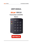
Proximity Reader
Rev.2.0.1
SINGLE DOOR CONTROLLER
Table of Contents
1. Important Safety Instructions..........................................................................3
2. General ..............................................................................................................3
3. Features.............................................................................................................4
4. Specification .....................................................................................................4
5. Identifying Supplied Parts ...............................................................................4
6. Installation.........................................................................................................5
7. Wire Color Table of the Reader .......................................................................6
8. Wire Connection to Controller.........................................................................6
9. Operation...........................................................................................................7
10. FCC Registration Information........................................................................8
11. Warranty and Service .....................................................................................9
12. RMA Request Form.......................................................................................10
2
SINGLE DOOR CONTROLLER
1. Important Safety Instructions
When using your Single Door Controller, basic safety precautions should always be followed to reduce
the risk of fire, electrical shock, and injury to persons. In addition, the following should also be
followed:
1. Read and understand all instructions.
2. Follow all warnings and instructions marked on the product.
3. Do not use liquid cleaners or aerosol cleaners. Use a damp cloth for cleaning. If necessary, use
mild soap.
4. Do not use this product near water, such as bath-tub, wash bowl, kitchen sink, laundry tub, in a wet
basement, or swimming pool.
5. This product should be operated only from the type of power source indicated on the marking label.
If you are not sure of the type of power supplied to your installation site, consult your dealer or local
power company.
6. Never push objects of any kind into this product or through the cabinet slots as they may touch
voltage points or short out parts that could result in fire or electric shock. Never spill liquid of any
kind on the product.
7. To reduce the risk of electric shock, do not disassemble this product by yourself, but take it to
qualified service whenever service or repair is required. Opening or removing the covers may
expose you to dangerous voltages or other risks. Also, incorrect reassembly can cause electric
shock when the unit is subsequently used.
8. Unplug this product from the Direct Current (DC) power source and refer to qualified service
personnel under these conditions:
a. When the power supply cord or plug is damaged or frayed.
b. If liquid has been spilled on the product.
c. If the product does not operate normally after following the operating instructions in this
manual.
Adjust only those controls that are covered by the operating instructions in this manual.
Improper adjustment of other controls that are not covered by this manual may damage the unit
and will often require extensive work by a qualified technician to restore normal operation.
d. If the product exhibits a distinct change in performance.
2. General
The STAR RF30 is an elegant looking and attractive 12"(30cm) read range proximity reader which can
be mounted on any flat wall surface. The STAR RF30 uses the electronics module in epoxy potting
that ensures successful operations even in harsh environments.
The two-color LED of green and red and the inside Piezo buzzer sound will guarantee you accurate
and reliable system operations.
3
SINGLE DOOR CONTROLLER
3. Features
- Up to 12” (30cm) Read Range
- User format available
- 26Bit Wiegand Output, RS232(Optional), ABA Track II Magnetic Stripe(Optional)
- PSK modulation
- Solid Epoxy potted
- 100% Weatherproof
- Supervisory signal(Optional)
4. Specification
Read Range
IDK50
IMC125
IDC170
IDC80
IDA150
IDA200
Reading Time
Power/Current
Output Format
External Beeper Control Input
External LED Control Input
LED/Beeper
Operating Temperature
Operating Humidity
Color
Dimensions (WxHxD)
Weight
6”(15cm)
6”(15cm)
12”(30cm)
12”(30cm)
Up to 3.3feet (1m)
Up to 4feet (1.2m)
30ms
DC 7V ~ 17V / Max. 350mA
26 bit Wiegand, Magstripe ABA Track II
Low Active, DC 0 ~ 12V, Max. 50mA
Low Active, DC 0 ~ 12V, Max. 50mA
2-Color LED(Red and Green) / Piezo Buzzer
-31℉ ~ 149℉(-35℃ ~ +65℃)
10~90% relative humidity non-condensing
Dark Gray
5.2"x 6.2"x0.8"(130x154x20.5mm)
370g (0.81lbs)
5. Identifying Supplied Parts
Please unpack and check the contents of the box.
Reader Module
RF30 Bezel
4
User’s Manual
SINGLE DOOR CONTROLLER
6. Installation
6-1. Wall Mount
Drill two 6-32 or M3 holes 3.3"(8.38cm) apart in vertical and drill one 1/2" hole for
the reader cable 1.7"(4.31cm) apart from the top hole.
(If you have installed an electric gang box then skip this step and go to step 4.2.)
6-2. Put reader cable into the center hole and install the reader module by using two
6-32 or M3 screws (Not included).
6-3. Put bezel on to the reader module then push bezel until you hear the locking sound.
5
SINGLE DOOR CONTROLLER
7. Wire Color Table of the Reader
POWER
Power(DC +7V~+17V)
DC(+)
Power(DC Ground) DC(-)
(GND)
INPUT
Beeper control input
BEEP
LED control input
LED
OUTPUT(Wiegand Format)
Wiegand Data-0
Data-0
Wiegand Data-1
Data-1
OUTPUT(ABA Track II Format)
ABA(Card Present)
CP
ABA(Clock)
CLK
ABA(Data)
Data
Note: All ABA Track II outputs are open collector output.
OUTPUT(RS232 Format)
RS232(TX)
TX
8. Wire Connection to Controller
6
Red wire
Black wire
Blue wire
Yellow wire
Green wire
White wire
Orange wire
White wire
Green wire
Violet wire
SINGLE DOOR CONTROLLER
9. Operation
9-1.
Once power is applied, you should hear three beeping sounds and LED changes color to
red-green-red indicating that the reader is in standby mode after a successful initialization and
diagnostics.
9-2.
Present proximity card to the reader until you hear the beeping sound and see the LED
changes color to Green. The reader will send the RF card data to the controller then the LED
will change color to Red again for the next reading.
9-3.
LED Control:
To change the LED colors, you may connect the LED Control Input (Yellow wire) to
ground and the Green LED will turn on indicating that the reader is in standby mode.
Present proximity card and the LED will change color to Red then Green again for the next
reading.
9-4.
Beeper Control:
In normal operation, the reader generates one beep when it reads a proximity card, however
additional beeps can be generated to improve indication for access status (granted or denied)
by forcing the beeper control input (Blue wire) to system ground level. The beeper will remain
on as long as the Blue wire is connected to system ground.
7
SINGLE DOOR CONTROLLER
10. FCC Registration Information
FCC REQUIREMENTS PART 15
Caution: Any changes or modifications in construction of this device which are not expressly approved
by the responsible for compliance could void the user's authority to operate the equipment.
NOTE: This device complies with Part 15 of the FCC Rules.
Operation is subject to the following two conditions;
1. This device may not cause harmful interface, and
2. This device must accept any interference received, including interference that may cause undesired
operation.
This equipment has been tested and found to comply with the limits for a Class B Digital Device,
pursuant to Part 15 of the FCC Rules. These limits are designed to this equipment generates, uses,
and can radiate radio frequency energy and, if not installed and used in accordance with the
instructions, may cause harmful interference to radio communications.
However, there is no guarantee that interference will not occur in a particular installation. If this
equipment does cause harmful interference to radio or television reception, which can be determined
by turning the radio or television off and on, the user is encouraged to try to correct interference by
one or more of the following measures.
1. Reorient or relocate the receiving antenna.
2. Increase the separation between the equipment and receiver.
3. Connect the equipment into an outlet on another circuit.
4. Consult the dealer or an experienced radio/TV technician for help.
8
SINGLE DOOR CONTROLLER
11. Warranty and Service
The following warranty and service information applies only to the United States of America and
Republic of Korea. For the information in other countries, please contact your local distributor.
To obtain in or out of warranty service, please prepay shipment and return the unit to the appropriate
facility listed below.
IN THE UNITED STATES
RF LOGICS Inc. Service Center
370 Amapola Ave, #106
Torrance, CA 90501
Phone: (310) 782-8383
Fax:
(310) 782-8298
E-mail: [email protected]
Web-site: www.rflogics.com
OUTSIDE OF THE UNITED STATES
ID TECK CO., LTD. Service Center
5F Ace Techno Tower Bldg.,
684-1 Deungchon-dong, Gangseo-gu,
SEOUL 157-030, KOREA
Tel.:
+82 (2) 659-0055
Fax.: +82 (2) 659-0086
E-mail: [email protected]
Web-site: www.idteck.com
Please use the original container, or pack the unit(s) in a sturdy carton with sufficient packing to
prevent damage, include the following information:
1. A proof-of-purchase indicating model number and date of purchase.
2. Bill-to address
3. Ship-to address
4. Number and description of units shipped.
5. Name and telephone number of person to contact.
6. Reason for return and description of the problem.
NOTE: Damage occurring during shipment is deemed the responsibility of the carrier, and claims
should be made directly to the carrier.
9
SINGLE DOOR CONTROLLER
12. RMA Request Form
• RMA REQUEST FORM : ORIGINAL
IDTECK Co., Ltd.
5F, Ace Techno Tower B/D, 684-1, Deungchon-Dong, Gangseo-Gu, Seoul, 157-030, Korea
TEL : +82-2-2659-0055, FAX ; +82-2-2659-0086, www.idteck.com
RMA REQUEST FORM
Send to:
RMA Customer Service
5F, Ace Techno Tower B/D 684-1,
Deungchon-Dong, Gangseo-Gu
Seoul, 157-030, Korea
Sales Person In Charge
Shipping Port :
Air / Vessel :
NO
Model
Serial Number
1
2
3
4
5
Engineer
Comment
Engineer
Comment
Engineer
Comment
RMA No. & Date :
Original Invoice No. & Date :
Requested from :
Departure Date :
Error Check Box by shipper
RS 232 Com. □
Power □
Card Reading □
Input/Output □
Keypad □
RS 422 Com □
Others □ :
RS 232 Com. □
Input/Output □
Card Reading □
RS 422 Com □
Power □
Keypad □
Card Reading □
RS 422 Com □
Power □
Keypad □
Card Reading □
RS 422 Com □
Power □
Keypad □
Card Reading □
RS 422 Com □
Others □ :
RS 232 Com. □
Input/Output □
Others □ :
RS 232 Com. □
Input/Output □
Engineer
Comment
Others □ :
Engineer
Comment
RS 232 Com. □
Input/Output □
Others □ :
Manufacture’s Verification
Product Defective :
User’s Misuse :
Communication Error :
Packing Details
Dimension(L:W:H) :
Net & Gross Weight :
Power □
Keypad □
Installation Error :
Connection Error :
Others :
No. of Units:
No. of Boxes:
Requested by:
Received by:
Signature of Buyer
Signature of IDTECK
10
SINGLE DOOR CONTROLLER
• RMA REQUEST FORM : SAMPLE
IDTECK Co., Ltd.
5F, Ace Techno Tower B/D, 684-1, Deungchon-Dong, Gangseo-Gu, Seoul, 157-030, Korea
TEL : +82-2-2659-0055, FAX ; +82-2-2659-0086, www.idteck.com
RMA REQUEST FORM
Send to:
RMA Customer Service
5F, Ace Techno Tower B/D 684-1,
Deungchon-Dong, Gangseo-Gu
Seoul, 157-030, Korea
Sales Person in Charge:
Karina Kwak
Shipping Port :
Air / Vessel :
NO
Model
SR 10
1
Engineer
Comment
others
2
3
4
5
Narita
Air
Serial Number
XXXXXXXXXXXXX
Write problem (must be
detailed).
Engineer
Comment
Engineer
Comment
Engineer
Comment
Engineer
Comment
Manufacturer’s Verification
Product Defective :
User’s Misuse :
Communication Error :
Packing Details
Dimension(L:W:H) :
30 * 25 * 80
Net & Gross Weight :
150g
Requested by:
XXXX YYYY
Signature of Buyer
RMA No. & Date :. We will send this No. , if needed.
Original Invoice No. & Date : 00-00-0-000 / 2005.10.01
Requested from :
Mr. XXXX YYYY
ABC Company
Address:
Country:
Departure Date :
2005, 10. 15
Error Check Box by Shipper
RS 232 Com. □
Power ▣
Card Reading ▣
Input/Output □
Keypad □
RS 422 Com □
Others □ :
RS 232 Com. □
Power □
Card Reading □
Input/Output □
Keypad □
RS 422 Com □
Others □ :
RS 232 Com. □
Input/Output □
Power □
Keypad □
Card Reading □
RS 422 Com □
Power □
Keypad □
Card Reading □
RS 422 Com □
Power □
Keypad □
Card Reading □
RS 422 Com □
Others □ :
RS 232 Com. □
Input/Output □
Others □ :
RS 232 Com. □
Input/Output □
Others □ :
Installation Error :
Connection Error :
Others :
No. of Units:
No. of Boxes:
20
2
Received by:
Signature of IDTECK
11
SINGLE DOOR CONTROLLER
The specification contained in this manual are subject to change without notice at any time.
5F, Ace Techno Tower B/D, 684-1, Deungchon-Dong,
Gangseo-Gu, Seoul, 157-030, Korea
Tel : (82) 2 2659-0055
Fax : (82) 2 2659-0086
E-mail : [email protected]
OCT. 2005 Copyright ©2005 IDTECK Co., Ltd.