
1
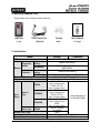
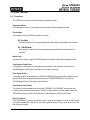
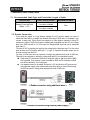
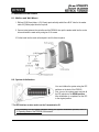
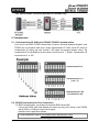
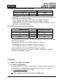
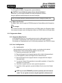
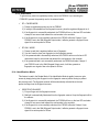
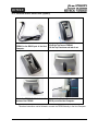
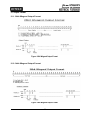
User’s Manual Fingerprint Identification Proximity Reader Table of Contents 1. Important Safety Instructions ............................................................................................................... 4 2. General ................................................................................................................................................ 4 3. Features ............................................................................................................................................... 5 4. Identifying Supplied Parts .................................................................................................................... 6 5. Specification......................................................................................................................................... 6 6. Product Overview ................................................................................................................................. 8 6.1. Functions ................................................................................................................................... 8 6.2. Product Explanation ................................................................................................................... 9 6.2.1. Panel Description ............................................................................................................ 9 6.2.2. Color Coded & Wiring Table............................................................................................. 9 7. Installation Tips & Check Points ......................................................................................................... 10 7.1. Recommended Cable Type and Permissible Length of Cable ................................................. 10 7.2. Reader Connection .................................................................................................................. 10 8. Installation of the Product.................................................................................................................... 11 8.1. Mullion and Wall Mount ............................................................................................................. 11 8.2. System Initialization .................................................................................................................. 11 8.3. Network Connection of FGR006 .............................................................................................. 12 8.4. Wiring....................................................................................................................................... 12 8.4.1. Power ............................................................................................................................ 12 8.4.2. Input Connection ........................................................................................................... 12 8.4.3. Output Connections ....................................................................................................... 12 8.4.4. External Reader Connection (Applicable to FGR006EX Only) ...................................... 13 9. Communication .................................................................................................................................. 13 9.1. Communication ID Setting for RS485 / RS422 Communication............................................... 13 9.2. RS232 Communication Port Connection ................................................................................. 13 9.3. RS485 Communication Port Connection ................................................................................. 14 9.4. RS422 Communication Port Connection ................................................................................. 14 10. Operation ......................................................................................................................................... 14 10.1. Master Card Registration Mode ............................................................................................. 14 10.1.1. Master Card Registration ............................................................................................. 14 10.1.2. Master Card Change ................................................................................................... 15 10.1.3. Master Card Function. ................................................................................................. 15 10.2. Registration Mode .................................................................................................................. 15 10.2.1. Registration Mode Function ......................................................................................... 15 10.2.2. User Card Registration. ............................................................................................... 15 10.2.3. User Card Deletion ...................................................................................................... 16 10.3. Reader Mode ......................................................................................................................... 16 10.3.1. Reader Mode Function. ............................................................................................... 16 10.3.2. Authorization ................................................................................................................ 17 10.4. Identification Mode ................................................................................................................. 17 10.5. External RS232 Serial Jack (Option) ..................................................................................... 18 11. Operating Status of FGR006 ............................................................................................................ 19 11.1. LED Indicators Status ............................................................................................................ 19 2 11.2. Beeper Sound Status ............................................................................................................. 19 12. Output Format .................................................................................................................................. 20 12.1. 26bit Wiegand Output Format ................................................................................................ 20 12.2. 34bit Wiegand Output Format ................................................................................................ 20 12.3. Normal Output Mode (Default) ............................................................................................... 21 12.4. Extended Output Mode (Selectable using the software) ........................................................ 21 13. FCC Registration Information ........................................................................................................... 22 14. Warranty Policy and Limitation of Liability ........................................................................................ 23 15. How to Make RMA Request (After Sales Service) ........................................................................... 24 3 1. Important Safety Instructions When using your Fingerprint Identification Proximity Reader, basic safety precautions should always be followed to reduce the risk of fire, electrical shock, and injury to persons. In addition, the following should also be followed: 1. Read and understand all instructions. 2. Follow all warnings and instructions marked on the product. 3. Do not use liquid cleaners or aerosol cleaners. Use a damp cloth for cleaning. If necessary, use mild soap. 4. Do not use this product near water, such as bath-tub, wash bowl, kitchen sink, laundry tub, in a wet basement, or swimming pool. 5. This product should be operated only from the type of power source indicated on the marking label. If you are not sure of the type of power supplied to your installation site, consult your dealer or local power company. 6. Never push objects of any kind into this product or through the cabinet slots as they may touch voltage points or short out parts that could result in fire or electric shock. Never spill liquid of any kind on the product. 7. To reduce the risk of electric shock, do not disassemble this product by yourself, but take it to qualified service whenever service or repair is required. Opening or removing the covers may expose you to dangerous voltages or other risks. Also, incorrect reassembly can cause electric shock when the unit is subsequently used. 8. Unplug this product from the Direct Current (DC) power source and refer to qualified service personnel under these conditions: a. When the power supply cord or plug is damaged or frayed. b. If liquid has been spilled on the product. c. If the product does not operate normally after following the operating instructions in this manual. Adjust only those controls that are covered by the operating instructions in this manual. Improper adjustment of other controls that are not covered by this manual may damage the unit and will often require extensive work by a qualified technician to restore normal operation. d. If the product exhibits a distinct change in performance. 2. General The Star FGR006/EX / iPASS IP-FGR006 / IDTECK FGR006SR is a Biometrics and Proximity Reader which can be compatible with existing proximity readers. The Star FGR006/EX / iPASS IP-FGR006 / IDTECK FGR006SR can be connected to any existing access control panel and allows access to authorized persons using their fingerprints while denying access of unauthorized persons. The Star FGR006 / iPASS IP-FGR006 / IDTECK FGR006SR has a built-in proximity reader (instead of a built-in proximity reader, the Star FGR006 / iPASS IP-FGR006 / IDTECK FGR006SR has an external reader port and fingerprint module so that the access is only allowed when the personal ID and fingerprint are authorized. Its modern design gives you an easy 4 installation (just replace existing reader) to a metal door frame (mullion) or to any flat wall surface. The Star FGR006/EX / iPASS IP-FGR006 / IDTECK FGR006SR ensures you a successful operation where you want biometrics access control. The Star FGR006/EX / iPASS IP-FGR006 / IDTECK FGR006SR has three LED of red, green and lens (upper right) as well as an inside beeper to guarantee you an accurate and reliable access control. 3. Features - 1:1 Verification and 1:N Identification - Identification Method: by Auto Touch Sensor - 125 KHz Proximity and Fingerprint Recognition - 1,000 / 2,000 / 4,000 Fingerprint Users - Various Operating Modes - ID only Function for Persons with Unregisterable Fingerprints - Network Communication via RS232 / RS422 / RS485 (Max.255ch) - Upload / Download Fingerprint Templates using PDA or Notebook (Optional, RS232C Stereo Jack required) - Fingerprint Register / Reader Mode using Master Card - Off-line Add / Delete Function using Master Card - 26bit Wiegand (default) and ABA Track II (optional) Output Format - 1ea of External Reader Port (FGR006EX): 26 / 34bit Wiegand, 4 / 8bit Burst for PIN and ABA Track II - High Protection from Scratch and ESD (Electro Static Discharge) - High Quality Optical Sensor - Tamper Switch - Options: Supervisory Signal, RS232C Stereo Jack - Compatible Software: STARWATCH DUAL PRO I / II, STARWATCH iTDC PRO I / II FINGERPRINT ENROLLMENT PRO 2006 - Compatible Controller: iCON100, iTDC, Third Party Controller, Standalone Controller * Comparison Table FGR006 FGR006EX IP-FGR006 FGR006SR Built-in 125KHz (4”) Proximity Reader RF Only / Fingerprint Only* / RF+ Fingerprint 1ea of External Reader Port ASK[EM] Format, Built-in 125KHz (4”) Proximity Reader RF Only / Fingerprint Only* / RF+ Fingerprint Built-in 13.56MHz (4”) Contactless Smart Card Reader Smart Card Only / Fingerprint Only* / Smart + Fingerprint * NOTE For the product produced in 2010 and later, Auto Touch Sensor is basically provided. But for the product produced before 2010, Auto Touch Sensor should be optionally purchased 5 4. Identifying Supplied Parts Please unpack and check the contents of the box. Main Unit RS232 Serial Port (1 ea) (Optional) Screws User’s Manual (4ea) (1 Copy) 5. Specification CPU Memory Model Fingerprint Module Controller FGR006 FGR006 Read Range IP-FGR006 FGR006SR Active Type 1MByte Flash Memory 1MByte/ 4MByte Flash Memory 8MB SDRAM Data Memory Fingerprint User Fingerprint Template Size Passive Type 32bit ARM9 and Dual 8bit Microprocessor Program Memory Program Memory Data Memory FGR006 Reading Time (Card) Verification / Identification Time Power / Current FGR006EX 128KByte Flash Memory 256KByte Serial Flash Memory, 4KByte SRAM 1,000 / 2,000 / 4,000 Fingerprint Users 800 Bytes for 2 Fingerprint Templates IDK50 / IMC125: Up to 2 inches (5cm) IDC80 / IDC170: Up to 4 inches (10cm) IPK50: Up to 2 inches (5cm) IPC80 / IPC170: Varies depending on Up to 4 inches (10cm) the External Reader ISK50 / IHC80 / IMC135: Up to 2 inches (5cm) ISC80: Up to 4 inches (10cm) IDA150 / IDA200 Compatible 30ms Less than 1sec. / Less than 2sec. DC 12V / Max. 250mA 6 FGR006 / IP-FGR006 External Reader Port FGR006SR Communication Baud Rate Input Port Output Port LED Indicator / Beeper Operating Temperature Operating Humidity Color / Material Weight / Dimension (W x H x T) Certification Fingerprint Module RF Reader 1 port (26bit Wiegand, 4/8bit Burst for PIN, ABA Track II) N/A 1 port (34bit Wiegand, 4/8bit Burst for PIN, ABA Track II) RS232 / RS422 / RS485 (Max.255ch) TCP/IP (External LAN Converter Required) 9,600bps (Recommended) / 4,800bps, 19,200bps and 38,400bps (Selectable) 2 ports (External LED Control, External Buzzer Control) 2 ports (Error-Output , OK-Output (Open Collector Output)) 3 Array LED Indicators (Red and Green) / Piezo Buzzer -20° to +60°C (-4° to +140°F) -35° to + 65°C (-31° to +149°F) 10% to 90% relative humidity non-condensing Pearl Dark Gray and Light Gray / Polycarbonate 259.5g (0.57lbs) / 66mm x 129mm x 52mm (2.6” x 5.1” x 2.0”) FCC, CE, MIC * Finger Module Specification Resolution Capture Image Size Extraction Image Size Sensing Area Scanner FAR(False Acceptance Ratio) FRR(False Reject Ratio) ESD(Electro Static Discharge) Verification Time Identification 500dpi 356 X 292 pixels 248 X 292 pixels 12.7 X 14.9mm High Quality Option Sensor 0.001% 0.1% 15KV Less than 1sec. Less than 2sec. 7 6. Product Overview 6.1. Functions The FGR006 is a proximity reader with a built-in fingerprint module. Registration Mode In the registration mode, you can register new user cards or delete existing user cards. Reader Mode In the reader mode, the FGR006 operates as a reader. RF Only Mode : If a card is authorized, the corresponding card number will be transmitted to the controller. RF + FINGER Mode : If a fingerprint is authorized, the corresponding card number will be transmitted to the controller. Master Card A master card is used to toggle the FGR006 between the reader mode and the registration mode. Card Number Output Form If a fingerprint is authorized, the corresponding card number is transmitted to the controller via 26/34bit Wiegand or ABA Track II according to the output type setting. Error Signal Output If a fingerprint fails to be authorized, the FGR006 (FGR006EX) will generate 500ms fingerprint error signals of low active pulse.(Applicable only when your FGR006(FGR006EX) is set to use the 26/34bit Wiegand output) This signal is open collector. Card Number Input Format This function is only available when you use the FGR006EX. The FGR006EX receives the card number from the external reader while the FGR006 contains a built-in proximity reader inside. The FGR006EX receives the card input in 8bit Burst or 26bit Wiegand or ABA Track II format. Dual Finger Mode Dual Finger Mode is a function that allows a user to register two fingers for one ID so that the user can receive authentication with either of the two registered fingers. This is useful when one of the user’s fingers is injured. 8 6.2. Product Explanation 6.2.1. Panel Description Tamper Switch Status LED Cable Fingerprint Scanner Label DIP Switch 6.2.2. Color Coded & Wiring Table FGR006 IP-FGR006 FGR006SR SIGNAL Main Power (+12V) Power Ground (GND) Wiegand Data 0 Out / ABA Track II Data Out Wiegand Data 1 Out / ABA Track II Clock Out Error Signal Out / ABA Track II CP Out OK Signal Out Tamper Switch Out Wiegand Data 0 In (EX) Wiegand Data 1 In (EX) LED Control In Buzzer Control In RS422 (TX+) RS422 (TX-) RS422 (RX+) RS422 (RX-) COLOR FGR006EX Red Black Green White Orange Orange with Black stripe Purple NC Pink NC Cyan Blue with White stripe White with Red stripe Gray Yellow Brown Blue * Please cut out the tail connector before installation. For RS485 communication, you should put Gray (TX+) wire and Brown (RX+) wire together as well as Yellow (TX-) wire and Blue (RX-) wire. We recommend you use the INC300 converter. 9 7. Installation Tips & Check Points 7.1. Recommended Cable Type and Permissible Length of Cable DESCRIPTION CABLE SPECIFICATION MAXIMUM DISTANCE Belden #9512, 22 AWG 4 conductor, shielded Reader (Power and Data) 150m Reader -> ACU Belden #9514, 22 AWG 8 conductor, shielded * Thicker wires are required if you connect the reader with high current consumption. 7.2. Reader Connection If you install the reader in a long distance between the ACU and the reader, you have to remind that there will be a voltage drop between both ends of GND wire. For example, if you connect a reader with 100mA current consumption at 100m distance (assume to using DC resistance of cable of 100Ω/100m) and the reader power is supplied from the ACU, the voltage drop of the GND wire will be 1V. In this case, the Wiegand data signal can not be measured lower than 1V. The most of ACU is capturing the signal by the voltage level of data input and 1V is the critical point whether the ACU read the data logic “1” or logic “0” therefore the reader output can not be read correctly from the ACU. You have to think about how you reduce the voltage drop between both ends of GND wire. There will be two methods to reduce the voltage drop and ACU can read data correctly. Reduce the DC resistance of GND wire; Using thick cable or add more wires to GND wire in parallel. If you connect 4 wires in parallel for GND, the DC resistance of GND wire will be reduced to 1/4 of single wire. Use separate power for the reader; Disconnect +12V wire from the ACU and connect external power supply to the reader nearby then there will be no current flow through the GND wire and no voltage drop between both ends of GND wire. < Reader connection using additional wires > < Reader connection using external power supply > 10 8. Installation of the Product 8.1. Mullion and Wall Mount 1. Drill two Ø1/8"(3mm) holes, 4.4"(113mm) apart vertically and drill one Ø1/2" hole for the reader cable 2.2"(56mm) apart from the top hole. 2. Connect wires between the controller and the FGR006, then put the reader cable into the center hole and install the main unit by using two 3-16 screws. 3 Put the bezel into the main unit and push it until it clicks into place. 8.2. System Initialization You can initialize the system using the DIP switches on the back of the FGR006. First, turn on the system power and set all the DIP switches to the DOWN position. After initialization is completed, set the DIP to the original position. * The DIP Switches are also used to set the Communication ID. For information on the system indication during the system initialization process, refer to 11.Operating Status of the FGR006 of this manual. 11 8.3. Network Connection of FGR006 8.4. Wiring 8.4.1. Power - Connect +12V(+) wire of Power to Red wire of FGR006 - Connect GND(-) wire of Power to Black wire of FGR006 8.4.2. Input Connection - The Green LED turns on if the LED Control Input wire is connected to the GND. - A beep is generated if the Beeper Control Input wire is connected to the GND. 8.4.3. Output Connections [ 26bit Wiegand Output] [ABA Track II Output] 12 8.4.4. External Reader Connection (Applicable to FGR006EX Only) 9. Communication 9.1. Communication ID Setting for RS485 / RS422 Communication If you want to use RS485 / RS422 communication to upload / download fingerprint templates, each FGR006 unit on the network must have a unique Communication ID. There is 8-bit DIP switch for communication ID setting and each channel of DIP switch has assigned address values. The communication ID is calculated by the sum values of each bit set to “1” position. Communication ID can be set from ‘0’ to ‘254’. Communication ID = 0 Communication ID = 17 (1+16 = 17) Communication ID = 205 (1+4+8+64+128 = 205) 9.2. RS232 Communication Port Connection For RS232 communication, you should use an external RS232 serial cable. - Connect the RS232 serial cable between the stereo jack plug on the bottom of the FGR006 and the COM1 or COM2 port of the Host Computer - Install and run the application software. For more information, refer to 10.5 External RS232 Serial Jack (OPTION). 13 9.3. RS485 Communication Port Connection FGR006(FGR006EX) Gray wire and Brown wire RS485-A Yellow wire and Blue wire RS485-B RS485/RS232 Converter RS485+ RS485- An RS-485/RS-232 converter is required to connect serial communication RS485 between the FGR006 Main Unit and the Host Computer. - Connect RS485 A, Gray and Brown wires of Main Unit to RS485+ of Converter. - Connect RS485 B, Yellow and Blue wires of Main Unit to RS485- of Converter. - Plug the RS232 9-pin connector of INC300 converter into COM1 or COM2 Port of Computer. - Install and run the application software. 9.4. RS422 Communication Port Connection FGR006(FGR006EX) RS422/RS232 Converter Yellow Gray Blue RS422-Tx[-] RS422-Tx[+] RS422-Rx[-] RxRx+ Tx- Brown RS422-Rx[+] Tx+ An RS422/RS232 converter is required for RS422 communication between the FGR006 Main Unit and the Host Computer. - Connect RS422 Tx[-],Yellow wire of FGR006 to Rx[-] port of Converter. - Connect RS422 Tx[+], Gray wire of FGR006 to Rx[+] port of Converter. - Connect RS422 Rx[-], Blue wire of FGR006 to Tx[-] port of Converter. - Connect RS422 Rx[+], Brown wire of FGR006 to Tx[+] port of Converter. - Plug the RS232 9-pin connector of Converter into COM1 or COM2 Port of Host Computer. - Install and run the application software. 10. Operation 10.1. Master Card Registration Mode 10.1.1. Master Card Registration The card presented to the FGR006 for the first time after initialization becomes the master card. For information on the system indication during the master card registration process, refer to the 11.Operating Status of FGR006 of this manual. ※ NOTE: Fingerprint verification is not used for the Master Card. 14 10.1.2. Master Card Change You can register the Master Card again after system initialization. ※ CAUTION : If you initialize the system, all user data will be deleted. Alternatively, you can change the Master Card using the application software. Using the application software keeps the user data unchanged. Refer the software manual for detailed instructions on how to change the master card. 10.1.3. Master Card Function. The Master Card is used to toggle the FGR006 between the Reader Mode and the Registration Mode. ※ For example, If you present the master card in the Reader Mode, the FGR006 shifts to the Registration Mode. If you present the master card in the Registration Mode, the FGR006 shifts to the Reader Mode. 10.2. Registration Mode 10.2.1. Registration Mode Function In the Registration Mode, you can register new user cards or delete registered user cards. If you present a registered user card, it will be removed from the FGR006. (4 beeps) If you present an unregistered user card, it will be newly registered to the FGR006. (3 beeps) 10.2.2. User Card Registration. RF + FINGER MODE: After presenting the user card you’d like to register, you should enter the desired fingerprint twice. Follow the steps below to register a new user card; 1) Present the proximity card to the FGR006. 2) Place the fingerprint on the fingerprint scanner while red light is illuminated from it 3) Lift the fingerprint up when the red light from the scanner turns off. 4) Place the fingerprint on the fingerprint scanner once again while the red light is illuminated again. 5) You can hear 3 beeps if the registration is successfully completed, or 2 beeps if the registration is not successful. 6) If you’d like to register more user cards, repeat the steps above. 7) If you’d like to finish registration, present the Master Card to return to the Reader Mode. ※ NOTE: If you use the FGR006EX, present the proximity card to the external reader. You can register new users using the application software as well. 15 RF Only: If you’d like to register a new user without use of fingerprint, don’t place the fingerprint on the fingerprint scanner and wait until the red light from the scanner turns off automatically. 1) Just present the user card you’d like to register. 2) After the registration is successfully completed, you’ll hear 3 beeps. If the registration is not successful, you’ll hear only 2 beeps. 3) If you’d like to register more user cards, repeat the procedure above. Or, if you’d like to finish registration, present the Master Card to return to the Reader Mode. Figure: Correct placement of fingerprint 10.2.3. User Card Deletion To delete registered user cards, proceed as follows; 1) Present to the FGR006 the Proximity Card you’d like to delete. 2) After the deletion is successfully completed, you’ll hear 4 beeps. If the deletion is not successful, you’ll hear 2 beeps. 3) If you’d like to delete more user cards, repeat the steps above. 4) To finish user deletion, present the Master Card to return to the Reader Mode. ※ NOTE: If you use the FGR006EX, you should present the proximity card to the external reader. You can delete existing users using the application software as well. 10.3. Reader Mode 10.3.1. Reader Mode Function. In the Reader Mode, the FGR006 authorizes or denies users who attempt access by presenting their cards. - If a user is authorized, the FGR006 transmits the card number to the controller. - If a user fails to be authorized, the FGR006 transmits the error signal to the controller. For information on the system indication in the Reader Mode, refer to 11.Operating Status of the FGR006 of this manual. 16 10.3.2. Authorization To gain access, present a registered proximity card to the FGR006. If you are using the FGR006EX, present the proximity card to the external reader. RF + FINGER MODE: 1) Present a registered proximity card to the FGR006. 2) If red light is illuminated from the fingerprint scanner, place the registered fingerprint on it. 3) If the fingerprint is successfully authorized, the FGR006 will turn on the lens LED and make a beep for one second and transmit the card number to the controller. 4) If the fingerprint is not successfully authorized, the FGR006 will make 2 beeps. If your FGR006 is set in the 26bit Wiegand Output mode, it will also generate a fingerprint error signal of low active pulse for 500ms. RF-ONLY MODE: 1) Present a card that is registered without use of fingerprint. 2) You don’t need to place your fingerprint on the fingerprint scanner. 3) If the presented card is successfully authorized, the FGR006 will turn on the lens LED and make a beep for one second and transmit the card number to the controller. 4) If the presented card is not successfully authorized, the FGR006 will make 2 beeps. If your FGR006 is set in the 26bit Wiegand Output mode, it will also generate a fingerprint error signal of low active pulse for 500ms. 10.4. Identification Mode This feature is used in the Reader Mode. If the Identification Mode is applied, users can gain access by simply placing their fingerprint on the fingerprint scanner (without having to present the proximity card). The fingerprint scanner will be automatically activated when the user places the finger onto the fingerprint scanner. IDENTIFICATION MODE: 1) Put your finger onto the fingerprint scanner. 2) Red light is automatically illuminated from the fingerprint scanner. Keep the fingerprint still on the scanner. 3) If the fingerprint is successfully authorized, the FGR006 will turn on the lens LED and make a beep for one second and transmit the card number to the controller. 4) If the fingerprint is not successfully authorized, the FGR006 will make 2 beeps. If your FGR006 is set in the 26bit Wiegand Output mode, it will also generate a fingerprint error signal of low active pulse for 500ms. 17 10.5. External RS232 Serial Jack (Option) This cable is used to connect the FGR006 to the RS232 port of the Host Lift off the Top Case of FGR006. Pull the Top Case down and take it out. Computer. Insert the RS232 Serial Jack to the Connect the D-sub Connector to the bottom of the FGR006 RS232 port of the Host Computer. This above instructions can be followed to connect the FGR006 directly to the Host Computer. 18 11. Operating Status of FGR006 LED OFF Applicable to FGR006: V 3.00 or above FGR006EX: V 3.00 or above. 11.1. LED Indicators Status LED LED ON LED BLINKING STATUS FUNCTION The system is booting after power is supplied After the system initialization is completed, the first card presented to the FGR006 becomes the Master Card. Booting Register Master Card Registration Mode You can register or delete user cards. Reader Mode Users can access the door in this mode. Initialization If system initialization is performed, all registered users are deleted. Initialization Completion System initialization is completed. 11.2. Beeper Sound Status BEEP NUMBER OF BEEPS STATUS 1 beep (1 sec.) Access Granted 2 beeps Error (Fingerprint or operation error) 3 beeps User Card Registered 4 beeps User Card Deleted 19 12. Output Format 12.1. 26bit Wiegand Output Format Figure: 26bit Wiegand Output Format 12.2. 34bit Wiegand Output Format Figure: 34bit Wiegand Output Format 20 12.3. Normal Output Mode (Default) Figure: Normal Output Mode Timing 12.4. Extended Output Mode (Selectable using the software) Figure: Extended Output Mode Timing 21 13. FCC Registration Information FCC REQUIREMENTS PART 15 Caution: Any changes or modifications in construction of this device, which are not expressly approved by the manufacturer for compliance, could void the user's authority to operate the equipment. Note: This device complies with Part 15 of the FCC Rules. Operation is subject to the following two conditions; 1. This device may not cause harmful interference, and 2. This device must accept any interference received, including interference that may cause undesired operation. This equipment has been tested and found to comply with the limits for a Class A Digital Device, pursuant to Part 15 of the FCC Rules. These limits are designed to this equipment generates, uses, and can radiate radio frequency energy and, if not installed and used in accordance with the instructions, may cause harmful interference to radio communications. However, there is no guarantee that interference will not occur in a particular installation. If this equipment does cause harmful interference to radio or television reception, which can be determined by turning the radio or television off and on, the user is encouraged to try to correct interference by one or more of the following measures. 1. Reorient or relocate the receiving antenna. 2. Increase the separation between the equipment and receiver. 3. Connect the equipment into an outlet on another circuit. 4. Consult the dealer or an experienced radio/TV technician for help. 22 14. Warranty Policy and Limitation of Liability IDTECK warrants this product against defects in material and workmanship for the period specified below from the date of purchase under normal customer use. This Warranty doesn’t apply: 1) to any product which has been dismantled without authorization of IDTECK or/and has a damaged or detached QC label on its back side; 2) to any losses, defects, or damages caused by improper testing, operation, installation, maintenance, modification, alteration, or adjustment; 3) to any product with a damaged or faded serial number on it; or 4) to any losses, defects, or damages caused by lightning or other electrical discharge, natural disaster, misuse, accident or neglect. This Limited Warranty is in lieu of all other warranties, obligations, or liabilities on the part of IDTECK, and IDTECK DISCLAIMS ANY AND ALL WARRANTY, WHETHER EXPRESS OR IMPLIED, OF MERCHANTABILITY OR FITNESS FOR A PARTICULAR PURPOSE.IDTECK does not, and cannot, know who is present, what property is located, where this product will be used; it would be extremely difficult to determine the actual damages that may result from a failure of the product to perform as anticipated; and the low price of this product is based upon the nature of the product provided and the limited liability that IDTECK assumes. IDTECK IS NOT RESPONSIBLE FOR ANY PERSONAL INJURY, PROPERTY DAMAGE OR LOSS, DIRECT, SPECIAL, INCIDENTAL OR CONSEQUENTIAL DAMAGES, OR OTHER LOSS, AND IDTECK’S MAXIMUM LIABILITY SHALL NOT IN ANY CASE EXCEED THE PURCHASE PRICE OF THE PRODUCT. To obtain repair or replacement under the terms of this warranty, visit IDTECK’s Website (http://www.idteck.com) and place an online RMA request. After an RMA code is issued, return the product along with the authorization RMA code. >> Warranty Period Product Category 1 RF CARDS (ACTIVE TYPE) FINGERPRINT MODULE / SENSOR 2 RF READERS (WITHOUT EPOXY POTTING) 3 STANDALONE CONTROLLERS 4 CONTROL PANELS 5 FINGERPRINT READERS 6 RF READERS (WITH EPOXY POTTING) 7 RF CARDS (PASSIVE TYPE) 23 Warranty Period 1 year 2 years Lifetime 15. How to Make RMA Request (After Sales Service) To make the RMA request, the product must be initially registered on IDTECK webpage. Please attach the RMA request form on the product and send it to IDTECK RMA Center. Please follow the instructions below: 1. Please register the RMA request via IDTECK webpage. : www.idteck.com “Support & Download” “Online RMA” “RMA REQUEST” (Please refer to the IDTECK webpage for more details.) 2. RMA Code will be issued after the RMA Center reviews the RMA request form. 3. Fill out the A/S request form (included in the product package) and attach it to the product using the aluminum string. 4. Enclose the product along with the RAM Code and send it to IDTECK RMA Center. (Product without RMA Code is not accepted.) If you have any questions or problems regarding the RMA services, please contact us using the following contact information below. Friendly representatives at IDTECK are always standing by to provide the best after sales services. IDTECK Headquarter 5F, Ace Techno Tower B/D, 684-1, Deungchon-Dong, Gangseo-Gu, Seoul, 157-030, Korea Tel: +82-2-2659-0055 (Ext. 158) Fax: +82(2) 2659-0086 E-mail: [email protected] Website: www.idteck.com E-Training Center: http://www.idtecktraining.com IDTECK Production Facility and RMA Center 3F, 10/10-1/10-2, Dodang-Dong, Weonmi-Gu, Bucheon-Si, Gyeonggi-Do 157-030, Korea Tel: +82-2-2659-0055 (Ext. 158) Fax: +82(2) 2659-0086 E-mail: [email protected] Website: www.idteck.com E-Training Center: http://www.idtecktraining.com 24 The specifications contained in this manual are subject to be changed following product update 5F, Ace Techno Tower B/D, 684-1, Deungchon-Dong, Gangseo-Gu, Seoul, 157-030, Korea Tel : +82-2-2659-0055 Fax : +82-2-2659-0086 E-mail : [email protected] Jan. 2010 Copyright © IDTECK Co., Ltd.


![ASK[EM] Format Proximity Card Reader](http://vs1.manualzilla.com/store/data/005664035_1-4bfcda642b959ea77ca1da56751cb6af-150x150.png)


![13.56MHz [MIFARE] Contactless Smart Card](http://vs1.manualzilla.com/store/data/005689074_1-1b5ba2b7f854420e24ee51932ec4423a-150x150.png)