1
Part No. 09564-3, Rev A
December 1995
Page 3 of 8
Installing a Modulus 9 -48VDC Enclosure
Assembling an
Enclosure
The Modulus 9 is shipped from the factory in one of these ways:
Positioning an
Enclosure
The Modulus 9 can be positioned as follows:
Installing an
Enclosure
Install the enclosure as follows. Refer to the Modulus 9 and 21 Installation and
Operation Guide for general enclosure information.
¥ Unassembled, with a power supply
¥ Assembled, containing product cards and backplanes, Þller panels, and a power
supply module
Determine which way your enclosure was shipped. Follow the appropriate
instructions in the installation procedure below.
¥ On a ßat surfaceÑa tabletop or bench
¥ On a shelf in a standard 19-inch electrical-equipment rack
Determine which way your enclosure will be positioned. Follow the appropriate
instructions in the installation procedure below.
Warning!
Before beginning the installation procedure, ensure that the electrical power source
is disconnected from input wires to be connected to the Modulus.
Installing a Modulus 9 -48VDC Enclosure
Step
Action
1
Position the enclosure on:
¥ A ßat surface, for standalone operation
¥ An equipment-rack shelf, for rack-mount operation
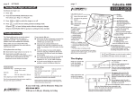
Note the key, taped inside the front door, as shown in Figure 2. You can
lock the enclosure to prevent unauthorized access.
2
If the enclosure is empty, install communications-product backplane(s)
in it, as described in the Modulus 9 and 21 Installation and Operation
Guide, Chapter 3.
3
IMPORTANT
At the rear of the enclosure, ensure that the Power switch is in the OFF
(left) position.
4
At the rear of the enclosure, remove the terminal cover by unscrewing
the captive screw and pulling up and out (Figure 1).