1
A NovAtel Precise Positioning Product:
RTKNAV/RTSTATIC
Includes Developers Kit Documentation
For Windows 95/98/2000/NT/XP
User Manual
OM-20000099 Rev 0B
Proprietary Notice
RTKNAV/RTSTATIC User Manual
Publication Number:
Revision Level:
Revision Date:
Software Version:
OM-20000099
0B
2006/02/17
Real-Time Multi-Remote GPS Processing Software
Version 3.15
Proprietary Notice
Information in this document is subject to change without notice and does not represent a
commitment on the part of NovAtel Inc. The software described in this document is
furnished under a licence agreement or non-disclosure agreement. The software may be
used or copied only in accordance with the terms of the agreement. It is against the law to
copy the software on any medium except as specifically allowed in the license or nondisclosure agreement.
No part of this manual may be reproduced or transmitted in any form or by any means,
electronic or mechanical, including photocopying and recording, for any purpose without
the express written permission of a duly authorized representative of NovAtel Inc.
The information contained within this manual is believed to be true and correct at the
time of publication.
NovAtel is a registered trademark of NovAtel Inc.
Waypoint, RTKNAV and RTSTATIC are trademarks of NovAtel Inc.
Windows 98, 2000, and XP are trademarks of the Microsoft Corporation.
All other brand names are trademarks of their respective holders.
© Copyright 2000-2006 NovAtel Inc. All rights reserved. Unpublished rights
reserved under International copyright laws. Printed in Canada on recycled paper.
Recyclable.
Software Licence
Software Licence
BY INSTALLING, COPYING, OR OTHERWISE USING THE SOFTWARE PRODUCT,
YOU AGREE TO BE BOUND BY THE TERMS OF THIS AGREEMENT. IF YOU DO NOT
AGREE WITH THESE TERMS OF USE, DO NOT INSTALL, COPY OR USE THIS
ELECTRONIC PRODUCT (SOFTWARE, FIRMWARE, SCRIPT FILES, OR OTHER
ELECTRONIC PRODUCT WHETHER EMBEDDED IN THE HARDWARE, ON A CD OR
AVAILABLE ON THE COMPANY WEB SITE) (hereinafter referred to as "Software").
(a)
(b)
(c)
(d)
(e)
1. License: NovAtel Inc. ("NovAtel") grants you a non-exclusive, non-transferable license
(not a sale) to, where the Software will be used on NovAtel supplied hardware or in
conjunction with other NovAtel supplied software, use the Software with the product(s) as
supplied by NovAtel. You agree not to use the Software for any purpose other than the
due exercise of the rights and licences hereby agreed to be granted to you.
2. Copyright: NovAtel owns, or has the right to sublicense, all copyright, trade secret,
patent and other proprietary rights in the Software and the Software is protected by
national copyright laws, international treaty provisions and all other applicable national
laws. You must treat the Software like any other copyrighted material except that you may
make one copy of the Software solely for backup or archival purposes (one copy may be
made for each piece of NovAtel hardware on which it is installed or where used in
conjunction with other NovAtel supplied software), the media of said copy shall bear labels
showing all trademark and copyright notices that appear on the original copy. You may not
copy the product manual or written materials accompanying the Software. No right is
conveyed by this Agreement for the use, directly, indirectly, by implication or otherwise by
Licensee of the name of NovAtel, or of any trade names or nomenclature used by
NovAtel, or any other words or combinations of words proprietary to NovAtel, in
connection with this Agreement, without the prior written consent of NovAtel.
3. Patent Infringement: NovAtel shall not be liable to indemnify the Licensee against any
loss sustained by it as the result of any claim made or action brought by any third party for
infringement of any letters patent, registered design or like instrument of privilege by
reason of the use or application of the Software by the Licensee or any other information
supplied or to be supplied to the Licensee pursuant to the terms of this Agreement.
NovAtel shall not be bound to take legal proceedings against any third party in respect of
any infringement of letters patent, registered design or like instrument of privilege which
may now or at any future time be owned by it. However, should NovAtel elect to take such
legal proceedings, at NovAtel's request, Licensee shall co-operate reasonably with
NovAtel in all legal actions concerning this license of the Software under this Agreement
taken against any third party by NovAtel to protect its rights in the Software. NovAtel shall
bear all reasonable costs and expenses incurred by Licensee in the course of cooperating with NovAtel in such legal action.
4. Restrictions: You may not:
copy (other than as provided for in paragraph 2), distribute, transfer, rent, lease, lend,
sell or sublicense all or any portion of the Software except in the case of sale of the
hardware to a third party;
modify or prepare derivative works of the Software;
use the Software in connection with computer-based services business or publicly
display visual output of the Software;
transmit the Software over a network, by telephone or electronically using any means
(except when downloading a purchased up[grade from the NovAtel web site); or
reverse engineer, decompile or disassemble the Software.
You agree to keep confidential and use your best efforts to prevent and protect the
contents of the Software from unauthorized disclosure or use.
5. Term and Termination: This Agreement and the rights and licences hereby
granted shall continue in force in perpetuity unless terminated by NovAtel or
Licensee in accordance herewith. In the event that the Licensee shall at any
time during the term of this Agreement: i) be in breach of its obligations
hereunder where such breach is irremediable or if capable of remedy is not
remedied within 30 days of notice from NovAtel requiring its remedy; then and in
any event NovAtel may forthwith by notice in writing terminate this Agreement
together with the rights and licences hereby granted by NovAtel.
Software Licence
Licensee may terminate this Agreement by providing written notice to NovAtel.
Upon termination, for any reasons, the Licensee shall promptly, on NovAtel's request,
return to NovAtel or at the election of NovAtel destroy all copies of any documents and
extracts comprising or containing the Software. The Licensee shall also erase any copies
of the Software residing on Licensee's computer equipment. Termination shall be without
prejudice to the accrued rights of either party, including payments due to NovAtel. This
provision shall survive termination of this Agreement howsoever arising.
6. Warranty: NovAtel does not warrant the contents of the Software or that it will be error
free. The Software is furnished "AS IS" and without warranty as to the performance or
results you may obtain by using the Software. The entire risk as to the results and
performance of the Software is assumed by you. See product enclosure, if any for any
additional warranty.
7. Indemnification: NovAtel shall be under no obligation or liability of any kind (in contract,
tort or otherwise and whether directly or indirectly or by way of indemnity contribution or
otherwise howsoever) to the Licensee and the Licensee will indemnify and hold NovAtel
harmless against all or any loss, damage, actions, costs, claims, demands and other
liabilities or any kind whatsoever (direct, consequential, special or otherwise) arising
directly or indirectly out of or by reason of the use by the Licensee of the Software whether
the same shall arise in consequence of any such infringement, deficiency, inaccuracy,
error or other defect therein and whether or not involving negligence on the part of any
person.
8. Disclaimer and Limitation of Liability:
(a) THE WARRANTIES IN THIS AGREEMENT REPLACE ALL OTHER
WARRANTIES, EXPRESS OR IMPLIED, INCLUDING ANY WARRANTIES OF
MERCHANTABILITY OR FITNESS FOR A PARTICULAR PURPOSE. NovAtel
DISCLAIMS AND EXCLUDES ALL OTHER WARRANTIES. IN NO EVENT WILL
NovAtel's LIABILITY OF ANY KIND INCLUDE ANY SPECIAL, INCIDENTAL OR
CONSEQUENTIAL DAMAGES, INCLUDING LOST PROFITS, EVEN IF NovAtel
HAS KNOWLEDGE OF THE POTENTIAL LOSS OR DAMAGE.
(b)NovAtel will not be liable for any loss or damage caused by delay in furnishing the
Software or any other performance under this Agreement.
(c)NovAtel's entire liability and your exclusive remedies for our liability of any kind
(including liability for negligence) for the Software covered by this Agreement and all
other performance or non-performance by NovAtel under or related to this Agreement
are to the remedies specified by this Agreement.
9. Governing Law: This Agreement is governed by the laws of the Province of Alberta,
Canada. Each of the parties hereto irrevocably attorns to the jurisdiction of the courts of
the Province of Alberta.
10. Customer Support: For Software UPDATES and UPGRADES, and regular customer
support, contact the NovAtel GPS Hotline at 1-800-NOVATEL (U.S. or Canada only), or
403-295-4900, Fax 403-295-4901, e-mail to [email protected], website:
http://www.novatel.com or write to:
NovAtel Inc.
Customer Service Dept.
1120 - 68 Avenue NE,
Calgary, Alberta, Canada T2E 8S5
Warranty Policy
Warranty Policy
NovAtel Inc. warrants that during the warranty period (a) its products will
be free from defects and conform to NovAtel specifications; and (b) the
software will be free from error which materially affect performance,
subject to the conditions set forth below, for the following periods of time:
Computer Discs
Software Warranty
Ninety (90) Days from date of sale
One (1) Year from date of sale
Date of sale shall mean the date of the invoice to the original customer for
the product.
Purchaser’s exclusive remedy for a claim under this warranty shall be
limited to the repair or replacement at NovAtel’s option and at NovAtel’s
facility, of defective or nonconforming materials, parts or components or
in the case of software, provision of a software revision for implementation
by the Buyer.
All material returned under warranty shall be returned to NovAtel prepaid
by the Buyer and returned to the Buyer, prepaid by NovAtel. The
foregoing warranties do not extend to (i) nonconformities, defects or errors
in the Products due to accident, abuse, misuse or negligent use of the
Products or use in other than a normal and customary manner,
environmental conditions not conforming to NovAtel’s specifications, or
failure to follow prescribed installation, operating and maintenance
procedures, (ii) defects, errors or nonconformities in the Products due to
modifications, alterations, additions or changes not made in accordance
with NovAtel’s specifications or authorized by NovAtel, (iii) normal wear
and tear, (iv) damage caused by force of nature or act of any third person,
(v) shipping damage, (vi) service or repair of Product by the Purchaser
without prior written consent from NovAtel, (vii) Products designated by
NovAtel as beta site test samples, experimental, developmental,
preproduction, sample, incomplete or out of specification Products, (viii)
returned Products if the original identification marks have been removed
or altered or (ix) Services or research activities.
THE WARRANTIES AND REMEDIES ARE EXCLUSIVE AND ALL
OTHER WARRANTIES, EXPRESS OR IMPLIED, WRITTEN OR ORAL,
INCLUDING THE IMPLIED WARRANTIES OF MERCHANTABILITY OR
FITNESS FOR ANY PARTICULAR PURPOSE ARE EXCLUDED.
NOVATEL SHALL NOT BE LIABLE FOR ANY LOSS, DAMAGE,
EXPENSE, OR INJURY ARISING DIRECTLY OR INDIRECTLY OUT OF
THE PURCHASE, INSTALLATION, OPERATION, USE OR LICENSING
OR PRODUCTS OR SERVICES. IN NO EVENT SHALL NOVATEL BE
LIABLE FOR SPECIAL, INDIRECT, INCIDENTAL OR CONSEQUENTIAL
DAMAGES OF ANY KIND OR NATURE DUE TO ANY CAUSE.
TABLE OF CONTENTS
CHAPTER 1 INTRODUCTION
1
Section 1 What is RTKNav? ..................................................................... 1
Section 2 What is RtStatic?..................................................................... 2
Section 3 What is RtEngine?.................................................................... 2
Section 4 What are RtDLL & SioGps? ......................................................... 2
Section 5 What You Need To Start............................................................ 3
Section 6 Installing RTKNav .................................................................... 3
Section 7 Sentinel Hardlock Problems ....................................................... 4
Section 8 Utilities................................................................................ 8
Section 9 What else is contained on the CD?................................................ 9
Section 10 Communications definitions and concepts..................................... 9
CHAPTER 2 RTKNAV
13
Section 1 Getting Started ..................................................................... 14
2.1.1 Running RTKNav....................................................................... 14
2.1.2 Start New Project..................................................................... 15
2.1.3 Adding Output Ports.................................................................. 21
Section 2 Replaying Data in RTKNav.........................................................24
Section 3 Options ............................................................................... 27
2.3.1 GPS Processing Settings.............................................................. 27
2.3.2 Additional GPS Processing Options................................................. 29
2.3.3 General Options....................................................................... 30
2.3.4 Advanced/Extrapol Options ......................................................... 31
2.3.5 KAR Options............................................................................ 32
2.3.6 Standard Deviation Options ......................................................... 33
2.3.7 Heading and Pitch .................................................................... 34
2.3.8 RTStatic Options ...................................................................... 34
2.3.9 User Defined Options................................................................. 36
2.3.10 Geoid Options........................................................................ 36
Section 4 Real-Time Graphical Output ...................................................... 37
2.4.1 Start Processing Real-Time Data ................................................... 37
2.4.2 Display Remote Coordinates and Satellite Info .................................. 39
2.4.3 Position Plots of Base and Remotes................................................ 40
Section 5 Waypoint Navigation ............................................................... 41
2.5.1 Defining Waypoints and Boundary Plots........................................... 41
2.5.2 Loading Waypoints from the Menu................................................. 42
2.5.3 Displaying Waypoints................................................................. 42
2.5.4 Displaying Boundary Lines in the Waypoint Plot Window ...................... 43
2.5.5 Marking the Current Remote Point as a Waypoint............................... 44
Section 6 RTKNav - FAQ ....................................................................... 44
Version 3.15
CHAPTER 3 RTSTATIC
47
Section 1 What is RtStatic?....................................................................47
Section 2 Getting Started ..................................................................... 47
Section 3 Using RtStatic within your RTKNav project ....................................49
3.3.1 Static Plot.............................................................................. 49
3.3.2 Static Solution Status ................................................................ 51
3.3.3 Static Diagnostics View .............................................................. 52
CHAPTER 4 UTILITIES
53
Section 1 GPS Data Logger (Windows) ......................................................53
4.1.1 Getting Started ....................................................................... 53
4.1.2 Logging Data........................................................................... 56
4.1.3 Basic Logging Display................................................................. 56
4.1.4 Extended Logging Display ........................................................... 57
4.1.5 Using Waypoints ...................................................................... 57
4.1.6 Marking Events ........................................................................ 58
4.1.7 Output Files ........................................................................... 59
Section 2 ViewGPB ............................................................................. 59
4.2.1 Why Use ViewGPB? ................................................................... 60
4.2.2 How to Use View GPB? ............................................................... 61
Section 3 Concatenate, Slice, Resample Utility ...........................................61
Section 4 GPB to RINEX Converter ........................................................... 63
CHAPTER 5 COMMAND PORT INTERFACE
65
Section 1 Configuring a Command Port .....................................................65
5.1.1 RTKNav Command Port .............................................................. 65
5.1.2 RtEngine Command Port............................................................. 65
Section 2 Connecting to the Command Port ...............................................67
5.2.1 TCP/IP (Network) Connection ...................................................... 67
5.2.2 Serial connection ..................................................................... 68
5.2.3 Once Connected ...................................................................... 68
Section 3 Available Commands ...............................................................70
5.3.1 Introductory Concepts ............................................................... 70
5.3.2 CLEAR Command ...................................................................... 71
5.3.3 CONFIGRX Command ................................................................. 71
5.3.4 DIR Command ......................................................................... 72
5.3.5 DISABLE Command.................................................................... 72
5.3.6 DISKSPACE Command................................................................. 72
5.3.7 DYNAMICMODE Command............................................................ 73
5.3.8 ECHO Command....................................................................... 73
5.3.9 ENABLE/DISABLE Commands ........................................................ 73
5.3.10 ENGAGEKAR Command ............................................................. 74
5.3.11 EXIT! Command...................................................................... 74
5.3.12 FILTERRESET Command ............................................................ 74
ii
Table of Contents
5.3.13 FIXREMOTE Command .............................................................. 74
5.3.14 HELP Command ...................................................................... 75
5.3.15 LISTPORTS Command ............................................................... 75
5.3.16 LOGREC Command .................................................................. 76
5.3.17 MASTERPOS Command .............................................................. 77
5.3.18 MESSAGE Command ................................................................. 77
5.3.19 REPEAT Command ................................................................... 78
5.3.20 SETCOM Command .................................................................. 79
5.3.21 SLEEP Command ..................................................................... 79
5.3.22 SOLUTION Command ................................................................ 80
5.3.23 START/STOP Commands............................................................ 81
5.3.24 STATUS Command ................................................................... 81
5.3.25 STOP Command...................................................................... 82
5.3.26 TIME Command ...................................................................... 83
5.3.27 UNLOGALL Command ............................................................... 83
5.3.28 UNLOGREC Command............................................................... 83
5.3.29 VERSION Command.................................................................. 84
5.3.30 WHOAMI Command.................................................................. 84
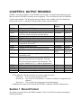
CHAPTER 6 OUTPUT RECORDS
85
Section 1 Record Format ......................................................................85
Section 2 Record Descriptions ................................................................86
6.2.1 GPGGA Record ........................................................................ 86
6.2.2 RTSOL Record ......................................................................... 87
6.2.3 GPAVL Record ......................................................................... 87
6.2.4 RTVEC Record ......................................................................... 88
6.2.5 RTSLE Record.......................................................................... 88
6.2.6 RTUTM Record......................................................................... 89
6.2.7 RTSIO Record .......................................................................... 90
6.2.8 RTSAT Record ......................................................................... 90
6.2.9 RTATT Record ......................................................................... 91
6.2.10 RTKAR Record........................................................................ 92
6.2.11 RTKDC Record........................................................................ 92
6.2.12 RTBIN Record ........................................................................ 92
6.2.13 GPVTG Record ....................................................................... 94
6.2.14 RTSTC Record ........................................................................ 94
6.2.15 FUGTAR Record ...................................................................... 95
6.2.16 RTVECEX Record..................................................................... 95
CHAPTER 7 RTDLL
97
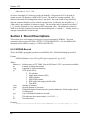
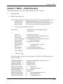
Section 1 RtDLL – Getting Started ........................................................... 97
Section 2 RtDLL – List of Functions ........................................................ 101
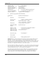
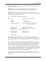
Section 3 RtDLL – Data Structures ......................................................... 107
iii
Version 3.15
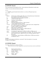
CHAPTER 8 RTENGINE
117
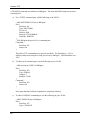
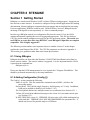
Section 1 Getting Started ................................................................... 117
8.1.1 Using RtEngine ...................................................................... 117
8.1.2 Adding Configuration (Config {}) ................................................. 117
8.1.3 Adding Ports (Port {}) .............................................................. 118
8.1.4 Adding Receivers (Master {} and Remote {}) ................................... 118
8.1.5 Adding Output and Command Ports (Output {} and Command {}) .......... 118
8.1.6 Intervals and Export Records ..................................................... 119
8.1.7 Controlling static and kinematic ................................................. 119
8.1.8 Exiting RtEngine .................................................................... 119
8.1.9 Setting the position of the Master ............................................... 119
8.1.10 Setting the ProcessMode ......................................................... 120
8.1.11 Moving Baseline Processing ...................................................... 120
8.1.12 Using distance and ambiguity constraints ..................................... 120
8.1.13 Azimuth determination........................................................... 121
8.1.14 Attitude determination........................................................... 121
Section 2 RtEngine – Input Configuration File............................................ 122
8.2.1 Config group ......................................................................... 123
8.2.2 Port group............................................................................ 124
8.2.3 Master/Remote group.............................................................. 125
8.2.4 Output/Command group........................................................... 126
8.2.5 Reject group......................................................................... 126
8.2.6 CFG file............................................................................... 127
Section 3 Sample Input Files................................................................ 127
8.3.1 Sample IN File ....................................................................... 127
8.3.2 Sample CFG File .................................................................... 129
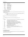
CHAPTER 9 USING SIOGPS
131
Section 1 Introduction and FAQ ............................................................ 131
9.1.1 What is SIOGPS? ..................................................................... 131
9.1.2 How can I use SIOGPS? ............................................................. 131
9.1.3 What is a port number and why is it needed?.................................. 132
9.1.4 What is a callback function? ...................................................... 132
9.1.5 Can I use Visual Basic? ............................................................. 132
9.1.6 What is structure packing and why is it important?........................... 132
9.1.7 How do I define what type of GPS receiver I am connected to? ............ 133
9.1.8 Do I need to configure the GPS receiver?....................................... 133
9.1.9 How and why would I re-broadcast data?....................................... 134
9.1.10 How do I set the static/kinematic status of the raw data?................. 134
9.1.11 What is a thread buffer and how do I use it? ................................. 134
9.1.12 Should I make my application multithreaded? ............................... 135
9.1.13 How and why should I log raw data? ........................................... 136
Section 2 Getting Started ................................................................... 136
9.2.1 Loading the DLL ..................................................................... 137
9.2.2 Opening SIOGPS library ............................................................ 137
iv
Table of Contents
9.2.3 Connecting to Ports ................................................................ 137
9.2.4 Filling in PORTINFOSTRUCT (for Serial ports) .................................. 139
9.2.5 Filling in NETPARAM (for Network ports) ....................................... 139
9.2.6 Filling in FILEINPPARAM (for using for reading from files) ................... 140
9.2.7 Filling in RXCFGPARAM (for connecting to a GPS receiver) .................. 140
9.2.8 Filling in RTKPARAM (for logging data from a GPS receiver) ................ 141
9.2.9 Datalogging settings................................................................ 141
9.2.10 Reading and decoding data ...................................................... 142
9.2.11 Method (a) — Using LogRtkData() function.................................... 143
9.2.12 Method (c) — Using byte-by-byte decoding ................................... 144
9.2.13 Other modes of usage: ........................................................... 146
9.2.14 Shutting the system down ....................................................... 146
Section 3 Function description ............................................................. 146
9.3.1 ConfigureReceiver .................................................................. 148
9.3.2 CloseSioLibrary...................................................................... 149
9.3.3 CloseSioLogFile...................................................................... 149
9.3.4 CloseSioPort ......................................................................... 149
9.3.5 DecodeOneByte ..................................................................... 149
9.3.6 EnableDisablePort .................................................................. 150
9.3.7 FillDecoderDefaults ................................................................ 151
9.3.8 FreeDecoder ......................................................................... 151
9.3.9 GetDataByte ......................................................................... 151
9.3.10 GetDataBuffer ..................................................................... 152
9.3.11 GetDataPortConnectInfo ......................................................... 152
9.3.12 GetDataBytesToBeRead .......................................................... 153
9.3.13 GetDataTotalBytes ................................................................ 153
9.3.14 GetLastSioError .................................................................... 154
9.3.15 GetThreadBufRecCount .......................................................... 154
9.3.16 GetThreadBufRecSize............................................................. 155
9.3.17 GetThreadBufSize ................................................................. 155
9.3.18 GpsShutDown ...................................................................... 155
9.3.19 InitSioLibrary....................................................................... 156
9.3.20 IsPortEnabled ...................................................................... 156
9.3.21 IsPortValid .......................................................................... 156
9.3.22 IsSerialPortAvailable .............................................................. 157
9.3.23 LogRtkData ......................................................................... 157
9.3.24 OpenDecoder....................................................................... 159
9.3.25 OpenSioLogFile .................................................................... 159
9.3.26 OpenSioPort ........................................................................ 159
9.3.27 ReadGpsPort ....................................................................... 160
9.3.28 ReadThreadBufData............................................................... 161
9.3.29 ReConnectDataPort ............................................................... 161
9.3.30 SaveSioLogFile ..................................................................... 162
9.3.31 SendDataBuffer .................................................................... 162
9.3.32 SendDataByte ...................................................................... 162
9.3.33 SendDataString .................................................................... 163
v
Version 3.15
9.3.34 SetAddMessage ....................................................................
9.3.35 SetDecoderOptions................................................................
9.3.36 SetSerialDataPort .................................................................
9.3.37 SetSioLogFileInterval .............................................................
9.3.38 SetStaticKinematicMode .........................................................
9.3.39 SetThreadBufSize..................................................................
9.3.40 SioWaitSec..........................................................................
9.3.41 StartRebroadcast ..................................................................
9.3.42 StopRebroadcast...................................................................
163
164
164
165
165
165
166
166
166
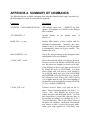
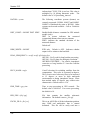
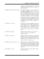
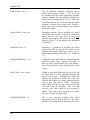
APPENDIX A SUMMARY OF COMMANDS
169
APPENDIX B ATTITUDE SOFTWARE
181
Section 1 Make Body Coordinates .......................................................... 181
Section 2 RtkNav.............................................................................. 187
INDEX
vi
189
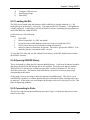
CHAPTER 1 INTRODUCTION
This chapter gives instructions on how to install RTKNav and includes trouble-shooting tips.
Descriptions of the various components of RTKNav are given, followed by an explanation of
some of the communication concepts used in this manual. RTKNav comes with the developer’s
kit documentation, which is the collective name for RtEngine, RtDll and SIOGPS. All of these
modules are explained below.
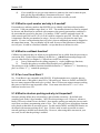
Section 1 What is RTKNav?
RTKNav is a real-time processing program that is used to obtain sub-metre, sub-decimetre or
centimetre accuracies. The accuracy obtained depends very much on the conditions of data
collection, receivers used and application dynamics. RTKNav requires raw data to work
(pseudoranges, carrier phase, etc…). It will not compute corrections from RTCM Type1. In
such a case, a DGPS receiver should be used.
Basically, RTKNav applications fall into three categories:
•
Forward RTK processing – The base station transmits raw data through a radio link
to the rover, where RTKNav is running. This is the master input stream. At the
rover, a GPS receiver is connected directly to RTKNav. This is the remote. The user
would normally use RTKNav to navigate or track the location of the vessel, vehicle
or aircraft.
•
Multi-remote Inverse RTK – RTKNav is running at the base station, where it is
connected directly to the master receiver. One to 20 mobile units are continuously
transmitting their raw data back to the base for processing. The base may either be
moving or static. RTKNav will plot the location of each of the mobile units. Their
solution can also be sent to another application.
•
Monitoring – RTKNav is tracking a number of near-stationary receivers to determine
their movement. In this application, accuracy is very important. RTKNav computes
the epoch-wise kinematic location of each, and RtStatic also computes a static fixed
integer position for even higher accuracy.
Currently, RTKNav supports the following GPS receiver inputs:
•
•
•
•
•
•
•
•
Ashtech AC12/G12/DG16/MACM/Z12/Z12DBEN/MACM_GSU1/MACM_GSU2
Canadian Marconi AllStar/SuperStar
Javad GRIL/OEM
Parthus XR6/XR7
Navcom NCT
NovAtel 2151/3151/OEM4/Millenium
Rockwell Jupiter
Trimble 4x00/SSx
Version 3.15
RTKNav offers a full-featured Windows interface. This interface comes with an easy-to-use
Configuration Wizard, plots up to 20 remotes, and shows the tracking status of each connected
receiver. A simple red-yellow-green light means that system operation can be checked by quick
inspection. For moving baseline applications, a bull’s-eye view is possible, along with range and
bearing display. Waypoint navigation is also supported.
For more information on RTKNav, please see 0.
Section 2 What is RtStatic?
Waypoint has added a major new feature called RtStatic to its RTKNav real-time kinematic
processing package. This option is aimed at near real-time deformation monitoring applications.
RtStatic uses Waypoint's GrafNav processing engine to provide Fixed Static solutions in near
real-time, while the standard RTK engine produces kinematic real-time solutions on a per epoch
basis. Filtering of the time history of the Fixed Static solutions produces millimetre level
coordinate changes on slow moving features such as slopes or dams.
Simultaneously, the standard kinematic engine processes the same data in real-time to monitor
fast moving events in standard kinematic fashion. On short baselines, single or dual frequency
receivers can be used with similar precision. Up to 20 base/remote combinations can be
processed on the same computer platform. Raw input or processed output data can be transferred
in real-time over serial or network connections.
Additionally, users have the ability to rebroadcast data collected in real-time over a network or
over the Internet, thus allowing other instances of RtStatic on other computers to process all, or a
subset of the data that you are processing. Furthemore, data can be rebroadcast so that other
instances of RtStatic on the same computer can be used to process a subset of the data.
For more information on RtStatic, please see Chapter 3 .
Section 3 What is RtEngine?
RtEngine is a command line version of RTKNav. It is usually called from the Windows DOS
Prompt. RtEngine does not have any of the graphics that RTKNav has, but with the command
interface, it is a very powerful tool. RtEngine requires Windows 95, 98, NT, 2000 or XP to run.
It will not run under DOS.
See Chapter 8 for a description of how to use RtEngine.
Section 4 What are RtDLL & SioGps?
RtDLL is the GPS differential processing engine used by RTKNav and RtEngine. Software
developers may be interested in this package, as it allows them to add full RTK processing
capabilities to their own software. The later chapters of this manual discuss how to access
2
Chapter 1 Introduction
RtDLL. Users must purchase the development kit in order to obtain the sample source code and
header files necessary to utilize the DLL.
SioGps is the serial/network communications DLL used by RtEngine, RTKNav and the GPS
Data logger. This DLL has many functions within it and can be used in a number of ways. For
instance, a user can collect GPS data using their own communications routines and use a
DecodeOneByte routine to unravel the necessary raw data logs in the GPS data. A user can also
use the serial and network communications routines to connect directly the GPS receiver. Like
RtDLL, the development kit must be purchased to access these routines.
See Chapter 7 for more information on RtDll and Chapter 9 for SIOGPS.
Section 5 What You Need To Start
In order to get RTKNav running, the following items are required:
•
•
•
•
•
•
Computer with RTKNav installed. See Section 6 for installation instructions. The
processor should be a Pentium or faster.
At least two serial ports. Unless TCP/IP data input is utilized, RTKNav requires one
serial port for each GPS receiver it is connected to (either directly or via a radio link). An
easy way to get started is to use a USB multi-port serial device.
For the first try, using a direct (serial) connection is easiest. This way any problems due
specifically to the radio link can be isolated later.
At least two suitable GPS receivers are also required. One is the master and the
remaining ones would act as mobiles (i.e. remotes). The receivers should have an open
view of the sky in order to work with RTKNav. Placing them in a window may not
provide enough satellites for navigation.
A serial port is also required if you wish to output serial records to another device. Note
that this can also be performed via TCP/IP (TCP mode only).
The hardware key must be connected to the parallel or USB port.
Section 6 Installing RTKNav
Installing RTKNav is quite simple, and can be done by performing the following steps:
1. Insert the CD into the drive. If you have downloaded the setup program from
Waypoint’s FTP site, then please note the directory containing the Setup.exe program
2. From the Windows Start Menu, select Run
3. Click on Browse, and move to the drive or directory containing Setup.exe (i.e. select
your CD-ROM drive for CD installation)
4. Select Setup.exe and press OK
5. Follow the instructions
6. For NT users, you must re-boot your machine before the hardlock drivers will take
effect. Users of Windows 9x and XP do not need to reboot.
3
Version 3.15
Section 7 Sentinel Hardlock Problems
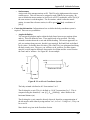
Currently, this product only works with two types of hardware key, both of which are
manufactured by Sentinel. The Sentinel parallel-port locks are beige colored, while the USB
keys are purple. Encoded in their memory is the key’s serial number, software type (i.e.
GrafNav/GrafNet, RtkNav, RtStatic, POSGPS, etc.) and version number. The memory may also
contain the demonstration status if applicable. The information on the Sentinel lock's memory
can be read using the Hardlock Upgrade Utility, which can be accessed from the software's
program group in the Start Menu.
There are currently no known compatibility issues with these hardlocks. The most frequent
cause of problems is due to drivers not being installed. The error message for such an error is
'FATAL ERR – Hardlock error! Unable to open Sentinel hardware lock driver – Install driver
(error code 12)'. In Windows 95/98, the hardlock will work without the drivers even being
installed. However, for Windows 2000 and NT, it is important that the drivers are installed, and
the system is restarted.
Another common cause of problems is an incompatible version number for the software type
between the processor and key. In this case, you will need to contact your dealer. This returns
one of two error messages, 'FATAL ERR – Hardlock error! Hardware key is intended for a
software version older than what is being used – reinstall older version or upgrade key'.
There has been a few cases where failed or intermittent locks have been encountered. These
usually return an error labeled 'FATAL ERR – Hardlock error! Waypoint hardware key not
found – Check printer port (error code 3)'. Test procedures have improved, but if the problem
occurs, the lock will need to be replaced. Note that an RMA number is required before a
shipment will be accepted. Please contact you dealer for instructions.
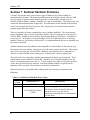
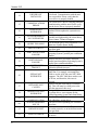
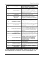
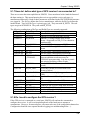
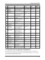
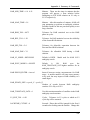
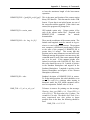
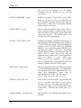
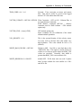
Otherwise, the error code number that is shown in the error message corresponds to the
following:
Table 1.1: Definition of Hardlock Error Codes
ERROR
CODE
0
1
4
ERROR MESSAGE
DESCRIPTION
SUCCESS
INVALID FUNCTION
CODE
See your language’s Include File for valid
API function codes. Generally, this error
should not occur if you are using a
Rainbow-provided interface to communicate
with the driver.
Chapter 1 Introduction
2
INVALID PACKET
3
UNIT NOT FOUND
4
ACCESS DENIED
5
INVALID MEMORY
ADDRESS
6
INVALID ACCESS
CODE
7
PORT IS BUSY
8
WRITE NOT READY
9
NO PORT FOUND
10
ALREADY ZERO
A checksum error was detected in the
command packet, indicating an internal
inconsistency. The packet record structure
may have been tampered with. Generally,
this error should not occur if you are using a
Rainbow-provided interface to communicate
with the driver.
The specific unit could not be found. Make
sure you are sending the correct information
to find the unit. This error is returned by
other functions if the unit has disappeared
(i.e. it is unplugged).
You attempted to perform an illegal action
on a word. For example, you may have tried
to read an algorithm/hidden word, write to a
locked word, or decrement a word that is not
a data nor counter word.
You specified an invalid Sentinel SuperPro
memory address. Valid addresses are 0-63
decimal (0-3F hex). Cells 0-7 are invalid for
many operations. Algorithm descriptors
must be referenced by the first (even)
address.
You specified an invalid access code. The
access code must be 0 (read/write data), 1
(read-only data), 2 (counter) or 3
(algorithm/hidden).
The requested operation could not be
completed because the port is busy. This can
happen if there is considerable printer
activity, or if a unit on the port is performing
a write operation and is blocking the port.
Try the function again.
The write or decrement could not be
performed due to a momentary lack of
sufficient power. Try the operation again.
No parallel ports could be found on the
workstation.
You tried to decrement a counter or data
word that already contains the value 0. If
you are using the counter to control demo
program executions, this condition may
occur after the corresponding algorithm
descriptor has been reactivated with its
activation password.
5
Version 3.15
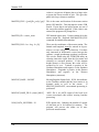
12
DRIVER NOT
INSTALLED
13
COMMUNICATIONS
ERROR
18
VERSION NOT
SUPPORTED
19
OS ENVIRONMENT
NOT SUPPORTED
20
QUERY TOO LONG
30
DRIVER IS BUSY
31
PORT ALLOCATION
FAILURE
32
PORT RELEASE
FAILURE
39
ACQUIRE PORT
TIMEOUT
42
SIGNAL NOT
SUPPORTED
57
INITIALIZE NOT
CALLED
58
DRIVER TYPE NOT
SUPPORTED
59
60
6
FAILURE ON DRIVER
COMMUNICATION
SERVER PROBABLY
NOT UP
61
UNKNOWN HOST
62
SEND TO FAILED
The system device driver was not installed
or detected. Communication with the unit
was not possible. Please verify that the
device driver is properly loaded.
The system device driver is having problems
communicating with the unit. Please verfiy
that the device driver is properly installed.
The current system device driver is
outdated. Please update the system device
driver.
The Operating System or Environment is
currently not supported by the client library.
Please contact Technical Support.
The maximum query string supported is 56
characters. Send a shorter string.
The system device driver is busy. Try the
operation again.
Failed to allocate a parallel port through the
Operating System’s parallel port contention
handler.
Failed to release a previously allocated
parallel port through the Operating System’s
parallel port contention handler.
Failed to acquire access to a parallel port
within the defined time-out.
The particular machine does not support a
signal line. For example, an attempt was
made to use the ACK line on a NEC 9800
computer. The NEC 9800 does not have an
ACK line, and therefore, this error is
reported.
Failed to call the client library’s initialize
API. This API must be called prior to the
API that generated this error.
The type of driver access, either direct I/O
or system driver, is not support for the
defined Operating System and client library.
The client library failed to communicate
with a Rainbow sytem driver.
The server is not responding; the client has
timed-out.
The server host is unknown. The server is
not on the network, or an invalid host name
was specified.
The client was unable to send a message to
the server.
Chapter 1 Introduction
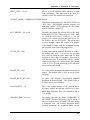
63
SOCKET CREATION
FAILED
64
NO RESOURCES
65
BROADCAST NOT
SUPPORTED
66
BAD SERVER
MESSAGE
67
NO SERVER RUNNING
68
NO NETWORK
69
NO SERVER RESPONSE
70
NO LICENSE
AVAILABLE
71
INVALID LICENSE
72
INVALID OPERATION
73
BUFFER TOO SMALL
74
INTERNAL ERROR
75
255
PACKET ALREADY
INITIALIZED
INVALID STATUS
The client was unable to open a network
socket. Make sure the TCP/IP or IPX
protocol is properly installed on the system.
Could not locate enough licensing
requirements. Insufficient resources (such as
memory) are available to complete the
request, or an error occurred in attempting to
allocate the needed memory.
The broadcast is not supported by the
network interface on the system.
Could not understand a message received
from the server. An error occurred in
decrypting (or decoding) a server message at
the client end.
Cannot communicate to the server. Verify
that the server is running. The server on the
specified host may not be available for
processing the request.
Unable to communicate with the specified
host. Network communication problems
encountered.
No server responded to the client broadcast.
There is no server running in the subnet, or
no server in the subnet has the desired key
connected.
All licenses are currently in use. Server has
no more licenses available for this request.
The license is no longer valid. License
expired due to time-out.
The specified operation cannot be
performed. Tried to set the contact server
after obtaining a license, or tried to call
FindFirstUnit function on a packet that
already has a license.
The size of the buffer is no sufficient to hold
the expected data.
An internal error, such as failure to encrypt
or decrypt a message being sent or received,
has occurred.
The packet being initialized was already
initialized.
An invalid status code was returned.
The Alladin (black) hardlock is no longer supported. Therefore, if you have such a key, then it
must be exchanged for one of the Sentinel keys. There may be an upgrade charge for this.
7
Version 3.15
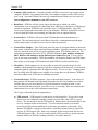
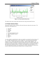
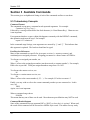
Section 8 Utilities
The following utilities are also included with the software:
•
Concatenate, Slice and Resample
A raw GPS data utility that can edit raw data files produced by RtkNav. If users choose
to log in the raw binary format of the GPS receiver, the files will have to be converted to
Waypoint’s format before this utility can be used.
•
GPB Viewer
This utility will allow you to view the raw binary data collected by the GPS receiver in
order to detect any problems. Measurement values and position records are among the
fields that can be viewed here.
•
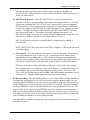
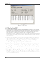
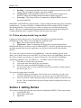
GPS Data Logger
This utility is included to facilitate GPS data logging directly from a variety of GPS
receivers under a Windows 95, 98, 2000, XP and NT environment. Features such as
tagging stations and satellite lock plots are included as well. Logging can be performed
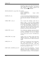
directly into Waypoint’s custom format. Refer to Table 1.2 for supported receivers.
Table 1.2: Receivers Supported for Data Logger
MAKE
CMC
Conexant
CSI
Garmin
Javad
Motorola
NAVCOM
NavSymm/
Parthus
NovAtel
Thales
Trimble
U-Blox
8
MODEL
Allstar
Superstar II
Jupiter
DGPS MAX
25 series
35 series
All models
VP Oncore
OEM GPS
XR5
XR6
XR7
OEM2
OEM3
OEM4
Real-Time
4000 series
(DAT)
4000 series (RT)
5700
SSx
Antaris
DATA LOGGING
WINDOWS WINCE
Chapter 1 Introduction
Section 9 What else is contained on the CD?
The CD Distribution contains the following directories (additional to the setup file):
• Hardlock
This directory contains the drivers necessary for Windows 2000, NT and XP installation.
All hardlock drivers should be installed automatically during installation.
• Geoid
This directory contains geoid files for U.S. (Alaska96, Geoid96, Geoid99, Geoid03),
Mexico97, Australia (AusGeoid93 and AusGeoid98) and the World (EGM96). These
files allow mean-sea-level (orthometric) heights to be computed using GrafNav and
GrafNet. Files are in the WPG (Waypoint Geoid) format. For Canada, files must be
downloaded from the Geodetic Survey Division of Geomatics Canada. Other regions of
the world are also available.
• ManualPdf
Contains this manual, as well as the MultiEngine manual, in Adobe Acrobat format.
Section 10 Communications definitions and concepts
The following section describes some of the terms used in the next Chapter. If you are
unfamiliar with terms relating to serial and network communication ports, this may be useful to
you.
When starting an RTKNav project, you will need to know a number of items relating to serial
comports and network ports, among other things. Some of these, especially those related to
networks, are briefly explained below.
NOTE: In the following discussion, the term Win32 will be used to denote Win95, Win98,
Win2000, Win XP and Win NT. RTKNav has been extensively tested on all of these operating
systems.
•
Assigned Port Number – RTKNav, RtEngine and SioGPS.DLL use an assigned port
number to reference a serial or network port. Assigned port numbers range 1 – 1023, and
they have no correlation to serial comports or network port numbers. Assignment is usually
sequential.
•
Comport (computer)- The Windows system defines a number of serial communications
ports, depending on what serial devices you have installed. Generally, you will have COM1
and COM2. Your mouse may use one of these. Serial boards or Serial - USB devices will
show in the Win32 system as COM ports. RTKNav is designed to read the Win32 system
and determine which COM ports you have and are available for reading measurement data
from your GPS receivers. COM ports are usually defined in the region COM 1 –
COM20.
9
Version 3.15
•
Comport (GPS receivers) – Currently virtually all GPS receivers have one or more serial
comports. RTKNav can communicate from your computer comport to either GPS receiver
port A or B Note that RTKNav has two-way communication with the receivers and will
send configuration commands to your GPS receivers.
•
Baud Rate – RTKNav will ask you to choose the data rate at which you wish to
communicate over your serial port. Baud rates from 4800 bits per second to 115200 bits per
second are supported. RTKNav will run reliably up to 115200 bps (baud). Your GPS
receiver must support the same baud rate as your computer. RTKNav will poll the receiver
to set its baud rate to the correct setting, providing the receiver supports that rate.
•
Network Port – RTKNav will send or read GPS data that has been broadcast over a
network. The term network port is used here to describe a communication port through
which a data stream is being sent over a local or wide-area network.
•
Network Port Number - Like COM ports, network ports are assigned numbers so that each
data stream is identified with an associated integer number. Network port numbers from 1 to
1024 are generally reserved for use by the operating system, FTP, Internet and so on. The
maximum port number allowed is 65356. RTKNav defaults to port numbers starting at
6001. RtkNav will attempt to assign different port numbers for you. You are free to
type in your own port numbers. These port numbers will uniquely identify each GPS binary
data stream or each output ASCII data stream from RTKNav to other network users.
•
IP Address – Each computer on a local or wide are network is given a unique set of 4
numbers which identify this computer to all other computers on the network. Local network
computers (nodes) will tend to have IP addresses such as 192.xxx.xxx.xxx. Computers that
have so-called static IP addresses are capable of receiving data over the Internet. RTKNav
uses these addresses in TCP mode to send data anywhere.
•
Network Protocol – RTKNav supports 3 types of network data protocol. Your choice of
data protocol will depend on the operating system that you have and whether you wish to
send the data over your local network or over the Internet to a remote location. Local
networks would be the network in your office or say on your ship. Wide are networks that
communicate all over the world on Internet connections.
The 3 types of network protocols supported are:
a) UDP protocol – UDP protocol is used strictly on local networks. If you wish to send
data to your own computer or another computer in your office, then UDP is a good
choice. If a data stream is sent on UDP protocol, then the data will automatically be sent
to every computer in the local network. To receive this data stream, you must be
receiving in UDP protocol and must be on the same port number as the sender. For
instance if RTKNav is asked to re-broadcast a serial data stream from a NovAtel GPS
receiver by UDP on port 5001, then every computer on the local network will receive
UDP data on port 5001. The receiver must specify UDP, port 5001 to get the data into
another instance of RTKNav running somewhere else on the network.
10
Chapter 1 Introduction
Note that in Win32 operating systems, UDP is always assigned an IP address of
255.255.255.255. This may not be true for UNIX-based systems. UDP should work on
Win95, 98, 2000 and NT.
b) MULTICAST protocol – Like UDP, MULTICAST is an ideal choice for local
networks. It is only meant for sending or receiving from computers near you. Note that
all protocols, including MULTICAST will “loop” network data to your own computer.
This means that you can use network ports to send data to another instance of RTKNav
on your own computer. MULTICAST like UDP sends data to every computer in a local
network. The difference between UDP and MULTICAST is that a MULTICAST user
must type in an IP address. This address is actually denoting a user group. All
MULTICAST Win32 users must join a group with an IP addresses of between 224.0.0.0
and 240.0.0.0. RTKNav defaults to a user group address of 234.5.6.7.
MULTICAST users must type in a group IP address, whether they are sending or
receiving data.
NOTE: MULTICAST may not work on some Win95 computers. UDP may be used in an
equivalent fashion.
c) TCP protocol – TCP may be used in either local or wide-area networks. Local network
users will probably not use TCP since in TCP, you must know the IP address of the
computer that you are sending data to. TCP is used to send data over the Internet and
must be used to send data outside your local network. In principle, this protocol will send
your data to any point in the world, which has a static IP address and is on the internet.
TCP users do not have to know an IP address if they are receiving data. The computer
that is sending data to you must know your local IP address. To obtain the IP address of
your computer, open a command line prompt by going to Windows Start Menu | Run…
Type “cmd” into the blank space and click OK. In the DOS window that appears, type in
“ipconfig /all”. A display should appear showing your local IP address.
•
Re-Broadcast Data – This functionality allows a user to collect GPS raw binary data from a
serial port and send this data over a local or wide area network to another window on your
computer, another RTKNav user in your local network (UDP or MULTICAST protocol) or
another RTKNav user in some other part of the world (TCP protocol). This allows multiple
instances of RTKNav to process the same data from the same group of GPS receivers. This
may be useful, if you want one copy of RTKNav to process data from your entire group of
GPS receivers, while another copy only examines data from a subset of your receiver group.
You might also find this useful, if you simply wish to have some other remote computer store
your raw binary measurement for future post-processing.
Note that RTKNav instances receiving data over a network can also re-broadcast this data to
other network ports.
11
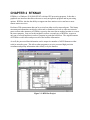
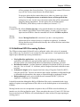
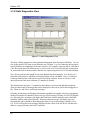
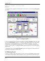
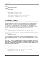
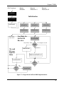
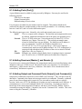
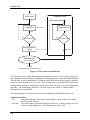
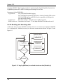
CHAPTER 2 RTKNAV
RTKNav is a Windows 95/98/2000/XP/NT real-time GPS processing program. It that has a
graphical user interface that allows the user to easily navigate the program and its processing
options. RTKNav also has the ability to support one base station receiver and one or more
remote station receivers.
Real-time GPS measurement data can be received on either serial or network ports. This binary
measurement information can also be re-directed (re-broadcast) to local or wide-area network
ports to allow other instances of RTKNav to process the same data at another location or even on
the same computer. One use for this might be to allow a second copy of RTKNav to process
only one of several baselines in order to examine its particular behaviour. The original instance
of RTKNav would collect and process all of the baseline information.
As well, the processed data information can be output in a number of ASCII formats to either
serial or networks ports. This allows other programs to receive processed high precision
coordinate and quality information either locally or by the Internet.
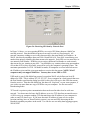
Figure 2.1: RTKNav Project
Version 3.15
Section 1 Getting Started
The following section describes step-by-step how to start using RTKNav.
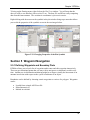
2.1.1 Running RTKNav
Before processing, the user must start a new project or open an existing project. RTKNav
initially creates two project files, an IN file and a CFG file. The IN file mainly contains
information about communication ports. The processing engine RtGpsX.dll uses the CFG file to
perform GPS processing functions. To get started, the user must first define the GPS receiver
types and communication parameters.
First-time users should review the following sections very carefully.
Steps to begin a new project and start real-time GPS processing:
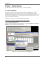
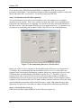
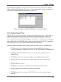
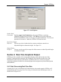
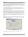
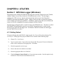
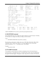
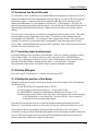
Step 1: Start up RTKNavRx.EXE
The figure below illustrates how to launch RtkNavRx.exe. Go to the Windows Start menu as
indicated. Choose either RtkNavR3 or RtkNavR20.
Figure 2.2: Using the Start Menu to Launch RTKNav.
14
Chapter 2 RTKNav
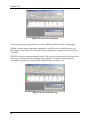
Note that in the above diagram, RtkNavR3 and RtkNavR20 are running on the same host
computer. Additionally, in this figure, RtkNavR3 is re-broadcasting its serial data over the
network using MultiCast protocol. RtkNavR20 is re-computing the project with the same data as
RtkNavR3. Using the network capability, RtkNavR3 and/or RtkNavR20 can use the same data
at many remote locations on your local or wide-area network.
When Should you use RtkNavR3 versus RtkNavR20?
Users who have purchased RtkNavR1 or RtkNavR3 should use RtkNavR3, as
RtkNavR20 takes up considerably more memory and CPU. RtkNavR20 should only be
used by if you have more than 3 remote GPS receivers on line.
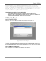
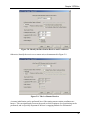
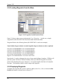
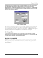
2.1.2 Start New Project
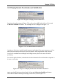
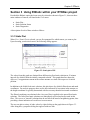
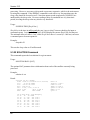
Step 2: Create a New Project
Select File | New Project and type a filename for your project. See Figure 2.3.
Figure 2.3: Start a New Project
The IN file will contain communication parameters necessary for data input and output. If you
have already defined an IN file for your project, then simply go to File | Open Project to load it.
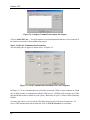
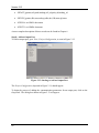
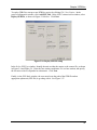
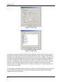
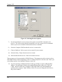
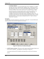
Step 3: Add Receivers to the Project
Next, a Configure Project window will be displayed. See Figure 2.4.
15
Version 3.15
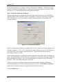
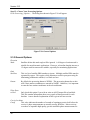
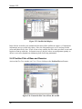
Figure 2.4: Configure Communication Input and Output
Click on Add GPS Unit… You will continue to use this button until the base receiver and all of
the remote receivers have been added to the project.
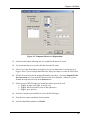
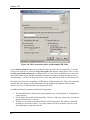
Step 4: Define the Communication Parameters
The next dialog box to appear is shown below, in Figure 2.5.
Figure 2.5: Serial Communication Parameters for your Computer
In Figure 2.5, we are assuming that you will utilize serial port COM1 on your computer at a baud
rate of 9600 in order to communicate with this GPS receiver. RTKNav will recognize any COM
port that Windows has available on your system. Baud rates of up to 115200 are allowed and are
reliable.
You may also choose to receive binary GPS data from a local or wide area network port. To
receive GPS measurement data by network, click on TCP/IP Network, as seen below.
16
Chapter 2 RTKNav
Figure 2.6: Receiving GPS data by Network Port
In Figure 2.6 above, we are requesting RTKNav to receive GPS binary data on a MultiCast
network protocol. Note that Multicast protocol can only be used on a local network. All
network computers wishing to receive this data must have the same MultiCast IP address. In
Win32, this must be an address between 224.0.0.0 and 240.0.0.0. Port 6001 is an arbitrary port
number that uniquely identifies this data stream to the network. Each GPS receiver must have its
own network Port Number. RTKNav tries to assign a different Port Number to each network
data stream for you, starting at port 6001. You should be very cautious about using port numbers
of less than 1024, as they are usually reserved for use by the computer's operating system. The
maximum port number is 65356. In MultiCast mode, all computers on a local network can use
the IP address given and the given port number to receive this data stream. NOTE: Win95
computers may not support MultiCast. You may have to use UDP or TCP.
UDP mode is exactly like MultiCast protocol, except that Win32 only defines one local IP
address for UDP. This is address 255.255.255.255. Every computer on a local network that uses
the Port Number typed into the dialog box (6001 in this case) will receive this GPS data stream
from the receiver. Note that like MultiCast, this data will “loop back” to your own computer, if
you wish to run more than one copy of RTKNav on your computer. See the note on ReBroadcasting below.
TCP mode is a point-to-point communication that can be used in either local or wide area
network. You do not need to know the IP address, to receive TCP data from an outside source.
A GPS receiver or computer sending TCP data must know the IP address of your computer in
order to send TCP data to you. If you know the static IP address of some user in a remote
location (and they have no firewall in their system), you can send GPS data using the ReBroadcast capability anywhere in the world. Use can also use our utility data logging program,
WLOG.EXE.
17
Version 3.15
Users can also replay GPB files through RTKNav to simulate the RTK processing with
previously collected data. Users must have the data in GPB format and have proper overlap with
master and remote files. See Section 2 for details on replaying GPB files.
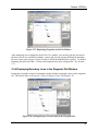
Step 5: Re-Broadcast the GPS Data (optional)
You can Re-Broadcast your serial or network data to your own computer or to a computer
anywhere on your network. This is very useful if you need some other user to simultaneously
process the same data that you are collecting. This user does not have to be hooked directly to
the GPS receivers. Only the original RTKNav has to be connected directly. For instance, let us
say that you are connecting your computer COM1 to the GPS receiver as indicated below.
Figure 2.7: Re-broadcasting Data over a Network Port
In this case, COM 1 of your computer is directly linked to the GPS receiver at a baud rate of
115200 bps. By re-broadcasting the data on a MultiCast IP of 234.5.6.7 on Port 6002, any
computer in the local network including the computer that you are working on will receive this
GPS binary data, provided that they join MultiCast group 234.5.6.7, Port 6002. If you rebroadcast all or some of your GPS receiver data, you can run other instances of RTKNav to
simultaneously process all or part of your survey on another window of your computer, another
computer on your local network or in TCP mode, another computer somewhere else in the world
(provided that they open a hole in their firewall security). Again, UDP protocol may be more
appropriate for some users. Note that you cannot rebroadcast data when replaying GPB files.
Step 6: Choose the Receiver Type
If the unit is your base station, identify it as such. Please see Figure 2.8.
18
Chapter 2 RTKNav
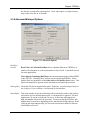
Figure 2.8: Identify the Base Station Receiver and Coordinates
Otherwise, identify the receiver as a remote unit, as demonstrated in Figure 2.9.
Figure 2.9: This is a Remote Receiver
A remote initialization can be performed here if the starting remote station coordinates are
known. This can significantly increase the speed at which centimetre level positioning can be
performed, and is especially important if the user is engaging RtStatic for deformation
19
Version 3.15
monitoring applications (see Chapter 3 for more information on RtStatic). Orthometric heights
can also be entered provided that there is complete geoid coverage of the area of interest. Refer
to Section 2.3.10 for more information about geoids in RTKNav.
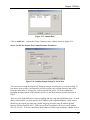
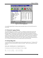
Step 7: Define the GPS Data Parameters
The next important step in configuring communication to this GPS receiver is to tell RTKNav
whether the data will be kinematic or static, and whether you intend to log this data to hard disk,
and at what data rate. It is also possible to configure either the primary or secondary GPS
receiver comports.
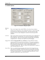
Figure 2.10: GPS Data Parameters
Figure 2.10 illustrates the final step in adding a GPS receiver. Some receivers have primary and
secondary comports – A, B, C, or D. Data intervals can be as high as you wish. The dialog box
does allow you to type a custom output data interval. Typical data intervals for real-time
processing are from 1 to 10 Hz.
As previously mentioned, it is important to define whether the data will be static or kinematic in
nature. Most applications will have static base stations but for moving baseline mode, define the
base station data as kinematic. Also, for most applications, the remote receivers will also be
kinematic. This is the default setting for remote units.
Finally, if you choose to log data to disk, it can be stored in either Waypoint’s GPB binary
measurement format, or it can be stored byte by byte as a raw file. The GPB File or Raw File
modes may be useful if you plan to post-process the data for later analysis.
Click the Finish button.
20
Chapter 2 RTKNav
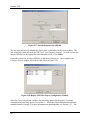
Repeat Step 3 through Step 7 to add extra receivers (base or remotes) until you have finished
adding and configuring all of your GPS receivers. Upon completion of this task, the dialog box
seen in Figure 2.4 should look like that shown in Figure 2.11.
Figure 2.11: Base and Remote GPS Receivers have been added
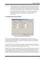
2.1.3 Adding Output Ports
RTKNav allows you to send processed coordinate and quality information for each baseline out
either a serial or network port. RTKNav also allows for multiple output ports, as well as socalled command ports. Command ports are two-way ports that an external user can utilize to
receive data from and send commands to RTKNav. For instance, a user logged into a TELNET
session will be able to start RTKNav from a remote location and send it a rich list of commands.
In the following, however, we will limit the discussion to one output port.
Output ports send a combination of the following ASCII records out a serial or Ethernet port:
•
$RTSOL,gpstime,R#,phi,lamda,ht,sdh,sdv,ve,vn,vh,nsats,S/K,qf,dd_dop,status
status: 0-no solution, 1-single point, 2-DGPS, 3-RTK, 4-RTK(errors), 5-estimated RTK
•
$RTSLE,gpstime,R#,phi,lamda,ht,sdh,sdv,ve,vn,vh,nsats,S/K,qf,dd_dop,status,F/L,
CaRms,L1Rms
•
$RTUTM,gpstime,R#,east,north,ht,zone,sdh,sdv,nsats,S/K,qf,dd_dop,status,F/L
•
$RTSAT,gpstime,R#,nsats,prn1,elev1,az1,amb1,lock1,prn2,elev2,az2,amb2,lock2 ...
•
$RTBIN,NBytes,hex values ....
•
$RTSIO,gpstime,age,latency,num,M,time,nsats,R1,time,nsats,R2,time,nsats ...
•
$RTKDC,gpstime,AllPF,ambPF,Rel,relPF,num_intersections
•
$RTKAR,gpstime,R#,rms,rel,pass_fail(P/F),fltfixed,sec_used,sec_engaged,avg_sats,
freq(S/D)
21
Version 3.15
•
$RTATT,gpstime,roll,pitch,heading,roll_sd,pitch_sd,heading_sd
•
$RTVEC,gpstime,R#,east,north,up,sdhz,sdv,S/K,nsats,qf,status
•
$GPGGA: see NMEA document
•
$GPVTG: see NMEA document
A more complete description of these records can be found in Chapter 6 .
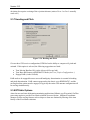
Step 8: Add an Output Port
To add an output port, go to View | Project Configuration, as seen in Figure 2.12.
Figure 2.12: Starting to Add an Output Port
The Project Configuration, depicted in Figure 2.11, should appear.
To begin the process of adding the communication parameters for an output port, click on the
Output tab. The dialog box shown in Figure 2.13 will appear.
22
Chapter 2 RTKNav
Figure 2.13: Output Data
Click on Add Port… to open the Output Communication window, shown in Figure 2.14.
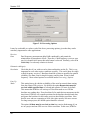
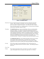
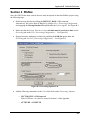
Step 9: Define the Output Port Communications Parameters
Figure 2.14: Sending Output Strings by Serial Port
You can choose to send the output ASCII data to serial or network ports, or to write to disk. If
you choose write to disk, your output file will be saved in your working directory and will be
given the same name as your project, with an optional file prefix. For more information
regarding the other options in this window, please see the discussion on network protocols in
Step 4.
There are some slight differences between sending and receiving data on Ethernet ports. To send
data by network port, you must specify the IP address of the output destination. In the case of
MultiCast, once again you must join a MultiCast group all on the same IP address defined
between 224.0.0.0 and 240.0.0.0. UDP users on Win32 machines will have to use IP address
255.255.255.255. TCP users must know the IP address of their target computer, whether local or
23
Version 3.15
wide area. For wide area networks, this is typically a static IP address. The network mode must
also be set to client or server if TCP/IP mode is selected.
Clicking the Next button brings up the final step in the process.
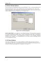
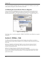
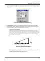
Step 10: Select the Output ASCII Record Types
To add a selection of ASCII records for output, select a record type. Before clicking the Add
button, be sure to select the interval on which you want this record outputted. See Figure 2.15.
Figure 2.15: Sending Output Data by Network Port
Click the Finish button to complete the addition of your output port.
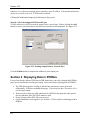
Section 2 Replaying Data in RTKNav
If a user has already collected GPS data in GPB format, they can relay it through the RTKNav
processor to simulate the real-time processing. Some notes about replaying data in RTKNav:
•
•
•
•
24
The GPB files must have overlap so that the base and remotes can be processed
differentially. RTKNav can handle data gaps. If necessary use the Concatenate, Slice
and Resample utility.
There must be at least one valid ephemeris file (EPP file) that spans the entire period.
Precise ephemeris files (SP3 files) cannot be used.
Events in station files (STA files) are not used.
Geoid undulations can be applied. See Section 2.3.10 for details on utilizing geoids in
RTKNav.
Chapter 2 RTKNav
To replay GPB files, start up a new RTKNav project by clicking File | New Project. In the
project configuration window, click Add GPS Unit. In the GPS Communication window, select
Replay GPB File, as shown in Figure 2.16 below. Click Next.
Figure 2.16: Replay GPB file setup
In the Select GPS Type window, identify the unit as either the master or the remote file, as shown
in Figure 2.8 and Figure 2.9. Enter the base station coordinates if it is a base station, and specify
the elevation value as ellipsoidal or orthometric. Click Next.
Finally, in the GPS Mode window, the user must locate the path of the GPB file and an
appropriate ephemeris (EPP file) to go along with it. See Figure 2.17.
25
Version 3.15
Figure 2.17: Locate the path of the GPB file
The user must also specify whether this data is static or kinematic for the receiver added. The
user should also check the mode in GPB Viewer (see Chapter 4 Section 2 ) as well to make sure
that the GPB file has the appropriate static/kinematic mode. Click Finish.
Repeat the process for the other GPB files to add them to the project. Once complete, the
Configure Project window will look like that shown in Figure 2.18.
Figure 2.18: Replay GPB Files Project Configuration Window
Select the Processing tab and configure the processing options for the project. For more
information on processing options, see Section 3 . Select the Output tab and define different
methods/formats of output. For more information on outputting data, see Section 2.1.3 . The
26
Chapter 2 RTKNav
number of data buffers must be increased when replaying data. Otherwise, the project will stop
processing prematurely. See Section 2.3.4 for more details.
Section 3 Options
2.3.1 GPS Processing Settings
The processing engine that provides RTKNav with coordinate information is called RtGPsx.dll.
RtGps.dll is capable of processing the following ways:
•
•
•
Float Code/Phase – no ambiguity determination; accuracy: sub-metre to decimetre
On-the-Fly Ambiguity Determination – kinematic ambiguity resolution (KAR) with
code/phase measurements; accuracy: centimetre level. This can be invoked for either
single or dual frequency measurements
Code-Only Processing – accuracy: 1 to 5 metres
The default processing mode for RTKNav is single frequency float code/phase, with the base
station being considered static and the remotes being considered kinematic.
Users may need to change these default settings if they wish to achieve any of the following:
•
•
•
•
•
•
•
Dual frequency processing
Use of on-the-fly kinematic ambiguity resolution
Use of code-only processing
If you wish to change the time allowed for which data must be received from all remotes
before processing is allowed.
Moving baseline processing
Heading and pitch determination
Use of RtStatic DLL for a fixed static solution
Step 11: Choose Your Processing Configuration
To view the Configure Project dialog box, go to View | Project Configuration… Then, to view
the processing settings, click on the Processing tab. See Figure 2.19.
27
Version 3.15
Figure 2.19: Processing Options
It may be worthwhile to explore each of the above processing options, given that they can be
extremely important for some applications.
Receiver
Data
Dual frequency measurements help KAR considerably, and permit the
minimization of ionospheric effects. Therefore, if dual frequency receivers were
used, it is beneficial to ensure this radio button is selected. Similarly, select C/A
Code Only if a code-only solution is desired.
Kinematic Ambiguity
Resolution
Check this box if you wish to resolve phase ambiguities on the fly. This is very
important for users who require centimetre accuracy. This can be done for single
or dual frequency receivers. Baselines should be as short as possible for optimal
reliability; less than 4 km for single frequency and less than 10 km for dual
frequency. More related options are available under Processing | Options.
Line-Up
Mode
This setting has to do with the availability of the serial or network data coming
from the remote GPS receivers. By default, the option Remote data must be
received within specified time is selected and contains 250 msec by default.
This means that RTKNav will wait up to 250 milliseconds to see if all the
baselines are sending data. If any baselines fail to send their measurements in this
time frame, RTKNav will compute positions for the baselines that did send data,
and ignore the baselines for the remote receivers that failed to send data. Note
that for users who are computing at 10Hz, this value must be 100 msec at most.
For long-term projects, the default option should be selected.
The option All data must be received on time has a major disadvantage if you
are in a project and one GPS receiver fails to send data. In this case, RTKNav
28
Chapter 2 RTKNav
will not compute data for any baselines. If you expect some remote GPS receiver
to go off-line for any reason, then use the default option.
For projects where the base station data arrives either very latent or at a lower
interval, the Extrapolate master to minimize latency within specified time
setting may be used. In such cases, the master station data will be extrapolated
using time history information. For this option, the user defined option
EXTRAPOL_EPOCHS may need to be added (see Section 2.3.7 ).
Processing
Configuration By default, Manual Start-up is selected and should not be changed unless the
user wished to run RTKNav from a DOS prompt. In such a case, select this
option and run RTKNav from the command line like this: RTKNav myfile.in
Moving
Baseline
Ensure Moving Baseline ON is checked if you have a moving baseline
application such as a ship-to-buoy(s) or airplane-to-airplane(s). In addition,
moving baseline users should ensure that they have define their base station data
as kinematic, not static.
2.3.2 Additional GPS Processing Options
The GPS processing engine RtGpsx.dll can be configured with a wide variety of commands.
Some of these are very useful or even essential for some applications. Some applications that
might require additional processing commands are:
•
•
•
•
Moving Baseline applications – any ship to buoy(s) or airplane-to-airplane(s)
applications will require the moving baseline option to be turned ON. In addition,
moving baseline users should define their base station data as kinematic, not static.
Deformation analysis – perform Kinematic Ambiguity Resolution (KAR) at given time
intervals. New to version 3.11 is RtStatic, which computes fixed static solutions in near
real-time.
Orthometric heights can be computed real-time using a Waypoint Geoid file (WPG)
using the geoid32.dll. The user can enter the base station coordinates in ellipsoidal height
or orthometric height and have the output as ellipsoidal height or orthometric height.
Bad pseudoranges can be rejected with the user command REJECT_PSR (see
Appendix A Summary of Commands)
It should be noted that although the RtGpsx.dll Kalman filter can be commanded with a large
number of options, most applications will be able to use the default options as set internally by
RTKNav.
Moving baseline users are an important exception to this, as RTKNav must be told that you
intend to use it in Moving Baseline mode. Please remember that once a IN and a CFG file have
been created and saved, RTKNav will read and adopt all values in these files upon opening an
existing project.
29
Version 3.15
Step 12: Choose Your Processing Options
Go to Processing | Options… The dialog box shown in Figure 2.20 will appear.
Figure 2.20: General Options
2.3.3 General Options
Elevation
Mask
Omit
Satellites
Datum
Write Data
to Disk
Satellites below this mask angle will be ignored. A 10-degree elevation mask is
suitable for most kinematic applications. However, as baseline lengths increase, a
15-degree mask becomes more suitable, especially for monitoring applications.
This is a list of satellite PRN numbers to ignore. Multiple satellite PRNs must be
separated by spaces. This option, while sometimes useful in post-processing for
eliminating problematic satellites, is of little use here.
By default, the processing datum is WGS84. This processing datum also works
well if base station coordinates are entered in NAD83. Otherwise, it is important
to enter the base station coordinates in the selected datum.
Only check this option if you wish to write an ASCII output file to hard disk.
This file contains information about every epoch of data processed for each
baseline. A more detailed explanation of this is given in a later section.
Carrier Locktime
Cutoff
This value indicates the number of seconds of continuous carrier lock before the
receiver’s phase measurements are actually used by RTKNav. Most receivers,
even those of reputable high quality, put out unreliable phase measurements for
30
Chapter 2 RTKNav
the first few seconds after acquiring lock. Users who require very high accuracy
may wish to raise this to 10 seconds.
2.3.4 Advanced/Extrapol Options
Figure 2.21: Advanced Options
Bad Data
Control
Reset Filter At Unfixable Bad Data forces a Kalman filter reset if RTKNav is
unable to fix bad phase or code measurements or loss of lock. It should be left on
for most applications.
Write Epochs Containing Bad Data writes measurement epochs with bad DOPs
to the OUT file. Normally, these outliers are just ignored by RTKNav. Some
quality filters are adjustable via the Stdev Above and Quality Above boxes. This
option can normally be ignored unless data analysis is required post-mission.
Moving Base Check this ON for moving baseline mode. If this box was selected previously in
the Configure Project window, it will already be checked here.
Data Buffers This is the number of epochs of data that will be searched in order to line up base
and remote receiver measurement epochs. It can normally be ignored. For most
applications, 30 epochs is sufficient. However, if data rates and latencies are
high, this number may need to be increased. For users replaying GPB files, this
number must be increased, depending on how much data is being replayed. If the
replayed data stops unexpectedly, the user must increase this number to allocate
more buffers to be read.
31
Version 3.15
2.3.5 KAR Options
Figure 2.22: Kinematic Ambiguity Options
Minimum
Time
Cube Size
These are the length of times which RTKNav will perform float code/phase
solutions before attempting to resolve ambiguities on the fly. Users in poor GPS
environments may want to increase these times. The time needed for a dual
frequency receiver to resolve ambiguities can often be lowered in good GPS
conditions.
These are the regions of space that will be searched for the correct combination of
phase ambiguities. Decreasing these sizes reduces the likelihood of finding the
correct intersection. However, increasing them will significantly increase KAR
computation times. Normally, these options do not need changing.
Engage KAR Should the Engage KAR Every n (minutes) be selected, RTKNav will also
engage upon loss of lock and at the start of the data. This option is preferable to
many users in that it provides some level of protection against a bad KAR fix. If
KAR calculates the wrong solution, it will be completely independently
recomputed n minutes later. This is in contrast to the default option, in which it is
only recalculated upon loss of lock.
Search Filter These are considered advanced options, and only need to be changed by users
with experience using KAR. The KAR search interval controls how often KAR
performs a search. By default, this is every 30 seconds for single frequency and
15 seconds for dual frequency. For specialized applications that need very fast
ambiguity resolution, these values can be lowered.
32
Chapter 2 RTKNav
Data Filter
This data interval is how often KAR stores an epoch in memory. KAR will store
up to the Maximum Time (e.g. 30 minutes) in memory for both the master and
remote. Therefore, lowering this number will cause more memory to be used. It
will also slow down processing. However, KAR solution times and reliabilities
can be improved by lowering this value. The default value is 5 seconds, but users
can see improvements by lowering the value to 1 second. Data sets that are
improved tend to be those with “white noise” carrier phase characteristics.
Carrier data sets that have very systematic errors tend not to see any
improvements.
2.3.6 Standard Deviation Options
Figure 2.23: Standard Deviation Options
These indicate the a priori standard deviations applied that give weights to the various
measurements used in the Kalman filter. The rejection tolerance values are used to determine
when the filter should reset itself if it is not able to fix measurements that have post-filtering
errors above the given tolerances.
Using realistic values for the code and carrier standard deviations will improve float solution
convergence. For instance, many narrow correlator receivers have a C/A code measurement of 1
to 3 metres, which is much lower than the default value of 7 metres.
Normally, users do not have to change these values. In extreme GPS environments, it may be
useful to give more weight to the code measurements and less weight to the phase measurements.
Tracking sounding rockets is an example of this. These carry single frequency receivers to
heights of 1000 km. Changing the phase to 0.20 m and the code to 2.0 m dampens the effects of
uncorrected atmosphere on the phase measurements. Note that raising the L1 phase standard
33
Version 3.15
deviation also requires a raising of the rejection tolerance (ratios of 4-to-1 or 5-to-1 normally
work well.)
2.3.7 Heading and Pitch
Figure 2.24: Heading and Pitch
Given a three GPS receiver configuration, RTKNav has the ability to compute roll, pitch and
azimuth. If this option is selected, the following suggestions are listed:
•
•
•
Turn Moving Baseline ON (via the Advanced/Extrapol tab)
Turn Base and Remote to KINEMATIC Mode (via View | Project Configuration…)
Engage KAR (via the KAR tab)
KAR needs to be engaged because successful ambiguity determination is essential in heading
and pitch determination. KAR cannot engage unless the data is set to KINEMATIC, and the
moving baseline option must be engaged, as typically the entire GPS antenna configuration will
be moving simultaneously.
2.3.8 RTStatic Options
Aimed at near real-time deformation monitoring applications, RtStatic uses Waypoint's GrafNav
processing engine to provide Fixed Static solutions in near real-time. Millimeter coordinate
changes on slow moving features such as slopes or dams are obtained by filtering of the time
history of the Fixed Static solutions.
34
Chapter 2 RTKNav
Figure 2.25: RtStatic Option
Data Interval This value indicates the processing interval used to calculate the fixed static
solution. Thirty seconds is a good value, as it is not generally beneficial to
process static data at a higher rate than this. Processing static data at a higher
interval will often produce over-confident statistics, or cause an incorrect solution
to pass when it would have otherwise failed.
Time Span
The Initial Position time is the time that RtStatic will use to calculate the first
fixed static solution. This solution is used as the benchmark from which all
subsequent solutions are compared. Generally, this time should not be lowered,
as the initial position should be computed as accurately as possible. Alternatively,
if the coordinates of the remote receiver are initially known they can be directly
entered when adding the remote receiver to the project (see Figure 2.9). All other
fixed static solutions will be subtracted from this one to determine if slow
movement is present. Therefore, it is imperative that the initial solution is correct.
The Initialized Position time is the amount of data that will be used to compute
fixed solutions after the initial position. The default value is 60 minutes.
Lowering this value too much can potentially cause erroneous fixes. Single
frequency users may wish to raise this value under questionable GPS conditions.
Overlap
Filter Time
Window
This is the percentage of epochs that RtStatic will re-use from its previous
solution in the solution of the next fixed static solution. This should generally be
left at zero.
This constant is the amount of time used in the low pass filter to smooth the
results. Reasonable filter time constant values range from 12 to 24 hours.
35
Version 3.15
2.3.9 User Defined Options
There are numerous commands that can be sent to RtGPsx.dll. The User Defined options are all
listed in the dialog box below, along with help in the Command Information box. Review the
attached Appendix for a description of the commands that be added. These are generally used to
modify commands that are not normally used. See Figure 2.26.
Figure 2.26: User Defined Options
ISSUE_KAR_TIME is an example of a user-defined command. This particular command is
very useful in deformation analysis, where a static or near-static baseline must be continuously
determined to high accuracy. This command forces RTKNav to re-do kinematic ambiguity
resolution every n minutes. It is recommended for any users who wish to retain high precision
for very long periods of time.
2.3.10 Geoid Options
This feature will allow the user to compute orthometric heights while processing real-time or
when replaying a GPB file. It is important that the user has a valid WPG file that spans the area
of interest so that the geoid height can be computed. See Figure 2.27.
36
Chapter 2 RTKNav
Figure 2.27: Geoid Options
Enable Geoid
Corrections Enabling Apply Geoid Undulations will prompt RTKNav to calculate
orthometric heights when processing. Click Browse to locate the path of the
WPG file that RTKNav will use as a source of geoidal undulations. The file must
span the area of interest. Otherwise, RTKNav will return an error.
Base Station Height
Reference
The user may select whether their base station coordinates entered were
ellipsoidal height or orthometric height. See Figure 2.8.
Output Remote
Height as
The user can also specify the output for all the remotes as either ellipsoidal height
or orthometric height.
Section 4 Real-Time Graphical Output
RTKNav provides a number of text and graphical displays which indicate the state of the
program’s communication parameters, the coordinates of the baselines and the state of the
measurements with respect to each baseline. In addition, there are a variety of waypoint
calculations and plots available for real-time high precision navigation to pre-determined points
and boundaries.
2.4.1 Start Processing Real-Time Data
Assuming all of your serial and network connections have been made properly, RTKNav will
start processing on Processing | Start Processing or click on the icon with the green circle, as
shown below in Figure 2.28.
37
Version 3.15
Figure 2.28: Start Processing Data
Note that prior to processing, the receiver icons are RED to indicate no data is being logged.
RTKNav will now send configuration commands to each GPS receiver at the baud rates you
have chosen. If the GPS receivers respond to these configuration messages, the icons will turn
YELLOW.
If RTKNav receives measurement data from all of the receivers and ephemeris data from at least
one receiver, baseline solutions will begin to be computed. If a baseline solution has been
successfully computed, the icons will turn GREEN as shown in Figure 2.29.
Figure 2.29: Successful Start-Up
38
Chapter 2 RTKNav
2.4.2 Display Remote Coordinates and Satellite Info
Figure 2.30: Prepare to Display Data for Remote #1
Note that in the toolbar image in Figure 2.30, we have selected R1 in the list box. We then hit
the Receiver Solution tool button. The resulting text box is displayed in Figure 2.31.
Figure 2.31: Coordinates Remote baseline #1
Coordinates of the above include latitude, longitude and height of the remote antenna, as well as
delta east, north and up with respect to the base station. In Moving Baseline mode, only the
Local Level coordinates are meaningful and of high accuracy due to the nature of relative
positioning.
We can also display locktime, azimuth and elevation information for each baseline as depicted in
the next set of images.
Figure 2.32: Prepare to Display Satellite Info on Remote Baseline #1
Again, note that R1 has been selected in the list box and the Receiver Satellite tool button.
These choices add the following text display to the screen, seen in Figure 2.33.
39
Version 3.15
Figure 2.33: Satellite Info Display
In the list box seen above, the azimuth and elevation of the satellites are shown. Of importance
in kinematic surveys are the lock values. Here, the lock number goes to 255 and stays at this
value until phase lock is lost. If lock is lost on any satellite, the lock value goes back to zero and
begins to count up with time. In dynamic surveys, the lock values are an important quantity to
observe as accuracy depends on continuous phase lock being maintained.
2.4.3 Position Plots of Base and Remotes
Activate the Plot View window via View | Plot or clicking on the Position Plot tool button.
Figure 2.34: Zoomed In Plot View of Base, R1 and R2
40
Chapter 2 RTKNav
To bring up the floating menu, right-click on the Plot View window. You will note that the
above is really a zero baseline, with a scale of 2 cm. The base, R1 and R2 are really computing
data from the same antenna. The variation in coordinates is just receiver noise.
Right-clicking with the mouse on the symbols in the plot window brings up a menu that allows
you to edit the properties of the symbols as seen in the two images below.
Figure 2.35: Changing Properties of the Plot Symbols
Section 5 Waypoint Navigation
2.5.1 Defining Waypoints and Boundary Plots
RTKNav allows you to load a list of waypoints and/or enter and edit waypoints interactively.
These are pre-determined points that you may wish to navigate to or alternately avoid in realtime. Another use in deformation monitoring might be to inspect visually the movement of an
antenna in real-time with respect to the a priori coordinates of an object.
Boundaries can be defined by choosing certain waypoints as vertices of a polygon. Waypoints
can be:
•
•
•
Loaded from a simple ASCII text file
Edited interactively
Marked in real-time
41
Version 3.15
2.5.2 Loading Waypoints from the Menu
Figure 2.36: Waypoints Loaded from the Menu
Figure 2.36 shows what occurs on selecting the View | Waypoints…. In this case, a simple
waypoint file called WAYPNT.DAT has been loaded from the hard disk.
Waypoint files have the following format (WAYPNT.DAT is used as an example):
Name latitude (degrees minutes seconds) longitude (degrees minutes seconds) *(optional)
test1 50 58 44.500000000009 -114 0 42.599999999982,*
test2 50 58 46.500000000016 -114 0 43.599999999998
test3 50 58 48.499999999997 -114 0 44.600000000065,*
test4 50 58 40.499999999996 -114 0 40.600000000001,*
new 50 58 43.455012698966 -114 0 42.012714166015
hugh 50 58 42.998050950986 -114 0 42.017246776385
Note that the * is used to designate the vertex of some point defining a boundary. RTKNav will
join these points with lines to indicate boundary limits, provided the waypoints are actually
points on the boundary that you are interest in. An example might be the limits of an airplane
test range. This boundary could be used for range safety purposes.
2.5.3 Displaying Waypoints
To display the waypoints that you have loaded or added, select View | Plot or click on the Plot
Position tool button, as shown below in Figure 2.37.
42
Chapter 2 RTKNav
Figure 2.37: Displaying Waypoints in the Plot Window
After displaying your waypoint list in the Plot View window, you can also join any two lines in
the above plot or you can define boundary vertices and join any polygon defining the boundary.
Be sure to enter your polygon vertices in order to define the boundary plot correctly. To define a
boundary plot make sure that a * follows the longitude entry in the waypoint file. See Section
2.5.1 .
2.5.4 Displaying Boundary Lines in the Waypoint Plot Window
Displaying a boundary consists of joining the points defined as polygon vertices in the waypoint
list. This can be done via Waypoints | Connect Polygon Points. See Figure 2.38.
Figure 2.38: Joining Polygon Vertex Points in the Waypoint List
43
Version 3.15
You now have defined a boundary using your current waypoint list. Similarly, any two points
can be joined via Waypoints | Draw Line Between Selected.
2.5.5 Marking the Current Remote Point as a Waypoint
If you are interested in marking points as you go, you may mark the current remote receiver
position as a new waypoint. This may be useful, if you want to save the coordinates of any
particular point for some reason. Again, use the Waypoints | Mark… as shown in Figure 2.39.
Figure 2.39: Marking a Point
In the figure above, it can be seen that R1_CURRENT_POSITION is now defined as a waypoint
and plotted.
Section 6 RTKNav - FAQ
The following FAQ (Frequently Asked Questions) describes some problems or questions a
typical user may encounter while learning how to use RTKNav for data collection and real-time
processing.
Q: How do I toggle the static/kinematic flag for receivers when processing in real-time?
A: In the Receiver Status window, right-click on the desired receiver and select static or
kinematic from the pop-up menu.
Q: How do I change the project so that the master station is moving?
A: To use the moving baseline option for processing your GPS Data, go into the Processing >
Options menu and into the Advanced tab options. The moving baseline option is the second
option in this window.
44
Chapter 2 RTKNav
Q: How do I know if my receivers are collecting data?
A: The red lights in the receiver status window should turn from red to yellow to green when
everything is working properly, and you should also be able to see that the receivers have locked
onto satellites in the Satellite Data View windows. If in doubt, you can always use wlog.exe and
test to see if your receivers and serial cables/COM ports are connected properly.
Q: I chose the wrong settings in the project and/or processing configuration. Is there any way to
change the options while processing?
A: At this time, changing the configuration options while processing has been disabled.
Q: Should I be modifying the standard deviation and KAR (Kinematic Ambiguity Resolution)
options and tolerances?
A: In general, it is not recommended that you change the default options for these two groups of
options since RTKNav is designed to reset the filter when data is really bad. It is suggested that
these options only be changed during post-processing in software like GrafNav, unless you have
a-priori information about your data.(e.g. you know your C/A code measurements will be good)
Q: What happens if I start processing, stop, and then start again? Will my files be appended or
overwritten?
A: Upon restarting processing, your raw GPS data files (in .gpb format) will be overwritten.
Unfortunately, the Receiver Status will show that the total number of epochs recorded is the
amount from the previous processing plus the current number of records if you start, stop, and
restart processing. It is definitely not recommended to try this since RTKNav has and might
crash if you restart processing.
Q: Why am I getting the following error message, "Error: Hardware key not found, check printer
port"?
Figure 2.40: Hardware key not found error
A: A number of things can cause this error message. It cold be that your hardware lock is not in
the printer port, your hardware key is loose and not properly connected in the printer port, the
hardware key has not been burned properly, the hardware lock drivers are not installed, or the
hardware lock is faulty. If you are getting the error message and your hardware key is properly
connected to the printer port with the proper drivers installed, please contact the Waypoint
Products Group, NovAtel Inc. for information.
45
CHAPTER 3 RTSTATIC
Section 1 What is RtStatic?
Waypoint has added a major new feature called RtStatic to its RTKNav real-time kinematic
processing package. This option is aimed at near real-time deformation monitoring applications.
RtStatic uses Waypoint's GrafNav processing engine to provide Fixed Static solutions in near
real-time, while the standard RTK engine produces kinematic real-time solutions on a per epoch
basis. Filtering of the time history of the Fixed Static solutions produces millimetre level
coordinate changes on slow moving features such as slopes or dams.
Simultaneously, the standard kinematic engine processes the same data in real-time to monitor
fast moving events in standard kinematic fashion. On short baselines, single or dual frequency
receivers can be used with similar precision. Up to 20 base/remote combinations can be
processed on the same computer platform. Raw input or processed output data can be transferred
in real-time over serial or network connections.
Additionally, users have the ability to rebroadcast data collected in real time over a network or
over the Internet, thus allowing other instances of RtStatic on other computers to process all, or a
subset of the data that you are processing. Additionally, data can be rebroadcast so that other
instances of RtStatic on the same computer can be used to process a subset of the data.
Section 2 Getting Started
To use RtStatic in your RTKNav project, simply ensure the following box is checked in the
processing options:
Figure 3.1: RtStatic Option
Version 3.15
It is essential to the proper functioning of RtStatic that a correct fixed solution is initially
obtained. This is important as all subsequent fixed static solutions are differenced with the initial
position in order to determine if gradual motion is present in the remote antenna. This is why be
default two hours of data is used to compute the first fixed solution, and one hour of data is used
to determine all subsequent solutions.
Depending on the length of baseline, the type of processing used (single or dual frequency) and
the surrounding GPS conditions (presence of large treed sections, buildings, or other
obstructions) users may wish to increase or decrease the initial position time, however decreasing
this time is generally not recommended.
RtStatic filters the hourly fixed static solutions with a 24-hour filter time window in order to
graphically display the apparent movement of the remote receiver relative to the base. Only the
fixed static solutions that pass the statistic tests (RMS and reliability) are used in the filter. The
kinematic solution is updated with the filtered solution in order to increase the accuracy of the
kinematic solution. This will help to show very accurate kinematic results in the event of sudden
movement in the roving receiver. This feature especially useful in relatively long (> 3 km)
single frequency data sets in which KAR may have difficulty reliably resolving ambiguities on
the fly.
If known a priori to the survey, the coordinates of the remote receiver can be directly entered
when adding the remote receiver, as shown below. This dialog first appears after selecting Add
GPS Unit after creating a new project.
Figure 3.2: Initializing Remote Coordinates
For more information on the options shown in Figure 3.1, refer to section 2.3.8 .
48
Chapter 3 RTStatic
Section 3 Using RtStatic within your RTKNav project
Provided the RtStatic option has been correctly selected as shown in Figure 3.1, there are three
main windows of interest, all found in the View menu:
•
•
•
Static Plot…
Static Solution Status
Static Diagnostics
A description of each of these windows follows.
3.3.1 Static Plot
When View | Static Plot is selected, you are first prompted for which remote you want to plot.
Upon choosing your desired remote, the following dialog appears:
Figure 3.3: Static plot of R1
The values from this graph are obtained from differencing fixed static solutions at 15-minute
intervals (by default) from the initially computed solution. This graph therefore shows the
difference, or apparent movement in the remote antenna over time with respect to it's initial
position.
In addition to the failed fixed static solutions, this plot shows (by default) filtered east and north
coordinates. For analysis purposes these are the best indicators of movement in the antenna, as
the height coordinate is typically determined with less accuracy than the horizontal coordinates.
The filtered coordinates are obtained after a low pass filter is applied to the passed fixed static
solutions. The failed fixed static solutions are immediately rejected and are not used in this
filter. This serves to "smooth" solutions that do not follow the trend of neighboring points, thus
providing a better indication of overall receiver movement.
The user can plot a variety of other values by right clicking on the graph shown in Figure 3.3.
After doing this, a properties dialog box appears with two tabs:
49
Version 3.15
Figure 3.4: Scale Tab
Figure 3.5: Data Tab
The above two Figures show the default values of both tabs. As shown, the X and Y scales of
the graph can be adjusted on the scale tab, and the plotted data can be changed in the data tab.
Plotting the raw data simply shows the data before the low pass filter is applied. This plot will
be much nosier and thus much harder to interpret, especially in height. Plotting the kinematic
solutions will simply show the current kinematic solution, obtained by the standard RTKNav
processor. This solution, while unreliable to determine very gradual movement over extended
periods of time, will show relatively fast movement (or apparent movement) in real time.
However due to the nature of this solution it is subject to much more noise and residuals from
epoch to epoch can be large.
As an example of the effectiveness of the low pass filter at removing noise from the plot, look at
the following plot that shows both the unfiltered height (rough line) and the filtered height
(smooth line) on the same graph:
50
Chapter 3 RTStatic
Figure 3.6: Filtered and Unfiltered data
The filtered value removes large spikes and better shows the general trend of the data.
3.3.2 Static Solution Status
This window simply provides a summary of the last fixed static solution for each remote. The
fields shown in the summary are:
•
•
•
•
•
•
•
•
•
Time/Date
Latitude
Longitude
Height
Horizontal Standard Deviation
Vertical Standard Deviation
RMS
Reliability
Status
As a rule of thumb, standard deviation values are typically over-optimistic by about a factor of 3
to 5. The RMS value indicates how well the solution "fits". The maximum allowable RMS
value is 0.025m + 1PPM for dual frequency and 0.015 + 1PPM for single frequency. The
reliability is obtained by dividing the second best RMS solution by the best RMS solution. This
in effect tells you how much better it is than the next likely solution. It is therefore desirable for
this number to be as high as possible. In GrafNav, the minimum allowable reliability is 1.35.
The status field simply indicates if the solution passed or failed. Longer baselines typically fail
because of RMS rejection and shorter baselines because of reliability failures.
51
Version 3.15
3.3.3 Static Diagnostics View
Figure 3.7: Static Diagnostics View
This above dialog summarizes some important information about the status of RtStatic. Current
time is the current GMT time as read from the raw GPS data. Last Used indicates the last epoch
used by RtStatic in computing a fixed static solution. For example, if the raw data is collected at
1 Hz, the current time will increment by 1s, however the Last Used field will only increment on
30 second intervals as the fixed static solution uses a processing interval of 30 seconds (default).
Since Startup indicates the length of time since RtStatic has been engaged. Next Solution is a
timer that counts down to when the next fixed solution will be calculated. Since Last Solution
counts up from the time of the last successful fixed static solution. Between Solutions is the
interval between fixed static solutions (15 minutes by default).
The solutions box in Figure 3.7 summarizes the number of total, passed and failed solutions.
There are three kinds of messages that can be displayed to the screen, and if desired logged to a
file. These are Add, Show, and Output messages.
Selecting Add messages will display information regarding base satellite selection, tropospheric
model used, number of ephemeris files used, type of processing (GPS only or GPS+GLONASS)
etc. Selecting Show messages will display the fixed static solution statistics such as the RMS,
reliability, and the status (passed/failed). Selecting Output messages will display any error
messages that can be helpful in determining the cause of a processing failure, should it occur.
Log To File will log the error messages displayed on the screen to an ASCII file with the same
name as your project name and a SLG extension.
52
CHAPTER 4 UTILITIES
Section 1 GPS Data Logger (Windows)
Waypoint provides a WIN95/98/2000/NT data logger that currently supports NovAtel, Trimble,
Ashtech, Parthus, Javad, Ublox, Rockwell, CSI and Marconi receivers. The data logger
configures the GPS receivers, logs the measurement data and converts it into Waypoint’s
GPB/EPP (measurement/ephemeris) format. Adjunct features include waypoint navigation as
well as satellite and scatter plot capabilities. In addition, stations and events can be marked and
written to STA files compatible for post-processing by GrafNav/GrafNet.
The data logger is shipped with it’s own device driver for WIN95/98 users. This driver is called
WPCOMM.VXD and should be placed in your WIN95 System Directory or in the current
directory from which the data logger runs. On Windows 2000/NT machines, the data logger
uses the 2000/NT device driver.
4.1.1 Getting Started
To begin collecting data with WLOG, simply use the New Project Wizard by selecting File |
New Project. Setting up a new project with the Wizard consists of the following steps:
1)
Choose File | New Project.
2)
Type in a project name, if you wish to store data to disk. The project file stores information
on the various settings used for logging data. Click Next.
3)
Select the appropriate receiver type.
4)
Select a data interval at which to record data.
5)
Select the appropriate Receiver COM Port.
6)
Check the Request Camera Marks box if you want camera marks. Note this option is only
available for certain NovAtel and Ashtech receivers.
Version 3.15
Figure 4.1: Selecting Receiver Options
7)
NovAtel and Ashtech receiver users have the option to send ASCII Commands to the
receiver. This can be used to shut off commands or over-ride various receiver commands.
Refer to your receiver manual for information on these commands.
8)
Select the Computer COM Port that the receiver is connected to.
9)
Choose a Baud rate. Refer to your receiver manual if you are unsure.
10)
Select the Parity. Parity for most receivers is none.
11) Select the bits for the receiver. Bits is 8 for most receivers.
The next steps are of concern mainly to WIN95/98 users. The program can call on its device driver
WPCOMM.VXD to install (temporarily) COM 1 or COM2 on any PCI or ISA bus card. That is you
can configure and use a non-standard COM port “on the fly”.
12)
54
If you are not using a standard serial device then you will have to select an IRQ and Port
Address. The data logger defaults to the standard IRQ and Port Address for COM1 and
COM2. Win95/98 users can re-configure COM1 and COM2 to any non-standard port
available on the computer. Note: Windows 2000, NT users can’t change the device driver,
IRQ or Port Address.
Chapter 4 Utilities
Figure 4.2: Computer/Receiver Configurations
13)
Select the radio button indicating how you would like the data to be saved.
14)
If you want the data to be saved to disk then enter the file name.
15)
Select if you want all the data to be logged or if you want data within a certain time to be
logged. Note if you are using defined start time, then you will have to enter the GMT offset.
16)
RTCM-104 corrections are the updated differential corrections. Check the Output RTCM–
104 Corrections box if you want RTCM corrections to be displayed. Otherwise, you are
finished the setup and can click on the Finish button.
17)
Select the type of RTCM output you would like and the interval for each.
• Type 1: includes time, PRN, δρ and δρ rate.
• Type 2: has the last IODE (issue of data ephemeris).
• Type 3: gives position.
18)
Select the Comport you would like to use for the RTCM output.
19)
Enter the base station coordinates for the antenna.
20)
Select the Baud Rate and then click Finish.
55
Version 3.15
Figure 4.3: RTCM Corrections
4.1.2 Logging Data
Once a project has been opened and the COM port has been initialized, the GPS receiver will send
binary data to your computer to be logged. The screen as shown in Figure 4.4 should appear.
4.1.3 Basic Logging Display
The text appearing in Figure 4.4 below should be fairly self-explanatory. It should be noted that
GPS time is out of synch with UTC currently by 13 seconds. The Mode item appears as Static by
default. This can be changed to Kinematic by hitting the F3 key or using the Events menu option. If
the data will be post-processed by our GrafNav/GrafNet modules, this is important.
56
Chapter 4 Utilities
Figure 4.4: WLOG Logging Data
An extended logging display including waypoint navigation features can be invoked from the Plot
menu option.
4.1.4 Extended Logging Display
The extended display has two functions. The first is to display the azimuth and elevation of the
satellites being tracked by the receiver and the second is to plot the current track of the static or
kinematic antenna. The scatter plot of a static antenna will basically be an indication of Selective
Availability. A more useful feature of the Scatter Plot window is that it allows the user to follow the
track of a vehicle to waypoints read from a simple text file. In Figure 4.5 below, the waypoints are
indicated by triangles while the current position of the GPS receiver is shown as a dot. The Zoom
menu option or tool buttons allows you to set a scale, which is congruent with the situation that you
are in. The Waypoint Information box is invoked from the Display menu option.
4.1.5 Using Waypoints
An ASCII waypoint file must be loaded in order to plot waypoints on the screen. To load an ASCII
waypoint file, you must first build the file with any text editor. Each line in the waypoint file must
look like:
Station_name latitude(deg min sec) longitude (deg min sec)
For instance, part of the file read in for Figure 4.5 below is simply:
NW
100
51 05 47.1005
51 01 56.07954
-114 22 24.0872
-113 54 21.34525
57
Version 3.15
101 51 05 45.48627
and so on…….
-113 54 43.28268
To actually load the waypoint file, look under the File menu option or click on the Load Waypoints
tool button.
Figure 4.5: Loading Waypoints
It can be seen from the Waypoint Information box that the current To Waypoint is station 100, while
the current From Waypoint is station 101. The distance and bearing that must be traveled from the
current receiver position to station 100 is 9533 m at an azimuth of 50.9 degrees. If one was to
attempt to drive in a straight line from station 100 to 101, it can be seen that the current dot on the
screen is 7746 m left of line. The along track distance indicates that there are 12656 m left to travel
along the line.
To dynamically choose To and From Waypoints from the ASCII waypoint file, choose the Events |
Next Waypoint menu option or hit the F6 key.
4.1.6 Marking Events
Currently, two kinds of events can be marked. The first event is the static/kinematic mode sequence,
which indicates that the antenna is either motionless or static. The second is the station mark event,
58
Chapter 4 Utilities
which allows the user to mark the GPS time at which the antenna was over some significant point.
The static/kinematic marks are placed both in an ASCII STA file, and in the binary GPB
measurements file. The data logger creates these files for each project you have. The station marks
are placed in the ASCII STA file. GrafNav/GrafNet will read the station marks in the STA file and
plot these in the GrafNav environment.
Figure 4.6: Station Marks
The information in the dialog box shown above is stored in the ASCII STA file. Note that the GPS
time in the status bar of the dialog box is the GPS time current at the time that the dialog box has
been invoked by hitting the F5 key or using the Events menu option. The Mode has been toggled to
kinematic by hitting the F3 key or using the Events | Static/Kinematic menu option.
4.1.7 Output Files
If a project name has been entered into the Log Data? dialog box, the data logger will output
measurement files in Waypoint’s binary GPB format, ephemeris files in an ASCII EPP format and
STA files which are ASCII files associated with event marks.
Section 2 ViewGPB
GPB files are in a binary format, and so cannot be viewed with a normal text editor. ViewGPB
allows you to both view your data and edit it in limited ways. A picture of the program is shown
below in Figure 4.7.
59
Version 3.15
Figure 4.7: GPB Viewer
4.2.1 Why Use ViewGPB?
1. If you were unable to switch the remote data from KINEMATIC to STATIC or vice-versa while
collecting data, you can change the kinematic marker in the binary file. This is also useful if you
did not use the real-time logging software provided, such as logging internally in the receiver.
This is important if you wish to process kinematic data. Go to the epoch where the
kinematic/static is to start. To change the process mode, go to Edit | Switch Static/Kinematic and
enter the number of epochs that you want switched. Choose whether the data will be switched to
static or kinematic.
2. If you have cycle slip problems, you can go to the epoch with the problem by using the Search
option, which allows you to search by Second, Epoch or H.M.S. By examining the phase and
phase rate (Doppler measurement) at the previous epoch, you can compute what the phase
measurement at the present epoch should be.
Phaset = phaset-1 + phase_ratet-1 * time_interval + Δ + clockcorrection
3. If a data record is corrupt, simply because the serial data was bad or the receiver clock jumped
for one epoch, you can eliminate this record. Go to Edit | Disable Satellite(s). This will zero
pseudoranges for one or more epoch(s) for a given satellite and will remove this/these epoch(s)
from processing.
4. Viewing and editing locktime cycle slips on the receiver. These cycle slips can be edited using
Edit | Add/Remove Cycle Slips. That is cycle slips can be removed by making the new locktime
255 for 255/recording_interval epochs. The cycle slip can be added by making the new locktime
1 for 255/recording_interval epochs.
60
Chapter 4 Utilities
5. Recompute position and clock correction records. This is useful for:
• computing a position where one did not exist
• correcting erroneous or bad clock shift data causing processing data errors. Note that
ephemerides must exist; use File | Load Alternate Ephemeris… to specify another file
containing the proper ephemeris.
4.2.2 How to Use View GPB?
The File menu allows you to open or close a GPB file. The Load Ephemeris command is useful to
print proper GMT H:M:S times or to recalculate position and clock shift. Also, the ephemeris file
must be loaded in order to search for H:M:S.
The Move menu is used to move or search through the list of epochs. To move through the GPB file,
you can either use the options under the Move menu or use your keyboard. To scroll one epoch, use
the Up and Down keys. To scroll 10 epochs, use the Page Up and Page Down keys. If you wish to
find the start or end of the GPB file, use the Home and End keys.
The Edit menu edits the GPB file. This includes switching from static to kinematic and vice-versa.
Furthermore, the user can change the locktime to add or remove a cycle slip. Disable Satellite(s)…
will zero the pseudoranges for one or more epochs for a given satellite. Recalculate Position
recalculates receiver position values using a single point GPS solution.
Before any changes are made to the GPB file, ViewGPB will confirm that you want to make the
changes. These changes are PERMANENT, so it is advisable to keep a backup copy of the original
observation file.
Section 3 Concatenate, Slice, Resample Utility
This utility can be called from the GPB Utilities sub-menu under the File menu in either GrafNav or
GrafNet. As its name suggests, this utility can be used to concatenate multiple files into one new file,
take a small portion of one file and make a new file with that portion, or create a new file from data
sampled at a different data rate from the original file.
61
Version 3.15
Figure 4.8: The Concatenate, Splice and Resample GPB Utility
Use the Add and Remove buttons to select the files that you wish to use as original files. From the
Time Interval Options box, select the Copy each epoch radio button to simply splice a file, or select
the Only keep epochs on interval to resample the file. If you wish to concatenate two or more files,
either radio button may be selected depending on whether you want to resample the data as well as
concatenating it. Use the Time Range Options to set the times that will be used to create the new file.
This utility also allows for a resampling of GPB data to a higher data interval. This is best performed
on static data since doing so on kinematic data will also attempt to interpolation vehicle motion,
which is not very well characterized by the polynomials used.
An additional dialog box appears with the following options:
•
•
•
62
The data mode defines what measurement quantities are to be interpolated. It is important to
set this properly.
For kinematic data, results will be unreliable. However, if the user wishes to try it, make sure
that the kinematic box is selected.
Window size in epochs is the range of data used for interpolation. The window size should
normally be set between 4 and 6. Very large windows will have problems, especially with
data files that have large data intervals.
Chapter 4 Utilities
•
•
•
•
•
The data interval is the interval that will be resampled to. It should be finer than the original
input interval.
The number of polynomial coefficients is the number of Chebychev polynomial coefficients
used for the interpolation. Normally a value close to the Window size is acceptable. This
value cannot be larger than the window size.
The maximum time span prevents the interpolator from using data across a too high of an
interval. Currently, 3 minutes is the default. However, larger values are required for large
interpolation windows with coarse input data rates.
Cycle slips can cause the interpolation to have problems. Therefore, a coarse detector is
implemented. This value cannot be lowered too much, since then pseudorange noise will be
mixed up with carrier phase errors (a minimum value of 50 cycles should be used).
The GPB resampling utility needs GPS ephemeris data. Normally, the ephemeris from the
input files is used. If these ephemeredes do either not exist, or they are incomplete, then use
the alternate ephemeris option.
There will be accuracy degradation for interpolated data. This is especially the case for 30-second
input data, where interpolated carrier phase is accurate to approximately 20 cm. Therefore, it is often
good to de-weight the carrier under GrafNav’s standard deviation options (e.g. 0.2 m). The L1
rejection tolerance should also be increased (e.g. to 0.5 m).
Section 4 GPB to RINEX Converter
This program will convert a GPB file into a standard format RINEX version 2.0 or 2.1 file. You can
convert multiple files in succession by simply adding them all to Files to Convert list. Each time you
add a file, you will be prompted for a station name, an antenna height, and whether an alternate
ephemeris should be used.
The type of data that will be written to the RINEX files can be selected with the radio buttons in the
Data Types to Export box. If Auto-Detect from this box is selected, then the program will export all
available data. Regardless of what button you press, only data that exists will be exported (columns
of zeroes will not be created for missing data).
GPB to RINEX Converter allows you to set the week number the observations were made on. If the
Auto-Detect Week button in the GPS Week box is chosen, then the week that the observations were
made will stay the same. You can also set the week by choosing the Set Week button. Occasionally,
decoded data is given an incorrect week when it is converted from a receiver format to a GPB file.
These errors can be corrected by converting the GPB data into RINEX data with the correct week,
and then back to GPB data.
63
CHAPTER 5 COMMAND PORT INTERFACE
This chapter describes the command port interface, which allows users to monitor the operation
of RTKNav. It uses an ASCII based command structure. Normally, communication is via
TCP/IP, but a serial connection can also be used. Provided the user's local network has a
gateway to the outside, a user can connect to RTKNav anywhere in the world using TCP/IP. The
command port interface is designed so that there are no commands than can permanently harm
the computer running the software (i.e. disk cannot be reformatted and files cannot be displayed
or deleted).
Section 1 Configuring a Command Port
Configuring the command port is necessary for proper communication. There may be more than
one command port assigned (up to 16 can be assigned for a single RTK session). This can be
useful by allowing multiple users the ability to check the activity of RTKNav.
5.1.1 RTKNav Command Port
In RTKNav, a command port must be added before navigating is allowed (i.e. before the green
button is pressed). This is performed as follows:
a) From the RTKNav interface, select View | Project Configuration…
b) Select the Output tab.
c) Click on Add Port…
d) Check Use this port as a Command Port. THIS IS VERY IMPORTANT.
e) Set the port settings.
• For TCP/IP:
i) Enable TCP/IP Network.
ii) Select TCP as the NetWork Protocol. This is highly suggested because our
TCP utilizes has a special server mode that allows it to better reconnect.
iii) Enter a port number that does not conflict with the other ports employed.
Normally port numbers above 1023 are used. However, port 23 is also
available. This is the default port number for Telnet. Please note that port 23
can only be used once. If multiple command ports are desired, then the
second, third, etc… ports will need to be assigned to values higher than 1023.
• For serial ports:
i) Enter the comport number.
ii) Enter the baud rate. Higher baud rates are usually better to prevent the port
from being overloaded.
5.1.2 RtEngine Command Port
In RtEngine, the command port needs to be assigned in the IN file. A complete description of
this file format is given in Chapter 8 . In RTKNav, the command port can be connected via
TCP/IP or a serial port. RtEngine supports these two modes as well. In addition, users can setup
Version 3.15
a CONSOLE command port interface in RtEngine. This turns the DOS Prompt screen into a
command port.
a)
For a TCP/IP command port, add the following to the IN file:
; Adds NETWORK TCP port to RtEngine
Port {
PortNum: 101
Type: NETWORK
IP: 0.0.0.0
NetPort: 6000
Protocol: TCP NORMAL
NetMode: SERVER
}
; Tells RtEngine that port 101 is a command port
Command {
PortNum: 101
Status: ON
}
This adds a TCP command port to network port 6000. The PortNum (i.e. 101) is
arbitrary and must be unique for each port in use by RtEngine. Valid PortNums are 11023.
b)
To add a serial command port, use the following in your .IN file
; Adds serial port (COM7) to RtEngine.
Port {
PortNum: 102
Type: SERIAL
comport: 7
baudrate: 19200
}
Command {
PortNum: 102
Status: ON
}
Note again that the PortNum assignment is completely arbitrary.
c)
To add a CONSOLE command port, use the following in your .IN file
; Adds CONSOLE port to RtEngine.
Port {
PortNum: 103
Type: CONSOLE
66
Chapter 5 Command Port Interface
}
Command {
PortNum: 103
Status: ON
}
Section 2 Connecting to the Command Port
This section covers how to connect to a command port once it has been configured. Currently,
RTKNav will open a command port once Start Processing has been engaged. When processing
is stopped, the port will be closed. Future versions may be able to connect right after the port has
been added or an existing project has been opened (i.e. command port will remain open even
after Stop Processing is selected)
5.2.1 TCP/IP (Network) Connection
For TCP/IP (TCP mode only), the easiest way to connect to the command port is via the Telnet
program. Telnet is available on all Windows and UNIX machines.
a)
For Windows NT/2000/XP users, access telnet from a command prompt as follows:
telnet IPAddress NetPort
For example,
telnet 192.166.99.200 6000
If the NetPort is dropped, then the default port is 23 (i.e. telnet port).
b)
For Windows 9x users, telnet has an easier to use interface. It can be used as follows:
i) Open a DOS Prompt
ii) Type in “telnet”.
This should bring up a Windows program. If telnet cannot be located, then you
may not have your path set to include the Windows and Windows System
directories.
iii) From the main menu, select Connect | Remote System …
iv) The following dialog box should appear:
Figure 5.1: Telnet Login
67
Version 3.15
v) Enter the IP address in the Host Name and the NetPort in the Port box.
vi) Click on Connect.
c)
For UNIX users, the same procedure as (a) can be used.
5.2.2 Serial connection
For a serial port connection, one of the many serial terminal program can be used. For example:
Procomm, HyperTerminal, … The Waypoint Group, NovAtel Inc. also has a program available
for users that are having difficulties locating one.
5.2.3 Once Connected
Once connected, the following message should appear:
RtEngine - Real-Time Kinematic processing software
Version 2.00
Copyright NovAtel Inc., 2000
Type HELP for a list of available commands
Port103>
Note that the Port103> prompt refers to the PortNum assigned by RTKNav (via the .IN file).
This does not refer to the network or COM port number.
To find out what port you are connected to, type the WHOAMI command:
WHOAMI
The result will be:
Port 103 (TCP IP192.166.99.200 P6000)
To get a list of all the commands available, type
HELP
The result is:
CLEAR
Clears the screen
CONFIGRX
Configure GPS receiver (ask for
ephemeris)
DIR
Lists directory contents for a given
path
DISABLE
Disable port operation for problem
receiver
DISKSPACE
Shows the available space for a drive
DYNAMICMODE
Set STATIC/KINEMATIC mode for a given
receiver
ECHO
Echo character input
ENABLE
Will enable port operation
ENGAGEKAR
Start KAR for a particular remote
68
Chapter 5 Command Port Interface
EXIT!
FILTERRESET
HELP
just one
LISTPORTS
LOGREC
MASTERPOS
MESSAGE
REPEAT
seconds
SETCOM
SLEEP
port
SOLUTION
receiver
START
STATUS
STOP
TIME
UNLOGALL
UNLOGREC
VERSION
project name
WHOAMI
about it
Quit RtEngine or RtkNav now
Caused Kalman filter to be restarted
Display list of all commands or help
List all ports available
Log a given record to an output port
Set position of master station
Send all messages to this command port
Repeat set of commands every 'n'
Change settings for a serial port
Set sleep time for a given command
Shows last solution for a given remote
Start navigating
Show status of RTK operation
Stop navigating
Displays GPS time
Stop logging all records on given port
Stop/disable logging of a given record
Show program name, version number and
Show current port and information
To get additional info about a given command, type
HELP command
The most commonly used commands are:
LISTPORTS
Lists the available ports and their status
STATUS
Shows the status of the RTK operation
SOLUTION
Shows the last solution for a given remote
LOGREC
Starts logging of a given record type (these records are described
in Chapter 6 ).
UNLOGALL
Stops logging all records in this port. Use LOGREC to just stop
logging one record.
MESSAGE
Enables/disables output of scrolling messages to this display
VERSION
Shows the current version, remotes connected, maximum remotes
and copyright information.
REPEAT
Continuously repeats a given command
A complete description for all of the commands is given in the next section.
69
Version 3.15
Section 3 Available Commands
This section gives an alphabetical listing of each of the commands and how to use them.
5.3.1 Introductory Concepts
Command Format
The commands accept space, command or tab separated arguments. For example:
Command arg1 arg2 arg3 …
Followed by a carriage return and/or line-feed character (i.e. Enter/Return Key). Character case
is not important.
For arguments that have a space within (this happens commonly with the REPEAT command),
then quotation mark must be used. For example:
repeat 0.25 “solution r1”
In the command usage listings, some arguments are encased by “[“ and “]”. This indicates that
this argument is optional. The brackets should not be typed.
Port/Receiver References
Many of the commands are specific for given port, receiver (i.e. master or remote), and
command port or assigned port name. Assigning port names is a future feature of RTKNav.
To reference an assigned port number, use
P#
Where # refers to the assigned port number (not the network or comport number!). For example,
P600 refers to port 600. Valid port assigned numbers range from 1 to 1023.
To reference the master receiver, use
M
To reference a certain remote receiver, use
R#
Where # refers to the remote number (1,2,3…). For example, R3 refers to remote # 3
Finally, you may wish to refer to the current command port that you are connected to. In this
case, use
THIS
Again, case is not important.
When a command usage shows:
P#/M/R#
This means that any one of these can be used. More than one port definition may NOT be used.
Command Results/Outputs
Some of the commands have an argument REC or [REC] to show that it is optional. When used,
the result of this command will be encased in a NMEA style record. This makes for easy ready
70
Chapter 5 Command Port Interface
by your software program. For a command that outputs multiple records (e.g. DIR or
LISTPORTS command), then the first record will be:
$RESULT,DIR,BEGIN*11
While the last will be:
$RESULT,DIR,END*19
Each command will either output the requested data or give one of the following NMEA style
outputs:
•
$SUCCESS,CommandName *XX
This indicates that the command has been accepted properly and no errors were
detected.
•
$RESULT,CommandName,data…*XX
This allows the user to easily (and reliably) read the results of the command in their
own software program.
•
$ERROR,CommandName,Error message …*XX
This indicates that an error was detected. A message describing the error is given as
part of the message. It may be possible that the error message may have commas.
Therefore, any commas after the “CommandName,” should be ignored.
Checksums
Commands can also be transmitted in a NMEA style wrapper (see Chapter 6 Section 2 for more
details on NMEA records). This greatly diminishes the chanced of a command being altered via
the transmission medium. For example, the STATUS command could be transmitted as follows:
$STATUS*14
5.3.2 CLEAR Command
Clear issues a “clear screen” to the current terminal. It uses the ANSI definition which is:
ESC[2J
(note that ESC refers to the ESC character (hex 1B)
Usage:
CLEAR
5.3.3 CONFIGRX Command
The CONFIGRX command allows the user to re-configure one of the GPS receivers. This will
re-send the commands to that receiver. This command is normally used if a receiver stops
responding, or you wish to request ephemeredes because another session of RTKNav has
connected to the rebroadcast ports. CONFIGRX currently only works for receivers connected
via serial ports.
Usage:
CONFIGRX P#/M/R#
71
Version 3.15
Example:
configrx r3
5.3.4 DIR Command
This command lists the directory contents for a given folder (or path). It operates very similarly
to the DOS DIR command, except that it does not have all of the options.
Usage:
DIR [path [REC]]
The path refers to a path name as would be used in windows. REC forms a NMEA style output.
Example:
dir c:\data\*.cfg
Result:
Directory information for c:\data\*.cfg:
File Name
Date(m/d/y)
test.cfg ....................... 08/22/2000
testfile.cfg ................... 08/21/2000
rtkreb1.cfg .................... 08/25/2000
rtknetwork.cfg ................. 09/14/2000
4 file(s) and 0 directories use 8.821k
Time
10:25
17:33
15:03
18:50
Size
3.007k
3.072k
1.318k
1.424k
5.3.5 DISABLE Command
See ENABLE command
5.3.6 DISKSPACE Command
DISKSPACE can be used to find out how much disk space is available on a certain drive.
Usage:
DISKSPACE [drive [REC]]
Where drive is a drive definition (e.g. C:) or a network path (e.g. \\user\c\)
Example:
Diskspace e:
Result:
E: has 134.8M out of 1.991G free (6.6 %)
72
Chapter 5 Command Port Interface
5.3.7 DYNAMICMODE Command
This command allows users to switch the STATIC/KINEMATIC mode for a given master or
remote receiver. Switching a master to kinematic only has meaning in the moving baseline mode
(See 0).
Usage:
DYNAMICMODE P#/M/R# STATIC/KINEMATIC
Only the first three characters of the STATIC/KINEMATIC really need to be used.
Example:
Dynamicmode r3 kin
5.3.8 ECHO Command
This command enables or disables echoing of characters to the current command port. By
default when a new command port is opened echoing is ON, but if your terminal also performs
the echo, you may wish to turn this feature off. You may also wish to disable echoing to avoid
confusing your own software.
Usage:
ECHO ON/OFF
Example:
Echo on
5.3.9 ENABLE/DISABLE Commands
These two allow users to enable or disable a port or receiver. In the case of GPS receivers, there
are two portions of the disabling process:
a)
Receiver data decoding may be disabled.
b)
Receiver processing in the engine (RtDLL) may be disabled.
Under normal circumstances, it is desired that both be disabled. In such a case, the R# port
definition should be used. If it is desired to just disable data logging (seldom the case), then the
P# can be listed. The master cannot be disabled other than data logging via the port definition.
Usage:
ENABLE/DISABLE P#/R#
Example:
Disable r3
73
Version 3.15
5.3.10 ENGAGEKAR Command
This command can be used to engage Kinematic Ambiguity Resolution (KAR) for a certain
receiver. This forces KAR to start searching for a new solution. If it is already searching, then
nothing happens unless the RESET option is used. In this case, KAR will start from scratch and
ignore any previous data. In order for this command to take effect, KAR must be enabled in the
Process Configuration.
Usage:
ENGAGEKAR P#/R# [RESET]
Example:
Engagekar r1 reset
5.3.11 EXIT! Command
The EXIT! Command can be used to stop RTKNav. It will close all ports and perform an
orderly shutdown of the current process. Unless there is a loop back style program that calls
RTKNav, it may not be possible to recover from this process remotely. Therefore, caution
should be used with the EXIT! Command.
Usage:
EXIT!
5.3.12 FILTERRESET Command
This command resets the Kalman filter for one or all remotes. This will bring the accuracy back
to DGPS levels. KAR will also be engaged (if it is enabled). This command is useful if it is
noticed that the solution has become corrupted. If the command (MESSAGE ON) is used
before, it is easy to tell if this command has taken effect.
Usage:
FILTERRESET P#/R#/ALL
Example:
filterreset r3
5.3.13 FIXREMOTE Command
This command can be used to fix the initial position of one remote receiver. The latitude and
longitude are entered in decimal degrees, and the height in meters.
Usages:
FIXREMOTE R1 latitude longitude height
Example:
r1 52.1848796 –114.12459657 1110.235
74
Chapter 5 Command Port Interface
5.3.14 HELP Command
The help command can either be used to list the available commands or the usage of a particular
command.
Usage:
HELP [command/x-y/COMMON]
Where command would be the command name. x-y would be a range of letters to display
available commands over (e.g. a-m). Use COMMON to only show commonly used commands.
Example:
help repeat
Result:
HelpFor: REPEAT - Repeat set of commands every 'n' seconds
Format: REPEAT interval(s)/STOP/LIST/COUNT ["cmd1 v1 v2..." ["cmd2 v1 v2..."]]
Usage:
Can be used at any time
Remarks: STOP quits repeating. LIST shows commands repeated. Count shows # times
used. Use just interval to change interval
For help on a particular command (see result above), usage refers to when the command can be
used. Currently, command ports are only active during processing (navigation). In the future,
some command will be usable before processing has been engaged.
5.3.15 LISTPORTS Command
This command lists the available ports and some information about each port. Like the DIR
command, the REC option can be used to form NMEA style output records.
Usage:
LISTPORTS [REC]
Example:
listports
Result:
Port
2
4
6
100
101
102
103
Description
MUL 234.5.6.7 5002
MUL 234.5.6.7 5004
MUL 234.5.6.7 5006
Console
TCP 0.0.0.0 6000
TCP 0.0.0.0 6001
TCP 0.0.0.0 6002
Name/Type
Master
Remote#1
Remote#2
Command
Command
Command
Command
Rx/Info
ASHTECH MACM i0.10
NOVATEL 3151 i0.10
ASHTECH MACM i0.10
Connected
Not connected
Not connected
(cx) 192.166.99.200
Read
5.01M
5.54M
5.01M
0000
0000
0000
0280
Write
0000
0000
0000
0055
0187
0187
5.22k
Where:
Port
Description
Refers to the assigned port number
Gives particulars about the actual port (i.e. Network or serial settings)
75
Version 3.15
Name/Type
Rx/Info
Read/Write
Defines if the port is a Master, Remote, Rebroadcast, Output or Command
Port.
Information about device connected to port (i.e. GPS receiver or IP
address of user connected to command port).
Number bytes, kilobytes, and megabytes read/written by port.
5.3.16 LOGREC Command
This command is used to start logging of a particular output record to a given command or
output port. A list of available commands and their format is given in Chapter 6 . Each record
can only be requested once for a given output/command port. If requested again, this request is
used to change the interval or other settings for that record. This is NOT recommended for
MULTIENGINE due to the large number of records which will arrive at the port. If used, the
UNLOGREC command MUST be use to stop the data flow. It is recommended to simply use an
out port instead.
Usage:
LOGREC P#/THIS RecName [interval]
Where RecName would be one of:
NMEA standard records:
GPGGA
DGPS position record (one per remote)
GPVTG
NMEA velocity record (not implemented yet)
Waypoint custom records:
RTSOL
Geographic position + solution status record (one per remote)
RTSLE
RTSOL with some addition status information.
RTUTM
UTM remote position record (one per remote)
RTVEC
Base-to-remote local level vector record (one per remote)
RTSAT
Satellite information record (one per remote)
RTKAR
KAR information record (each time KAR is resolved).
RTKDC
Can be ignored for most applications (KAR distance constraint record)
RTSIO
Status record of datalogging. An interval must be requested for this record
(one a specified interval)
RTBIN
Output of binary solution structure from RtDLL (see gps_epsol_type
structure in engine.h). You may need to request this structure from the
Waypoint Products Group, NovAtel Inc. This record is only suitable for
software programmers.
The interval is in seconds. It is necessary for the RTSIO record and optional for the reset. If it is
not used, the specified record will be outputted each time a new record becomes available (i.e. on
remote data input interval).
Example:
logrec this rtvec 5.0
76
Chapter 5 Command Port Interface
Result:
$RTVEC,67345.00,R1,0.006,0.001,0.002,0.018,0.023,K,6,2,3*5B
$RTVEC,67345.00,R2,0.000,0.002,0.002,0.018,0.023,K,6,2,3*5D
$RTVEC,67350.00,R1,0.006,0.000,0.002,0.018,0.023,K,6,2,3*5E
$RTVEC,67350.00,R2,0.001,0.001,0.001,0.018,0.023,K,6,2,3*58
$RTVEC,67355.00,R1,0.006,0.000,0.001,0.018,0.023,K,6,2,3*75
$RTVEC,67355.00,R2,0.000,0.000,0.000,0.018,0.023,K,6,2,3*5C
5.3.17 MASTERPOS Command
Allows user to enter the position of the master station. The latitude and longitude values can be
inputted in either decimal degrees or “degrees minutes seconds”. This command will only take
effect if the master position has not been set. The master position can also be defined in the .IN
file, .CFG file and the RTKNav interface. If a position has been set, this command will be
ignored. RTKNav must re-start processing in order to change the master position. For moving
baseline processing, the master position will be re-computed within the program if the master
station is set to kinematic mode.
Usage:
MASTERPOS DEC latitude longitude height
or
MASTERPOS DMS lat_deg lat_min lat_sec lon_deg lon_min lon_sec height
Latitude values must be negative for the southern hemisphere, while longitude values must be
negative for the western hemisphere (i.e. North America).
The height must be in metres. The output remote coordinates will be relative to this height
system. For example, if ellipsoidal heights are entered, then the resulting remote heights will be
ellipsoidal as well. If the height is entered in orthometric (i.e. mean-sea-level), then the remote
heights will be relative-ellipsoidal to this value. If distances are short, then errors are minimal.
If this becomes a problem, please contact the Waypoint Products Group, as we have our own
Geoid modeling routines than can be easily inserted into the software.
Example:
MASTERPOS DMS 51 04 12.2949 –114 00 14.3921 1021.121
5.3.18 MESSAGE Command
This command can be used to start and stop status messages from being transmitted to the
current command port. Enabling such messages can be very helpful in diagnosing a problem.
Using the REC option allows for NMEA style record output. If this is used, please note that
there may be commas in the message. These should not be confused with item separators
normally used in NMEA records.
77
Version 3.15
Usage:
MESSAGE ON/OFF/REC
Example:
message on rec
Result (after a while):
68208.5:
68208.5:
68244.8:
68244.8:
68252.9:
68252.9:
68283.4:
68283.4:
Ephemeris received on PRN 4
Ephemeris received on PRN 13
Satellite drop-out PRN 13 for 4.1 seconds (BL 1)
Warning: LOCKTIME cycle slip on 13 (BL 1)
Satellite drop-out PRN 13 for 4.1 seconds (BL 1)
Warning: LOCKTIME cycle slip on 13 (BL 1)
Satellite drop-out PRN 13 for 4.1 seconds (BL 1)
Warning: LOCKTIME cycle slip on 13 (BL 1)
5.3.19 REPEAT Command
This is a very powerful command as it allows users to continually send one or more commands.
Its most common usage is to produce a text based display that is shows the status of the RTK
operation. However, it can also be used to send KAR commands, reset the Kalman filter
(FILTERRESET) or configure the receiver. Each command port is limited to having one
sequence of repeat commands. Therefore, if multiple repeats are desired at different intervals,
they must be requested on separate command ports (which is easy with TCP/IP).
Usage:
REPEAT interval/STOP/COUNT/LIST [cmd1 “cmd2 arg1 arg2” cmd3 …]
The interval is specified in seconds. If a user wishes to change the interval of the current repeat
operation, then type
REPEAT new_interval
STOP is used to stop the repeat operation. COUNT will display how many times the current
repeat commands have been issued. LIST shows a list of the commands currently in the repeat
list.
cmd1, cmd2, … refer to the commands that are to be placed in the repeat buffer. Be careful to
encase commands with arguments with quotations. Without this a command will be incorrectly
interpreted. A command list cannot be changed. If you wish to add another command, the list
must be re-typed (or use cut and paste).
Example:
Repeat 5 clear time “repeat count” listports “solution r1” “solution r2” status
Result (every 5 seconds):
GPS time 68998.845 seconds, Time 19:09:58.845, Date 10/22/2000
CPU time 186069.372 seconds, CPU usage N/A
Repeat count is 2
Port Description
Name/Type
Rx/Info
2 MUL 234.5.6.7 5002
Master
ASHTECH MACM i0.10
78
Read Write
11.1M 0000
Chapter 5 Command Port Interface
4 MUL 234.5.6.7 5004
Remote#1
NOVATEL 3151 i0.10
6 MUL 234.5.6.7 5006
Remote#2
ASHTECH MACM i0.10
100 Console
Command
Connected
101 TCP 0.0.0.0 6000
Command
Not connected
102 TCP 0.0.0.0 6001
Command
Not connected
103 TCP 0.0.0.0 6002
Command
Connect 192.166.99.9
Solution for R1: [VALID]
Time: 68998.70 (19:09:58.70 10/22/2000)
NSats: 7
Lat:
50 58 43.00005
Latency: 0.055 s
Lon: -114 00 41.99981
CaRms: 1.03 m
Hgt: 1014.996 m
L1Rms: 0.0015 m
Vec: 0.004, 0.001, -0.004 m
Speed: 0.041 m/s
SD-H: 0.018
SD-V: 0.022 m
DDDop: 1.63
KAR: OFF
Amb: FLOAT
Qfact: 2
Solution for R2: [VALID]
Time: 68998.70 (19:09:58.70 10/22/2000)
NSats: 7
Lat:
50 58 43.00007
Latency: 0.055 s
Lon: -114 00 41.99997
CaRms: 0.38 m
Hgt: 1014.998 m
L1Rms: 0.0024 m
Vec: 0.001, 0.002, -0.002 m
Speed: 0.090 m/s
SD-H: 0.017
SD-V: 0.022 m
DDDop: 1.63
KAR: OFF
Amb: FLOAT
Qfact: 2
Processing Status Information:
NavMode:
Navigating
NumEph:
20
Latency:
0.055 s
CpuUsage: N/A
MasterPos: OK (50.978611, -114.011667, 1015.000)
COLOR PORT NAME
GREEN
2 Master
GREEN
4 Remote#1
GREEN
6 Remote#2
DY
S
K
K
#SOL
41579
40143
41575
STDEV
(N/A)
0.028
0.028
A
L
L
L
DATAIN
11376k
12816k
11351k
12.5M
11.1M
0000
0000
0000
0511
0000
0000
0055
0187
0187
19.5k
RECIN
NSV AGE
48908
07
0
48917 07/08
0
48910 07/07
0
A $SUCCESS,REPEAT*78 is sent every time the repeat operation succeeds.
5.3.20 SETCOM Command
This command allows the user to change the comport settings for a certain serial port. Normally,
only the baud rate is changed, but other port settings can also be altered.
Usage:
SETCOM P#/M/R#/THIS baud [databits [stopbits]]
The baud refers to the baud rate, which can be one of: 1200, 2400, 4800, 9600, 19200, 38400,
57600 and 115200. Databits may either be 7 or 8, but 8 normally used (8 is the default).
Stopbits may either be 1 or 2. 1 is normally used (1 is the default).
Example:
setcom P101 19200
5.3.21 SLEEP Command
This command is used to dictate how often the command port checks for keyboard input or
repeated operation. The default sleep time is 250 milliseconds, which is why the command port
may appear somewhat sluggish. The purpose of such a large value is to conserve CPU time for
79
Version 3.15
processing. However, users may wish to make a port more responsive, which is the main reason
for using this command. If the REPEAT command is used with a very fast repetition rate, the
sleep value should be lowered as well. Note that output records (requested by LOGREC) are
unaffected by the sleep value. For users sending a burst of commands in a very short time
period, lowering the sleep value may also be very beneficial.
Usage:
SLEEP P#/THIS [SleepValue]
SleepValue is the time in milliseconds the port “goes to sleep” between checking for input or
command repeats. Leaving the SleepValue off will display the current SleepValue for that port.
The minimum allowed value is 1 ms, while SleepValues above 1 second (i.e. 1000 ms) can cause
a command port to be non-responsive.
Example:
sleep this 50
This sets the sleep value to 50 milliseconds.
5.3.22 SOLUTION Command
This command reports the last solution for a given remote.
Usage:
SOLUTION R#/P# [SAT]
The optional SAT parameter shows information about each of the satellites currently being
processed.
Example:
solution r1 sat
Result:
Solution for R1: [VALID]
Time: 71036.20 (19:43:56.20 10/22/2000)
Lat:
50 58 42.99999
Lon: -114 00 42.00002
Hgt: 1015.000 m
Vec: 0.000, 0.000, 0.000 m
SD-H: 0.015
SD-V: 0.028 m
KAR: OFF
Amb: FLOAT
CH
01
02
03
04
05
06
07
08
80
SV Elev Azim
25
38
64
19
27 239
28
29 162
01
64 292
22
48 123
04
19 307
20
59 205
13
36 288
Lock
BASE
255
255
255
255
255
255
255
Ambiguity
-636.0
-158.0
-587.0
-608.0
-763.0
-490.0
-263.0
NSats: 8
Latency: 0.040 s
CaRms: 0.58 m
L1Rms: 0.0008 m
Speed: 0.095 m/s
DDDop: 2.23
Qfact: 2
Chapter 5 Command Port Interface
Where:
Time
Latency
SD-H
SD-V
Amb
Qfact
Lock
GPS time in GMT time zone.
Is the estimated latency. It may not be very accurate (i.e. 100+ ms) since
RTKNav does not accept a PPS input. For re-broadcasted data inputs accuracy
is even poorer. This is because it is difficult to estimate network delays.
Horizontal (1-sigma) height standard deviation estimated by the Kalman filter.
Vertical (1-sigma) height standard deviation estimated by the Kalman filter.
This is either FLOAT or FIXED and indicates if the ambiguities have been
fixed or not.
Quality factor (1=best, 6-worste). Normally, 1-fixed integer solution, 2-stable
float, 3 & 4-converging float, 5&6 DGPS. These are only guidelines and actual
accuracies may vary.
Seconds that a satellite has been locked on for.
5.3.23 START/STOP Commands
In the current versions of RTKNav these two commands have little meaning. In RTKNav, STOP
will shut down the command port. In future versions, START=Start Processing, while
STOP=Stop Processing. This will allow a user to bring RTKNav in and out of navigation mode.
Usage:
STOP
or
START
5.3.24 STATUS Command
This command displays a report showing the overall status of the RTK operation. It is similar to
the Status Window in RTKNav.
Usage:
STATUS
Result:
Processing Status Information:
NavMode:
Navigating
NumEph:
24
Latency:
0.215 s
CpuUsage: N/A
MasterPos: OK (50.978611, -114.011667, 1015.000)
COLOR PORT NAME
GREEN
2 Master
YELLO
4 Remote#1
GREEN
6 Remote#2
Where:
NavMode
DY
S
K
K
#SOL
69537
64322
69533
STDEV
(N/A)
0.000
0.029
A
L
U
L
DATAIN
18802k
20555k
18786k
RECIN
NSV AGE
76867
09
0
76876 00/09
0
76869 09/09
0
Indicates whether the user has selected Start Processing or not. It does not
indicate if the receiver/RTK is working properly. Use the color settings below
for that.
81
Version 3.15
NumEph
Number of unique ephemeris records that have been decoded. If this number is
less than 4, RTK operation will continually fail until enough ephemeris records
have been received.
Latency
Is the estimated latency. It may not be very accurate (i.e. 100+ ms) since
RTKNav does not accept a PPS input. For re-broadcasted data inputs accuracy
is even poorer. This is because it is difficult to estimate network delays.
MasterPos Current position of master station. Will indicate if no position has been
received.
COLOR
This is a status indicator where RED indicates that no valid data is incoming on
a port. Reasons for this are:
i) Continual checksum failures
ii) Radio link has been broken (ByteCount will not increment)
iii) Receiver is set incorrectly in setup (i.e. selected receiver type does not
correspond to that type connected to the port)
iv) Baud rates are set incorrectly
v) Receiver has stopped operating
vi) Port has become dead.
DY
#SOL
STDEV
A
DATAIN
RECIN
NSV
AGE
YELLOW indicates that records are arriving but they cannot be processed.
Generally, records cannot be processed for one of the following reasons:
i) No master data
ii) Missing remote data and Line-Up mode is set to ALL
iii) Not enough ephemerides have arrived
iv) Not enough satellites on either master or remote
v) Data intervals do not line up
vi) Master position set incorrectly
Indicates if DYNAMICMODE for this receiver is STATIC or KINEMATIC
Number of solutions that have been processed (using RTK)
Current standard deviation in metres. This is combined for X, Y and Z and is 1sigma.
Indicates if the ambiguities have been fixed (F), are floating (L) or unknown (U)
Number of kilobytes of data that has arrived. Should increment if port is
connected.
Number of measurement records that have been decoded.
Number of satellites. First value is number processed, while second value is
number tracked. Differences between the two are normally due to a different
elevation angle used for processing and tracking. However, missing
ephemerides can also cause fewer satellites to be processed.
Seconds since the last valid record was received.
5.3.25 STOP Command
See START command.
82
Chapter 5 Command Port Interface
5.3.26 TIME Command
This command displays the estimated current GPS time. Due to inaccuracies in receiver and
input record latency, this value is only accurate to 50-500 ms. If no valid GPS data is incoming,
this value will only display the current CPU time.
Usage:
TIME [REC]
Example:
time
Result:
GPS time 72828.970 seconds, Time 20:13:48.970, Date 10/22/2000
CPU time 189900.162 seconds, CPU usage N/A
Where:
GPS time
Time
Date
CPU time
Seconds since the beginning of the week (0-604800)
Current HH:MM:SS.SSS
Current MM/DD/YYYY
Result of GetTickCount() windows API function. Seconds since computer
startup.
CPU usage Percentage of CPU that RTKNav is using. Only available for Windows NT or
2000.
5.3.27 UNLOGALL Command
Stops logging all records for a given port. Can also stop logging all records on all ports. The
UNLOGREC command is used to stop logging individual records.
Usage:
UNLOGALL P#/THIS/ALL
Example:
unlogall this
5.3.28 UNLOGREC Command
Stops logging a certain record on a given port. Record logging is started via the LOGREC
command, RTKNav interface or defined in the .IN file. Use the UNLOGALL command to stop
logging all records for a port.
Usage:
UNLOGREC P#/THIS RecName
RecName is the name of the record that you wish to stop logging (see LOGREC command or
Chapter 6 for a list).
83
Version 3.15
Example:
unlogrec this rtvec
5.3.29 VERSION Command
Shows the current version running. It also shows the current number and maximum number of
remotes.
Usage:
VERSION [REC]
Example:
version
Result:
RtEngine, Version 2.00, Navigating Mode, 2 Remotes, 3 Maximum Remotes
Copyright NovAtel Inc., 2000
5.3.30 WHOAMI Command
This command gives information about the current port that you are connected to. For instance,
it can be used to determine the Network Port or comport number
Usage:
WHOAMI [REC]
Example:
Whoami
Result:
Port 103 (TCP IP192.166.99.200 P6002)
84
CHAPTER 6 OUTPUT RECORDS
RTKNav can output a number of ASCII NMEA style records. For applications employing more
than one remote, the NMEA record(s) are not suggested. This is because they have no identifiers
for the remote number. The Waypoint custom records are more suitable since they identify the
remote in the record. A summary of the possible records is given as follows:
Record
Description
GPGGA
RTSOL
GPAVL
NMEA standard DGPS position record
Geographic position + solution status record
Outputs ECEF position and velocity, as well as local
level East, North, and Up among other things.
Base-to-remote local level vector record
RTSOL with some addition status information
UTM remote position record.
Status record of data logging. An interval must be
requested for this record
Satellite information record
Heading or roll, pitch and heading information
KAR information record
RTVEC
RTSLE
RTUTM
RTSIO
RTSAT
RTATT
RTKAR
RTKDC
RTBIN
GPVTG
RTSTC
FUGTAR
RTVECEX
Can be ignored for most applications (KAR distance
constraint record)
Output of binary solution structure from RtDLL (see
gps_epsol_type structure in engine.h). You may
need to request this structure from Waypoint. This
record is suitable for C/C++ software programmers.
NMEA standard velocity record
Geographic position and fixes for rtstatic
Fugawi Network Message
Delta position and velocity and stats
Interval**
When
written *
On Remote
On Remote
On Remote
Optional
Optional
Optional
On Remote
On Remote
On Remote
On Interval
Optional
Optional
Optional
Required
On Remote
On Solution
On Remote
(KAR)
On Solution
Optional
Optional
Not
suggested
Optional
On Solution
Optional
On Remote
On Remote
On Remote
On Remote
Optional
Optional
Optional
Optional
** This indicates when the results for a record are triggered, where:
On Remote
For each remote being processed.
On Solution One record for each epoch (i.e. each time a solution is computed for all
remotes).
On Interval This record is only triggered on a specified interval.
* Handling of the data interval field in the LOGREC command or RTKNav dialog boxes.
Section 1 Record Format
The format of records follows the NMEA standard. This is an ASCII record protocol using the
following definition:
Version 3.15
$RecName,v1,v2,v3…*XX
RecName is normally a 5-character record text identifier. Waypoint uses RT to precede its
custom records. GP indicates a NMEA GPS record. The items are comma separated. The
number of decimals for floating point values is not fixed. Nor is the width of any field fixed.
Only the commas should be used to identify separate items. Fields may also be blank (e.g. “,,”)
if that value is not available for whatever reason. The end of the data is signaled by an asterix
(‘*’), which is followed by a two character HEX checksum value. The checksum is a bitwise
XOR of each of the characters between (but not including) the ‘$’ and the ‘*’. Finally, there is a
carriage return and line feed at the end.
Section 2 Record Descriptions
This section gives a description of each type of record supported by RTKNav. The most
commonly used records are RTSOL, RTVEC, RTUTM and GPGGA. See also NMEA-0183
document for the NMEA records (i.e. GPGGA and GPVTG).
6.2.1 GPGGA Record
This is the NMEA geographic position record (NMEA 0183, Global Positioning System Fix)
Format:
$GPGGA,hhmmss.ss,lat,N/S,long,E/W,qf,nsats,pdop,ht,M,,,age,# *XX
Where:
hhmmss.ss Solution time in UTC HMS. May be GPS time if UTC correction not available.
lat
Latitude in (ddmm.mmmmmm)
long
Longitude in (ddmm.mmmmmm)
qf
GGA quality factor:
0 NO solution
1 Single point solution (SPS)
2 DGPS solution
3 PPS DGPS solution
4 RTK with fixed integers (KAR valid)
5 Float RTK
nsats
Number of satellites
pdop
Position dilution of precistion
ht
Ellipsoidal height in metres (may be pseudo-orthometric if base height entered
as orthometric).
age
Age of differential solution in seconds.
#
This indicates the remote number (i.e. R1, R2 …).
XX
Checksum (hex).
Example:
$GPGGA,171747.00,5058.7165714,N,11400.6999986,W,5,6,1.53,1015.065,M,,,0.1,2*03
86
Chapter 6 Output Records
6.2.2 RTSOL Record
This record outputs the geographic position, velocity and status information for each remote
solution. It is one of the most often used records.
Format:
$RTSOL,gpstime,R#,phi,lamda,ht,sdh,sdv,ve,vn,vh,nsats,S/K,qf,dd_dop,status,
latency*XX
Where:
gpstime
R#
phi
lamda
ht
sdh
sdv
ve,vn,vh
nsats
S/K
qf
dd_dop
status
latency
XX
Solution time in GPS seconds of the week. This position may be latent by the
time estimated in the RTSIO records (latency).
This indicates the remote number (i.e. R1, R2 …).
Latitude in decimal degrees.
Longitude in decimal degrees.
Height in metres.
Horizontal standard deviation (1 sigma) in metres.
Vertical standard deviation in metres.
East, north and vertical velocity in m/s. Vehicle track can be computed from
the ve and vn quantities (e.g. atan2(ve,vn)).
Number of satellites used in the solution.
Mode: static (S), kinematic (K).
Quality factor: best (1), worst (6), no RTK solution (7).
Double difference DOP ≈ PDOP2.
No solution (0), single point (1), DGPS (2), RTK (3), RTK(errors) (4)
Estimated latency of the last solution (how far behind). This value does not take
into account the latency within the GPS receiver and the transmission time of
this record.
Checksum (hex). Same definition as NMEA (bitwise XOR between and not
including the $ and *).
Example:
$RTSOL,150210.00,R1,50.97861102,-114.01166575,1015.056,0.082,0.113,-0.06,0.00,0.12,6,K,3,1.94,3,0.040*4C
6.2.3 GPAVL Record
The format of the GPAVL record is as follows:
R#,utc,lat,lon,ht,veast,vnorth,vup,gpstime,xecef,yecef,zecef,vxecef,vyecef,vzecef,checksum
Where,
R#
Utc
Lat
Lon
Ht
Veast
Remote number (R1, R2…)
UTC milliseconds of the day
latitude – degrees
longitude – degrees
Height – meters
Velocity East
87
Version 3.15
Vnorth
Vup
Gpstime
Xecef
Yecef
Zecef
Vxecef
Vyecef
Vzecef
Checksum
Velocity North
Velocity Up
seconds of the week
X ECEF coordinate
Y ECEF coordinate
Z ECEF coordinate
X ECEF velocity
Y ECEF velocity
Z ECEF velocity
Checksum[cr][lf]
6.2.4 RTVEC Record
The RTVEC record outputs the local level vector between the master and remote. This vector is
computed as follows:
X,Y Rotate ECEF master->remote vector to local level using geographic position of
master
Z
Difference between remote and master elevation.
This record can be useful for range and bearing applications.
Format:
$RTVEC,gpstime,R#,east,north,up,sdhz,sdv,S/K,nsats,qf,status*XX
Where:
gpstime
R#
east
north
up
sdh
sdv
nsats
S/K
qf
status
XX
Solution time in GPS seconds of the week. This position may be latent by the
time estimated in the RTSIO records (latency).
This indicates the remote number (i.e. R1, R2 …).
East coordinate value with respect to master station (metres).
North coordinate value with respect to master station (metres).
Vertical coordinate value with respect to master station (metres).
Horizontal standard deviation (1 sigma) in metres.
Vertical standard deviation in metres.
Number of satellites used in the solution.
Mode: static (S), kinematic (K).
Quality factor: best (1), worst (6), no RTK solution (7)
No solution (0), single point (1), DGPS (2), RTK (3), RTK(errors) (4)
Checksum (hex).
Example:
$RTVEC,151180.00,R1,0.000,-0.002,0.001,0.019,0.024,K,6,1,3*4A
6.2.5 RTSLE Record
The RTSLE record contains everything that the RTSOL record has, and it has additional quality
control variables inserted at the end.
88
Chapter 6 Output Records
Format:
$RTSLE,gpstime,R#,phi,lamda,ht,sdh,sdv,ve,vn,vh,nsats,S/K,qf,dd_dop,status,F/L/U,Ca
Rms,L1Rms*XX
Where:
gpstime
R#
phi
lamda
ht
sdh
sdv
ve,vn,vh
nsats
S/K
qf
dd_dop
status
F/L/U
L1Rms
CaRms
XX
Solution time in GPS seconds of the week. This position may be latent by the
time estimated in the RTSIO records (latency).
This indicates the remote number (i.e. R1, R2 …).
Latitude in decimal degrees.
Longitude in decimal degrees.
Height in metres.
Horizontal standard deviation (1 sigma) in metres.
Vertical standard deviation in metres.
East, north and vertical velocity in m/s. Vehicle track can be computed from
the ve and vn quantities (e.g. atan2(ve,vn)).
Number of satellites used in the solution.
Mode: static (S), kinematic (K).
Quality factor: best (1), worst (6), no RTK solution (7)
Double difference DOP ≈ PDOP2.
No solution (0), single point (1), DGPS (2), RTK (3), RTK(errors) (4)
Fixed integer ambiguity status: fixed (F), float (L), unknown (U)
L1 carrier RMS (m)
C/A code RMS (m)
Checksum (hex). Same definition as NMEA (bitwise XOR between and not
including the $ and *).
Example:
$RTSLE,150390.00,R1,51.0,-114.0,1014.9991,0.020,0.026,-0.02,-0.05,0.03,6,K,1,1.83,3,F,0.77,0.0020*3E
6.2.6 RTUTM Record
This record contains the position expressed in the Universal Transverse Mercator projection.
Currently, the zone is picked automatically for each remote. Therefore, position near the zone
boundary may result in different zones for different remotes. In the future, a SETZONE
command may be added to the command port interface.
Format:
$RTUTM,gpstime,R#,east,north,ht,zone,sdh,sdv,nsats,S/K,qf,dd_dop,status,F/L/U*XX
Where:
gpstime
R#
east,north
ht
Solution time in GPS seconds of the week. This position may be latent by the
time estimated in the RTSIO records (latency).
This indicates the remote number (i.e. R1, R2 …).
UTM easting and northing (m)
Height in metres.
89
Version 3.15
zone
sdh
sdv
S/K
qf
dd_dop
F/L/U
XX
UTM zone number 1-60
Horizontal standard deviation (1 sigma) in metres.
Vertical standard deviation in metres.
Mode: static (S), kinematic (K).
Quality factor: best (1), worst (6), no RTK solution (7).
Double difference DOP ≈ PDOP2.
Fixed integer ambiguity status: fixed (F), float (L), unknown (U)
Checksum
Example:
$RTUTM,151200.00,R2,709766.8985,5651698.0642,1014.9992,11,0.0189,0.0242,6,K,1,146,3,F
*37
6.2.7 RTSIO Record
This record is used to obtain the age of the last solution and latency of the remote solutions.
Since solutions for multiple remotes are solved simultaneously, the latency will be the same for
all. This record can also be used to determine the GPS time of the last incoming record. The
STATUS command is usually better suited for this, but RTSIO can be used as well.
Format:
$RTSIO,gpstime,age,latency,num,M,time,nsats,R1,time,nsats,R2, time,nsats…*XX
Where:
gpstime
age
latency
num
XX
Solution time in GPS seconds of the week. This position may be latent by the
time estimated in the RTSIO records (latency). May not be on the whole
interval.
Seconds since last solution computed. Will increase if base or one of the
remotes is not tracking or receiving.
Estimated latency of the last solution (how far behind). This value does not take
into account the latency within the GPS receiver and the transmission time of
this record.
Number of stations to follow.
Checksum (hex).
For each station:
M or R#
Master or Remote Number.
time
Time of last incoming record (GPS seconds of the week).
nsats
Number of satellites tracked.
Example:
$RTSIO,149935.9,0.155,0.040,3,M,149935.8,5,R1,149935.8,7,R2,149935.8,5*31
6.2.8 RTSAT Record
This record lists the available satellites for a remote. It indicates the number of satellites used for
processing and the elevation, azimuth, locktime and ambiguity for each.
90
Chapter 6 Output Records
Format:
$RTSAT,gpstime,R#,nsats,prn1,elev1,az1,amb1,lock1,prn2,elev2,az2,amb2,lock2…*XX
Where:
gpstime
R#
nsats
XX
Solution time in GPS seconds of the week. This position may be latent by the
time estimated in the RTSIO records (latency).
This indicates the remote number (i.e. R1, R2 …).
Number of satellites used in the solution (4 values per satellite to follow)
Checksum (hex).
For each satellite:
prn
Satellite PRN number
elev
Satellite elevation in degrees
az
Satellite azimuth in degrees
amb
Satellite ambiguity in cycles (only shows last one thousand cycles e.g. –1000.0
to 1000.0)
lock
Seconds since the last cycle slip (may be 255 max).
Example:
$RTSAT,149580.00,R2,5,25,67,148,0.0,255,29,30,77,350.3,255,21,11,129,706.4,255,11,35,227,
474.9,255,30,21,58,-666.4,255*31
6.2.9 RTATT Record
This record is used to output the roll, pitch and heading in 3-D attitude determination mode or
the heading in moving baseline heading determination mode. In heading mode, future versions
may also include a pseudo-pitch value.
Format:
$RTATT,gpstime,roll,pitch,heading,roll_sd,pitch_sd,heading_sd*XX
Where:
gpstime
Solution time in GPS seconds of the week. This position may be latent by the
time estimated in the RTSIO records (latency).
roll
Roll value (right handed system—left wing up=positive) (degrees)
pitch
Pitch value (right handed system—nose up=positive) (degrees)
heading
Heading value=-yaw (left handed—CW turn=positive) (degrees)
roll_sd
Estimated roll standard deviation (degrees)
pitchl_sd
Estimated pitch standard deviation (degrees)
heading_sd Estimated heading standard deviation (degrees)
XX
Checksum (hex).
Note that if unavailable, a blank will be displayed for the value.
Example:
$RTATT,453921.0,,,179.92,,,1.21*FF
91
Version 3.15
6.2.10 RTKAR Record
Gives KAR status after a solution has been tried. The frequency of KAR solutions can be
controlled with the KAR_EPOCH_SIZE command in the .CFG file.
Format:
$RTKAR,gpstime,R#,rms,rel,P/F,fltfixed,sec_used,sec_engaged,avg_sats,S/D*XX
Where:
gpstime
Solution time in GPS seconds of the week. This position may be latent by the
time estimated in the RTSIO records (latency).
R#
This indicates the remote number (i.e. R1, R2 …).
rms
RMS of best intersection (cycles). Should be 0.07 or less.
rel
Second best RMS divided by the best RMS. Should be 1.5 or better.
P/F
Indicates whether this solution has passed (P) or failed (F).
fltfixed
Separation between float and fixed integer solution. This number may vary
greatly depending on how accurate the float solution is.
sec_used
Number of seconds used for the KAR solution.
sec_engaged Number of seconds since KAR was engaged.
avg_sats
Average number of satellites used.
S/D
Single (S) or dual (D) frequency KAR solution.
XX
Checksum (hex).
Example:
$RTKAR,150135.60,R2,0.008,1.63,F,0.04,57.599998,571.099976,5.0,S*39
6.2.11 RTKDC Record
Distance constraint KAR solution info. This indicates how well the distance constraints worked.
Format:
$RTKDC,gpstime,AllP/F,ambP/F,reliability,relP/F,NumInt*XX
Where:
gpstime
AllP/F
ambP/F
reliability
relP/F
NumInt
XX
Solution time in GPS seconds of the week. This position may be latent by the
time estimated in the RTSIO records (latency).
Indicates if all tests passed (P) or failed (F).
Indicates if the ambiguity constraint passed (P) or failed (F).
Reliability number (should be 1.5 or greater).
Indicates if the reliability passed (P) or failed (F).
Number of intersections found passing distance constraints.
Checksum (hex).
6.2.12 RTBIN Record
This record delivers to the user the complete binary solution structure for a given epoch. This
structure contains the solutions for all of the remotes. Because this structure is quite large
(especially for 20 remotes), RTBIN is mainly suitable for TCP/IP communications. The
92
Chapter 6 Output Records
definition of this structure (called gps_epsol_type) is given in engine.h, which comes as part of
the developer’s kit. However, users may request access to this structure without purchasing the
kit. The structure is packed using a simple algorithm to minimize bandwidth. Therefore, this
record is only suitable for software developers. Note that the gps_epsol_type structure is packed
on the one byte boundary (/Zp1).
Format:
$RTBIN,NumRemotes,MaxRemotes,StructSize,DataSum,Data…*XX
Where:
NumRemotes Current number of remotes in use. Value is in HEX.
MaxRemotes Maximum number of remotes allowed with this version of RTKNav. Value is
in HEX.
StructSize
Number of bytes in unpacked structure. This can be used as a check against
your structure size and the unpacked buffer should also be this size. Value is
in HEX.
DataSum
This is a 16 bit unsigned value stored in HEX. It is a sum of all of the data
bytes in the buffer before packing. It can be used as a check to in addition to
the NMEA 8 bit checksum.
Data…
See Unpacking Data below
XX
Checksum (hex).
Example:
$RTBIN,2,3,13F0,1069,ð13##03<0030C<007L;0241=<00311<0031D<009+@0A<00317<003Ð07{
001E03<00308<007“1A{002601<003:íþ43}I@5Bò‹%¿€\À#À}44WGS3834<00E@¦TX41¿}1D14Ä?X4
1[001C4L;0241<00608@qÖý!43}I@ÝäÙ%¿€\À#àm07з @§®1Cõ11`¨?Ÿ]¤ùT|¦?ô®01è+
²?âô§08³È|¿07~ Y¯1D ?0F04È‘:14 ?V nkæ14Ö?þwd¬35Û?×.>i10Oæ?IK&Èât¿;ˆÎi„0C‹?<003`]ý—¿02<006`1Ayø?õ¢ö¹08ù„?ü0A¨›`éS?£÷—
òÉ43ð?{003CèÖ<006èÖ<00601[0010306<00319™05„4214V1743
<00Dào@{00381DP45#42²¥˜42?“ôu¿€À<005ào@{0038153723J41æ`#43€‹¸àš?‚À<005ào@{00380
B30b1442432Ce43À‚m‰ ? À<005ào@{00381Eý0Aª4124žr42€)õ±24¯ŒÀ<005ào@{003814ßî"42l0
2–
43@^…131CoŠÀ<005ào@[0021E®þFFFFK;0241<00608@¿º'"43}I@Y©u24¿€\À#@͵õ· @l‹01ý06ð¥
?0CµN—ûW¤?Ê‚09õ08—
°?h1C^Ÿ\7BS¿§¢o«Hè ?Ëô± ±š§?3945#14ËxÕ?ä÷31 M34Ú?†ò›žú23å?³0D1D;¤’?l‚Œ10|~ ?<003À¶˜t¿02<006`1Ayø?ñÝЫl•‹?1C>Þv453C5B?”31˜¤ø—
á?{003CíÖ<006íÖ<00601[0010306<00319™05„4214V1743<00Dào@{00381DP45#42²¥˜42#240C3
5Úáu@<005ào@{0038153723J41æ`#43#36K0F€10†@<005ào@{00380B30b1442432Ce43ÀY0E37ßž}
@<005ào@{00381Eþ0Aª4124žr42#ã(NÝÖ„À<005ào@{003814ßî"42l02–
43#11À13 @À<005ào@[007EAøSã%©36104135^ºÉ¨361041*F7
Unpacking Data:
To pack the data, the following rules are used:
Character Encountered
What to do
Translated characters (expand to one byte):
0-9,A-F
Hex nibble (always in pairs). Decode hex byte
#
Byte 00
Repeat characters (expand to many bytes):
93
Version 3.15
<CCR
Up to 15-character repeat. ‘<’ character followed by 3 hex values.
First two values (CC) refer to the hex byte value. R is the number
of repetitions (0-15)
Up to 255-character repeat. ‘{‘ character followed by 4 hex
values. First two values (CC) refer to hex byte value. RR refers to
repeat count (16-255)
Up to 4095 character repeat. ‘[‘ character followed by 5 hex
values. First two values (CC) refer to hex byte value. RRR refers
to repeat count (256-4095)
{CCRR
[CCRRR
Finished:
*
Decoding complete. End of NMEA data identifier.
Otherwise (expand to one byte):
Ch
Read byte directly. For example, character ‘u’ would translate to a
byte value of 117, etc… Use the ASCII table for your
computer+character set.
6.2.13 GPVTG Record
This is the NMEA velocity record (NMEA 0183, Global Positioning System Fix)
Format:
$GPVTG,COG,T,MCOG,M,SpeedKnots,N,SpeedKmh,K,CRLF*XX
Where:
COG
MCOG
SpeedKnots
SpeedKmh
*XX
True course over ground, 000 – 359 degrees
Magnetic course over ground, 000 – 359 degrees
Speed over ground, 00.0 to 999.9 knots
00.0 to 1851.8 ko/hr
Checksum
Example:
$GPVTG,240.81,T,,M,8.12,N,15.03,K*63
6.2.14 RTSTC Record
This record gives geographic information with the time in seconds since 1980 as well as
statistics. This is suited for RTStatic applications. Output occurs after every fixed solution.
Format:
$RTSTC,1980sec,R#,PassFail,lat,lon,ht,fixed_lat,fixed_lon,fixed_ht,sdhz,sdv,rms,rel*XX
Where:
1980sec
R#
PassFail
lat
lon
94
Seconds since 1980
Remote baseline number
Passed or Failed String
Latitude in dms (filtered)
Longitude in dms (filtered)
Chapter 6 Output Records
ht
fixed_lat
fixed_lon
fixed_ht
sdhz
sdv
rms
rel
*XX
Height in meters
Latest fixed latitude (dms, unfiltered)
Latest fixed longitude (dms, unfiltered)
Latest fixed height (meters, unfiltered)
Standard deviation in east + north (meters)
Standard deviation height (meters)
Fixed solution RMS in meters
Fixed solution reliability in meters
checksum (hex)
Example:
$RTSTC,735883290.00,R4,PASSED,34 20 00.31919,-118 01 33.59092,1567.935,34 20
00.31919,-118 01 33.59092,1567.935,0.003,0.005,0.017*0D
6.2.15 FUGTAR Record
This is the Fugawi Network Message – Fugtar for Tracker 3
Format:
$PFUGTAR,latdegmin,N_S,londegmin,E_W,R#,R#,speed,COG,CCCCCCCC
Where:
Latdegmin
N_S
Londegmin
E_W
R#
Speed
COG
CCCCCCCC
Latitude in degrees decimal minutes
North (N) or South (S) hemisphere for latitude
Longitude in degrees decimal minutes
East (E) or West (W) flag for longitude
Remote baseline number
speed in m/s
Course-over-ground
default
Example:
$PFUGTAR,3420.0905,N,11823.8120,W,R5,R5,000.0,167.0,CCCCCCCC
6.2.16 RTVECEX Record
This record contains delta position and velocity information. The deltas are always with respect
to the base station coordinates.
Format:
$RTVECEX,GPSTime,R#,DelEast,DelNorth,DelHt,SDevHoriz,SDevVert,VelEast,VelNor
th,VelHt,SDevHorizVel,SDevVertVel,SK,NumSats,qf,status,*XX
Where:
GPSTime
R#
GPSTime in seconds of the week
Remote baseline number
95
Version 3.15
DelEast
DelNorth
DelHt
SDevHoriz
SDevVert
VelEast
VelNorth
VelHt
SDevHorizVel
SDevVertVel
SK
NumSats
qf
status
*XX
Delta Easting in meters
Delta Northing in meters
Delta Height in meters
Standard Deviation of horizontal position
Standard Deviation of vertical position
East Velocity (m/s)
North Velocity (m/s)
Height Velocity (m/s)
Standard Deviation of horizontal velocity (m/s)
Standard Deviation of vertical velocity (m/s)
Mode: static (S), kinematic (K).
Number of Satellites
Quality factor: best (1), worst (6), no RTK solution (7)
No solution (0), single point (1), DGPS (2), RTK (3), RTK(errors) (4)
Checksum (hex)
Example:
$RTVECEX,432120.00,R8,10067.421,-28873.794,-253.255,5.733,10.867,0.004,-0.000,0.007,7.755,5.503,K,7,3,3*42
96
CHAPTER 7 RTDLL
Section 1 RtDLL – Getting Started
The RtDLL is a Windows 95/NT Dynamic Link Library (DLL) that encompasses the Waypoint
Group’s processing engine. This engine facilitates combined GPS code and carrier phase
processing, which attains accuracies much higher than conventional DGPS. The purpose of this
product is to give GPS integrators the ability to add Real-Time Kinematic (RTK) capabilities to
their own application. Accuracies as high as a few centimetres can be attained.
The DLL is called RtGps#.dll, where # refers to the maximum number of remotes supported by
the DLL version. The header files Engine.h, Engproto.h, Eph.h and Gps_io.h are required to call
the DLL.
1.
Sample source and copying files
Create the following directories:
.\Sample
Holds sample source (Sample.zip)
.\RtDll3
Holds 3 remote DLL and header files (RtDll3.zip)
.\Data
Holds test data (Data.zip)
.\Hardlock
Hardware lock files (Hardlock.zip)
The ‘C’ source file Testeng.c located in the .\Sample directory is an example how to use the
DLL. This example reads data files from the disk, and it is important that the master and
remote data files start within a few seconds of each other. It processes two remotes with one
base.
This example can be compiled using the Makefile provided. It may have to be modified
slightly to conform to your compiler.
Run the example as follows:
TestRt ..\data\test.in
This processes the two remotes and sends data to the following files:
test.out
Complete ASCII output record originating form the DLL
test.ann
Warning and status messages originating from the DLL
test.sio
Simulation of serial records originating from testeng.c
For processing, the hardware lock is also required. This lock must be placed on the LPT1
port of the computer doing the processing. If a parallel port lock is inconvenient, then a
PCMCIA variant is also available. For Windows 95, copy the file hardlock.vxd to your
Win95 system directory. For Windows NT, run the program hl_inst from the directory
containing the device driver (hlvdd.dll). This is done as follows:
hl_inst .
Version 3.15
2.
Programming for the DLL
When developing your application for use with the RtDLL, there are a few important
considerations:
• The user must open and log data from the serial ports
• Use the Win32 LoadLibrary() and GetProcAddress() functions to allow usage of the
DLL functions.
• They must also decode the raw GPS data originating in the GPS receiver’s format and
fill GPB structures (See Section 3 ). In many cases, there may be a library of our
source available from the Waypoint Products Group, NovAtel Inc. for doing this.
• The user must either:
a) Wait for all data records to arrive and process an epoch using the
ProcessEpochData() function
or
b) Add the data to the buffers as it arrives, and use the ProcessEpochBuf()
function to line the data up internally. This is an easier approach, since much
of the difficult programming is performed within the DLL
The entire process described above should be at least its own thread. This ensures that data
will not be lost as other portions of your program are performing complex tasks. The
decoding of the data for each of the GPS receivers (Master and n remotes) and the
processing could be their own thread. However, if this is done, then it is vital the Functions
AddDataToBuf() and ProcessEpochBuf() are not used simultaneously from different
threads.
An easier approach is to make the entire process one thread. An example employing two
remotes is shown in Figure 7.1. In such an implementation, it is important that the serial
port buffers can contain at 1-2 seconds of data. The RtEngine program uses 8K buffers.
The black boxes indicate Win32 functions. The grey boxes indicate your own functions,
while the while boxes are RtDLL functions.
98
Chapter 7 RtDLL
DLL Functions
Master
Receiver
Remote
Receiver # 1
Remote
Receiver # 2
LoadLibrary
Initialization
GetProcAddress
InitPreciseDll
Main loop
starts here
InitSerialPort
InitSerialPort
InitSerialPort
InitGpsReceiver
InitGpsReceiver
InitGpsReceiver
Log Data for
Each GPS
Receiver
DecodeGpsData
Raw Meas. Data
No compete record
Ephemeris
AddDataToBuf
Try and
Process
Epoch’s
Data
Record
Type
AddEphemerisDataRecord
ProcessEpochBuf
Yes
GPSRET_NOMATCH
Return
value
All
No
receivers
done
All
others
ProcessCoord
Figure 7.1: Single thread buffered RtDll implementation
99
Version 3.15
A description of each of the grey boxes is given as follows:
InitSerialPort
This opens the serial device driver that you are using. You may use your
own, that of Windows 95 or NT or from an external provider (e.g.
Greenleaf).
InitGpsReceiver This routine should send the commands to initialize the GPS receiver
and start logging.
For NovAtel: The RGEC or RGEC and REPB records must be
logged. The CLKB can also be logged to obtain the clock bias
(which is normally very small).
For Ashtech (G12): The SNV, MBN and PBN records are required
For CMC: Records 22 and 23 are required.
For Motorola: The @@Eg and @@Bf records are required.
For the Rockwell Jupiter: The 1102 record is required
For NavSymm: The Output Format #2 is required
DecodeGpsData This routine will take the raw binary records from a particular GPS
receiver, and convert to the GPB structures (pben_bin_type &
mben_bin_type), which are passed on to the DLL. It is important that
there are no while loops in this routine and it should return if not enough
bytes have been decoded for a particular record. Once complete, the
record (in Waypoint’s format) should be passed on to the DLL using the
AddDataToBuf() or AddEphemerisDataRecord() functions.
ProcessCoord
This function would take the gps_epsol_type output of
ProcessEpochBuf() and pass the position etc… onto another program
area.
Some other important issues to consider are described in parts 3 onwards:
3.
Static/Kinematic
The RtDll makes an important distinction whether the antenna is stationary (static) or
moving (kinematic), and it can be detrimental to process kinematic data while set to static.
Therefore, bit 1 of the status variable must be set properly in the pben_bin_type structure
(see Section 3 ). The user must set this. If the user is not sure whether the antenna will be
static or kinematic, then using kinematic is always safer.
4.
Decoding the data
Decoding the data involves taking the stream of serial bytes originating from the GPS
receiver, and extracting important formation. It is important to check any checksums. Once
the record has been completely obtained, then useful information (times, pseudoranges,
carrier phase, etc…) must be extracted into the GPB file structures (see Section 3 ). Unless
each decoder is on its own thread, it is not very good to use while loops in the decoding
process.
5.
Lining up the data
If the ProcessEpochData() function is used, then the user must externally line up the data.
This means that records for the Master and all Remotes must be accumulated for a given
epoch before processing can continue. This function also requires that data from all remotes
100
Chapter 7 RtDLL
be present. Another function will soon be added that facilitates computations for individual
remotes. However, the easiest method is to use the function described in 6, which is an
internal data buffering scheme.
6.
Data Buffering
Data buffering allows N epochs of data to be stored internally by the DLL for the Master
and all Remotes. This makes it easy to find matching data records for all of the stations. It
also allows for more flexibility if the CPU for some reason falls behind.
To enable buffering, bit 11 of the ProcessMode parameter passed to InitPreciseDll()
function must be set (use the PROCESS_DATABUFR to AND with other process options).
The number of data buffers (i.e. number of epochs) can be controlled with the
NUM_DATA_BUFFERS command in the .CFG file (passed with the InitPreciseDll()
function).
The AddDataToBuf() function is used to add a measurement record to the buffers, while the
ProcessEpochBuf() function will process using data from the buffers. This function will
select the oldest match of records for which data from master and all remotes can be found.
7.
Ephemeris
The ephemeris is the functional specification of the satellite path. For GPS, each satellite
has a set of parameters that change every hour. RtDll cannot make any computations until
at least one ephemeris has been obtained for 4 or more satellites. Therefore, when starting
your application, it is important to ask for all of the ephemeredes form at least one GPS
receiver. After that, ephemeredes should be requested as they change (on change) or every
10 minutes or so. Normally, the on change method is used.
8.
Master Station Position
Before computations can be made, the position of the master station is required. This can
either be set in the .CFG file or using the SetMasterCoord() function. In either case, the
position should be in the same datum as that defined in the .CFG file (normally WGS84).
If the master station position is erroneously defined (more than a few 100 metres in error),
then it can cause the program to develop numerical instabilities. If the master station is on
the wrong part of the earth (i.e. wrong sign on the latitude or longitude), then error
(GPSRET_TOOFEWSATS may be continually returned from ProcessEpochData() or
ProcessEpochBuf(). If not defined, then GPSRET_NOMASTER will be returned from
these functions.
Section 2 RtDLL – List of Functions
This chapter lists the functions that can be used within the DLL. Each function's purpose is
given along with input output and return variables. Use the Win32 load Library and GetProc
Address routines to gain access to these functions.
101
Version 3.15
1.
InitPreciseDll
DLL_INT InitPreciseDll( char *cfgfile, char *cfgstr, int
num_remote,
int ProcessMode )
Purpose:
This function must be called after loading the DLL and before any other
functions are used. It allocates all memory structures and loads
configuration information.
Input:
cfgfile cfgstr –
Return:
(int)
0 – success
1 – failure (use GetLastGpsError())
2.
.CFG file name (char *) or
Null terminated string containing configuration commands (char *)
Each command is "/n" separated,
eg: “DATUM = WGS84\nELEV_MASK = 10.0\n…”
num_remotes – Number of remotes to process (int)
ProcessMode – Mode of processing (use PROCESS_??? in engine.h): (int)
Bits 0-5: frequency
Bits 6-8: static process mode
Bits 9-10: kar mode
Bit 11: enable data buffering
ProcessEpochData
DLL_INT ProcessEpochData( gps_epoch_type *MasterData, int
num_remote,
gps_epoch_type *RemoteData,
gps_epsol_type *Solution )
Purpose:
Processes an epoch of raw data from the master and remotes. Data from master and
all remotes must be present and be from the same epoch. The user must line the times
up prior to calling this function. If this is too cumbersome, use the
ProcessEpochBuf() function.
Input:
MasterData – GPS raw data for master station (epoch_data_type *)
num_remote – Number of remotes to follow (must be same as that passed
to InitPreciseDLL() (int).
RemoteData – Array of raw data structures for remote station (epoch_data_type *)
Output:
Solution – Solution structure (see Section 3 ) (gps_epsol_type *)
Return:
(int) see GPSRET_???
Use GetLastGpsError() to retrieve error messages for return values other than
GPSRET_SUCCESS
102
Chapter 7 RtDLL
Possible return values:
#define GPSRET_SUCCESS
0
#define GPSRET_LSQSUCCESS 10
(ProcessEpochMsBufEx only)
#define GPSRET_FAILURE
-1
#define GPSRET_DATAPROB
1
#define GPSRET_TOOFEWSATS 2
#define GPSRET_DGPS
3
#define GPSRET_KARFAILED 4
#define GPSRET_BADSOL
5
#define GPSRET_DATAERRORS 6
#define GPSRET_NOKEY
7
#define GPSRET_NOMASTER
8
#define GPSRET_NOMATCH
-2
#define GPSRET_BUFERROR
-3
3.
// solution ok
// Successful Least Squares solution
//
//
//
//
//
//
//
//
//
//
//
serious failure (further problems may be encountered)
data error, unable to decode data
Not enough satellites or similar effect
C/A code solution obtained (1-5 m)
Filtered solution, but KAR failed
Solution structure may contain errors
Raw data contained errors, solution could be out
No hardware key found
No coordinates on master station
ProcessEpochBuf() only, no data lined up, try again
Error occurred during data buffer reading
ProcessEpochBuf
DLL_INT ProcessEpochBuf( gps_epsol_type *Solution )
Purpose:
This function is similar to ProcessEpochData(), except that the data is obtained from
the internal data buffers. Use the function AddDataToBuf() to add data to buffers.
This function requires that data be present for Master and all Remotes for a solution
to be computed for a given epoch. Otherwise, the GPSRET_NOMATCH is returned.
The oldest unprocessed data will be selected.
Output:
Solution – Solution structure (see Section 3 , Structure 2)
(gps_epsol_type *)
Return:
(int) see GPSRET_???
Use GetLastGpsError() to retrieve error messages for return values other than
GPSRET_SUCCESS
4.
ProcessEpochMsBuf
DLL_INT ProcessEpochMsBuf( gps_epsol_type *Solution,
long Milliseconds )
Purpose:
The function acts like ProcessEpochBuf, but it does not require that all of
the data exist in the data buffers. It will pick the use any remotes arriving
within a window of ‘n’ milliseconds. All remotes must be present for the
first epoch to initiate the Kalman filter.
Input:
Milliconds – Window time after which remote records will not be
processed
Output:
Solution – Solution structure (see Section 3 , Structure 2)
(gps_epsol_type *)
Return:
(int) see GPSRET_???
103
Version 3.15
Use GetLastGpsError() to retrieve error messages for return values other than
GPSRET_SUCCESS
5.
ProcessEpochsMsBufEx
Purpose:
The function is similar to ProcessEpochBuf. However, it also extrapolates
the master station data in order to minimize latency. This is a very new
function, and is still considered BETA. It currently also only works with
two or more remotes (i.e. not with one). This function would be used
when the master data is arriving much later than the remotes. A least
squares solution is computed for remotes arriving within a ‘n’ millisecond
window. When the master data arrives, then another solution will be
produced. This is the Kalman filter solution. KAR would also computed
at this time. This methodology can also be used to output solutions at a
higher data rate than the base arrives. For example, remote data could
arrive at 10 Hz, while master data could arrive at 1 Hz. Using the
previous 3 lining up methods, solution output would only be available at 1
Hz. For the ProcessEpochMsBufEx function, data could be output at 10
Hz. The command EXTRAPOL_EPOCHS must be used with this
function (see Section 3 ).
Input:
Milliconds – Window time after which remote records will not be
processed
Output:
Solution – Solution structure (see Section 3 , Structure 2)
(gps_epsol_type *)
Return:
(int) see GPSRET_???
Use GetLastGpsError() to retrieve error messages for return values other than
GPSRET_SUCCESS or GPSRET_LSQSUCCESS
6.
AddDataToBuf
DLL_INT AddDataToBuf( int station, int remote_number,
gps_epoch_type *RawData )
Purpose: This function adds an epoch of data to the buffers. Raw GPS data can be added either
for the MASTER or REMOTE # n. Data should be added as it is decoded from the
GPS receiver. Use the .CFG parameter NUM_DATA_BUFFERS to control how
many epochs of data are to be buffered. Normally 10-15 seconds of data are
sufficient.
Input:
104
station – This is either MASTER (1) or REMOTE (0) (int)
remote_number – For the REMOTE station, this is remote number starting from zero
this parameter is ignored for the MASTER (int).
RawData – Raw GPS measurement data (gps_data_type *)
Chapter 7 RtDLL
Return:
7.
0 – success
1 – Data could not be added to buffers (see GetLastGpsError())
AddEphemerisDataRecord
DLL_INT AddEphemerisDataRecord( eph_type *EphData )
Purpose:
This function is used to add an ephemeris structure (see eph.h) to the DLL. These
will change every hour for each satellite. A satellite cannot be used until an
ephemeris record has been added. Duplicate ephemeris records will be ignored.
Currently there are no purging capabilities in the DLL and memory will continually
be used as new ephemeris records are added.
Input:
EphData – Ephemeris data (eph_type *)
Return:
Number of unique ephemeris records received
8.
AddEphemerisEppFile
DLL_INT AddEphemerisEppFile( char *EppFile )
Purpose:
This function can be used to add ephemeris data stored in an .EPP file.
This is a Waypoint format that can be obtained by contacting the
Waypoint Products Group, NovAtel Inc.
Input:
EppFile – File name (char *)
Return:
-1 on error (see GetLastGpsError())
or
Number of unique ephemeris records received
9.
GetLastGpsError
DLL_VOID GetLastGpsError( char *ErrStr )
Purpose:
This function retrieves the last error message
Output:
ErrStr – String to contain error message. Should be at least 256 character long
(char *)
Return:
(void)
10.
ClosePreciseDll
DLL_VOID ClosePreciseDll()
105
Version 3.15
Purpose:
Frees all memory structures. The windows CloseLibrary() function will also free
memory.
Return:
(void)
11.
WhatIsInDataBuffers
DLL_INT WhatIsInDataBuffers( buf_list_type *BufList )
Purpose:
This function can be used to interrogate what data currently exists in the
memory buffers. If ProcessEpochBuf() continually returns a
GPSRET_NOMATCH, then this function can be used to determine which
station is not receiving data.
Output:
BufList – array of buf_list_type structures
BufList[0] = master
BufList[1] = remote#1
BufList[2] = remote#2
:
This array must be allocated num_remotes+1
Return:
(int)
12.
Number of records filled
SetMasterCoord
DLL_VOID SetMasterCoord( double phi, double lamda, double
height,
double ant_ht )
Purpose:
This function can be used to define the position of the Master station.
This must be set before processing can start. If the master position is set
in the .CFG file, calling this function will be ignored. It will also be
ignored if this function has already been called (i.e. the master station
position cannot be changed once defined). It is important that this position
be in the same datum as defined in the .CFG file. Normally this is
WGS84.
Input:
phi – Latitude in degrees, +ve north, -ve south (double)
lamda – Longitude in degrees, +ve east, -ve west (double)
ht – elevation in metres (double)
ant_ht – Height of the antenna in metres (double)
Return:
(void)
106
Chapter 7 RtDLL
Section 3 RtDLL – Data Structures
The following structures are used for input and output into DLL functions.
1.
Input Structures
a) GPB structures (gps_io.h)
These structures hold the raw GPS measurement data. There are three structures used:
header_bin_type
Header information (first record in a .GPB file)
pben_bin_type
Position record (contains time, position and clock info)
mben_bin_type
Raw measurement record (1 per channel tracked)
i)
header_bin_type (header information)
typedef struct
/* Header & structure for binary gpb files */
/* (202 bytes) */
{
short size;
float version;
char receiver;
char max_channels;
time_type time;
float interval;
char extra1[64];
char fname[80];
FILE *f;
short vbufsize;
void *vbuf;
char extra2[24];
}
/* structure size in bytes */
/* version number (see above) (usually 1.01) */
/* receiver type (see above) */
/* maximum number of channels (for safety) */
/* time of file open */
/* data interval in seconds */
/* variables used by software */
/* file pointer */
/* size of file buffer (internal) */
/* pointer to vbuf (allocated in open) */
header_bin_type;
For this structure, only the receiver type needs to be filled in. The following receiver
types are possible:
#define B_GENERIC 0
#define B_MX4200 1
#define B_ASHP12 2
#define TRIM_4000 3
#define B_NOVATEL
#define B_MOTOROLA
#define B_RINEX
6
#define B_FURUNO 7
#define B_NAVSTAR
#define B_ROCKWELL
#define B_MARCONI
/* generic receiver (ranges, phase, phase rate) */
/* magnavox 4200 */
/* ashtech pcode */
/* trimble ca-code */
4
/* novatel rx. */
5
/* Motorola receivers */
/* rinex format */
/* Furuno */
8
/* Navstar/NavSymm receiver */
9
/* Rockwell PLGR */
10
/* Canadian Marconi */
107
Version 3.15
#define B_AOA
#define B_RTCM
12
#define B_LEICASR 13
#define B_JUPITER 14
#define B_SV6
#define B_RESAMPLE
#define B_ASHGLN 17
ii)
11
/* Allen Osborne */
/* RTCM types 18/19 */
/* leica SR 9500 */
/* Rockwell Jupiter */
15
/* sv6, not yet added, but maybe later */
16
/* resampled data with GPB_CAT */
/* ASHTECH GPS-GLONASS */
pben_bin_type (positive/time information)
typedef struct
{
short size;
char num_sats;
char status;
float ant_ht;
/* position record (68 bytes) */
/* size of structure */
/* number of satellites to follow */
/* bit 0: position valie (1 = valid)
bit 1: 0 - static mode 1 - kinematic */
/* antenna height (HT) in meters */
double phi, lamda;
float ht;
/* position dec deg */
double rcv_time;
double corr_time;
double clock_shift;
double clock_drift;
/* receive time in seconds since sunday */
/* corrected receive time */
/* clock_shift in meters */
short week_num;
/* week number */
char extra[6];
}
pben_bin_type;
/* binary position record */
Important! The rcv_time is the time of measurement referenced in the GPS receiver's
time frame. The DLL requires that the rcv_time from master and remotes be equal.
Therefore, it is best to ensure that this time is on the whole interval. The corr_time is the
measurement time referenced in the GPS time frame (i.e. the rcv_time corrected by the
clock bias). It is important to fill in the rcv_time and corr_time.
The clock_shift is the difference between the rcv_time and the corr) time, but is not used.
The clock_drift is not used either. Both rcv_time and corr_time range from 0 to 604800.
The ant_ht should be set to zero. The week_num can be ignored.
The position (phi, lamda and ht) need only be filled in for moving baseline processing
since this will be the base position in kinematic mode. Note that latitude (phi) is in
degrees and positive for the Northern Hemisphere and is negative in the Southern
108
Chapter 7 RtDLL
Hemisphere. Longitude (lamda) is positive for the Eastern Hemisphere and negative for
the Western Hemisphere.
Important! The num_sats variable indicates the number of valid mben_bin_type
structures that contain data. It is very important that this variable be filled in.
Important! Bit 1 in the status variable should reflect if the vehicle is moving (1) or
stationary (0). This is required for each remote. For moving baseline processing, this bit
must be set properly for the master as well.
iii)
mben_bin_type (raw GPS measurement data)
typedef struct
{
short size;
char prn;
unsigned char locktime;
/* measurement record (44 bytes) */
/* size in bytes */
/* prn number */
/* seconds since last loss of lock (255 max)
0 = no loss of lock */
double ca_range;
/* ca pseudo range in meters */
double phase_l1;
/* phase in cycles (on ca channel) */
double phase_rate_l1; /* phase_rate in cycles */
double p1_range;
double p2_range;
}
/* pcode on l2 (m) */
/* l2 phase in cycles */
mben_bin_type;
The satellite prn number ranges from 1-32. The locktime indicates the number of
seconds since carrier loss of lock. This can be reset when the receiver indicates a cycle
slip. It should range from 1-255. If the locktime is greater than 255, it should be left at
255.
The ca_range variable is the raw pseudorange measurement in meters (normally C/A
code). The phase_l1 variable is the L1 carrier phase in L1 cycles. This quantity should
change in the opposite direction to the pseudorange. phase_rate_l1 is the L1 doppler
value. If not known, then this parameter should be computed by differencing the
ca_range or phase_l1 from neighboring epochs. The ca_range method tends to me more
reliable. Ins such a case, the standard deviation for the doppler should be increased in the
CFG file (use PHASE_RATE_SD) to 1.0 m/s. The units for phase_rate_l1 are L1
cycles/sec and the sign coincides with delta phase/delta time.
For single frequency data, p1_range and p2_range should be zeroed. Otherwise, use
p2_range fro the L2 carrier phase value (same direction as L1 phase) and p1_range for Pcode on L2).
109
Version 3.15
b) Ephemeris structure (eph.h)
typedef struct
{
int prn;
int wn;
long tow;
double tgd;
long aodc;
long toc;
double af2,
af1,
af0;
long aode;
double deltan;
double m0,
e,
roota;
long toe ;
double cic,
crc,
cis,
crs,
cuc,
cus;
double omega0,
omega,
i0;
double omegadot,
idot;
}
/* prn */
/* GPS week num */
/* sec of GPS week */
/* group delay */
/* clock date issue */
/* (sec) */
/* clock corr sec/sec2 */
/* sec/sec */
/* sec */
/* orbit date issue (IODE) */
/* mean anomoly corr
semi-circles per sec*PI */
/* mean anomoly at ref time
semi-circles*PI */
/* eccentricity */
/* sqr root a (meters 1/2) */
/* ref time (sec) */
/* rads */
/* metres */
/* rads */
/* meters */
/* rads */
/* rads */
/* long of asc node
semi-circles*PI */
/* arg of perigee
semi-circles*PI */
/* incl angle at ref time
semi-circles*PI */
/* rate of right asc
semi-circles/sec*PI */
/* rate of incl
semi-circles/sec*PI */
eph_type;
This structure holds the broadcast ephemeris obtained from the GPS receiver in real-time.
A description of the variables is given in the ICD-200 document.
c)
110
Epoch data structure (engine.h)
Chapter 7 RtDLL
This structure is used to send data to the DLL. It contains structures described in
(a).
Each master or remote record uses the following structure:
typedef struct
{
header_bin_type b_hdr;
/* indicates receiver type!!
(other variables can be ignored*/
pben_bin_type b_pben;
/* set times, static/kinematic flag,
positions for movbase */
mben_bin_type b_mben[MAX_ENGINE_CHAN]; /* raw data, see gps_io.h */
int valid;
/* must be filled in!! */
double cpu_time;
/* computer time (optional, used for
age
computation) [seconds]*/
}
gps_epoch_type;
The b_hdr, b_pben and b_mben variables are described in (a).
For b_hdr, only the receiver variable needs to be filled in.
It is important to set the valid variable in order to tell the software that data is present.
This allows some remotes to be "dropped out" if data is not available.
Under Windows 95/NT, the cpu_time can be filled in with the GetTickCount() function
(remember to divide by 1000.0) for proper age and latency computations. The cpu_time
refers to the estimated computer time that the measurement was made.
2.
Output structures
This section describes returned by the DLL.
a) Solution structure (engine.h)
typedef struct
{
char prn;
float elev, az;
double ambiguity;
char extra[64];
}
/* 1-32 */
/* degrees */
/* -1000 to 1000 cycles */
gps_satsol_type;
111
Version 3.15
This structure gives information about each satellite. The ambiguity is the last few digits
of the ambiguity value.
typedef struct
{
double corr_time;
double sol_status;
above) */
/* exact time in GPS time frame */
/* see below (see SOLUTION_??? from
double phi, lamda, ht;
double sde, sdn, sdh;
double ve, vn, vh;
double vsde, vsdn, vsdh;
double lle, lln llh;
/* degrees, meters */
/* position standard deviation */
/* velocity (m/s) */
/* velocity standard deviation (m/s) */
/* local level vector */
int qf;
double dd_dop;
double amb_drift;
double l1_rms, ca_rms,
/* quality indicator 1-6, 7 = single pt */
/* double difference dop */
/* drift on ambiguities */
/* Meas. rms in kalman filter (m) */
p_rms, dl_rms;
/* number of consecutives epochs < 4 satellites */
int num_less_than_4;
int kar_satus;
/* status of KAR solution (KAR_???) */
/* 0-not engaged (KAR_OFF) */
/* 1-estimating (KAR_ESTIMATING) */
/* 2-search failed, will try again (KAR_FAILED) */
/* 3-failed too much time (KAR_TIMEOUT) */
/* 4-passed tests (KAR_PASSED) */
/* 5-navigating with passed solution (KAR_NAV)
float kar_seconds;
int kar_valid;
float kar_best_rms;
float kar_reliability;
float float_fixed_sep;
int kar_frequency;
float kar_sec_used;
float kar_avg_stats;
int kar_passed;
/* second that kar has been enaged for (1 only) */
/* data below is valid - only filled in for 2 & 4 */
/* RMS of best intersection */
/* reliability */
/* (m) 999 not available */
/* 0 - single, 1 - dual */
/* number of seconds used */
/* average satellites used */
/* passed or failed! (0=failed, 1=passed)*/
long num_good_meas;
long num_bad_meas;
long num_total_meas;
int num_sats_without_eph
/* number of meas. that passed tests */
/* number of meas. that failed tests */
/* number of total measurements processed */
/* number of satellites withoug ephemeredes
*/
*/
112
Chapter 7 RtDLL
int sk_mode;
/* 0-static, 1-kinematic */
char extra[256];
int num_sats;
/* number of satellites */
gps_satsol_type chan[MAX_ENGINE_CHAN];
/* data for each channel */
}
gps_blsol_type;
This structure is available for each remote. The corr_time is the exact time corrected for
receiver clock biases.
The sol_status can have one of the following values
#define SOLUTION_NONE 0
#defineSOLUTION_SINGPT
#define SOLUTION_DGPS 2
#define SOLUTION_KALMAN
1
3
Phi and lamda are the geographic latitude and longitude, and are positive for the northern
and eastern hemispheres. The height is in meters. Their estimated standard deviations
are given by the sde, sdn, and sdh values, also in meters. These standard deviations can
sometimes be optimistic. A sometimes better indicator is the quality number qf, which is
based on observed data. 1 is best and 6 is worst. Stable solutions are normally 1 or 2.
Quality numbers of 5 or 6 normally have C/A code accuracies. The dd_dop is an
indicator of satellite geometry and is roughly equivalent to PDOP squared.
The local level velocities are given by ve, vn and vh in m/s. Their standard deviations are
given by svde, vsdn and vsdh. The base t remoter local level vector is given by lle, lln
and llh. The units are meters.
For kinematic ambiguity resolution, the kar__status and kar_seconds are the most
meaningful. However, the other parameters can be used for debugging purposes.
the sk_mode indicates if this epoch was processed in either static or kinematic mode.
typedef struct
{
int size;
int max_bl;
int max_chan;
double rcv_time;
int week_number;
int hours, minutes;
/* record size */
/* dimension of baseline */
/* dimension of of channels */
/* 0-604800 */
/* 0-1023 */
/* HMS time */
113
Version 3.15
double seconds;
int month,day,year;
/* 1-12, 1-31, 1900.. */
int attitude_valid;
/* roll, pitch + heading computed */
double roll, pitch, heading;/* degrees */
int sol_status;
/* 0-no sol, 1-single_pt, 2-DGPS, 3-Kalman/OFF */
int num_eph_received;
/* number of unique ephemeredes received */
int disk_write;
/* writing .OUT and .ANN files to disk */
long num_epochs;
/* number of epochs processed */
/*ambiguity/distance constraint special variables */
int kar_valid;
/* statistics valid */
int dist_const_passed; /* distance constraint passed */
int amb_const_passed;
/* ambiguity constraint passed */
float combined reliability;
/* combined reliability */
int com_rel_passed; /* if combined passed or failed */
int num_intersections; /* number of intersections found */
int kar_all_passed; /* ALL combined KAR solutions passed */
char extra[512];
gps_blsol_type r[MAX_ENGINE_BL];
/* data for remote_i */
//additional tiing functions (NT/95 only)
double cpu_sol_time; /* cpu time of solution (s) */
double cpu_meas_time;
/* estimated cpu_time of receiver mesurement (s)
(from GPS time) */
}
gps_epsol_type;
The hours, minutes and seconds are in GPS time and NOT UTC.
The sol_status is more accurately obtained from the individual remotes.
The num_eph_received and the num_sats_withoug_eph for each of the remotes can be
used to detect if enough epemeredes have been received. The disk_write variable should
reflect the DISK_WRITE command in the .CFG file
The cpu_sol_time and cpu_meas_time indicates estimated computer times when the
solution was computed and obtained from the GPS receiver (Win 95/NT only). These
can be used for latency and age computations.
latency = cpu_sol_time - cpu_meas_time
age = GetTickCount()/1000.0 - cpu_meas_time
114
Chapter 7 RtDLL
b) Buffering information (engine.h)
These structures are used in conjunction with the WhatIsInDataBuffers() function.
typedef struct
{
int valid;
/* indicates whether there is valid data present */
double gps_time;
/* GPS time (0-604800) seconds */
double cpu_time;
/* CPU time (NT/95 only) seconds */
int num_sats; /* Number of satellites tracked */
}
buf_info_type;
typedef struct
{
int station;
int number;
int num_records;
/* MASTER or REMOTE (see engine.h) */
/* Remote number: 0, 1, 2 … */
/* number of unprocessed records */
buf_info_type newest; /* newest record in buffers */
buf_info_type oldest; /* oldest record in buffers */
buf_info_type processed;
/* last record processed in buffers */
char extra[256];
}
/* additional info in the future */
buf_list_type;
The newest structure contains information about the latest record that has been received.
The oldest structure is the oldest unprocessed buffer present. The processed structure in
the last buffer that has been used for processing.
For each of these, if there is vaid dat present. The GPS time (gps_time), computer time
(cpu_time) and number of satellites (num_sats) will be given.
115
CHAPTER 8 RTENGINE
Section 1 Getting Started
RtEngine is a console mode Windows 9x/NT real-time GPS processing program. It supports one
base and one or more remotes. It can also be configured for specialized applications like heading
determination, distance/ambiguity constraints between remotes and moving baseline processing.
For most applications, RTKNav would be used. Unlike RTKNav, however, RtEngine has the
advantage of being able to start up remotely (i.e. from a command prompt).
In order to get RtEngine started; two configuration files must be created. First, the IN file
contains information regarding the receiver logging and output ports. This file also defines a
CFG file, which contains parameters necessary for the GPS processing engine. The easiest is to
use RTKNav to create these files, since RTKNAV’s and RtEngine’s input files are complete
compatible. This is highly suggested!!!
The following sections outline some important issues to consider. Section 2 in this chapter
explains the actual format of the IN file. The CFG file parameters are shown in Appendix A.
This section gives guidelines rather than exact format specifications.
8.1.1 Using RtEngine
RtEngine should be run from either the Windows 95/98/NT/2000 Start Button (select Run) or
from a console window. The console window is suggested. It is also important that the .IN file
is passed on the command line:
RtEngine infile.in
Please note that the PATH statement must be set to include the C:\Program Files\RtkNav. This
should be performed automatically by the setup installation.
8.1.2 Adding Configuration (Config {})
The Config{} section contains the following:
Name of .cfg file. This file contains the commands sent to RtDLL, which are the
processing settings.
Process Mode. This could be single frequency, dual frequency or C/A only. In addition,
KAR can be enabled or disabled. (see Section 5.3.10 )
The LineUpMode defines how multiple remotes are synchronized (see Section 8.2.1 )
Verbose ON would print additional messages to the screen if it is not made console port
(see Section 8.2.1 ).
In MULTIENGINE version 2.1, VERBOSE: ON also writes a file called multiengine.log
to the hard disk. VERBOSE ON is NOT RECOMMENDED for operational use. It
should only be used for possible analysis of GPS data.
Version 3.15
8.1.3 Adding Ports (Port {})
A port definition must be added for each port used by RtEngine. Ports may be used for the
following purposes:
GPS receiver data input
Output/Command ports
Rebroadcasting of receiver data
For each port to be added, an port number must be assigned. This number should not be
confused with either the comport number or the network port number. It is a arbitrary number
between 1 and 1023, and it is used to differentiate ports.
The following port types exist. Normally, only serial and network ports are used.
Serial
This is a comport on the computer. The baud rate and comport number must
be defined. Additional information such as the parity can optionally be set.
Network This is a TCP/IP socket port. Network ports may be either TCP, UCP or
Multicast (see Chapter 1 Section 10 ). The network port number must
always be defined (there are not defaults). For Multicast, an IP address is
also very important. For UDP, the IP address should be set to
255.255.255.255. For TCP, receiving data (i.e. GPS receiver input or
command port) must have an IP address defined. For TCP, writing data (i.e.
output port and rebroadcast) the IP address of the receiver must be defined.
File
Input from a file (see Chapter 4 )
Console RtEngine may turn the console display that it is running in into a command
port. In such a case, a CONSOLE port must be added (see Chapter 8 ).
8.1.4 Adding Receivers (Master {} and Remote {})
For each receiver connected to RtEngine, the assigned port number must be defined along with a
definition of the type of GPS receiver. The interval is also very important. For each Master{}
and Remote{}, there must be one Port{} definition. If the data is to be rebroadcasted, then a
second Port{} definition is required.
8.1.5 Adding Output and Command Ports (Output {} and Command {})
Output ports continuously output one or more NMEA style messages. They will not accept any
data input. Command ports output such messages and accept commands. Normally, command
ports are used, but an output port is practical if you just want to send records to a specific
location. In the case of TCP, the handling of an output port and a command port is different. A
command port is a server and continually checks for a connecting. An output port requires
knowledge of the connecting parties IP address, and thus is not as flexible. RtkNav creates a
command port using the Output {} identifier, but sets the “Command: ON” variable. This is the
same as using the Command {} identifier.
118
Chapter 8 RtEngine
8.1.6 Intervals and Export Records
To control how often a solution is to be computed and correspondingly an output record is to be
sent to the output port, the interval parameters must be properly set in the IN file for the Master
and Remote groups. A solution will only be computed when data can be lined up from the
Master and all Remotes (see LineUpMode: in Section 8.2.1 in this Chapter). Therefore, the
interval from master and remotes should coincide. Care should also be taken that the baud rate is
high enough to handle the data being sent. Higher baud rates will also decrease the solution
latency.
The best way to reduce latency is to allow the extrapolation of master data records. This allows
the master data to arrive latent to the remote data. This function can be engaged using the
LineUpMode of EXTRAPOL. Two solutions will be output in this manner. One least-squares
solution will come first, and its master data is extrapolated. When the actual master record
arrives, then a second Kalman Filter solution will be outputted. This second solution is the most
accurate, but will be obviously later.
8.1.7 Controlling static and kinematic
By default, RtEngine sets all remotes to be kinematic. However, solution convergence will be
better in static mode. To switch all remotes to static, press the F3 key, while RtEngine is
running. To switch back to kinematic, press F3 again. If the display screen is a console port,
then the DYNAMICMODE command must be used. F3 will not work! The initial
static/kinematic mode can be set in the IN file by using the StartMode: command.
8.1.8 Exiting RtEngine
Press ESC to quit. If the display is a console port, then type EXIT!
8.1.9 Setting the position of the Master
RtEngine cannot proceed until it knows the position of the master station. This can be defined
one of three ways:
Use the MASTER_POS command in the .CFG file
Use the Position: parameter in the Master {} Group of the .IN file
Use MASTERPOS command in command port interface (See Section 5.3.17 ).
Send the master station position via the radio port. This position can be set by using the
LOGGPS program, or receiving a type 3 record in RTCM. Early versions of
Version 2.00, may not support these inputs
Once the base position has been set, it cannot be changed without restarting the program.
Moreover, (a) will take precedence over (b) and (c/d), and (b) will take precedence over (c/d).
The position of the master should be in the same datum as defined in the .CFG (datum
command). For proper ellipsoidal height determination, the master height should be ellipsoidal
as well. If baseline lengths are not too long, then the orthometric height can be used for the
master to determine orthometric heights at each remote.
119
Version 3.15
8.1.10 Setting the ProcessMode
Another important aspect in running RtEngine is to set the processing mode. This is also defined
in the IN file. Most importantly, whether the receiver is single frequency or dual frequency must
be set. This is the first item in the ProcessMode: command. The second parameter must be
FLOAT, while the third can enable Kinematic Ambiguity Resolution (KAR). KAR allows
RtEngine to fix carrier phase ambiguities to integer values, which delivers centimetre accuracies.
KAR is similar to other on-the-fly algorithms.
KAR works very well for dual frequency receivers, and can obtain integer solutions in a few
minutes after a loss of lock. For single frequency, KAR can be used, but should only be used in
open conditions with minimal loss of lock and multipath.
8.1.11 Moving Baseline Processing
Moving baseline processing occurs when the user wishes to obtain relative position and velocity
information between base and n remotes and the base is not stationary. In order to perform
moving baseline processing, the following command must be added to the CFG.
MOVING_BASE = ON
For azimuth and attitude determination, this command must also be used.
For moving baseline processing, it is also important that the master (and remotes) be defined as
kinematic. This is performed with the StartMode command in the IN file.
Use the RTVEC output in the Embedded section of the IN file. The RTSOL will have the effects
of autonomous positioning errors on the coordinate output (3-20 m). RTVEC gives the local
level vector difference between the base and each remote
8.1.12 Using distance and ambiguity constraints
Requires 2 moving remotes and 1 stationary base
The distance constraint feature can be used to improve ambiguity resolution times. This requires
that two remotes are defined in the IN file, and these two remotes must be mounted in a fixed
fashion with respect to each other. The distance/ambiguity constraint feature takes advantage of
the following conditions when performing a KAR fix:
• The distance between the remotes should be a certain distance given a certain
standard deviation.
• The carrier phase ambiguities for each of the three vectors should cancel or add up to
less than a tolerance of 0.07 cycles.
• If two solutions are found passing distance constraints, then the reliability should be
above a certain tolerance.
• All RMS values should be less than 0.07 cycles.
When using this feature, the following command must be added to the CFG file:
120
Chapter 8 RtEngine
DIST_CONST = ON distance dist_stdev
; both in metres
The distance should be obtained from GPS data and is the 3-D slope distance between the two
units. The standard deviation should be 0.04 cm or less to be effective.
Sometimes the distance constraints can be fooled if the Kalman filter solution is outside of the
search area. Therefore, the search area size should be increased slightly for single frequency:
KAR_CUBE = 1.2 4.0
; search area in metres
Moreover, the KAR time length should not be too short, but can be shorter than regular single
frequency initialization. The KAR minimum time should be set as follows:
KAR_MIN_TIME = 5.0 1.0
; minimum search time in minutes
8.1.13 Azimuth determination
Requires 1 moving base and 1 moving remote. Distances between antennae must be known
and stable. For RT-AZ version, baseline distance must remain less than 20 m.
Azimuth determination can be performed if two antennae are fix mounted to a particular craft.
Since the base is moving, the moving baseline version must be used. In a prior calibration
procedure, the separation between base and remote must be determined. This can be performed
either in kinematic or static. KAR should be used for this procedure.
Once the distance between antennae is known, it can be used as a constraint in further
positioning. Add the following command to the .CFG command.
AZ_DETERM = ON/OFF Distance DistSD
e.g.
AZ_DETERM = ON 1.232 0.025
Both the Distance and DistSD are in metres. DistSD is the estimated accuracy of the distance
measurement. However, it should also take into account carrier phase noise and movement of
the antennae with respect to each other. Normally values between 0.015 m and 0.04 m are
acceptable.
8.1.14 Attitude determination
Requires 1 moving base and 2 or 3 moving remotes. Antenna positions must be precalibrated and known in local body coordinate system of vessel. Antennae must be stable
with respect to each other.
Steps to perform attitude determination:
• Create body coordinates of vessel using calibration survey. Each antenna needs a local
coordinate on the vessel, which are used to define the axes for computing roll, pitch and
121
Version 3.15
•
•
•
•
•
•
•
•
•
•
•
heading (see Appendix B). To compute body coordinates, the Conv3D.exe program
must be used. It can be requested from the Waypoint Products Group, NovAtel Inc. if
not installed with this software (look in the installation directory). Instructions are
located in Appendix B.
Save the coordinates (CRD vector file) to the directory containing the IN and CFG files.
Give it a meaningful name.
Enable moving baseline by adding the MOVING_BASE = ON command. In RtkNav,
enable moving baseline processing from the Advanced tab.
Add the CFG command VECTOR_FILE = FileName.crd (use the User Defined tab).
This is the file created in Conv3D.exe.
Add the CFG command ATTITUDE = COMPUTE (user defined options in RtkNav)
Add the CFG command DIST_UPDATE = OFF ON
o The first input disables vector input in Kalman filter, which causes divergence,
while the second enables distance constraints in KAR, which is important.
Add the CFG command VECTOR_SD = 0.02
o This uses a 2 cm standard deviation for the position of the body coordinates. If
you have a very stable system, then this value can be lowers. Values below 1 cm
and above 4 cm are not suggested.
Add the CFG command MASTER_ID = IdName
o IdName corresponds to the name given in the Conv3d (Make Body) program
For each remote, add the CFG command REMOTE_ID = IdName
o IdName corresponds to the name given in the Conv3d (Make Body) program.
Each name must be unique and cannot contain spaces or commas.
Make sure that the LineUpMode is set to ALL
Enable Kinematic Ambiguity Resolution (same place as LineUpMode)
Ensure that the Master receiver is set to kinematic
Section 2 RtEngine – Input Configuration File
Version 2.00 files are not computable with Version 1.1. Files for the new version must be
re-created.
The RtEngine program uses two configuration files. The .CFG file contains numerous
configuration commands for the GPS computation engine, and it is described in Chapter 5 . The
.IN file is necessary to define the various serial ports in use. The .IN file is defined here, and it
uses the following style:
Group1 {
Param1: var1 var2 …
Param2: var1 var2 …
:
}
Group2 {
Param1: var1 var2 …
122
Chapter 8 RtEngine
Param2: var1 var2 …
:
}
; a semicolon can be used to make comments and remove parameters
The following groups are necessary:
Config
Defines the .CFG file and processing mode
Port
Information for a input/output port
Master
Information about the master port
Remote
Information about a given remote port
Output
Information port outputting NMEA style records
Command
Input/Output port that can support commands
8.2.1 Config group
This group defines the mode for processing. This includes whether single or dual frequency
processing is performed. It also tells if KAR is to be used or not. The .CFG file name is also
defined in this group.
The following parameters may be defined:
Parameter
ProcessMode: mode
Description
Mode can either be DEFAULT, which processes in a 20
cm float solution or RTK for 2 cm solution using
kinematic ambiguity resolution.
DEFAULT is equivalent to SF FLOAT KAROFF, while
RTK is equivalent to AUTO FLOAT KARON.
ProcessMode: frequency static kar
Frequency is SF for single frequency, DF or dual
frequency CAONLY for code-only solution or AUTO for
automatic frequency detection for kinematic ambiguity
resolution. This is currently not working properly. static
must be FLOAT. kar may either be KARON or
KAROFF. The default mode is DEFAULT.
CfgFile: filename.cfg
Defines the file containing configuration parameters for
the GPS processing engine. See Appendix A. There is no
default, this file must be defined.
LineUpMode: Mode [MsTol]
This controls how the base and remote records are lined
up. Use ALL for the Mode if data from master and all
remotes must be available before a record is processed. If
one remote has not data, then this record will be skipped
for all remotes.
Set the Mode to PARTIAL to process remote units that
line up with the base with in a tolerance of MsTol
123
Version 3.15
Verbose: ON/OFF
EppFile: FileName.epp
DiskRead: Flag Delay [RecSize]
milliseconds.
Use EXTRAPOL to extrapolate the master data. This
reduces the latency to a minimal value. Two solutions are
exported. One for the extrapolated master data and a
second one when the master data actually arrives. Make
sure to set the command EXTRAPOL_EPOCHS.
ALL is suggested unless the radio transmission link is
intermittent. EXTRAPOL is not suggested for inverse
applications.
ON displays addition information to the screen (RtEngine
only)
Input of external ephemeris file. Normally only used for
replaying
This setting can be used to read data from disk instead of a
serial port. This is useful for replaying data. Flag =
OFF/GPB/RAW. Delay delay in millisecionds between
reading records. RecSize record size in bytes for reading
RAW data.
8.2.2 Port group
Parameter
PortNum: AssignedPortNum
Type: PortType
For SERIAL type:
Comport: num
BaudRate: baud
Parity: parity
For NETWORK type:
IP: a.b.c.d
NetPort: NetPortNum
124
Description
Assigned port number, which ranges from 1 to 1023.
Each port number must be unique and is considered
independent of either the comport or network port
number.
PortType = NETWORK/SERIAL/FILE/CONSOLE
NETWORK = TCP/IP, SERIAL = serial ports, FILE=read
GPS data from file (see DiskRead in Config{}).
CONSOLE=RtEngine display screen
num defines the communications port number (1,2,3…).
There is no default and must be used.
baud defines the baud rate (1200,2400,4800…). The
default is 9600.
The parity can either be O for odd, E for even or N for
none. The default is (N)one.
a.b.c.d IP Address. For UDP, IP address is
255.255.255.255 while for MULTICAST it is 224 to 240
for a. For TCP, the IP address should be 0.0.0.0 for
receive ports (ie. command and GPS receiver ports) and it
should be the destination IP for send ports (i.e. output or
rebroadcast ports).
NetPortNum is 1-65535. NetPortNums less than 1024 are
reserved (e.g. FTP, TELNET, HTTP, …)
Chapter 8 RtEngine
Protocol: protocol mode
NetMode: netmode
For FILE type:
InputFile: “FileName”
FileOpt: delay [recsize]
protocol is MULTICAST, UDP or TCP (see Chapter 1
Section 10 ). mode is NORMAL or RAW. Currently,
only NORMAL is supported.
netmode is RECEIVE for GPS data input, SEND for
output ports, REBROADCAST for a rebroadcast port and
SERVER for command ports (TCP suggested).
FileName is the input GPB or RAW data file. Note that
DiskRead parameter in Config{} must be used.
delay is milliseconds delay between reading each record.
For RAW mode, recsize will override the recsize from the
DiskRead parameter in Config{}.
For CONSOLE:
(no options)
8.2.3 Master/Remote group
This group defines the parameters for the serial port connected to the master GPS receiver or
radio. The base station position can also be defined here (note the changes from version 1.1)
Parameter
FilePrefix: prefix
FileMode: mode
Number: RemoteNumber
PortNum: AssignedPortNum
Interval: value
Receiver: RxType RxSubType
RxPort: portID
Description
If this parameter is used, then raw GPS and ephemeris
data will be logged to the prefix.gpb and prefix.epp in
GPB mode. Otherwise, raw receiver data). Default is no
raw data logging (see FileMode as well).
mode is OFF/GPB/RAW
(Remote{} only) RemoteNumber is the remote ID number
(1,2,3…). Each remote must have a sequential number.
There cannot be any gaps. For one remote processing, this
parameter will be assumed to be 1 if not defined.
AssignedPortNum port number assigned in Port{}
value defines the data interval that the GPS receiver is to
output raw data at. Default is 1.0.
RxType: NOVATEL, ASHTECH, CMC, NAVSTAR,
ROCKWELL, JAVAD or RADIO
For NOVATEL, the RxSubType can be either 2151 or
3151. For Millenium receivers the 3151 setting must be
used. OEM4 also supported
For ASHTECH, the RxSubType can be one of MACM,
G12, GG24 or Z12.
For MARCONI, RxSubType is ALLSTAR
For NAVSTAR, RxSubType is XR5 or XR6
For ROCKWELL, RxSubType is JUPITER
For the RADIO (CURRENTLY NOT SUPPORTED)
PortID is ‘P’ for primary and ‘S’ for secondary. A/B may
also be used for Ashtech, while 1 or 2 may be used for
125
Version 3.15
Position: latitude longitude height
StartMode: Mode
Enable: YES/NO
RebPort: AssignedPortNum
NovAtel.
(Master{} only) This is the base station position. The
latitude and longitude MUST be in degree, minutes
seconds (space delimited), while the height MUST be
metres. This parameter is optional, and it is important that
the base station position be exact (<10m). If not defined,
the base position must be obtained from either the .CFG
file or sent over the serial port.
This is the static/kinematic processing mode that the
antennae is starting atUse NO to initially disable a port.
The default is YES. NO to disable a port’s operation.
Rebroadcast port. AssignedPortNum port number
assigned in Port{}
8.2.4 Output/Command group
This group defines the parameters for the serial port to which the ASCII embedded records are
sent. This port may coincide with one of the other ports if the WRITEONLY status is used. A
proper "Y" cable must also be used to enable dual port usage.
Parameter
Status: status
Command: ON/OFF
PortNum: AssignedPortNum
Record: RecName [interval]
Description
The status can either be: OFF, WRITEONLY,
READONLY or ON. Use OFF to disable the port.
Otherwise, ON should normally be used.
ON if this is a command. OFF for an output port.
AssignedPortNum port number assigned in Port{}
The RecName can be one of the records listed in Chapter 8
. The RTSIO requires an interval, while the others may
optionally be able utilize the time interval (in seconds)
8.2.5 Reject group
The reject output records are based on certain tolerances. If any processed GPS records does not
meet any of the tolerances described below, the record will not be written to the Output Port..
Parameter
Mode: Reject/Q6,7,8,9
Description
If mode = reject, the record is not sent to the output port.
If mode = Q8, the record is send with a quality number of
8. Q 6, 7, 8, 9 are the only numbers allowed!
DD_DOP: 0/1 dop_value
1 means reject a DD_DOP of > dop_value where
DD_DOP uses a DOP generated by double differencing
the base and the rover coordinates. 0 means do not use
DD_DOP as a rejection tolerance
hz_sd: 0/1 hz_std_value
1 means use the horizontal standard deviation as a
rejection for sending output records. 0 means not to use
126
Chapter 8 RtEngine
horizontal standard deviation as a rejection tolerance.
height: 0/1 ht_value
1 means use the approximate height of a reasonably flat
area to reject output records. User must know the height
value!
8.2.6 CFG file
See Appendix A for a complete listing of available commands. RtkNav also has a small help
section in the User Defined Options, which should list commands as well.
Section 3 Sample Input Files
8.3.1 Sample IN File
$RTKIN RtkNav Ver2.00
; Header/configuration information
Config {
ProcessMode: SF FLOAT KARON
CfgFile: "rtknetwork.cfg"
LineUpMode: partial 200
Verbose: ON
}
; ==================================
; Definition of each port
; ==================================
; PortInfo for Master-GpsInput
Port {
PortNum: 2
Type: NETWORK
IP: 234.5.6.7
NetPort: 5002
Protocol: MULTICAST NORMAL
NetMode: RECEIVE
}
Port1 {
PortNum: 2
Type: SERIAL
comport: 7
baudrate: 19200
}
; PortInfo for Remote#1-GpsInput
Port {
PortNum: 4
Type: NETWORK
IP: 234.5.6.7
NetPort: 5004
Protocol: MULTICAST NORMAL
NetMode: RECEIVE
}
; PortInfo for Remote#2-GpsInput
Port {
PortNum: 6
127
Version 3.15
Type: NETWORK
IP: 234.5.6.7
NetPort: 5006
Protocol: MULTICAST NORMAL
NetMode: RECEIVE
}
Port {
PortNum: 100
Type: CONSOLE
}
Port {
PortNum: 101
Type: NETWORK
IP: 0.0.0.0
NetPort: 6000
Protocol: TCP NORMAL
NetMode: SERVER
}
Port {
PortNum: 102
Type: NETWORK
IP: 0.0.0.0
NetPort: 6001
Protocol: TCP NORMAL
NetMode: SERVER
}
Port {
PortNum: 103
Type: NETWORK
IP: 0.0.0.0
NetPort: 6002
Protocol: TCP NORMAL
NetMode: SERVER
}
; ==================================
; Definition of master and remotes
; ==================================
; Definition for Master
Master {
PortNum: 2
Name: "M"
;fileprefix: m-test
FileMode: off
Position: 50 58 43.00000 -114 00 42.00000 1015.000
Interval: 0.100
Receiver: ashtech macm
RxPort: P
StartMode: S
}
; Definition for Remote#1
Remote {
Number: 1
PortNum: 4
;Name: "R1"
FileMode: OFF
Interval: 0.100
Receiver: novatel 3151
RxPort: P
StartMode: K
}
128
Chapter 8 RtEngine
; Definition for Remote#2
Remote {
Number: 2
PortNum: 6
;Name: "R2"
;fileprefix: r2-test
FileMode: off
Interval: 0.100
Receiver: ashtech macm
RxPort: P
StartMode: K
}
; ==================================
; Definition of output data
; ==================================
Command {
PortNum: 100
Status: ON
}
Command {
PortNum: 101
Status: ON
}
Command {
PortNum: 102
Status: ON
}
Command {
PortNum: 103
Status: ON
}
; Output Records will be rejected on this basis
Reject {
Mode: reject
dd_dop 1 100.000
hz_sd: 1 0.500
height: 1 41.000 2.500
}
;End-of-file
8.3.2 Sample CFG File
;
;
;
;
;
;
PROJECT:
rtknetwork.cfg
DATE:
Oct. 23 2000 (date/time of processing)
TIME:
18:02:53
CREATED BY: RTKNav Version 2.00
DATUM
ELEV_MASK
= WGS84
= 10.0
DOPPLER_TOL = 25.000
OMIT_SATS
; Processing datum
; Elevation mask (deg)
; Bad doppler tolerance (m/s)
= 0 0
129
Version 3.15
SHOTGUN
= ON
; Use filter reset (ON/OFF)
WRITE_BAD_EPOCHS = OFF
; Save bad data to .fwd/rev file (ON/OFF)
;Second values for KAR are Dual frequency Wide-lane values
KAR_MIN_TIME = 4.00 2.00
; Min. time for KAR, L1 and L2 (minutes)
KAR_CUBE
= 1.20
4.00
; Kinematic ambiguity resolution cube size (m)
; Standard deviations and tolerances
RANGE_SD
= 7.00
; C/A code stdev (m)
PHASE_SD
= 0.020
; L1 phase stdev (m)
PHASE_RATE_SD = 1.000
; L1 phase rate stdev (m)
AUTO_DOP_SD = ON
; On for auto doppler standard dev.
PCODE_SD
= 2.00
; P code stdev (m)
RMS_TOL
= 0.10 25.0 10.0 1.0; L1, CA, P RMS tolerance (m) PPM scale
LOCKTIME_CUTOFF = 4.0
; Carrier Locktime cutoff (seconds)
;Moving baseline options
MOVING_BASE = OFF
DISK_WRITE = OFF
; Write Data To Disk
NUM_DATA_BUFFERS = 300
; Data Buffer Size
; The following are Additional (user) items
EXTRAPOL_EPOCHS = 4 60
ISSUE_KAR_TIME = on 30
VERBOSE = ON
REJECT_PSR = ON 15.00
130
CHAPTER 9 USING SIOGPS
Section 1 Introduction and FAQ
9.1.1 What is SIOGPS?
SIOGPS is the communications library that RtkNav uses to communicate with serial ports and
network ports (sockets). It also contains the decoding routines that convert raw GPS data to
Waypoint’s GPB format (see gps_io.h), which is the data structure used to send raw
measurements to RtDLL. The sample source code and structure definition comes with the
developer’s kit. This must be purchased in addition to RtkNav.
9.1.2 How can I use SIOGPS?
As you may have gathered, there are a tremendous number of functions contained within
SIOGPS. When this manual was written, there were 42 functions. The good news is that only a
portion of this command set need be used. Many commands have been added in order to add
features to RtkNav and are not needed by the average user. For example, several commands
have been added to facilitate datalogging to disk and rebroadcasting, and although datalogging is
important, it can be just as easily implemented outside of the DLL.
There are several ways that SIOGPS can be implemented in conjunction with RtDLL. In the next
section, there are flow charts showing methods (a) and (c).
a)
If SIOGPS is employed to read data for the device (i.e. serial or network port), and it
is used to decode the raw receiver data to a format compatible with RtDLL, the
LogRtkData() function can be used. This requires the least amount of code within
your own application, but you do not have access to the raw data other from the GPS
receiver. Decoded records can be accessed via two means. The MultiBuf variable
passed to LogRtkData() can be used to access decoded records, while callback
functions can be within your own code. See below for a description of a callback
function. This second approach is the simplest.
b)
If a user wishes to avoid the callbacks used by LogRtkData (), then use the
ReadGpsPort() function. This will return decoded records that have been created
directly from the raw data stream coming from the serial or network port. In this
method, SIOGPS would still take care of connecting to the device. The decoded
data comes via a “thread buffer”, which is explained below. See method ‘c’ for the
treatment of the thread buffer.
c)
If you would like access to the raw data, but still would like to use SIOGPS to
connect to the port, then you must use the GetDataByte() or GetDataBuffer()
functions to retrieve the data from the port, and call the DecodeOneByte() to decode
the data. Once enough bytes have been decoded, this function will return decoded
records. Use the ReadThreadBufData() function to extract the necessary records,
which can be sent to RtDLL using the manner described in Chapter 7 .
Version 3.15
d)
If you would like to use your own routines to connect to the serial or network port,
then only the DecodeOneByte() function need be used. Again,
ReadThreadBufData() is used to used to extract the necessary records.
9.1.3 What is a port number and why is it needed?
Port numbers are arbitrary numbers that SIOGPS uses to identify serial/network ports and/or
receivers. Valid port numbers range from 1 to 1023. The numbers themselves must be assigned
by the user and should not be confused with comport or the network port numbers, and there is
no reason that they need to be the same. For instance, COM7 could be assigned to port 100,
while network port 5001 on IP 192.168.50.60 could be assigned to port 500. The only issue that
is important is that the port numbers be unique. No two receivers can share the same port
number. If a user is rebroadcasting data (see below), then an additional port must be assigned to
the output data stream. The port number will be used for most of the functions to identify the
receiver/port. It could be considered a handle—except that the user defines its value.
9.1.4 What is a callback function?
Callbacks are functions that you define in your application, but are called from the processing or
conversion DLL. Each of these callbacks is defined as a __stdcall function and prototypes are
given in either SioGps.h or Engine.h. Callbacks are used to two reasons:
a)
Convey information to the calling program (i.e. via the AddMessage function)
b)
Transfer data when a record has been decoded (see LogRtkData ())
The prototypes of the CallBack functions should be defined as “C” and not “C++” functions (e.g.
place an ‘extern “C” {}’ around the prototype).
9.1.5 Can I use Visual Basic?
No. Visual Basic is not compatible with SIOGPS. If implementation were a simpler process,
such as with some of Waypoint’s other DLLs, VB can be used. However, RtDLL and SIOGPS
have too many structures that need to be re-coded. Since VB does not support structure packing,
this process would be a near impossible effort. Users must write their own C++ or C cover
functions in order to use VB.
9.1.6 What is structure packing and why is it important?
Structure packing defines how each member is placed within a structure. By default most
compilers pack on the 8-byte boundary. MFC likes this packing as well. However, whenever
binary GPS receiver data files are decoded, 1-byte structure packing can make the process much
easier from a software programming point of view. The 1 byte pack forces all structure elements
to be placed so that there are no empty spaces. For this reason, RtDLL and SIOGPS libraries are
developed with structure packing set to 1 byte. We have tried as much as possible to ensure
structure packing is defined in our header files. However, when using these structures in your
own code, be sure that the packing is enabled.
132
Chapter 9 Using SIOGPS
9.1.7 How do I define what type of GPS receiver I am connected to?
There are no auto-detection capabilities in SIOGPS. Users must know before hand the format of
the data coming in. This means knowing the receiver type and the receiver sub-type (i.e.
manufacturer and model). Both of these parameters are defined in the RXCFGPARAM structure
(see siogps.h). The RxType defines the receiver manufacturer, while the RxSubType defines the
model/format. Type list of RxTypes is given in gps_io.h. They start with B_XXXX. The subtypes are given in SIOGPS.h. They start with ID_XXXX.
The following combinations of RxType and RxSubType are currently supported:
RxType
RxSubType
Description
B_ASHP12
ID_G12
Ashtech G12 using MBN/PBN data structure
B_ASHP12
ID_GG24
Ashtech GG24 using MBN/PBN records
B_ASHP12
ID_MACM
Ashtech G12 using compact MACM data
format—Suggested over ID_G12 for robustness
considerations
B_ASHP12
ID_Z12DBEN
Ashtech Z-XXX using compact DBEN record.
B_ASHP12
ID_Z12
Ashtech Z-XXX using PBN and MPC record
format
B_NOVATEL ID_3151
NovAtel OEM-3 data format (uses RGEC)
B_NOVATEL ID_2151
NovAtel OEM-2 data format (uses RNGB)
B_NOVATEL ID_MILLENIUM NovAtel OEM-3 with GLONASS capabilities.
_GLONASS
Requests addition records necessary for
GLONASS post-processing. Log raw to permit
post-mission decoding of these records.
B_NOVATEL ID_OEM4
NovAtel OEM-4 data format (uses RAWCOMP
record)
B_JAVAD
ID_JPS_GRIL
Javad GRIL format (less robust than OEM
format to follow)
B_JAVAD
ID_JAVADOEM Javad OEM format (highly suggested over
GRIL)
B_MARCONI ID_ALLSTAR
Canadian Marconi AllStar/SuperStar (uses Rec
21)
B_JUPITER
ID_JUPITER
Connexant Jupiter (uses Rec 1102)
B_NAVSTAR ID_XR6
Connect to XR6 receiver
B_XR7
ID_XR7
Connect to XR7 receiver using MACM record
B_TRIMRT
ID_TRIMRT
Use for Trimble 4X00 series receivers
B_TRIMRT
ID_TRIMRT_SS Use for old Trimble 4000SS receivers
B_GARMIN
ID_NONE
Used for GARMIN raw data format
9.1.8 Do I need to configure the GPS receiver?
If the GPS receiver is connected to a serial port, SIOGPS will send out the commands to
configure the receiver. It will even loop through each of the baud rates to attempt to
communicate. However, for network ports, users must take care of the configuration themselves.
Configuration should be on a separate thread to logging (see multithreading below…).
133
Version 3.15
9.1.9 How and why would I re-broadcast data?
Re-broadcasting is the process of sending raw GPS data to another serial or network port. This
could allow users to also process the same data at another site. In order to enable rebroadcasting,
users will need to first open the source and destination ports (see OpenSioPort()). The source
port would be that connected directly to the GPS receiver. Then after that, call the
StartRebroadcast() function to engage rebroadcasting.
9.1.10 How do I set the static/kinematic status of the raw data?
RtDLL needs to know if the data is static (stationary) or kinematic (moving). There are two
ways of performing this, where the first is by far the easiest.
a)
Use the function called SetStaticKinematicMode(). When the data is decoded, this
will take care of ensuring that for a particular port number, the static/kinematic bit is
set properly.
b)
Set the status bit in the pben_bin_type structure. The second bit defines whether an
epoch is static or kinematic. This is possible only when using the DecodeOneByte()
function. The pben_bin_type structure can be extracted using the
ReadThreadBufData() using the TB_REC_PBEN identifier.
9.1.11 What is a thread buffer and how do I use it?
Thread buffers are generic buffers used to pass decoded records back from a number of routines
(e.g. LogRtkData(), DecodeOneByte() and ReadGpsPort()). The structure if this buffer is given
in threadbuf.h, but users do not need to be concerned with the internal structure because
sufficient interface functions are available. Users will want to mainly use two functions,
although, there are more available:
a)
GetThreadBufRecCount() is used to determine how many of a type of record exists.
For most records, there tends not to be more than one of that record available. In
many cases, there may be none of a particular record in the thread buffer. However,
for the GPS measurement data (i.e. record TB_REC_MBEN), this number, if greater
than zero, will be the number of satellites tracked.
b)
ReadThreadBufData() is used to extract all of the records of a particular type into an
array.
The following table shows what types of records can be inserted into the thread buffer.
134
Chapter 9 Using SIOGPS
#
Macro (ID)
Description
1
2
Position record
Measurement record
(for each satellite)
Ephemeris record
4
TB_REC_PBEN
TB_REC_
MBEN
TB_REC_
GPSEPH
TB_REC_LOCK
5
TB_REC_SAT
6
TB_REC_POS
7
TB_REC_VEL
8
TB_REC_
GPSALM
TB_REC_
RAWSIZE
3
9
10
TB_REC_
RAWDATA
11
TB_REC_DOP
12
TB_REC_
EVENT
TB_REC_
MASTERPOS
TB_REC_
UTCIONO
TB_REC_
GLNEPH
TB_REC_TIME
13
14
15
16
17
TB_REC_
CALCPOS
Locktime values with
better resolution than
mben_bin_type
Satellite elevation +
azimuth
Position record with
more information than
pben_bin_type
Velocity from GPS
receiver
GPS almanac
Size of records logged.
Used for approx.
latency computation
Raw data records.
Used to extract raw
data records (not
always implemented)
DOP values computed
by GPS receiver
Event mark read by
GPS receiver
Master position
transmitted from base
UTC/IONO data from
receiver
GLONASS ephemeris
Structure
Name
pben_bin_type
mben_bin_type
Header
file
gps_io.h
gps_io.h
ret_gpseph_
type
ret_locktime_
type
threadbuf.h
Y
threadbuf.h
N
ret_satvis_type
threadbuf.h
N
ret_pos_type
threadbuf.h
N
ret_vel_type
threadbuf.h
N
gpsalm_type
almanac.h
N
ret_rawsize_
type
threadbuf.h
Y
ret_rawdata_
type
threadbuf.h
N
ret_dop_type
threadbuf.h
N
ret_event_type
threadbuf.h
N
ret_masterpos_
type
ret_utciono_
type
ret_glneph_type
threadbuf.h
Y
threadbuf.h
N
threadbuf.h
N
threadbuf.h
N
threadbuf.h
N
Additional time
ret_time_type
information
replaces TB_REC_POS ret_pos_type
if position re-computed
Used by
RtDLL
Y
Y
9.1.12 Should I make my application multithreaded?
In the RtDLL section, the flow chart indicates that a single thread will work, and in theory it
does. However, the final program is much more robust if multiple threads are used. The most
common implementation uses three threads:
135
Version 3.15
a)
b)
c)
Decoding: Continuously grab data from serial or network port and convert to GPB
format. Once decoding is complete, send data to RtDLL.
Configuration: Send commands to GPS receiver. This can be a long process;
therefore, starting the decoding thread beforehand is highly suggested.
Processing: This is the procedure of continuously calling the RtDLL function
ProcessEpochXXX().
Both RtDLL and SIOGPS have built-in mutex’s to allow multiple threads from safely using them
simultaneously. You may call RtDLL’s AddDataToBuf() and ProcessEpochXXX() without
anticipating problems. You need only use a mutex to protect your own data shared among
threads. Users new to multithreaded programming should do some background reading first.
Computer bookstores have a number of books solely devoted to this topic.
9.1.13 How and why should I log raw data?
Logging raw data is the processes of saving the carrier phase, pseudorange and other
measurements to disk. There are two formats most commonly used:
a)
Raw: byte-for-byte from the GPS receiver
b)
GPB format: which is compatible with Waypoint’s post-processing software.
Included with RtkNav is a utility to convert GPB to RINEX. In order to perform this conversion
operation automatically from your application, you will need to develop this functionality
yourself.
The easiest way to log raw data it to use LogRtkData(). It has this capability built in, and it
allows you to choose between raw and GPB. If you choose not to use LogRtkData(), then a raw
file can be created by just writing every byte to a binary file. Note that the GetDataByte()
methodology should be used. See Method (c). A GPB file consists of the following:
a)
file header is a header_bin_type structure
b)
each epoch starts with a pben_bin_type structure
c)
followed by num_sats multiplied by mben_bin_type
d)
Use create_bin_file() to create a GPB file and write_bin_epoch() to add an epoch to
the file (see gps_io.c).
The reason for logging data is twofold:
a)
Customer support is much easier if the user has access to the file. In such a case,
raw data is preferable to GPB since we can always convert to GPB after the fact
b)
Users may wish to consider post-processing as an option to improve accuracies after
the fact. Due to forward and reverse processing, post-processing tends to always be
more accurate.
Section 2 Getting Started
This section is broken down into the steps required to implement SIOGPS. These steps include:
a)
Load SIOGPS.DLL
b)
Open Library within DLL
c)
Open Ports
136
Chapter 9 Using SIOGPS
d)
e)
f)
Configure GPS receivers
Main logging loops
Shut down
9.2.1 Loading the DLL
The DLL can be loaded using the function called LoadSioGps() located within the C++ file
loadsiodll.cpp in the directory ..\newserial\. You must pass the DLL file name. A full path name
is highly suggested. LoadSioGps() will fill an SIODLL structure containing function pointers to
each of the functions within SIOGPS.
It will return one of the following:
Return:
0
SUCCESS
-1
failure to open DLL (i.e. DLL not found)
-2
not all functions loaded (happens when newer code used with older DLL)
-3
NULL pointer discovered or structure packing not turned on
1+
failure to connect to function # in structure. The order is given in the SIODLL. This
normally indicates a mismatch in DLL versions.
To close the DLL at the end, use the windows FreeLibrary() on the DLL handle located within
the SIODLL structure.
9.2.2 Opening SIOGPS library
This is performed by calling the DLL function InitSioLibrary(). It will reset all internal variables
and ensure that the serial and network drivers are available. Please be aware that we need the
WinSock2 driver, which is not available on some older versions of Windows 95. Be sure to
check the return value. The function GetLastSioError() can be used to retrieve the message
corresponding to the failure.
At this point, you may also with to utilize the function SetAddMessage(). This allows you to
send SIOGPS a pointer to a callback function that gets called when various warnings and events
are observed. At this point, you could display the message to the user or just log it to a file. This
helps in diagnosing problems.
9.2.3 Connecting to Ports
The next few steps discuss the initialization procedure. Figure 9.1 illustrates this process in the
form of a flow chart
137
Version 3.15
InitSioLibrary
Configuration Thread
i=0
OpenSioPort
i=0
ConfigureReceiver
(for receiver ‘i’)
i=i+1
Yes
i<NumReceivers
i=i+1
Yes
i<NumReceivers
No
Start Configuration
Thread
No
exit thread
Decoding Loop
(see next two figures)
Finished!
Call CloseSioPort() and CloseSioLibrary()
Figure 9.1: Flow chart for initialization
The first step involves calling the function OpenSioPort() for each. Even if you are using your
own communications functions in conjunction with our decoder, you must still call this function.
The difficulty in using OpenSioPort() is filling in the SIOPARAM structure properly, and most
of this section is devoted to this very issue. The second parameter (ConfigRxFlag) can be used
to postpone the sending of configuration commands or allow you to use your own configuration
procedure. The methodology in Figure 9.1 has this flag set to FALSE, as configuration is
implemented in its own thread.
The remaining part of this chapter is concerned with filling the SIOPARAM structure in.
Command variables:
Size
sizeof(SIOPARAM). This ensures that the poper version of the DLL is being
used. It must be filled in.
PortNum
The is the arbitrary port number filled in by the user. It must be unique for each
receiver or other output port. Valid PortNums are from 1-1023
138
Chapter 9 Using SIOGPS
PortType
PortStatus
This indicates the type of port this is. Valid types include
SIO_USER
This would be used if you are using your own routines to
connect to the serial or network port. This allows you to use
the DecodeOneByte function.
SIO_SERIAL
Allows you to connect to a serial port.
SIO_NETWORK Allows you to connect to a network port using either UDP,
TCP or MULTICAST.
SIO_FILE
This is more added to allow RtkNav to replay data from disk.
It allows users to read from disk instead of from a port.
SIO_CONSOLE Used to connect to a console port. This is a port that accepts
user input and can display to screen. It is mainly added to
permit RtEngine to turn the current window into a command
port.
This variable is currently not used, but for future compatibly it should be set to
SIO_GPSINPUT for connecting to a GPS receiver. See structure definition for
more options.
The following sections describe the sub-structures that need to be filled in.
9.2.4 Filling in PORTINFOSTRUCT (for Serial ports)
This structure needs to be filled in if you are connecting to a serial port.
Size
sizeof(PORTINFOSTRUCT) otherwise 0 if not used
comport
1,2,3…
baud
baud rate (e.g. 9600, 19200, 38400, 57600 or 115200)
parity
characters ‘N’ for none, ‘O’ for odd or ‘E’ for even
bits
data bits (e.g. 7 or 8)
stop
number of stop bits (currently always assumed to be 1)
9.2.5 Filling in NETPARAM (for Network ports)
This structure needs to be filled in if you are connecting to a network port
Size
sizeof(NETPARAM) or 0 if not used
NetType
SIO_MULTICAST for multicast mode
SIO_UCP for UDP communications
SIO_TCP for TCP mode.
See 0for a description of these modes.
NetPort
This is the port number to be used (1-65535). For GPS data connections, values
above 1024 are highly suggested in order to avoid conflicts.
IpAddress This is the character string containing the IP address of the port being connected
to. In TCP mode, if this port is being used as a server or receive port (i.e. it is
being connected to by somebody else), then use “0.0.0.0”. In UDP mode, use
“255.255.255.255”. In MULTICAST mode, use “234.5.6.7” .
SenderOr
Receiver
This defines the mode for connection to the other port.
139
Version 3.15
SIO_SOCKSEND
RawFlag
Connecting to another port mostly for sending
purposes. This should be used for sending data
to a specific location.
SIO_SOCKRECEIVE
Waiting to be connected from another port
mostly for receiving purposes. This should be
used for connecting to GPS receivers.
SIO_SOCKREBROADCAST This port is used for setting up a rebroadcast port
in tandem with a receive port for a given GPS
receiver.
SIO_SOCKSERVER
This is used by RtkNav to implement the
command port and is best combined with TCP
mode.
Not used right now. Set to false.
9.2.6 Filling in FILEINPPARAM (for using for reading from files)
This structure if only used for SIO_FILE mode. This is an input only port.
Size
sizeof(FILEINPPARAM) or 0 to ignore
FileName Name of file to open for reading
InpType
SIO_INPGPB for reading from .GPB files. Ephemeris must be added to RtDLL
independently
SIO_INPRAW for reading byte-for-byte binary from the file. Be sure to increase
the databuffers within RtDLL to compensate for files loosing synchronization.
DelayMs
For SIO_INPRAW mode only—this is the number of milliseconds to wait
between reading each data block defined by RecSize
RecSize
Number of bytes to read for each data block (SIO_INPRAW mode only).
9.2.7 Filling in RXCFGPARAM (for connecting to a GPS receiver)
This can be used by all modes of input. It is used to define the receiver type and settings for
configuring and decoding data.
Size
sizeof(RXCFGPARAM) or 0 to ignore
RxType
Type of GPS receiver. See gps_io.h (B_XXXX) for a list of possible receivers
to choose from. Not all receivers listed in gps_io.h are implemented in
SIOGPS.
RxSubType
Model of the GPS receiver. This is used to distinguish data formats or different
configurations required by the same manufacturer. These are ID_XXXX given
in siogps.h. See Section 8.2.3 and 9.1.7 for valid combinations of RxType and
RxSubType.
DataInterval Interval for requesting measurement record
PosInterval Interval for requesting position record
AskForEvent True if camera event marks are to be requested (may be ignored for some
receivers)
AskForEph True if ephemeris records are to be requested (may be ignored for some
receivers)
140
Chapter 9 Using SIOGPS
AskForSatVis True if satellite visibility records are to be requested (may be ignored for some
receivers)
AskForSpeed True if speed and heading record to be requested (NovAtel only) (may be
ignored for some receivers)
AskForPos
True if position record to be requested (may be ignored for some receivers)
RxPort
SIO_PRIMARY (COM1, ‘A’, etc…) or SIO_SECONDARY (COM2, ‘B’,
etc…)
FinalBaud
Should be same baud rate as in PORTINFOSTRUCT (-1 to ignore)
RxOptSize
Size of options structure (see rxopt.h). Use 0 to utilize internal defaults or
specify later.
RxOptBuf
Structure containing receiver options, which are different for each GPS receiver
(see rxopt.h)—Can also be defined later using DLL functions (see Decoder
group of functions in Section 3 ).
9.2.8 Filling in RTKPARAM (for logging data from a GPS receiver)
This structure is only filled in if you plan to use LogRtkData() to read data from the ports and
decode the information.
Size
sizeof(RTKPARAM) or 0 if not used
station
MASTER(1) or REMOTE(0)
remote
if (station== REMOTE) this indicates the remote index starting from zero.
Ignored for MASTER.
StartMode Indicates if receiver is to start in kinematic (moving) or static (stationary) mode.
For most applications including monitoring, the MASTER is static and the
REMOTEs are kinematic.
cbAddData
ToBuf
Pointer to callback function that LogRtkData() calls when a measurement record
is decoded. This can either be the AddDataToBuf function within RtDLL or your
own intermediate function, which gives you access to the decoded data. The
definition for this function is given by ADDDATATOBUF. This is not a
prototype, and if you use a intermediate function, you should also provide a “C”
prototype (i.e. include ‘extern “C” {}’ around the prototype to disable name
mangling).
cbAddEphemeris
DataRecord Pointer to callback function that is called when an ephemeris record is completely
decoded. Function definition given by ADDEPHEMERISDATARECORD. See
variable cbAddDataToBuf for more information.
cbSetMaster
Coord
Added for future ability to accept master position via the GPS input port.
Currently, no such records have been implemented.
9.2.9 Datalogging settings
The following variables are only needed if you wish to log raw data within LogRtkData(). If you
are using a methodology that does not utilize LogRtkData(), then logging should be performed
141
Version 3.15
external to SIOGPS. Data logging can also be started using the OpenSioLogFile() function, but
LogRtkData() must still be used for reading and decoding receiver data.
Parameters (within SIOPARM):
LogFileMode
SIO_LOGNONE disables logging
SIO_LOGRAW logs data byte-for-byte as it arrives from the GPS receiver
SIO_LOGGPB logs decoded GPB records compatible with Waypoint’s
post-processing software.
LogFileName
File name to log to. Full path name is highly suggested
DiskWriteInterval Data interval to write to. To use input data interval set this value to 0.0
9.2.10 Reading and decoding data
As the FAQ “How can I use SIOGPS?” mentions, there are several means to implement SIOGPS
(i.e. (a) through (d)). Methods (a) and (c) are the most common and are shown in Figure 9.2 and
Figure 9.3.
Callback functions within your
application or RTDLL
Initialization
AddDataToBuf
i=0
LogRtkData
Callback
AddEphemeris
DataRecord
i=i+1
Yes
AddMasterPos
i<NumReceivers
No
No
Stop Thread?
Yes
Figure 9.2: Using LogRtkData() to read and decode raw data [Method (a)]
142
Chapter 9 Using SIOGPS
Initialization
i=0
(could be replaced with your own function)
GetDataByte
This process
could be made more effecient by
checking return values. If no bytes read
or decoded, then skip subsequent
operations
DecodeOneByte
n=
GetThreadBufRecCount
(TB_RET_PBEN/
MBEN)
n>0
ReadThreadBufData
AddDataToBuf
(within RtDLL)
n<=0
n=
GetThreadBufRecCount
(TB_RET_GPS
EPH)
n>0
ReadThreadBufData
AddEphRec...
(within RtDLL)
n<=0
Yes
i=i+1
i<NumReceivers
No
No
Stop Thread?
Yes
Figure 9.3: Decoding one byte at a time [Method (c)]
9.2.11 Method (a) — Using LogRtkData() function
The following shows some sample source code for using LogRtkData(). User can have access to
decoded records by supplying their own AddDataToBuf() callback function (see previous
section).
// global variables
int StopCommunciationThread;
SIODLL Sio;
int
MasterPortNum;
//
//
//
//
set to TRUE to exit thread
structure containing function pointers
to SIODLL
port number for master receiver
143
Version 3.15
int
int
char
RemotePortNum[MAX_REMOTE];
NumRemotes;
err_str[1024];
// port numbers of each of the remotes
// number of remotes currently being processed
// error string used internally
// unlogging thread (start with _beginthreadex())
unsigned __stdcall CommunicationThread( void *ptr )
{
int i;
StopCommuncationThread = 0;
while( !StopCommuncationThread )
{
/* get serial data from ports */
if( Sio.hLogRtkData( MasterPortNum, NULL )==TB_RET_ERROR )
{
//Sio.hGetLastSioError( err_str );
//AddMessage( -1, err_str );
//user may wish to comment in to see error messages
}
for( i=0; i<NumRemotes; ++i )
{
if( Sio.hLogRtkData( RemotePortNum[i], NULL )==TB_RET_ERROR )
{
//Sio.hGetLastSioError( err_str );
//AddMessage( -1, err_str );
//user may wish to comment in to see error messages
}
}
// free up some time for other threads
Sleep(20);
}
_endthreadex( 0 );
return 0;
}
9.2.12 Method (c) — Using byte-by-byte decoding
The following shows some sample source code for using the byte-wise unlogging. This gives
user access to raw as well as decoded data. Note that this code has not been compiled. It is
provided as a guideline only.
// global variables
int
StopCommunciationThread;
SIODLL Sio;
engine_dll_type Eng;
int
MasterPortNum;
int
RemotePortNum[MAX_REMOTE];
int
NumRemotes;
int
MasterRxType;
int
RemoteRxType[MAX_REMOTE];
char
err_str[1024];
//
//
//
//
//
//
//
//
//
//
set to TRUE to exit thread
structure containing function pointers
to SIODLL
structure containing RtDLL functions
port number for master receiver
port numbers of each of the remotes
number of remotes currently being processed
B_XXX
B_XXX for each remote
error string used internally
// function to process data from one GPS receiver
// input:
//
PortNum - port number for a particular receiver
//
IsMaster - true if master
//
RemoteIndex - index of remote number (0,1,2...)
//
RxType - receiver type (see gps_io.h)
//
ThreadBuf - buffer used for decoding records
void UnlogReceiver( int PortNum, int IsMaster, int RemoteIndex, int RxType, void *ThreadBuf )
144
Chapter 9 Using SIOGPS
{
int byte;
// continously grab bytes until none left
while( (byte=Sio.hGetDataByte( PortNum ))>=0 )
{
// decode data byte (i.e. add to decoding buffers)
int r = Sio.hDecodeOneByte( PortNum, byte, ThreadBuf );
// extract measurement data (determine if position and measurement
//
records available first)
if( Sio.hGetThreadBufRecCount( ThreadBuf, TB_REC_PBEN ) &&
Sio.hGetThreadBufRecCount( ThreadBuf, TB_REC_MBEN ) )
{
gps_epoch_type EpochData;
memset( &EpochData, 0, sizeof(gps_epoch_type) );
EpochData.b_hdr.receiver = RxType;
if( !ReadThreadBufData( ThreadBuf, TB_REC_PBEN, 1, &EpochData.b_pben ) ||
!ReadThreadBufData( ThreadBuf, TB_REC_MBEN, MAX_ENGINE_CHAN, EpochData.b_mben
) )
{
// print error message, as this should not happen
continue;
}
// grab system time, which is used for lineing data up in RtDLL
EpochData.cpu_time = GetTickCount()/1000.0;
// add data to buffer
Eng.lpAddDataToBuf( IsMaster ? MASTER : REMOTE,
RemoteIndex,
&EpochData );
}
// extract ephemeris records
if( Sio.hGetThreadBufRecCount( ThreadBuf, TB_REC_GPSEPH ) )
{
ret_gpseph_type EphRec;
if( !ReadThreadBufData( tb, TB_REC_GPSEPH, 1, &EphRec ) )
{
// again, this is an error
continue;
}
Eng.lpAddEphemerisDataRecord( &EphRec );
}
// continue until no data bytes read
}
}
// unlogging thread (start with _beginthreadex())
unsigned __stdcall CommunicationThread( void *ptr )
{
int i;
StopCommuncationThread = 0;
// allocate thread buffer
char ThreadBuf = new char[Sio.hGetThreadBufSize()];
// check if allocation succeeded here ...
while( !StopCommuncationThread )
{
// unlog master
UnlogReceiver( MasterPortNum, TRUE, 0, MasterRxType, (void *)ThreadBuf );
// unlog remotes
for( i=0; i<NumRemotes; ++i )
145
Version 3.15
UnlogReceiver( RemotePortNum[i], FALSE, i, RemoteRxType[i], (void *)ThreadBuf );
// free up some time for other threads
Sleep(20);
}
delete [] ThreadBuf;
_endthreadex( 0 );
return 0;
}
9.2.13 Other modes of usage:
No sample flow charts or code is given for other usages.
Method (b) merely involves passing a pointer to the MultiBuf parameter of LogRtkData(). This
will give user access to a thread buffer, which can be extracted in the manner shown in Method
(c). If the ReadGpsPort() function is used, it replaces the GetDataByte() and DecodeOneByte()
subroutines in the previous example.
If you are logging data external to SIOGPS, method (d), then the GetDataByte function in the
previous example is replaced with your own function. Otherwise the procedure is the same.
Users in this situation can also utilize LogRtkData() via the MultiBuf. In this case, they would
fill in a USERRTKDATA structure and pass that as the MultiBuf. Many of the variables within
that structure. Consult the header file siogps.h for filling in this structure.
9.2.14 Shutting the system down
This is a four step procedure:
a) Stop all decoding threads and wait form this operation to be complete.
b) Call CloseSioPort() for each receiver and open port. This will stop logging and
rebroadcasting as well as close the port
c) Call CloseSioLibrary(). This will also close any ports that have not been closed. For this
reason, step (b) is optional.
d) Close the DLL using the Windows FreeLibrary() API function.
Section 3 Function description
This section describes the usage for each of the functions contained within SIOGPS. For a
description of the structures see Section 2 and the header files. Functions can be broken down
into the following categories:
Category
Open/Close
Function
InitSioLibrary
CloseSioLibrary
OpenSioPort
CloseSioPort
146
Description
Opens the library and initializes any variables.
Closes any open ports, releases all handles and frees
memory
Opens a serial, network or decoding (user) port.
(see Section 9.2.3 )
Stops rebroadcasting, closes port and stops logging
Chapter 9 Using SIOGPS
Utility
GetLastSioError
SetAddMessage
Fills a string with the last error message
Permits messages from logging and other warnings
to be sent to the callback function
SioWaitSec
Waits for a specified time (use Windows Sleep
instead)
IsPortValid
Returns TRUE if port is connected
Configuration ConfigureReceiver
Sends commands to GPS receiver (serial ports only)
GpsShutDown
Sends commands to a GPS receiver to tell it to stop
outputting records.
Decoding
OpenDecoder
Permits decoding to start on a port. Not normally
used as OpenSioPort also calls this function
FreeDecoder
Frees memory for decoding (CloseSioPort calls this
function as well)
SetDecoderOptions
Allows user to set decoding options (see rxopt.h)
FillDecoderDefaults
Fills a buffer with the defaults for a given port that
is configured as connected to a GPS receiver
DecodeOneByte
Used to add one byte to the decoding routines. Fills
thread buffer with decoded records (if any)
SetStaticKinematicMode Defines whether future epochs are to be static or
kinematic
Rebroadcast StartRebroadcast
Engages rebroadcasting of GPS raw data to another
port. Ports must be opened first
StopRebroadcast
Stops rebroadcasting—does not close ports
MultiReadGpsPort
Reads data from a GPS port and tries to decode it.
purpose
It will return once one or more records have been
decoded or there is no more data in buffers.
LogRtkData
This function does much the same as above—
except that it also sends the raw data to callback
functions defined in the OpenSioPort function (see
Section 9.2.3 )
Enable/
EnableDisablePort
This function can be used to stop logging and
Disable
decoding of a problem port
IsPortEnabled
Returns TRUE if a port is enabled (i.e. has not been
disabled)
Data Ports
SetSerialDataPort
Can be used to alter the comport settings (i.e. baud,
parity, etc…) for a given serial port.
ReConnectDataPort
Used primarily with network ports. This function
can be used to re-establish a port that is not
responding. It closes the port and tries to re-open it.
IsSerialPortAvailable
Returns true if a comport number has a valid serial
port attached and another application is not using it.
Should be called before ports are opened.
GetDataByte
Gets one byte from the opened port. Return –1 if
none there
GetDataBuffer
Gets a buffer from the opened port.
GetDataBytesToBeRead Gets number of data bytes in buffers
147
Version 3.15
GetDataTotalBytes
ThreadBuf
LogFiles
Gets total number of bytes read or written to/from a
port
SendDataString
Sends a NULL terminated string to the port. It will
send a CR LF after sending the string
SendDataByte
Send one byte to the port
SendDataBuffer
Send buffer to the port
GetDataPortConnectInfo Gets information on the status of a port connection.
Useful for network server ports
GetThreadBufRecCount Gets number of records of a given type in a thread
buffer
GetThreadBufRecSize
Gets size of record for a given type. Useful for
checking if a record has been changed (i.e. DLL
compatibility)
ReadThreadBufData
Extracts ‘n’ records of a given type into an array
GetThreadBufSize
Gets the size that the threadbuf should be allocated
to be
SetThreadBufSize
Allows user to change the default thread buffer size.
OpenSioLogFile
Starts logging raw data to a file in LogRtkData()
CloseSioLogFile
Stops logging to a file
SaveSioLogFile
Closes and re-opens a file in case the computer
crashes
SetSioLogFileInterval
Sets interval (filter) for logging data
9.3.1 ConfigureReceiver
Description: Sends commands to GPS receiver connected to serial port.
Category:
Configuration
When to use: After port is opened. Can also be used to startup a dead receiver.
Pitfalls:
Cannot be used with network ports. This process can take a few seconds for each
receiver, so data records might be lost of logging/decoding is not operating in the
background.
Prototype:
int __stdcall ConfigureReceiver( int PortNum, RXCFGPARAM *pRxCfg )
Input:
PortNum
pRxCfg
Output:
Return:
(none)
0
1
148
Port number to configure receiver for
Pointer to RXCFGPARAM structure. Normally, this pointer is
passed as NULL to use the RXCFGPARAM defined during the
OpenSioPort() function. Otherwise, a structure can be passed to
override the original settings. See Section 9.2.7 for a description
of RXCFGPARAM structure, which is defined in siogps.h
success
failure (see GetSioLastError())
Chapter 9 Using SIOGPS
9.3.2 CloseSioLibrary
Description: Closes all ports and frees all memory.
Category:
Open/Close
When to use: At the end
Pitfalls:
Close after all communications threads have stopped
Prototype:
void __stdcall CloseSioLibrary()
Input:
Output:
Return:
(none)
(none)
(none)
9.3.3 CloseSioLogFile
Description: Stops logging to a raw or .GPB logfile
Category:
Log Files
When to use: At end—CloseSioPort() also calls this function
Pitfalls:
(none)
Prototype:
void __stdcall CloseSioLogFile( int PortNum )
Input:
Output:
Return:
PortNum
(none)
(none)
Port number to close logfile for
9.3.4 CloseSioPort
Description:
Closes the serial or network port. Stops rebroadcasting and logging to
files. Also frees any memory associated with this port.
Category:
Open/Close
When to use: After you are finished with a port
Pitfalls:
Close after logging threads have stopped
Prototype:
void __stdcall CloseSioPort( int PortNum )
Input:
Output:
Return:
PortNum
(none)
(none)
Port number (1-1023)
9.3.5 DecodeOneByte
Description:
Accepts a byte and adds it to internal decoding buffers. It will try and
look for a complete record using the receiver type specified in
OpenSioPort(). See the RXCFGPARAM structure located within
SIOPARAM (see siogps.h). If decoding errors are detected,
149
Version 3.15
DecodeOneByte will try and rewind to next byte in order to try decoding
any missed records (for some decoders only).
Category:
Decoders
When to use: After reading one or more bytes from a serial or network port. OpenSioPort()
must be called first.
Pitfalls:
Make sure that you properly specify the receiver type and sub-type on entry into
OpenSioPort(). See RXCFGPARAM structure in siogps.h. Thread buffer must
be allocated to at least GetThreadBufSize() bytes. Data may not be altered in any
way before adding to DecodeOneByte(). Watch out for baud rate being too slow
for number of bytes being transmitted. More that one type of record can be
passed back simultaneously in the thread buffer.
The return value is only used as a guideline to determine what types of records are
located in the thread buffer. Use the GetThreadBufRecCount() to determine
exactly what records are present.
See also LogRtkData() and GetDataByte()
Prototype:
int __stdcall DecodeOneByte( int PortNum, unsigned char InByte, void
*ThreadBuf )
Input:
PortNum
InByte
ThreadBuf
Output:
Return:
Port number for given receiver
Byte value read from device (0-255)
Buffer filled with decoded records (see Section 3 ). Use
GetThreadBufCount() to determine if a certain type of record is
there. Use ReadThreadBufData() to extract desired records (may
be an array).
TB_RET_??? see threadbuf.h
translates to:
<0
error
0
no data
>0
one or more valid records decoded
9.3.6 EnableDisablePort
Description:
If a port is operating intermittently, users may chose to ignore it. This can
also be implemented by not calling DecodeOneByte() or LogRtkData().
However, disabling this feature and calling these functions as per usual
will cause the data from the port to be cleared but no records to be
decoded.
Category:
Enable/Disable
When to use: After you have determined that a port is not operating properly. Should be use in
conjunction with similar function in RtDLL. Must be called after OpenSioPort().
Pitfalls:
Make sure that you keep track if port has been disabled (see IsPortEnabled())
Prototype:
void __stdcall EnableDisablePort( int PortNum, int EnableFlag )
Input:
PortNum
150
Port number to enable or disable
Chapter 9 Using SIOGPS
Output:
Return:
EnableFlag
(none)
(none)
0-disable, 1-enable
9.3.7 FillDecoderDefaults
Description:
Fills buffer with the factory defaults. Must be called after the port is
opened so that SIOGPS knows which receiver the defaults are for
Category:
Decoders
When to use: After calling OpenSioPort()
Pitfalls:
Make sure that structure size is OK. Each receiver decoding has its own structure
(see rxopt.h)
Prototype:
int __stdcall FillDecoderDefaults( int PortNum, void *pOpt, int OptSize )
Input:
PortNum
OptSize
pOpt
0
1
Output:
Return:
Port number specified with OpenSioPort()
Size of options structure that you expect to receive
Buffer to accept options structure (see rxopt.h)
Success
Failure most likely due to wrong OptSize (see GetSioLastError())
9.3.8 FreeDecoder
Description: Frees memory associates with a given ports decoder.
Category:
Decoders
When to use: CloseSioPort() calls this function so there is no reason to use it.
Pitfalls:
none
Prototype:
void __stdcall FreeDecoder( int PortNum )
Input:
Output:
Return:
PortNum
(none)
(none)
Port number
9.3.9 GetDataByte
Description:
Reads one byte from the serial or network device. Can be used in
conjunction with DecodeOneByte() to read and convert a data stream from
a GPS receiver.
Category:
Data Ports
When to use: After OpenSioPort() function called
Pitfalls:
Port must be opened as SIO_SERIAL, SIO_NETWORK or SIO_FILE (not
suitable with SIO_USER ports)
This function must be called with a sufficient frequency so that the internal
buffers (8192 bytes) do not fill up. For this reason, it is best to implement it on a
separate thread to RtDLL.
151
Version 3.15
Ports can go dead while bursting data in and out at the same time. The FIFO gets
jammed and can only be reset by opening and closing the port.
See also LogRtkData() and DecodeOneByte()
Prototype:
Input:
Output:
Return:
int __stdcall GetDataByte( int PortNum )
PortNum
(none)
0-255
-1
Port number to read data from
data byte value
No bytes to read
9.3.10 GetDataBuffer
Description:
Reads a buffer from the serial or network device. Slightly more efficient
that GetDataByte()
Category:
Data Ports
When to use: After OpenSioPort() function called
Pitfalls:
See GetDataByte(). Also see LogRtkData() and DecodeOneByte()
Prototype:
Input:
Output:
Return:
int __stdcall GetDataBuffer( int PortNum, void *Buf, int MaxSize )
PortNum
MaxSize
Buf
NumBytes
0
-1
Port number to read data from
Maximum number of bytes to read (i.e. size of Buf)
Buffer allocated to MaxSize bytes to be filled
Number of data bytes copied to Buf
No bytes available in input buffers
Error (see GetSioLastError())
9.3.11 GetDataPortConnectInfo
Description:
Returns information about the status of a serial or network port. Most
useful with network ports since this function will indicate the IP address of
the connecting party for TCP receive and server ports. This function fills
a CONNECTPARAM structure (see siogps.h).
Category:
Data Port
When to use: After opening port. Use to determine the status of a network port. Good
diagnostic tool
Pitfalls:
Be sure to fill Size member of the CONNECTPARAM structure before
calling function. May not be as informative for UDP and MULTICAST
ports as TCP. However, will still indicate if port is connected. To check
if function succeeded, check PortNum member of CONNECTPARAM
structure
Prototype:
152
void __stdcall GetDataPortConnectInfo( int PortNum, CONNECTPARAM
*pConnect )
Chapter 9 Using SIOGPS
Input:
Output:
PortNum
pConnect
Return:
(none)
Port number to get information for
CONNECTPARAM structure where:
Size
=sizeof(CONNECTPARAM)—use must fill this in
PortNum
Filled in by function if successful. Should be used
as a check.
PortType
SIO_NETWORK, SIO_SERIAL …
IsOpen
TRUE if port is successfully opened
IsConnected Only applicable for network ports. Indicates true if
another party is connected to the port
NetType
This indicates the type of network port (e.g.
SIO_TCP, SIO_UDP, SIO_MULTICAST)
NetTransmitMode Mode defined by OpenSioPort().
SIO_SOCKSEND, SIO_SOCKRECIVE,
SIO_SOCKSERVER or
SIO_SOCKREBROADCAST
ConnectNetIp Character string of IP address connected to—most
practical for TCP connections.
ConnectNetPort Network port number connected to
9.3.12 GetDataBytesToBeRead
Description: Returns number of data bytes in the input buffers for a particular device.
Category:
Data Port
When to use: Before reading
Pitfalls:
Currently not implemented—may be added in the future
Prototype:
int __stdcall GetDataBytesToBeRead( int PortNum )
Input:
Output:
Return:
PortNum
(none)
-1
NumBytes
Port number
Function not available or other error (see GetSioLastError())
Number of bytes in the input buffers
9.3.13 GetDataTotalBytes
Description:
This returns the total number of bytes that have either been read or written
to a port. It is useful in conjunction with LogRtkData() as the user has no
access to the raw data stream. This function is useful to diagnose if serial
data is arriving if records are not being decoded.
Category:
Data Port
When to use: After port is opened
Pitfalls:
none
Prototype:
unsigned int __stdcall GetDataTotalBytes( int PortNum, int Flag )
153
Version 3.15
Input:
PortNum
Flag
Output:
Return:
(none)
-1
NumBytes
Port number for device
0
Return total number of bytes read
1
Return total number of bytes written
2
Return both number of bytes read and written
Error
Total number of bytes
9.3.14 GetLastSioError
Description: Grabs the last error message string
Category:
Utility
When to use: Call after an error has been returned from any of the SIOGPS functions.
Pitfalls:
Watch out for multithreaded applications because another thread may
cause the string to get overwritten.
Prototype:
void __stdcall GetLastSioError( char *str )
Input:
Output:
Return:
(none)
str
(none)
String to fill with last error message
9.3.15 GetThreadBufRecCount
Description:
Used to determine how many records of a given type are located in a
thread buffer returned by DecodeOneByte(), ReadGpsPort() and
LogRtkData(). See Section 3 for a list of possible records and their
corresponding structures. Most of these structure are given in
../util/threadbuf.h or ../util/gps_io.h
Category:
ThreadBuf
When to use: After calling DecodeOneByte(), ReadGpsPort() and LogRtkData()
Pitfalls:
More than one type of record can be returned at once. In addition, some record
types (e.g. TB_REC_MBEN, TB_REC_SAT and TB_REC_LOCK) return arrays
of records.
Prototype:
int __stdcall GetThreadBufRecCount( void *ThreadBuf, int RecID )
Input:
ThreadBuf
RecID
Output:
Return:
154
Thread buffer returned from DecodeOneByte(), ReadGpsPort()
and LogRtkData()
Record ID to determine how many exist in ThreadBuf. This will
be one of TB_REC_??? shown in threadbuf.h. See thread buffer
FAQ in Section 3 .
(none)
Number of records in of that type or 0 if none.
Chapter 9 Using SIOGPS
9.3.16 GetThreadBufRecSize
Description:
Returns the structure size of a particular record. This is used to ensure
compatibility between the SIOGPS DLL and your current source code.
Category:
ThreadBuf
When to use: Before using ReadThreadBufData() and after thread buffer has been filled by
DecodeOneByte(), ReadGpsPort() or LogRtkData().
Pitfalls:
Make sure that structures are packed. Only works for records contained in
threadbuf.
Prototype:
int __stdcall GetThreadBufRecSize( void *ThreadBuf, int RecID )
Input:
ThreadBuf
RecID
Output:
Return:
Thread buffer returned from DecodeOneByte(), ReadGpsPort()
and LogRtkData()
Record ID for determining size of. This will be one of
TB_REC_??? shown in threadbuf.h. See thread buffer FAQ in
Section 3 .
(none)
structure size of record corresponding to RecID—see Section 3 for list of records.
9.3.17 GetThreadBufSize
Description:
This function can be used to determine the size that a thread buffer should
be allocated to be. The internal decoding functions (e.g.
DecodeOneByte(), etc…) check this number to ensure that a buffer
overrun does not occur.
Category:
ThreadBuf
When to use: Before allocating your thread buffer
Pitfalls:
Using the value returned by this function is much safer than using the
TB_DEFAULT_SIZE macro in threadbuf.h as that is subject to change.
Prototype:
int __stdcall GetThreadBufSize( )
Input:
Output:
Return:
(none)
(none)
Current thread buffer size in bytes.
9.3.18 GpsShutDown
Description:
This function sends command(s) to the GPS receiver to stop outputting
records. It is only implemented for receivers that support this feature. For
NovAtel it involves sending an UNLOGALL command, while for Ashtech
the following two commands are sent: $PASHS,RAW,ALL,A,OFF and
$PASHS,RAW,ALL,B,OFF
Category:
Configuration
When to use: At end of your program before calling CloseSioPort().
155
Version 3.15
Pitfalls:
All data output is stopped. Configuration commands must be resent. This
function is not called from CloseSioPort().
Prototype:
void __stdcall GpsShutDown( int PortNum )
Input:
Output:
Return:
PortNum
(none)
(none)
Port number to send shut down command to.
9.3.19 InitSioLibrary
Description:
This function connects to the windows network and serial drivers. It also
initializes internal variables.
Category:
Open/Close
When to use: It must be called after DLL is opened and before any other functions are to be
used
Pitfalls:
Make sure that WinSock2 is loaded on your system
Prototype:
int __stdcall InitSioLibrary()
Input:
Output:
Return:
(none)
(none)
0
1
2
Success
Failure (see GetLastSioError())
Hardlock error (see GetLastSioError())
9.3.20 IsPortEnabled
Description:
Can be used by software to check if a port has been disabled. Used in
conjunction with the EnableDisablePort() function.
Category:
Enable/Disable
When to use: After a port has been opened
Pitfalls:
none
Prototype:
int __stdcall IsPortEnabled( int PortNum )
Input:
Output:
Return:
PortNum
(none)
(none)
Port number to check if enabled
9.3.21 IsPortValid
Description: Returns true if a port is opened properly.
Category:
Utility
When to use: After port is opened
156
Chapter 9 Using SIOGPS
Pitfalls:
Will return true even if data bytes are not arriving. Use GetDataTotalBytes()
function to determine if data is arriving.
Prototype:
int __stdcall IsPortValid( int PortNum )
Input:
Output:
Return:
PortNum
(none)
1
0
Port number to determine if opened
Port open
Port not opened or OpenSioPort() failed
9.3.22 IsSerialPortAvailable
Description:
This function can be used to determine if a particular serial port is
available. For instance, RtkNav uses this function to fill the drop-down
list box of comports that are present. It loops through all comports (1-32)
and continually calls this function.
Category:
Data Ports
When to use: Before ports are opened but after OpenSioLibrary()
Pitfalls:
If ports are used by another application, they will not be found. Ports must be
visible to windows before they can be found.
Prototype:
int __stdcall IsSerialPortAvailable( int comport )
Input:
Output:
Return:
comport
(none)
0
1
1 for COM1, 2 for COM2, etc…
Port NOT available
Port available for use
9.3.23 LogRtkData
Description:
This function can be used to read data from a GPS receiver connected to a
serial or network port. It will continuously log and decode data until no
bytes are in the read buffers for that device. Decoded measurement and
ephemeris records will be sent to RtDLL or application via callback
functions defined during port opening (see Section 9.2.3 ). Users can have
access to decoded records in two ways:
a)
Send a thread buffer (pointer) via the MultiBuf parameter
b)
Specify callback functions that exist within their own application.
The main purpose of LogRtkData() is to interface easily with RtDLL.
This is because LogRtkData() calls the callback functions defined in the
RTKPARAM substructure of SIOPARAM during OpenSioPort(). See
Section 9.2.8 for more information on using LogRtkData().
For ports defined as SIO_USER (see Section 9.2.3 ), the MultiBuf
parameter is a USERRTKDATA structure, which contains a buffer to
157
Version 3.15
bytes to decode. This buffer would normally be filled using a third party
serial/network library. This structure is defined in siogps.h, and it has the
following members:
USERRTKDATA Structure:
Size
Sizeof(USERRTKDATA)—must be filled in by user
AllocBufSize Allocated size of input buffer (Buffer)
CurBufSize Current number of bytes in Buffer
Buffer
Buffer of bytes read from external device.
CurLoc
Current number of bytes in Buffer that LogRtkData() has decoded.
If this number comes back less than CurBufSize, then additional
bytes should be added to the end of Buffer or LogRtkData() should
be continually called before adding more data. CurLoc should
start as zero and will otherwise be modified by LogRtkData()
ThreadBuf
Optional pointer to a thread buffer to give user access to decoded
records.
Note:
The implementation of the USERRTKDATA structure has not
been fully tested
Category:
Multi-purpose
When to use: After port is opened
Pitfalls:
Many:
a)
Incorrectly defined receiver type and sub-type
b)
Incorrectly specified or coded callback functions (see example
code)
c)
Not calling LogRtkData() with sufficient frequency so that it falls
behind data stream
d)
Calling LogRtkData() too often so that it takes over the CPU
e)
Receiver gone dead—try reconfiguring
f)
If you define your own callback, be sure not to stay in there too
long. In addition, don’t forget to call AddDataToBuf() and
AddEphmerisRecord() functions in RtDLL to send data over.
g)
Intermittent or invalid port definition in OpenSioPort()
h)
Baud rate too slow for size and volume of records
See also DecodeOneByte() and GetDataByte()
Prototype:
int __stdcall LogRtkData( int PortNum, void *MultiBuf )
Input:
PortNum
MultiBuf
Output:
Return:
158
Port number connected to GPS receiver
NULL to ignore
For SIO_SERIAL and SIO_NETWORK ports, users can pass a
Thread buffer as this pointer to gain access to decoded records (use
ReadThreadBufData() to extract records/arrays).
MultiBuf
For SIO_USER ports, users can pass an input data buffer using a
USERRTKDATA structure (see siogps.h)
TB_RET_??? see threadbuf.h
translates to:
<0
error
Chapter 9 Using SIOGPS
0
>0
no data
one or more valid records decoded
9.3.24 OpenDecoder
Description:
The function enables decoding for a given port. Since this function is
already called in OpenSioPort(), there are not many situations that require
this function to be called by the user.
Category:
Decoders
When to use: Never
Pitfalls:
none
Prototype:
int __stdcall OpenDecoder( int PortNum )
Input:
Output:
Return:
PortNum
(none)
0
1
Port number
success
failure
9.3.25 OpenSioLogFile
Description:
Starts logging raw or decoded GPS data to a file. Used if logging within
the SIOPARAM is not used. Otherwise, this function can be ignored.
Category:
Log Files
When to use: After opening the port
Pitfalls:
File name must be valid and cannot be opened by another application. Internal
logging is only possible from LogRtkData(). Be sure to periodically call
SaveSioLogFile() to ensure that minimal data is lost if a power loss occurs.
Prototype:
int __stdcall OpenSioLogFile( int PortNum, int LogFileMode, char
*LogFileName )
Input:
PortNum
Port number (1-1023)
LogFileMode SIO_LOGRAW logs data byte-for-byte as it arrives from the GPS
receiver
SIO_LOGGPB logs decoded GPB records compatible with
Waypoint’s post-processing software.
(none)
0
Success
1
Failure (see GetLastSioError())
Output
Return:
9.3.26 OpenSioPort
Description:
This function opens a serial, network, console, file or user port. Users are
primarily interested in serial, network or user ports. A user port is one
where SIOGPS is just used for decoding a raw data stream, which is
159
Version 3.15
normally obtained externally to SIOGPS. This function must be called
prior to any other function utilizing a port number (PortNum). For the
most part, this function is used to initialize ports connected to GPS
receivers; however, that need not be the case. See Section 9.2.3 for more
information on opening a port. This is where the SIOPARAM structure is
defined.
Category:
Open/Close
When to use: Before using a particular port but after OpenSioLibrary() is called.
Pitfalls:
Selecting ports that cannot be opened or have another device using them.
In addition, problems often arise when the SIOPARAM structure is not
filled in properly—see 9.2.3 .
Prototype:
int __stdcall OpenSioPort( SIOPARAM *pSio, int ConfigRxFlag )
Input:
pSio
Output:
Return:
Pointer to SIOPARAM structure (see Section 9.2.3 for details on
how to fill this structure in).
ConfigRxFlag TRUE if this receiver is to be configured after opening.
ConfigureReceiver() function can be used if this is False.
(none)
0
Success
1
Failure (see GetLastSioError())
9.3.27 ReadGpsPort
Description:
Continuously reads a serial or network port until one of the following:
a)
No bytes remain
b)
One or more records have been decoded.
Receiver type must be specified in RXCFGPARAM structure located
within SIOPARAM when OpenSioPort() is called. If decoding errors are
detected, ReadGpsPort() will try and rewind to second byte to try
unlogging any missed records records (for some decoders only).
Category:
Multi-purpose
When to use: After port opened as a GPS port with OpenSioPort()
Pitfalls:
Make sure that you properly specify the receiver type and sub-type (i.e.
RXCFGPARAM structure filled in properly on entry into OpenSioPort()).
Thread buffer must be allocated to at least GetThreadBufSize() bytes. Watch out
for baud rate being too slow for number of bytes being transmitted. More that one
type of record can be passed back simultaneously in the thread buffer.
Prototype:
int __stdcall ReadGpsPort( int PortNum, void *ThreadBuf )
Input:
Output:
PortNum
ThreadBuf
160
Port number for given receiver
Buffer filled with decoded records (see Section 3 ). Use
GetThreadBufCount() to determine if a certain type of record is
there. Use ReadThreadBufData to extract desired records (may be
an array).
Chapter 9 Using SIOGPS
Return:
TB_RET_???
translates to:
<0
1
>0
see threadbuf.h
error
no data
one or more valid records decoded
9.3.28 ReadThreadBufData
Description:
This function is used to extract a particular record from the thread buffer
returned by DecodeOneByte(), ReadGpsPort() and LogRtkData(). Use
GetThreadBufRecCount() to determine how many records exist of a
particular type.
Category:
ThreadBuf
When to use: After calling GetThreadBufRecCount() to determine if a record exists
Pitfalls:
FillBuf not being allocated to the correct size. Structure packing not enabled.
Prototype:
int __stdcall ReadThreadBufData( void *ThreadBuf, int RecID, int MaxNum, void
*FillBuf )
Input:
ThreadBuf
Output:
Return:
Thread buffer returned by decoding routines. May contain many
records.
RecID
Record ID to determine how many exist in ThreadBuf. This will
be one of TB_REC_??? shown in threadbuf.h. See thread buffer
FAQ in Section 3 .
MaxNum
Maximum number of elements of array to fill. Set to 1 to just fill
one structure.
FillBuf
Pointer to structure or array of structures Be sure to allocate
correctly.
Number of records filled in FillBuf
0 if none filled
9.3.29 ReConnectDataPort
Description:
This function can be called to reconnect a network port that it not
responding. For non-server ports, it closes the connection and reestablished it meaning that some data may get lost. This command is
internally called in SIOGPS for receive and send ports if the connection is
lost. For a TCP server connection, this command can be continuously
called to check if the connection has either been broken or changed.
Category:
Data Port
When to use: After a connect has been broken and SIOGPS did not handle the stoppage to your
satisfaction
Pitfalls:
Data is lost during the reconnection process.
Only works for network connections
Reconnection can take some time if the internet is involved.
161
Version 3.15
Prototype:
int __stdcall ReConnectDataPort( int PortNum )
Input:
Output:
Return:
PortNum
(none)
0
1
Port number to reconnect
success
failure (see GetSioLastError())
9.3.30 SaveSioLogFile
Description: Closes and re-opens a logfile
Category:
Log Files
When to use: Every ‘n’ minutes to ensure that if the power fails that minimal data is lost.
Pitfalls:
Make sure that another thread is not writing to this file at the same time. There is
a built-in mutex, but it is always good to be safe.
Prototype:
int __stdcall SaveSioLogFile( int PortNum )
Input:
Output:
Return:
PortNum
(none)
0
-1
-2
-3
-4
-5
-6
Port number to perform operation for (1-1023)
Success
Port or file not opened
Mutex timed out
Failed to re-open raw data file
Failed to re-open GPB file
Failed to re-open ephemeris file
Invalid type of logfile
9.3.31 SendDataBuffer
Description: Sends a buffer of bytes to the serial or network device.
Category:
Data Port
When to use: After port is opened
Pitfalls:
Sending too many buffers at once may overload the internal buffers which are 8K.
Prototype:
int __stdcall SendDataBuffer( int PortNum, void *Buf, int BufSize )
Input:
PortNum
Buf
BufSize
(none)
0
1
Output:
Return:
Port number to send byte to
buffer of bytes to send out port
Number of bytes in Buf
success
failure (see GetLastSioError())
9.3.32 SendDataByte
Description:
162
Sends one byte to the serial or network device.
Chapter 9 Using SIOGPS
Category:
Data Port
When to use: After port is opened
Pitfalls:
Less efficient than SendDataBuffer()
Prototype:
int __stdcall SendDataByte( int PortNum, unsigned char OutByte )
Input:
PortNum
OutByte
(none)
0
1
Output:
Return:
Port number to send byte to
0-255, byte value
success
failure (see GetLastSioError())
9.3.33 SendDataString
Description:
This function sends a NULL terminated string to a particular device. This
function also sends a carriage return (0x0D) and line feed (0x0A) before
and after the string. SendDataString() is useful for sending ASCII
commands to a GPS receiver.
Category:
Data Port
When to use: After port is opened. Use to aid in receiver configuration.
Pitfalls:
Do not send binary data. To send bytes without CRLF use SendDataBuffer()
function.
Sending data while receiving can sometimes jam the ports.
Be cautious of the correct baud rate.
Prototype:
int __stdcall SendDataString( int PortNum, char *Str )
Input:
PortNum
Str
(none)
0
1
Output:
Return:
Port number to send data string to
NULL terminated string
success
failure (see GetLastSioError()
9.3.34 SetAddMessage
Description:
Sets callback function that is to receive any decoding or logging warnings
or error messages—especially for debugging.
Category:
Utility
When to use: Call after InitSioLibrary()
Pitfalls:
Make sure that you define your callback function properly (i.e. __stdcall with ‘C’
prototype). gpstime<0 indicates that time is not known.
Prototype:
Input:
void __stdcall SetAddMessage( ADDMESSAGE cbAddMessage )
cbAddMessage
Pointer to callback message. It should be defined as: void
__stdcall AddMessage( double gpstime, char *str )
163
Version 3.15
Output:
Return:
(none)
(none)
9.3.35 SetDecoderOptions
Description:
This function can be used to override the internal decoding options for a
particular receiver. The header file rxopt.h has structures for each of the
various formats. To retrieve the internal defaults (i.e. defined by
SIOGPS), use the FillDecoderDefaults() function.
Category:
Decoders
When to use: After opening a port and before decoding data or calling LogRtkData()
Pitfalls:
Make sure that correct structure is used for the receiver type and sub-type that you
have selected. Make sure that structures are packed.
Prototype:
int __stdcall SetDecoderOptions( int PortNum, void *pOpt, int OptSize )
Input:
PortNum
pOpt
Output:
Return:
OptSize
(none)
0
1
Port number
Pointer to structure containing options (e.g. ashopt_type or
nov_opt_type)—see rxopt.h
Size of structure
Success
Failure most likely due to incorrect structure size (see
GetSioLastError())
9.3.36 SetSerialDataPort
Description:
Allows user to alter the serial port settings (e.g. baud, parity, etc…) after a
port has been opened. See Section 9.2.3 for a description of the
PORTINFOSTRUCT structure which is defined in siogps.h
Category:
Data Ports
When to use: After port is opened
Pitfalls:
If you change the baud rate, make sure to tell the other device to change its baud
rate before calling this command.
Prototype:
int __stdcall SetSerialDataPort( int PortNum, PORTINFOSTRUCT *pComInfo )
Input:
PortNum
pComInfo
Output:
Return:
164
(none)
0
1
Port number of the serial port that is to be altered (note that
PortNum is not the comport number but rather the port number—
see Section 3 )
PORTINFOSTRUCT containing the baud, parity, stop bits and
data bit settings (see siogps.h)
success
failure (see GetSioLastError())
Chapter 9 Using SIOGPS
9.3.37 SetSioLogFileInterval
Description:
Sets the data interval that is used as a filter when to write epochs to disk.
This only works in conjunction with .GPB files, as raw files are written
byte-for-byte as the data arrives from the serial port.
Category:
Log Files
When to use: Must be used after OpenSioPort is called. Can even be used after logging has
engaged.
Pitfalls:
Interval must be a multiple of the input data interval.
Prototype:
int __stdcall SetSioLogFileInterval( int PortNum, double DiskWriteInterval )
Input:
PortNum
Port number to perform operation for (1-1023)
DiskWriteInterval
Interval value in seconds. Use 0.0 to log at the input data
rate.
(none)
0
Success
-1
Port not opened
1
Mutex timed out
Output:
Return:
9.3.38 SetStaticKinematicMode
Description:
Changes the static/kinematic flag for future epochs of a receiver connected
to a particular port.
Category:
Decoding
When to use: After port is opened and every time you wish to switch modes
Pitfalls:
Initial static/kinematic mode defined in the RTKPARAM structure (StartMode
variable).
Prototype:
void __stdcall SetStaticKinematicMode( int PortNum, int SkMode )
Input:
PortNum
SkMode
(none)
(none)
Output:
Return:
Port number to change dynamic mode for
0-static, 1-kinematic
9.3.39 SetThreadBufSize
Description:
This function can be used to change the size that a thread buffer filling
routines such as DecodeOneByte(), LogRtkData() and ReadGpsPort()
check to prevent buffer overruns. This only refers to the size of the thread
buffer and has nothing to do with internal raw data buffering.
Category:
ThreadBuf
When to use: Before calling DecodeOneByte(), LogRtkData() or ReadGpsPort()
Pitfalls:
If this value is set too small, some records may get lost. The minimum value
should be 16K (see TB_DEFAULT_SIZE in threadbuf.h which is the default
size).
165
Version 3.15
Prototype:
void __stdcall SetThreadBufSize( int NewBufSize )
Input:
Output:
Return:
NewBufSize
(none)
(none)
New size of thread buffer in bytes
9.3.40 SioWaitSec
Description:
Function that waits a specified number of seconds. This function merely
calls the windows Sleep() function. Therefore, users are better off just
calling Sleep() directly.
Category:
Utility
When to use: Never
Pitfalls:
none
Prototype:
void __stdcall SioWaitSec( float sec )
Input:
Output:
Return:
sec
(none)
(none)
Number of seconds to wait
9.3.41 StartRebroadcast
Description:
Engages rebroadcasting, which is the process of sending the input bytes
from a given receiver to another serial or network port. Normally,
rebroadcasting is over a network port, but this is not necessary.
Category:
Rebroadcast
When to use: After both ports have been opened
Pitfalls:
Network connection must be stable. TCP less reliable that MULTICAST or UDP.
Both source and destination ports must be opened prior to calling this function.
Prototype:
int __stdcall StartRebroadcast( int SrcPortNum, int DestPortNum )
Input:
SrcPortNum
DestPortNum
(none)
0
1
Output:
Return:
Port number connected to GPS receiver
Port number to receive raw data (i.e. output port)
success
failure (see GetSioLastError())
9.3.42 StopRebroadcast
Description: Stops a rebroadcast operation
Category:
Rebroadcast
When to use: After StartRebroadcast() has been engaged and before CloseSioPort() is called.
CloseSioPort() will also call this function automatically.
166
Chapter 9 Using SIOGPS
Pitfalls:
none
Prototype:
void __stdcall StopRebroadcast( int PortNum )
Input:
Output:
Return:
PortNum
(none)
(none)
Destination port defined in StartRebroadcast()
167
APPENDIX A SUMMARY OF COMMANDS
The following lists the available commands and a short description of their usage. Any subset of
the following may be used for your particular input file.
Command
Description
ATTITUDE = OFF/COMPUTE/STATE
GPS attitude option only. COMPUTE by least
squares, add attitudes as STATEs in the Kalman
filter or disable.
ATT_DENSITY = 5
Spectral density
deg/sec**2.
BASE_SAT = sv_num
Satellite PRN number of base satellite used for
differenced computations. Normally, this value
should be left at 99, which will cause the program
to automatically choose the highest satellite. The
default value is 99.
BIAS_DENSITY = 0.0
This is the spectral density of the ambiguity states
and should be left at zero (default).
CYCLE_TEST = mode
This is the method in which cycle slips are detected.
For most receivers the default is DOPPLER, which
uses the phase rate (doppler) to detect cycle slips.
Using locktime to detect cycle slips can be invoked
by setting the mode to LOCKTIME. For most
robust results with your receiver, mode should be
set to BOTH which will cause both LOCKTIME
and DOPPLER cycle slip detection to be invoked.
For locktime to work, binary data (.GPB) version
1.01 or higher must be used. The version number of
the data file can be changed from within VIEWGPB
(F7 key). Default is DOPPLER.
CYCLE_TOL = tol
Tolerance used to detect cycle slips on the L1
phase. These tolerances generally vary from 1 - 15
cycles. This value depends on receiver type,
vehicle dynamics and multi-path effects. For data
rates longer than 1 second, this value may have to
be increased accordingly (e.g. multiply by 15 for a
15-second data rate). This is due to noise effects in
the phase rate (doppler). Multi-path environments
may require at least 5 cycles even in static mode.
Small cycle slips reported by GPS_PROC may
for
the
attitude
states
in
Version 3.15
indicate that CYCLE_TOL is too low. This value is
multiplied by 10 during kinematic mode. The
default value is 2.0*processing_interval.
DATUM = system
The following coordinate systems (datums) are
currently supported: WGS84, NAD27 and NAD83.
NAD83 is considered the same as WGS84. Other
systems can be made available -- Call us. Default is
WGS84.
DIST_CONST = ON/OFF DIST SDEV
Enable/disable distance constraint for GPS attitude
module (only).
DIST in metres indicates the measured
(constrained) distance between two antennas.
SDEV indicates the standard deviation of the
measured distance.
Default off.
DISK_WRITE = ON/OFF
RTK only. Default is OFF. Indicates whether
output is to be written to the hard disk.
DUAL_FREQUENCY = on/off on/off off/relative/free
OFF/ON - Use P-code for long baseline processing.
OFF/ON - Use L2 phase for ambiguity resolution.
OFF/RELATIVE/FREE – Use relative ionospheric
correction or long baseline L3 iono-free baseline
processing.
ELEV_MASK = angle
Cut-off elevation for excluding satellites from the
computations. This value is expressed in degrees.
This elevation mask value may have to be increased
to 15 degrees or more in high multi-path
environments or during ionospheric storms. Some
data tracked under 10 degrees may exhibit noise
characteristics. Default value is 15.0.
END_TIME = gps_time
Time to stop processing in GPS seconds. The
default value is 999999.0. For reverse processing,
the default is 0.0.
EPH_FILE = file[.epp]
File that contains the satellite ephemeris
information. The default is master_file.epp.
EXCEL_FILE = file[.csv]
This is an ASCII file of all the information position,
time, RMS and ambiguities that is comma
delimited. This file can be easily read into a
170
Appendix A Summary of Commands
spreadsheet such as Microsoft Excel©. The format
is the first row of the file. Default is no output. This
function is obsolete!
EXTRAPOL_EPOCHS=nExtrap MaxSec
This function should be used with either the
EXTRAPOL LineUpMode: in the .IN file, or the
ProcessEpochMsBufEx() function.
It sets the
window size in epochs used for extrapolation, and it
also sets the maximum time range over which
extrapolation is performed. nExtrap is the number
of epochs that should be used for extrapolation.
Values between 5 and 10 are normally used. When
the master data is arriving at higher data rates, then
the window size can be increased. For lower rates,
it should be decreased. MaxSec is normally set to
180 seconds.
FIX_AMB = sv amb_value
This allows you to fix the ambiguity value for a
given satellite. This can be useful to force a certain
set of ambiguities on a solution--especially in
kinematic mode. Note: the ambiguity value will
change significantly for a different base satellite.
Ambiguity value is specified in cycles. Default is
none.
GEN_FILE = fname[.gen]
Send epoch by epoch output in a generic format:
time X Y Z VX VY VZ rms num_sats
Default is no output.
HL_PORT = port_address
The HEX address of the printer port containing the
hardware lock. A value of zero will use LPT1. For
other ports, the actual port address must be entered.
Common values are 378 for LPT1, 278 for LPT2
and 3BC for LPT3. The default is zero.
INTERVAL = master_int [remote_int]
This specifies the processing interval in seconds. It
should be equal to or greater than the recording
interval for proper time length computations. If this
value is larger than the recording interval, then this
new value will be used for processing. The default
value is 1.0.
IONO_DIST = dist_in_km
Baseline distance in km at which relative iono-free
processing will begin.
171
Version 3.15
KAR_CUBE = cube_size
Size of kinematic ambiguity resolution (KAR)
search cube in metres. A cube +/- cube_size/2 will
be searched from the initial approximate position,
which is obtained from the program following the
loss of lock. The default value is 2.0 m. This value
should be increased if it is suspected that the remote
position is outside of the search cube. However,
larger values increase the possibility of an incorrect
intersection found.
KAR_MAXSV = num_sats
Maximum number of good satellites over which
KAR will not be invoked. A value of 3 would mean
that if there are cycle slips and 4 or more good
satellites, the program will correct for cycle slips
instead of KAR. 3 is the default value and should
be left there.
KAR_RELTOL = tol
Reliability is calculated by dividing the lowest
intersection RMS by that of the second lowest.
Reliable intersections should have values of 1.5 or
higher and preferably greater than 2.0. Default is
1.5.
KAR_RMSKEEPTOL = tol
If the RMS from a KAR solution is higher than this
tolerance (cycles), then a warning will result. If
there are still 4 good satellites (see KAR_MAXSV),
this solution will not be used. Default value is 0.06
cycles.
KAR_TIME = time_length
Length of time that KAR will scan for cycle slip
free data with 5 or more satellites following the
serious loss of lock. Increasing this value will
improve the reliability of KAR, but it may also
increase the number of seconds skipped between
loss of lock and start of KAR.
Decreasing
KAR_TIME will decrease this skipping effect but
may also lower the reliability. For C/A code
receivers, this value should be 900 seconds or
greater. This value can be lowered for L2 phase
receivers. Default is 1200 seconds.
KAR_RMSUSETOL = tol
This is the tolerance (cycles) with which
intersections will be kept in the list. This value
should be 0.20 or higher. The default is 0.20 cycles.
172
Appendix A Summary of Commands
KAR_MIN_TIME = 8.0 0.50
Minutes. These are the times in minutes that the
program will process a float solution before
attempting an OTF KAR solution on L1 only or
L1/L2 respectively.
KAR_MAX_TIME = 30
Minutes. After this number of minutes, KAR will
stop attempting to perform an ambiguity solution.
Possible reasons for this are poor data quality or too
long a baseline.
KAR_RMS_TOL = 0.075
Tolerance for KAR statistical test on the RMS
phase in cycles.
KAR_REL_TOL = 1.50
Tolerance for KAR statistical test on the reliability
of the chosen KAR solution.
KAR_SEP_TOL = 2.0
Tolerance for allowable separation between the
float and fixed KAR solutions.
KAR_MAX_DOP = 7.0
Tolerance for allowable DOP during a KAR
solution.
KAR_L2_NOISE = HIGH/LOW
Default is HIGH.
ambiguity search.
KAR_ELEV_MODEL = ON/OFF
Default
is
ON.
KAR
uses
the
KAR_TWOSTAGE_SAT highest satellites for its
ambiguity search.
KAR EPOCH_FILTER = interval
Interval between storing measurements for KAR
usage. A smaller number will cause more memory
to be used, but may improve KAR reliability to a
small degree.
Model used for KAR L1/L2
KAR_EPOCH_SIZE = epochs_l1 epochs_l2
Number of epochs between KAR ambiguity
searches if L1 only or L1/L2.
KAR_TWOSTAGE_SATS = 6
Use this maximum number of satellites in the KAR
ambiguity search routines.
L2_SLIP_TOL = 0.20
Cycles. Tolerance in L2 cycles at which an L2
cycle slip will be assumed.
LOCKTIME_CUTOFF = 8
Seconds. Phase data will be ignored for the first 8
seconds after locking onto the satellite. Change this
173
Version 3.15
value to 0 to process all phase data or a large value
to ignore the first n seconds of lock. This gives the
phase lock loop a chance to stabilize.
MASTER_FILE = [path]file_prefix[.gpb]
This is the name and location of the master station
binary GPS data file. This data must be in the .GPB
format. If your data is not in this format, use one of
the conversion utilities supplied. If this value is not
entered, the program will prompt for it.
MASTER_ID = station_name
GPS attitude option only. Unique station id for the
master station file. Required with MASTER_FILE
command for attitude determination.
MASTER_POS = lat. long. ht [hi]
These are the coordinates of the master station. The
latitude and longitude must be entered in degrees
minutes seconds with spaces in between. For those
only interested in differential vectors between the
stations, a rough pseudorange position is sufficient.
This can be found using the VIEWGPB utility or
selecting interactive input from the first menu and
selecting an averaged position. If the antenna
height (metres) is not present, this value will be
assumed to be zero. Latitude is positive in the
Northern Hemisphere and negative in the Southern
Hemisphere. Longitude is positive in the Eastern
Hemisphere and negative in the Western
Hemisphere (Americas).
MOVING_BASE = ON/OFF
Moving Baseline Option Only. If ON, this indicates
to the GrafMov module that the base station is in
dynamic mode as well as the remote.
If
MOVING_BASE=OFF, conventional processing is
performed.
MOVING_BASE_FILE = fname[.MOV]
.MOV file is an ASCII output of the local level
vectors associated with relative moving baseline
processing.
NUM_DATA_BUFFERS = 30
RTK option only. Indicates the number of epochs
of data that are to be buffered in memory. The
program will process the oldest set of nonprocessed measurements.
174
Appendix A Summary of Commands
OMIT_SATS = sv1 sv2 ....
This is a list of satellites (PRN numbers) to omit
from processing. This may need to be done if a
satellite is bad. The default is no omissions.
OUTPUT_MODE = NORMAL/EXTENDED/OLD
Determines output format for the ASCII .FWD and
.REV files. EXTENDED includes velocity and
ambiguity values. OLD indicates the file format
prior to GrafNav version 5.03.
OUT_PREFIX = file_prefix
Normally the output file prefixes will be the same
as the input .CFG file. These are prefix.FML, .RML
or .ANN (GrafNet Only), prefix.fss or .rss for
GrafNav and .sum for GrafNet and prefix.fwd or rev
for GrafNav and .out for GrafNet. This can be used
to save multiple output file copies of a project.
Care should be taken with this command because
the user may loose track of the output files.
PCODE_SD = stdev
P-code measurement standard deviation in metres.
By making this value 1.0 m or less, the program
will converge faster in static mode and be more
resilient to cycle slips in kinematic. However, it
will also add noise to a solution, which is mainly
controlled by the precise carrier phase. The default
value is 2.0 m. P-code processing and P-code data
is required for this option.
PHASE_SD = stdev
L1 carrier phase measurement standard deviation in
metres. The default value is 0.02 m and it is best
left there.
PHASE_RATE_SD = stdev
L1 phase rate (doppler) measurement standard
deviation in metres/second. The default value is
0.04 m/s and it is best left there.
POS_DENSITY = 1.0
This is the spectral density of the position states.
You may want to increase this value to 10 or more
under high dynamics. This value should be left at
1.0 (default).
PROCESS_DIR = direction
Processing direction is either FORWARD or
REVERSE. Reverse processing can be useful if
there are a major series of (fatal) cycle slips during
a kinematic run. All features supported under
forward processing are supported under reverse
175
Version 3.15
processing except for the feature that skips past
epochs with satellite data dropouts. Also the fixed
static solution is not currently supported with
reverse. The default is FORWARD.
PRECISE_EPH_FILE = fname[.SP3] NGS ON/OFF
Use precise ephemeris.
Precise filename[.sp3]
Enable/Disable
Format
(NGS)
RANGE_SD = stdev
CA code measurement standard deviation in metres.
For noisy or poor quality pseudorange observations,
this value can be increased. The default value is 7
m.
RAPID_CUBE = cube_size
Size of quick static ambiguity search cube in
metres. A cube +/- cube_size/2 will be searched
from the initial approximate, which is obtained from
the first pass of the program. The default value is
1.5 m. This value should be increased if it is
suspected that the remote position is outside of the
search cube. However, larger values increase the
possibility of an incorrect intersection found.
RAPID_STEP = interval
Size of quick static ambiguity search cube interval
in metres. Raising this value to 0.03 will speed up
processing considerably. For very slow machines
you may wish to raise it to 0.04. The default value
is 0.02 m.
RAPID_TIME = time_length
Length of time over which to apply quick static
ambiguity search cube. The default value is 600
seconds. This time must be within the static data
length.
RAPID_TOL = tol
Tolerance for rejecting quick static intersections.
This would reduce/increase the number of
intersections picked in quick static. Valid values
are 0.70-0.95. Defaults are 0.80 for L2 phase, and
0.90 for L1 phase only (C/A code).
REJECT_PSR = ON/OFF Rejection Tol.
This will reject bad pseudoragnes. The first
parameter can be used to enable (ON) or disable
(OFF) this rejection filter. In addition, the user can
set the tolerance (in meters). This value should be
176
Appendix A Summary of Commands
at least the maximum length of the base-remote
separation.
REMOTE_FILE = [path]file_prefix[.gpb]
This is the name and location of the remote station
binary GPS data file. This data must be in the .GPB
format. If your data is not in this format, use one of
the conversion utilities supplied. If this value is not
entered, the program will prompt for it.
REMOTE_ID = station_name
GPS attitude option only. Unique station id for
each of the remote station files. Required with
REMOTE_FILE
command
for
attitude
determination.
REMOTE_POS = lat. long. ht [hi]
These are the coordinates of the remote station. The
latitude and longitude must be entered in degrees
minutes seconds with spaces between. The program
now computes a differential pseudo-range solution
at the start of the program if REMOTE_SD is
greater than 1.0 metres. This means that this
position can be many kilometers out and still work.
Although entering the position is not necessary, this
command must be used if the remote antenna height
(m) is to be used. If the antenna heights were
entered in real-time with LOGGPS (F2 key), then
this value should be set to 0.0. Latitude is positive
in the Northern Hemisphere and negative in the
Southern Hemisphere. Longitude is positive in the
Eastern Hemisphere and negative in the Western
Hemisphere (Americas).
REMOTE_SD = stdev
Standard deviation of REMOTE_POS in metres.
To fix the initial position, this value should be set to
zero. To really fix a solution when starting in
kinematic mode, the FIX_AMB command can be
used in conjunction. Default value is 100 m.
RMS_TOL = l1_tol ca_tol p_tol
Tolerance in metres for printing out the message:
Warning: data_type RMS is #.#. Worst PRN is #
with resid. #.#. The first value is for L1 phase. The
second for C/A code. The third is for P code. For a
more experienced user who wishes to detect
possible noise in the data, the following should be
used:
RMS_TOL = 0.1 25 15
177
Version 3.15
The ca_tol can be lowered to 10 for Narrow
Correlator receivers. Defaults are: 1.0, 50.0 and
10.0 metres.
SEARCH_FORWARD = epochs
Number of epochs to search forward if a satellite
drops out. If there are a lot of satellite drop outs
due to unstable serial data collection, this value can
be increased. A value of zero may produce unstable
results. Default is 2 epochs.
START_TIME = gps_time
Time to start processing in GPS seconds. This is
used to start processing in mid-data stream. It may
also be useful to by-pass some erroneous data at the
start of the data set. The default value is 0.0
(999999.0 for reverse processing).
STATIC_CYCLE_TEST = mode
Method for detecting cycle slips in static mode. If
this command is not specified the mode defined by
CYCLE_TEST will be used. All of these modes are
supported (CYCLE_TEST) with one additional
method. This is the phase trend (TREND) cycle
slip detection method. This fits a polynomial
through the phase data to determine the cycle slip
value.
This is much more precise than the
sometimes noisy doppler value. It can generally be
used
to
detect
1
cycle
slips
(see
TREND_CYCLE_TOL command). The TREND
mode is automatically implemented for the fixed
solution. Default is same as CYCLE_TEST.
STRIP_FILE = fname[.SIN]
This is an input file which is used for a certain kind
of GPS assisted photogrammetry. The ambiguities
for each photo line can be approximated by a socalled strip methodology, rather than by
conventional OTF routines. The file format is:
Strip_id GPS_start_time GPS_stop_time
TREND_CYCLE_TOL = tol
Phase trend cycle slip tolerance. By lowering this
to 0.5, very small cycle slips (1 cycle) can be
detected. However, on longer data intervals (>5
sec.), this may produce false cycle slips due to noise
in the phase. Therefore the default value is 10
cycles.
TROPO_MODEL = SAAS/BLACK
Default SAAS. Two different tropo models can be
selected.
178
Appendix A Summary of Commands
TIME_CORR = 0.0
0.0
Seconds. Time correction to master and remote
files. This may be useful if a receiver has logged
data in UTC time rather than GPS time.
VECTOR_UPDATE = OFF/ON OFF/ON Filter Constraint – OFF or ON – Kalman filter to
use input distance constraint.
KAR distance constraint OFF/ON – distance
constraint used in KAR solution – GPS attitude
option only.
VECTOR_FILE = fname[.CRD]
GPS attitude option only.
Input coordinate file for calibration of the initial
antenna attitude quantities.
VEL_DENSITY = 1.0
This is the spectral density of the velocity states.
You may wish to increase this value under very
high dynamics. This value should be left at 1.0
(default).
WRITE_BAD_EPOCHS = OFF/ON
Default is OFF. Use ON to write bad data to the
.FWD/.REV files. This option is useful if the user
wishes to view data at epochs where the RMS_TOL
values are exceeded. Normally, data which is
greater than RMS_TOL is not written to file.
WRITE_RESIDUALS = ON/OFF
default OFF. If ON, then write out each L1 phase
and CA-code residual for each satellite to a .RL1
and .RCA file.
179
APPENDIX B ATTITUDE SOFTWARE
RTKNav attitude determination will compute the roll, pitch, and yaw of a vehicle or other object,
given that data is available from three or more fixed mounted GPS antennae. The receiver
antennae must be arranged in a non-collinear fashion. The software will also require the relative
positions of the antennae, which are essentially their coordinates in the local body frame of the
vehicle or object. These can be obtained through the calibration procedure described in Section
1 of this appendix. In addition to the attitude, the software will also compute the relative vectors
between the GPS antennae used. The following steps need to be performed:
1. Compute the coordinates of each receiver in the body frame of the vehicle.
2. Create the project, and set the relevant options.
The first step is described in Section 1 of the appendix, while the second step is described in
Section 2.
Section 1 Make Body Coordinates
Purpose
The Make Body Coordinates dialog box allows the user to define the body coordinate system for
the GPS antenna locations. The output of this process is a CRD file that will be read by
RTKNav. The CRD file will contain the body coordinates of each of the antenna stations. These
stations refer to the GPS antennae used solely for the multi-antenna computation. This is a
calibration procedure that only needs to be performed once per installation.
The main purpose of this calibration procedure is to produce x, y, and z coordinates for each
fixed mounted GPS antenna in the frame of the vessel, aircraft or vehicle. This is the body
coordinate system and is required for two reasons:
•
•
Defines where the roll, pitch and yaw angles are referenced.
Used as distance constraint information to improve multi-antenna KAR performance.
Figure B 1 shows this body coordinate system. Make Body Coordinates basically solves for the
roll, pitch and heading (-ve yaw) for the calibration installation. These are the angles required to
rotate the antenna stations from local level to the body frame. This procedure requires a
minimum of three antenna stations.
Version 3.15
z
Yaw
y
Roll
Z (up)
Y (North)
x
Pitch
X (East)
Figure B 1: Body
Coordinates Axis
Figure B 2: Local Level
Coordinate System
What is needed to start?
Before running Make Body Coordinates, the following information is required:
•
GPS baselines: Using the standard version of GrafNav, coordinate/baseline information
must be obtained for each of the fixed mounted antenna stations. The
vessel/aircraft/vehicle must be approximately level (<10°) during calibration. In fact, it is
best to level the vessel/aircraft/vehicle to a position expected during travel. The GPS
baseline data is computed as follows:
o Baseline Computation
In the calibration procedure, data must be captured from each of the antenna stations
simultaneously. Each baseline is processed separately with GrafNav, but it is
suggested that the same base station be used throughout. It is highly suggested that
one of the vessel/aircraft/vehicle antennae be used as the base. This procedure is
greatly simplified for cases when the calibration is performed in static mode. At least
15 minutes of data should be collected. In static mode, the GrafNav fixed solution
can be used giving a very accurate baseline resolution. In kinematic mode, KAR
should be used if possible. Single frequency KAR requires at least 20 minutes of
data, although 40 to 120 minutes are suggested. Make sure that no antenna heights
are entered during processing. If very large base movements (+100m) are
encountered, then GrafMov should be used.
o Coordinates
The local level or ECEF coordinates can be obtained from numerous sources. The
easiest two are:
FSS or RSS file for static calibration. Look for the Fixed Static Solution block.
The local level vector values are DE/DN/DZ: x y z, and the ECEF vector values
are VECTOR: x y z. These values are with respect to the master station.
FWD or REV file or kinematic calibration. Be sure to use the same epoch for
each of the stations. The first three values in the second row of each data block
refers to the local level east, north and up values respectively.
182
Appendix B Attitude Software
o Station names
Assign each of the antenna stations an ID. This ID can be alpha numeric but cannot
contain spaces. This will later on be assigned to each GPB file for processing. Be
sure to include the master station, its local level or ECEF coordinates will be [0,0,0] if
the same master is used throughout. The first station, which is often the master
station, is termed the reference station; it will be given final body coordinates of
[0,0,0].
•
Constraint information: Information on how to define the body coordinate system is
required. There are two possibilities:
o Angular definition
You can specify absolute angles within the body frame between two stations (from
and to). This will define the axes. Three angles need to be specified. The body
azimuth is rotation about the z-axis and defines heading. The easiest approach is to
pick two stations along one axis, but this is not required. Roll and Pitch are defined
by tilt values. Preferably these tilt values (Tilt-x and Tilt-y) are orthogonal and along
the body x and y-axes. However, you will have to do your best. For these inputs,
enter the vertical angular difference between the level plane and the vector between
the 'from' and 'to' stations. See Figure B 3 for an example.
1
1
0.5 2
z
3
4m
y
y
S tarboard View
x
2
3
2m
Top view
Figure B 3: Local Level Coordinate System
The body azimuth is defined as 90° from stations 2 to 3.
The tilt along the x-axis (Tilt-x) is defined as -14.04° from stations 2 to 3. This is
computed using the formula (θ = tan-1[(Zto-Zfrom)/HzDist]), where HzDist is the
horizontal distance (m).
The tilt along the y-axis cannot be directly observed, therefore an approximation of
the tilt must be made either by using stations 3 to 1, or 2 to 1. Using 2 to 1, Tilt-y can
be set to 0.0.
More details are given in the Procedure Section.
183
Version 3.15
o Coordinate definition
If externally-obtained (i.e. surveyed) antenna phase centre coordinates are available,
then these can be used to define the body coordinate system. With a proper survey,
this method may produce more accurate results than the angle-based method. Since
the final coordinates of the reference station are [0,0,0], all input body coordinate
measurements must be referenced to this station (i.e. the body coordinates of the
reference station must be subtracted from each coordinate). Therefore, the
coordinates for this reference point must be known. Minimums of three body
coordinate measurements are required for stations other than the reference. In order
to generate a proper seed value, one of these stations (other than the reference) must
have both X and Y set. Best results are obtained with an X, Y, and Z set on one
station and Z on another.
Procedure
The Make Body Coordinates dialog box is shown below, in Figure B 4. It must be filled in the
following manner before the final computation can be made.
Figure B 4: Make Body Coordinates Dialog Box
•
Add GPS Antenna Stations: This process adds, antenna station IDs along with their local
level or ECEF coordinates. The dialog box is shown below in Figure B 5.
Accumulate data from the GPS calibration and assign IDs to each of the fixed antenna
stations.
184
Appendix B Attitude Software
For each station, click Add to key in the station name and antenna phase centre coordinate
values (local level or ECEF) determined from the GPS survey. Be sure to add the reference
station first.
Figure B 5: Add/Edit Input Antenna Station
•
Axes Definition: There are two methods that can be used to define the axis: the angle
based method, and the coordinate based method. If the coordinates of the antennae were
entered in an ECEF frame, then check the Input in ECEF box.
o Angle Observation Method
Select two stations suitable for the definition of levelness along the x-axis (Tilt-x).
Set the 'To' and 'From' station IDs. Enter the value of the angle (in degrees) between
the level plane vector between from and to station. A positive value is required if the
'To' station is above the 'From' station while a negative value is required if the To
station is below. See Figure B 6.
H
θ
From
D
To
Level
θ=atan(H/D)
Figure B 6: Angle Observation Method
The same procedure is repeated for Tilt-y. Define the horizontal axes by entering a
body azimuth between two stations. 0° would be the positive body y-axis and 90°
would be the positive body x-axis. See Figure B 7.
185
Version 3.15
y
From
θ
To
Figure B 7: Angle
Observation Method
o Coordinate Observation Method: Using known body coordinate values, coordinate
observations can be added. Compute the body coordinates for two or more stations in
addition to the reference station. Subtract the body coordinate values of the reference
station to obtain relative coordinate values. Add body coordinate observations one
value at a time by pressing the Add button. Ideally, X, Y and Z should be added for
one station and Z for another. Values should not be added for the reference station.
Figure B 8: Coordinate Observation Method
•
Compute Body Coordinates: Press the Compute button. If the solution worked, a
window will appear which shows the roll, pitch and heading values required to transform
the input local level antenna stations into the body frame. If ECEF is originally entered,
then the ECEF to local level is taken into account with the latitude and longitude values.
The angles are expressed as the rotation from body -> local level.
Otherwise, an error message will appear. For convergence or inversion errors, you may
have to alter some of the input values to try another definition type. Check over all input
numbers, or add more observations.
The body coordinates will appear in the results window. Check to make sure that they
make sense. Save the body coordinates to the CRD file by pressing the Save button. Enter
a meaningful file name.
186
Appendix B Attitude Software
Section 2 RtkNav
Once the CRD file has been created, the user must incorporate it into their RtkNav project using
the following steps:
•
Enable moving baseline by adding the MOVING_BASE = ON command.
Alternatively, this can be done in RtkNav by going to View | Processing Configuration..
and engaging the Moving Baseline ON option under the Processing tab. See Figure B 9.
•
Make sure that the Lineup Tolerance is set to All data must be received on time via the
Processing tab under View | Processing Configuration…. See Figure B 9.
•
Engage kinematic ambiguity resolution by enabling the KAR On option under the
Processing tab via View | Processing Configuration…. See Figure B 9
Figure B 9: Processing Options Tab
•
Add the following commands via the User Defined tab, under Processing | Options…
o VECTOR_FILE = FileName.crd
Where FileName.crd is the file created in Section 1 of this appendix.
o ATTITUDE = COMPUTE
187
Version 3.15
o DIST_UPDATE = OFF ON
Where OFF disables vector input in Kalman filter, which causes divergence,
while the ON distance constraints in KAR, which is important.
o VECTOR_SD = 0.02
This uses a 2 cm standard deviation for the position of the body coordinates. If
you have a very stable system, then this value can be lowers. Values below 1 cm
and above 4 cm are not suggested.
o MASTER_ID = IdName
IdName corresponds to the station name given to the base file in the Conv3d
program.
o REMOTE_ID = IdName
IdName corresponds to the name given in the Conv3d program. Each name must
be unique and cannot contain spaces or commas.
Note: this command needs to be entered for each remote antenna.
•
Ensure that the master receiver is set to kinematic mode. This can be done by selecting
View | Project Configuration… Select the base station file from the list and click Edit….
In the Edit GPS Unit Wizard window that appears, select the GPS Mode tab. Be sure to
select the Kinematic radio button here.
The user can now begin processing by selecting Processing | Start Processing… To view the
attitude information, select View | Attitude Data…
188
INDEX
$
$ERROR..................................................................71
$GPGGA .................................................................86
$RESULT ................................................................71
$RTATT ..................................................................91
$RTKDC..................................................................92
$SUCCESS..............................................................71
A
Add Port ..................................................................65
age ...........................................................................90
AGE.........................................................................82
ALL .......................................................................123
Amb .........................................................................81
ambiguities ..............................................................82
ambiguity.........................................................90, 169
ambiguity constraint ..............................................120
ASCII record protocol .............................................85
ASCII records..........................................................21
assigned port number...............................................68
Assigned port number............................................124
Assigned Port Number...............................................9
attitude determination ......................................91, 121
available satellites....................................................90
AZ_DETERM .......................................................121
Azimuth determination ....................................34, 121
B
base position ..........................................................119
base satellite...........................................................169
base station ..............................................................29
base station position...............................................125
baud rate ..................................................................79
Baud Rate ................................................................10
Baud rates ................................................................16
binary solution .........................................................92
boundary ..................................................................42
C
C/A code RMS ........................................................89
callback function ...................................................132
carrier.......................................................................33
Carrier Locktime Cutoff ..........................................30
CD Distribution .........................................................9
CFG file .........................................................117, 122
checksum failures ....................................................82
checksum value .......................................................86
CLEAR....................................................................71
code .........................................................................33
COLOR ...................................................................82
COM ports .................................................................9
Command ................................................................66
command port..........................................................67
command port interface ...........................................65
Command ports .......................................................21
Command Ports .....................................................118
Commands...............................................................71
commonly used commands......................................69
communcations DLL .................................................3
Communication Parameters.....................................16
communications library .........................................131
Comport (computer) ..................................................9
Comport (GPS receivers).........................................10
concatenate, slice and resample utility ....................61
concepts .....................................................................9
Config{} ................................................................117
configrx ...................................................................72
Connect....................................................................67
connected.................................................................45
connecting to ports.................................................137
Console ..................................................................118
CONSOLE...............................................................66
console window .....................................................117
copyright................................................................... ii
CPU time .................................................................83
CPU usage ...............................................................83
Cube size .................................................................32
cycle slip detection ................................................169
cycle slip tolerance ................................................169
D
Data Buffers.............................................................31
Data Logger .............................................................53
datum .....................................................................119
datums ...................................................................170
dd_dop .....................................................................89
decoding bytes in SIOGPS ....................................149
decoding data in SIOGPS ......................................142
decoding GPS data.................................................132
definitions ..................................................................9
Deformation analysis...............................................29
developers kit.........................................................131
development kit .........................................................3
DIR ..........................................................................72
directory contents ....................................................72
Version 3.15
DISABLE ................................................................73
DISKSPACE ...........................................................72
Displaying Waypoints .............................................42
DIST_CONST .......................................................121
distance constraint .................................................120
DOS ...........................................................................2
Dual frequency ........................................................27
DY ...........................................................................82
DYNAMICMODE ....................................73, 82, 119
E
ECHO ......................................................................73
editing locktime .......................................................60
elevation angle.........................................................82
elevation mask .......................................................170
Elevation Mask ........................................................30
ellipsoidal height ...................................................119
ENABLE .................................................................73
ENGAGEKAR ........................................................74
ephemeris records ....................................................82
EXIT........................................................................74
extrapolate the master data ....................................123
extrapolated .....................................................29, 119
GREEN....................................................................38
green button .............................................................65
H
Hardware key...........................................................45
hardware lock problems.............................................4
Heading and Pitch....................................................34
HELP .................................................................68, 75
HEX.........................................................................93
I
IN file ......................................................66, 117, 122
Initial position..........................................................48
input files ...............................................................117
Installing RTKNav ....................................................3
interval...........................................................126, 171
inverse applications ...............................................123
Inverse RTK ..............................................................1
IP address.........................................................11, 118
IP Address .......................................................10, 124
ISSUE_KAR_TIME................................................36
F
K
FAQ .........................................................................44
File.........................................................................118
files ..........................................................................45
filtered .....................................................................50
FILTERRESET .......................................................74
fixed static solution..................................................34
float solution............................................................33
Forward RTK processing...........................................1
functions in SIOGPS .............................................146
Kalman filter......................................................29, 33
KAR...............................................45, 74, 85, 92, 121
KAR Options ...........................................................32
KAR_CUBE ..........................................................121
KAR_EPOCH_SIZE ...............................................92
KAR_MIN_TIME .................................................121
keyboard input .........................................................79
kinematic ...................................................44, 60, 119
KINEMATIC.....................................................20, 82
Kinematic Ambiguity Resolution ........27, 28, 36, 120
kinematic marker ...................................................134
kinematic surveys ....................................................40
G
Geographic position.................................................85
Geoid .....................................................24, 29, 37, 77
GPB .......................................................................124
GPB binary ..............................................................20
GPB format............................................................136
GPB to Rinex...........................................................63
GPB viewer .............................................................59
GPGGA .......................................................22, 76, 85
GPS receiver..................................................1, 29, 38
GPS receiver types.................................................133
GPS receivers ..........................................................71
GPS time..................................................................83
gps_epsol_type ........................................................85
GPVTG........................................................22, 76, 85
190
L
L1 carrier RMS........................................................89
latency ...........................................81, 83, 87, 90, 119
Latency ....................................................................82
latitude .....................................................................42
Latitude........................................................77, 86, 87
Line-Up Mode .........................................................28
LineUpMode..................................................117, 119
LISTPORTS ............................................................75
Loading Waypoints..................................................42
Local Level........................................................39, 88
Lock...................................................................40, 81
Index
locktime .............................................................60, 90
logging data .............................................................56
logging display
basic ....................................................................56
extended..............................................................57
logging raw data ....................................................136
LOGREC .....................................................76, 83, 85
longitude ............................................................42, 77
Longitude...........................................................86, 87
loop back .................................................................17
low pass filter ..........................................................50
M
Make Body ............................................................122
marking events.........................................................58
Master ....................................................................125
master station.....................................44, 77, 119, 174
MASTER_POS......................................................119
MasterPos ................................................................82
MASTERPOS..................................................77, 119
measurement records ...............................................82
MESSAGE ..............................................................78
Minimum Time........................................................32
Monitoring.................................................................1
Moving Base............................................................31
moving baseline.........................................20, 44, 121
Moving baseline ....................................................120
Moving Baseline......................................................39
Moving Baseline applications..................................29
Multicast ................................................................118
MultiCast ...........................................................17, 18
MULTICAST ..........................................11, 124, 139
MultiCast IP Address...............................................17
multithreading and SIOGPS ..................................135
mutex .....................................................................136
N
narrow correlator ...................................................178
NavMode .................................................................81
Network ...........................................................67, 118
Network Port .....................................................10, 84
Network Port Number .............................................10
network ports
configuring in SIOGPS.....................................139
getting information about..................................152
Network Protocol.....................................................10
NMEA .......................................................71, 85, 118
NMEA standard.......................................................85
NMEA-0183 ............................................................86
NovAtel Inc. ............................................................. ii
NSV .........................................................................82
Number of satellites.................................................82
NumEph...................................................................82
O
omit........................................................................175
On Interval...............................................................85
On Remote...............................................................85
On Solution..............................................................85
opening ports .........................................................137
OUT file...................................................................31
output.......................................................................71
Output....................................................................118
Output Data Interval ................................................20
output files ...............................................................59
OutPut Ports.............................................................21
Output Records ........................................................85
P
PARTIAL ..............................................................123
PATH.....................................................................117
Plot View .................................................................41
plot window .............................................................43
polygon ....................................................................43
Port ..........................................................................66
Port {}....................................................................118
port number ...............................................10, 65, 132
Port Number ............................................................17
Process Mode.........................................................117
processing ................................................................45
processing direction...............................................175
Processing Options ..................................................29
Processing Settings ..................................................27
ProcessMode..................................................120, 123
Project Configuration ..............................................22
prompt .....................................................................68
Q
Qfact ........................................................................81
quick static.............................................................176
R
R20 ..........................................................................14
Radio link ................................................................82
range safety..............................................................42
RAW......................................................................124
raw binary................................................................11
Raw File...................................................................20
reading port in SIOGPS.........................................151
Re-Broadcast ...........................................................18
191
Version 3.15
Re-Broadcast Data...................................................11
re-broadcasted data ..................................................81
rebroadcasting data ................................................134
REC .........................................................................70
receiver configuration....................................133, 140
Receiver Data ..........................................................28
Receiver Status ........................................................45
receiver type ............................................................82
Receiver Type..........................................................18
receiver types.........................................................133
receivers...................................................................45
recompute position and clock ..................................61
RED .........................................................................82
red lights ..................................................................45
Remote group ........................................................125
remote initialization.................................................48
remote number.........................................................70
remote station ........................................................177
Remote{}...............................................................118
REPEAT ..................................................................78
replaying data ........................................................123
Replaying data .........................................................24
Reset Filter at Bad Epochs.......................................31
responsive ................................................................80
revision
manual ................................................................. ii
rms .........................................................................177
RTATT ..............................................................22, 85
RTBIN ...................................................21, 76, 85, 92
RTCM Type1.............................................................1
RtDLL .......................................................................2
and SIOGPS......................................................141
RtEngine ....................................................2, 117, 122
RTKAR .................................................21, 76, 85, 92
RTKDC .......................................................21, 76, 85
RTKNav ........................................................1, 13, 65
RtkNavR20 ..............................................................15
RtkNavR3 ................................................................15
RTSAT ..................................................21, 76, 85, 91
RTSIO ...................................................21, 76, 85, 90
RTSLE...................................................21, 76, 85, 88
RTSOL ..................................................21, 76, 85, 87
RtStatic ................................................................2, 47
plots ....................................................................49
RTUTM .................................................21, 76, 85, 89
RTVEC..........................................22, 76, 85, 88, 120
S
Sample .CFG File ..................................................129
Sample .IN File......................................................127
Satellite information ................................................85
satellites ...................................................................80
SD-H........................................................................81
SD-V........................................................................81
192
serial ........................................................................65
Serial......................................................................118
serial port .....................................................16, 68, 79
serial ports ...............................................................71
changing settings...............................................164
configuring in SIOGPS.....................................139
determining if there...........................................157
SETCOM.................................................................79
setup installation ....................................................117
single point GPS solution ........................................61
SioGps .......................................................................3
SIOGPS
and RtDLL ........................................................141
CloseSioLibrary ................................................149
CloseSioLogFile ...............................................149
CloseSioPort .....................................................149
closing ports..............................................146, 149
ConfigureReceiver ............................................148
DecodeOneByte ........................................144, 149
EnableDisablePort ............................................150
error messages ..................................................154
examples for using ............................................142
factory defaults, setting.....................................151
FILEINPPARAM structure ..............................140
FillDecoderDefaults..........................................151
FreeDecoder......................................................151
function list .......................................................146
GetDataBuffer...................................................152
GetDataByte .............................................144, 151
GetDataBytesToBeRead ...................................153
GetDataPortConnectInfo...................................152
GetDataTotalBytes............................................153
GetLastSioError ................................................154
GetThreadBufRecCount ...........................134, 154
GetThreadBufRecSize ......................................155
GetThreadBufSize ............................................155
getting started....................................................136
GpsShutDown...................................................155
InitSioLibrary ...................................137, 156, 159
introduction.......................................................131
IsPortEnabled....................................................156
IsPortValid........................................................156
IsSerialPortAvailable ........................................157
loading the DLL................................................137
logging data ......................................................141
LogRtkData.......................................141, 143, 157
methods for using..............................................131
NETPARAM structure .....................................139
OpenDecoder ....................................................159
opening ports ....................................................137
OpenSioLogFile................................................159
OpenSioPort......................................................138
ReadGpsPort .....................................................160
reading device ...................................................151
reading GPS data ..............................................157
ReadThreadBufData .........................................161
Index
receivers, closing ..............................................155
ReConnectDataPort ..........................................161
re-opening logfile..............................................162
RTKPARAM structure .....................................141
RXCFGPARAM structure ................................140
SaveSioLogFile.................................................162
SendDataBuffer ................................................162
SendDataByte ...................................................162
SendDataString .................................................163
SetAddMessage ................................................163
SetDecoderOptions ...........................................164
SetSerialPort .....................................................164
SetSioLogFileInterval.......................................165
SetStaticKinematicMode ..................................165
SetThreadBufSize .............................................165
SIOPARAM structure.......................................138
StartRebroadcast ...............................................166
StopRebroadcast ...............................................166
thread buffer..............................................149, 161
USERRTKDATA structure ..............................158
SIOPARAM
PORTINFOSTRUCT structure.........................139
SLEEP .....................................................................80
software developers .................................................93
Solution ...................................................................39
SOLUTION .............................................................80
spectral density ......................................................175
standard deviation..............................................45, 89
START ....................................................................81
start processing ........................................................45
Start Processing .......................................................37
static...........................................................44, 60, 119
STATIC ...................................................................82
static diagnostics......................................................52
static marker ..........................................................134
static solution status.................................................51
status........................................................................78
STATUS ..................................................................81
status messages ........................................................77
Status record ............................................................85
STDEV ....................................................................82
STOP .......................................................................81
Stops logging ...........................................................83
structure packing ...................................................132
T
definition...........................................................134
extracing records from ......................................161
records...............................................................134
TIME .......................................................................83
types of data connections.......................................139
U
UCP .......................................................................118
UDP ...................................................10, 17, 124, 139
Universal Transverse Mercator................................89
UNIX .......................................................................67
UNLOGALL ...........................................................83
UNLOGREC ...........................................................83
Unpacking Data: ......................................................93
USB ...........................................................................9
USB multi-port serial.................................................3
User Defined............................................................36
UTM ........................................................................89
V
VERSION................................................................84
ViewGPB.................................................................59
Visual Basic...........................................................132
W
waypoint
using....................................................................57
Waypoint Plot Window ...........................................43
WHOAMI..........................................................68, 84
WLOG .........................................................17, 45, 53
Write Data to Disk...................................................30
Write Epochs Containing Bad Data.........................31
X
XOR.........................................................................86
Y
YELLOW ..........................................................38, 82
TC/IP .................................................65, 67, 118, 124
TCP.......................... 11, 17, 65, 66, 67, 118, 124, 139
TCP/IP .....................................................................16
Telnet...........................................................21, 65, 67
THIS ........................................................................70
thread buffer
changing size ....................................................165
Z
zero ranges...............................................................60
193
OM-20000099
Rev 0B
2006/02/17