1
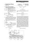
US007042438B2
(12)
(54)
United States Patent
(10) Patent N0.:
McRae et a].
(45) Date of Patent:
HAND MANIPULATED DATA APPARATUS
6,049,327 A *
FOR COMPUTERS AND VIDEO GAMES
6,097,369 A
6,154,199 A
(76) Inventors: Michael William McRae, 4025 Central
’
’
2004/0012564 A1*
Fremantle Ct., Roseville, CA (US)
( * ) Notice:
4/2000 Walker et a1. ............ .. 345/158
8/2000 Wambach
11/2000 Butler
0 13 e 3'
1/2004 Zngf et a1. ................ .. 345/158
OTHER PUBLICATIONS
?gségl’bj?lihljliaglllliit ilsclgzz’riigllno
’
May 9, 2006
113111? t 1
Ave., Fair Oaks, CA (US) 95628;
Adrian Gregory Albright’ 216
CA (Us) 95833’
US 7,042,438 B2
Ergo Touch, “Rocket Mouse”, OWner’s Manual, (1 page,
’
Subject to any disclaimer, the term of this
double sided).
Essential Reality, “The P5 Controller User Manual”, User
Manual’ (8 Pages, Smgle slded);
_ _
patent is extended or adjusted under 35
U_S_C_ 154(b) by 62 days
Essentlal Reahty, “The P5'Gam1ng Glove”, Descnptlon and
Spec1?cat1ons (2 pages, s1ngle slded).
*
(21) Appl. No.: 10/656,763
.
.
“ted by exammer
Primary ExamineriVijay Shankar
(22) Filed:
Sep. 6, 2003
(57)
(65)
US 2005/0052412 A1
(51)
(58)
Mar. 10, 2005
A computer or video game device for generating hand
manipulated data. The device consists of one or more
sensors that are mounted on the human hand. The sensors are
IIlt- Cl-
G09G 5/00
(52)
ABSTRACT
Prior Publication Data
(2006-01)
conveniently located for easy access and manipulation by
G09G 5/08
(2006-01)
US. Cl. .................... .. 345/156; 345/157; 345/158;
opposing ?ngers on the same hand that the sensors are
mounted on. This arrangement overcomes the limitations of
345/160
a tabletop computer mouse by not requiring a planar surface,
Field of Classi?cation Search ...... .. 345/156469;
341/20i22
and by not requiring the user to hold Onto the device
Additionally the sensors are located in such a Way that they
See application ?le for Complete Search history,
do not impede standard o?ice procedures such as using a
computer keyboard, Writing With a pen, holding a phone,
etcetera. The device can also be quickly and easily attached
(56)
References Cited
U.S. PATENT DOCUMENTS
4,414,537
4,988,981
5,444,462
5,488,362
5,489,922
5,581,484
A
A
A
A
A
A
5,638,092 A *
5,999,166 A *
11/1983
1/1991
8/1995
1/1996
2/1996
12/1996
Grimes
Zimmerman et 31.
Wambach
Ullman et a1.
Zloof
Prince
6/1997
12/1999
Eng et a1. ................. .. 345/158
Rangan .................... .. 345/157
or removed by the user. Various embodiments of the inven
tion include “Wired”, “Wireless”, multiple ?nger, universal
right or left-hand, universal ?nger or thumb application, and
universal side or top mounted sensors. Existing technologies
and manufacturing techniques are utilized to minimize cost.
Uses include personal computer, video game, and industrial
applications.
26 Claims, 14 Drawing Sheets
U.S. Patent
May 9, 2006
Sheet 1 0f 14
EEEEEEEEEEEEEEE ?g
Fig. 1B
US 7,042,438 B2
U.S. Patent
May 9, 2006
Sheet 2 0f 14
US 7,042,438 B2
U.S. Patent
May 9, 2006
Sheet 3 0f 14
US 7,042,438 B2
U.S. Patent
May 9, 2006
Sheet 4 0f 14
Fig. 3D
US 7,042,438 B2
U.S. Patent
May 9, 2006
Sheet 5 0f 14
US 7,042,438 B2
U.S. Patent
May 9, 2006
Sheet 6 0f 14
US 7,042,438 B2
U.S. Patent
May 9, 2006
Sheet 7 0f 14
US 7,042,438 B2
U.S. Patent
May 9, 2006
20
Sheet 8 0f 14
US 7,042,438 B2
U.S. Patent
May 9, 2006
Sheet 9 0f 14
US 7,042,438 B2
U.S. Patent
May 9, 2006
87
Sheet 10 0f 14
Fig. 8A
US 7,042,438 B2
U.S. Patent
May 9, 2006
Sheet 11 0f 14
US 7,042,438 B2
U.S. Patent
May 9, 2006
Sheet 12 0f 14
US 7,042,438 B2
166
164
U.S. Patent
May 9, 2006
Sheet 13 0f 14
US 7,042,438 B2
SENSOR
1
;
SENSOR TO COMPUTER
"
ELECTRONICS
—_>
11
COMPUTER
INTERFACE
A
172
Flg. 10
SENSOR
»
If“
COMPUTER
1
>
IV
a
,_
3
II
a
SENSOR
T
0
/
\ 17s
176
TRANSMITTER
ELECTRONICS
RECEIVER
INTERFACE
/
N —9
186
/
TO
COMPUTER
ELECTRONICS
172
INTERFACE
/
BATTERY
182
/ TRANSMITTER
%
RECEIVER
180
184
Fig. 11
U.S. Patent
May 9, 2006
Sheet 14 0f 14
US 7,042,438 B2
SENSOR
INPUT
r“
1
210 /
_>
.,
LEFT HAND
5
SENSOR
TO
"
——_e
"
;
L
%
TELEVISION
\
VIDEO GAME
192
TRANSMITTER
208 /
INTERFACE
ELECTRONICS
BOX
ELECTRONICS
188
RECEIVER
/
BATTERY
206 /
200
To
VIDEO GAME
TNTERFACE
/
TRANSMITTER
ELECTRONICS
196
RECEIVER
/
2 4
TRANSMITTER
0
198
202 \
BATTERY
190
\ 1n -——>
——'9 TRANSMITTER
RIGHTHAND
II
a
R A
SENSOR
INPUT
INTERFACE
ELECTRONICS
\
194
US 7,042,438 B2
1
2
HAND MANIPULATED DATA APPARATUS
FOR COMPUTERS AND VIDEO GAMES
hands, ?ngers, or Wrist. This is a particular issue When
moving the Wrist and ?ngers to type on a keyboard. Other
alternatives locate the sensors on parts of the hand that
subject them to accidental activation When holding a glass,
BACKGROUND
Writing With a pen, typing on a keyboard, or performing
other standard operations. Still other solutions separate the
1. Field of Invention
This invention relates to a human machine interface and,
more particularly, to a computer mouse type device for
entering data to a computer, video game, or similar machine.
mouse cursor movement function from the mouse “click”
function to such an extreme that once the desired cursor
position is obtained, the user must then reposition the hand
(and hence loose the desired cursor position) in order to
2. Description of Prior Art
It is knoWn in the ?eld of computers to utiliZe remote
computer interface devices that are hand-operated and used
activate the mouse “click” feature. Therefore the use of such
devices brings practical computer operation to a standstill.
in conjunction With the keyboard. A Well-knoWn computer
Here too a need exists for a mouse alternative that avoids
accidental sensor activation.
interface device is commonly knoWn as the computer
The third major problem in the industry is related to the
tactile and gripping ability of the human hand. As Will be
seen, many virtual reality glove type devices cover the
?nger-pads of the human hand. In other Words; devices that
mouse, Wherein the mouse is moved by hand over a planar
Work surface to move the cursor on the computer monitor.
The mouse also typically includes an electrical sWitch that
can be activated When the cursor is in a desired location in
order to cause an entry to the computer.
A problem With the mouse-type devices is that the mouse
is used in connection With a keyboard for data input. As a
20
and gripping surfaces of the ?ngertips. This is particularly
important When considering the registration “bumps” on the
result, the user must repeatedly move his or her hand
betWeen the keyboard and the computer mouse Work sur
“F”, “J”, and “5” keys of a computer keyboard. Therefore a
face. This hand movement required for the operation of the
computer mouse is both inef?cient and tiring to the user.
Therefore, a need exists for a mouse-type computer interface
device that does not require the user to move his or her hand
from the keyboard to a remote location in order to enter
need exists for a mouse alternative that leaves the ?nger
25
mouse-type data into the computer. Additionally this device
must not interfere With keyboard use, or the use of other
30
standard of?ce equipment.
Another problem With mouse-type devices is associated in
pads exposed When locating sensors in the ?ngertip area.
For example, US. Pat. No. 4,414,537 (Grimes) describes
a glove equipped With sensors for detecting sign-language
character type hand movements. This invention requires the
user to be ?uent in Single Hand Manual Alphabet for the
American Deaf. Although unique, this invention is expen
sive to manufacture With its many sensors. It should also be
noted that the “F”, “J”, and “5” keys on a computer keyboard
have special Braille type bumps that are sensed by the user’s
?ngertips to properly locate the hands and ?ngers on the
their use With laptop computers. The environment in Which
a laptop computer is used Will typically eliminate planar
surfaces as required by the typical computer mouse. Simi
larly, Wireless computer keyboards have been recently intro
locate sensors in the ?ngertip area also cover the ?nger-pads.
In doing so the user is left Without the tactile touch senses
35
keyboard. This invention violated that ability by covering
the ?ngertips. Therefore this invention Would make it dif
?cult for an operator to type. Additionally, it Would be very
duced to the market place. HoWever the user cannot fully
utiliZe the remote capabilities of these Wireless keyboards
dif?cult for the user to Write With a pen, or ansWer the phone
because the user must be near a planar surface in order to use
Without accidentally entering data. Lastly, this invention is
a tabletop mouse. Therefore, a need exists for a mouse-type 40 not Well suited to generate mouse-type cursor data.
computer interface device that does not require a planar
US. Pat. No. 4,988,981 (Zimmerman, et al) describes a
glove-type device used to manipulate virtual computer
surface to operate the mouse.
objects. The glove has several sensors and ultrasonic trans
mitters, and the computer monitor has several ultrasonic
Many alternatives exist for the computer mouse. It Will be
seen hoWever that most computer mouse alternatives suffer
from at lease one of three major problems in the industry.
The ?rst major problem in the industry relates to developing
receivers. The sensors are used to determine hand manipu
lation and the ultrasonic transmitters and receivers are used
neW hand-eye-coordination skills. For example, conven
tional computer mouse users have developed their hand
to determine relative hand position. This invention is Well
suited to determine virtual three-dimensional positioning,
45
and the manipulation of virtual computer objects. HoWever
eye-coordination skills to manipulate a mouse curser
through a single sensor (i.e. a track-ball, mouse-stick, optical
sensor, touch-pad, etcetera.). HoWever many computer
50
the many sensors and ultrasonic transmitters and receivers
make the device complicated and expensive. Additionally, as
mouse alternatives require multiple sensors for mouse cursor
compared to a conventional computer mouse, the device
control, and hence require multiple body parts to manipulate
those sensors. Moving these multiple body parts (hands,
requires excessive computer processing to manipulate the
?ngers, Wrist, etcetera) in a coordinated effort requires an
virtual objects. The invention also conceals the tips of the
55
The second major problem in the industry is related to
accidental sensor activation (accidental data entry). Most
user to operate the keyboard, Write With a pen, or ansWer the
phone Without accidentally entering data.
60
computer mouse alternatives are prone to accidental sensor
activation in one Way or another. This includes accidental
sensor activation caused by movements of the human hand,
and accidental sensor activation caused by touching or
holding things With the human hand. For example, virtual
reality type gloves detect hand motions, and Will move the
mouse cursor and enter commands by any movement of the
?ngers Whereby the user looses tactile senses as needed for
keyboard operation. Lastly, it Would be very dif?cult for the
entirely neW hand-eye-coordination skill set. Therefore a
need exists for a mouse alternative that does not require a
neW hand-eye-coordination skill set.
65
US. Pat. No. 5,489,922 (Zloof) utiliZes tWo concentric
rings placed on the index ?nger of each hand. The user spins
the ring on the right hand for vertical cursor movement, and
the ring on the left hand for horizontal cursor movement.
Further, each ring can be depressed to activate a sWitch so
as to simulate a typical mouse button. Although a novel
invention, this device requires the user to learn a Whole neW
set of hand-eye coordination skills. This is because the
horiZontal and vertical cursor movements originate from tWo
US 7,042,438 B2
4
3
different sensors, and hence requires tWo different and
independent body functions. Even more, the user must
combine these tWo neW hand-eye coordination skill sets in
requires the user to elevate his or her hand aWay from
order to have ?uid cursor movement. This in itself is yet
2. The invention is limited to a track-ball sensor for cursor
another hand-eye coordination skill that must be mastered
by the user. Additionally the cost and labor to manufacture
movement and does not consider other sensor types
a device that requires tWo sensors for a cursor movement is
etcetera.
the keyboard in order to avoid accidentally striking a
keyboard key.
such as a mouse-stick, optical sensor, scroll-Wheels,
3. The user must use tWo different ?ngers to execute the
more costly than a device that only requires one. The device
is also very mechanical in nature and is subject failure and
computer “drag-and-drop” command. This is because
one ?nger must be activating one of the palm-mounted
repeated maintenance. Further, this invention is intended for
buttons, While the thumb simultaneously activates the
use by persons Who have tWo hands. Therefore a disabled or
track-ball.
handicapped person having only one hand or missing ?ngers
Would have di?iculty in using these devices. Lastly, it Would
4. The palm-mounted buttons Will be accidentally acti
vated When performing standard tasks such as holding
be very dif?cult for the user to operate the keyboard or
a drinking glass, ansWering the phone, shaking hands,
ansWer the phone Without accidentally entering data.
U.S. Pat. No. 5,444,462 (Wambach), and Us. Pat. No.
6,097,369 (Wambach) both describe a glove type device that
pushing against the armrests of a chair While standing
has various sensors mounted on it. Vertical cursor movement
is obtained by moving the index ?nger up and doWn, and
20
horizontal cursor movement is obtained by rotating the Wrist
left or right. Although novel inventions, these devices
require the user to learn a Whole neW set of hand-eye
coordination skills. This is because the horiZontal and ver
tical cursor movements originate from tWo different sensors,
the thumb or other ?ngers of the hand.
7. The glove type device cannot be quickly and conve
niently attached or removed. This makes it more dif
?cult to Wash hands, shake hands, use the bathroom, or
25
and hence requires the user to manipulate tWo different
body-parts. This requires the user to learn and develop tWo
operators Were using the same device.
30
device With sensors mounted on the ?ngertips. This device
movement is more costly than a device that only requires
surface such as a tabletop. The manner in Which each sensor
35
fashion also presents a problem, as the glove cannot be
conveniently attached or removed. This makes it more
dif?cult to use the bathroom, Wash hands, etcetera. Finally,
Although a novel invention for keyboard entry, this device
40
mounted device used to acquire ?nger manipulation data.
easily attached or removed.
45
ring transmits a signal that is received by multiple receivers
imbedded in the computer keyboard. The receivers deter
mine cursor movement as the ring is moved up, doWn, and
50
user to Wear a sensor cap on each ?ngertip. This cap blocks
across the keyboard. A special button is mounted adjacent to
the keyboard space bar to accommodate the mouse “click”
the sensory tactile touch as needed by the user for keyboard
operation. Additionally the sensors used in the device are
button feature. Although an interesting invention, this device
requires specialiZed computer keyboards With multiple
expensive, bulky, cannot be easily attached or removed, and
are not Well suited for mouse equivalent data.
U.S. Pat. No. 5,638,092 (Eng, et al), describes a ring type
device that is mounted on the ?nger of a computer user. The
The data obtained from this device is used to analyZe human
?nger movements in order to better understand and operate
robot hands. Although an interesting invention, this device
interferes With computer keyboard entry by requiring the
is not Well suited to generate mouse equivalent data. The
many sensors are also expensive and Would be accidentally
activated When using the computer mouse, ansWering the
phone, etcetera. Lastly, this glove type device cannot be
does not Wish to generate mouse commands.
U.S. Pat. No. 6,526,669 B2 (Nagata), describes a hand
reacts during each virtual keystroke alloWs the computer to
predict What key the user intends to depress. This alloWs the
user to incorporate any ?at surface as a virtual keyboard.
it Would be nearly impossible to use the computer keyboard
or perform other standard of?ce functions Without acciden
tally activating the sensors on these devices. Therefore these
units must be disabled or entirely removed When the user
U.S. Pat. No. 5,581,484 (Prince), describes a glove type
is attached to a computer Which interprets relative ?nger
positions as the ?ngers are moved and pressed against a ?at
to manufacture a device that requires tWo sensors for cursor
one sensor. Having the sensors mounted in a glove-type
perform other hygiene functions.
8. The invention Would require periodic sterilizing and
cleaning similar to that of an article of clothing. This
Would be especially necessary in the event that multiple
neW, different, and independent hand-eye coordination
skills. Even more, the user must combine these tWo skills
together in order to have ?uid cursor movement. This in
itself is yet another neW hand-eye coordination skill that
must be mastered by the user. Additionally the cost and labor
up, etcetera.
5. The invention fails to utiliZe a convenient means to turn
the unit on or o?‘.
6. The invention does not consider mounting sensors on
receivers. These keyboards Would be expensive and Would
55
make it dif?cult to use the ring device With existing com
U.S. Pat. No. 6,154,199 (Butler), describes a glove-type
puters Without also replacing the keyboard. This device also
device that has a track-ball mounted on the side of the index
requires the user to remove the ring-hand from the keyboard
position, and then move it according to desired cursor
direction. Then the user must reposition the ring-hand on the
?nger, and buttons mounted on the palm of the hand. Cursor
movement is obtained by manipulating the track-ball With
the thumb, and button activation by pushing the palm
60
mounted buttons With the ?ngers. Although an interesting
user to abandon their keyboard hand position just to try and
?nd it again. This device has also divided the hardWare and
operator means of generating mouse equivalent data. Cursor
invention, this device has several limitations as folloWs:
1. The user must make a conscience effort to not acci
dentally strike a computer keyboard key While sWeep
ing the ?ngers around to press the palm-mounted
buttons. In other Words, When transitioning from key
board entry to palm-button activation, the invention
keyboard. This tedious back and forth procedure requires the
position is generated by moving the ring, but the mouse
65
“click” button is placed on the keyboard. This prevents the
user from generating mouse equivalent data Within the
con?nes of a single hand. This leads to the ultimate short
US 7,042,438 B2
6
5
coming of the device. This shortcoming is due to the fact that
g) The device Would require periodic sterilizing and
once the user locates the ring for desired cursor position; the
user must then move the hand (ring) back to the keyboard
“click” button in order to activate the mouse command. In
doing so, the user looses the desired cursor position. There
fore the user is unable to simultaneously position the curser
and click the keyboard mouse button With a single hand.
cleaning similar to that of an article of clothing. This
Would be especially necessary in the event that multiple
operators Were sharing the same device.
h) The device requires the user to rotate the Wrist between
@180 degrees. This is a di?icult task to perform and
could eventually lead to a repetitive-stress injury.
i) The device fails to utiliZe Wireless communications
Hence the device is unable to function as a computer mouse
replacement. Additionally, the user’s hand must never leave
the proximity of the receivers in the computer keyboard as
Whereby the user Would not be tethered to the com
puter.
this Would render the device unusable. Therefore the user is
alWays tethered to the computer keyboard. Lastly, the cursor
Will be moving across the screen in an uncontrolled manner
as the user types on the keyboard. This Will be an obvious
15
annoyance the user.
Pub. No.: US 2004/0012564 A1 (Zngf, et al), describes a
virtual reality glove type device that has a tilt sensor
mounted on the back of the hand, and bending sensors
mounted on each ?nger of the glove. As the user rotates their
Wrist between @180 degrees, the tilt sensor changes the
corresponding roll-angle of the on-screen cursor. Once the
desired angle of travel is obtained, the user then moves the
20
25
the cursor from right-to-left along the line of travel. Once the
little ?nger. Although unique, this device has several limi
30
manner.
dimensional positioning device that utilizes optical electron
hand-eye-coordination skill set. This is due to the fact
that cursor movement is obtained from three different
sensors instead of just one. Hence, three different body
35
ics. The device consists of a tabletop enclosure that has a
light source and a light detector. The user Wears a ring type
re?ector that positions a small mirror on the underside of the
hand. Light is then shone upWard from the tabletop unit to
move the cursor instead of just one body element. This
the mirrored re?ector under the hand. The user then moves
puts the invention at a disadvantage When compared to
the hand (re?ector) over the device to re?ect the light source
devices that obtain cursor movement from a single
sensor.
40
to speci?c locations on the light detector. Re?ecting light on
different areas of the light detector results in a corresponding
tWo-dimensional mapping, or cursor positioning, on the
function such as typing on the keyboard. This is due to
the fact that as the user types (or performs other
functions), the mouse cursor Will be moving across the
computer screen. Third-dimensional command data (if
needed) is obtained by raising the re?ector and hence
loWering the intensity of re?ected light on the light detector.
computer screen in an uncontrolled manner. Adding
“mouse-click” activation from the
fact that the unit fails to include a mouse “click” button.
Additionally, the device cannot be used When performing
U.S. Pat. No. 5,999,166 (Rangan), describes a three
a) The device requires the user to learn a Whole neW
simultaneous
movements. Hand gestures are thereby converted to com
to the fact that as the user types, the mouse cursor Will be
moving across the computer screen in an uncontrolled
mouse “click” button by bending either the middle, ring, or
b) The device cannot be used When performing any other
that is placed on the backside of the hand. This ?exible
circuit board has a special characteristic in that it can detect
?exation. In doing so the device can detect ?nger and thumb
other functions such as typing on the keyboard. This is due
cursor is at the desired location, the user then activates the
elements (Wrist, thumb, index-?nger) are required to
reality glove type device that is used to control computer
animations. The glove contains a hand shaped circuit board
puter commands for controlling computer-based animations.
from left-to-right along the angular line of travel. LikeWise
tations as folloWs:
capped persons Who are missing one or more ?ngers.
U.S. Pat. No. 6,049,327 (Walker, et al), describes a virtual
Although a unique invention, the device is not Well suited
for mouse equivalent computer commands. This is due to the
thumb toWard the index ?nger in order to move the cursor
the user moves the index ?nger toWard the thumb to move
j) The device requires the use of all the ?ngers of the
human hand, and therefore cannot be used by handi
45
middle, ring, and little ?nger Will bring complete
Once the cursor is in the desired location, the user then
depresses one of the buttons located on the front (?nger) side
of the tabletop unit. Although an interesting invention, the
mayhem to the computer environment.
device Would be difficult to use in place of a computer
mouse. This shortcoming is due to the fact that once the user
c) The cost and labor to manufacture a device that requires
three sensors for cursor movement is more costly than
50 locates the re?ector ring for desired cursor position; the user
a device that only requires one sensor.
must then move the hand (ring) back to a location Where the
d) The device is not designed for universal right or left
hand operation. This is due to the fact that When the
device is moved from the right hand to the left, all of
the sensors Will function in the opposite direction. This
Would be a particular problem for ambidextrous users.
buttons can be depressed. In doing so, the user looses the
desired cursor position. This problem is further magni?ed
55
This problem Would require expensive bi-directional
sensors, and/or a separate device program for left
handed users. Additionally, using the device on the left
hand places the sensors on the Wrong side of the glove.
This may interfere With other Work functions.
60
e) The device fails to utiliZe a convenient means to turn
The Rocket Mouse (by ErgoTouch) is another computer
the unit on or off.
mouse type device. This unit has a track-ball and mouse
f) The glove type device cannot be quickly and conve
niently attached or removed. This makes it more dif
?cult to Wash hands, shake hands, use the bathroom, or
perform other hygiene functions.
When the re?ective ring is Worn on the same ?nger that Will
be moving doWnWard to depress the mouse button. There
fore the user is unable to simultaneously position the curser
and click the mouse button. Hence the device does not
function as a computer mouse replacement. Additionally, the
user’s hand must never leave the proximity of the tabletop
unit, as this Would render the device unusable. Therefore the
user is alWays tethered to the computer desk.
buttons mounted in a hand-held package. The user holds the
65
device betWeen the index ?nger and the thumb. Activation
of the track-ball and mouse buttons is by Way of the thumb.
Although an exiting invention, this device requires the user
US 7,042,438 B2
7
8
to hold onto it. Therefore the unit must be put doWn in order
to use the keyboard, answer the phone, Write With a pen,
glove. Therefore, this device fails to take advantage of more
etceteras.
Another application for data entry devices is for video and
computer games. These devices, called “controllers”, are
Well knoWn and typically involves some kind of hand held
joystick With multiple buttons, ray guns, race car steering
5
sophisticated sensors such as a track-ball, mouse-stick,
scroll-Wheel, or even a hand mounted mini joystick. Also,
the device completely covers the hand and therefore blocks
the tactile senses. Further, the device can be easily short
circuited as the electrical contacts of the device are exposed.
This Would preclude drinking from a metal cup, or resting
the hand on a metal object. Lastly, the glove cannot be
quickly and easily attached or removed from the hand.
Wheels, and so on. Like a computer mouse, most of these
devices require the user to hold onto them. Therefore the
user must put the device doWn in order to use a second data
OBJECTS AND ADVANTAGES
input device, ansWer the phone, etcetera. Additionally,
devices such as a steering Wheel and foot pedals are sta
tionary and do not provide users the freedom to move about.
Therefore, a need exists for a portable device that does not
require the user to hold onto it, and one Which doesn’t
interfere With other activities such as using a second data
5
input device or ansWering the phone. Further, video and
Accordingly, several objects and advantages of our hand
manipulated data apparatus are:
a) To provide a hand manipulated data apparatus that does
not require a planar surface.
b) To provide a hand manipulated data apparatus that does
computer game operators enjoy the feeling of becoming
not require the user to remove their hand from the
engrossed in the game by having a data input device attached
keyboard area.
to their body in some manner. Therefore a need exists for a 20
device that can be easily attached and removed from the
user’s body.
Virtual reality has also recently gained much interest in
the video and computer game industry. HoWever, these
devices typically rely on expensive transmitters and receiv
keyboard.
25
ers to obtain relative positioning. They are also typically
arranged in a glove type fashion that blocks the users tactile
senses, and makes attachment and removal of the device
more cumbersome. These devices also make it difficult to
perform other tasks such as ansWering the phone or using the
computer keyboard Without accidentally entering a com
user to activate more than one sensor at a time for
cursor movement, and by not requiring the user to learn
35
gun. This is accomplished by mounting infrared transmitters
on the gun, and infrared receivers on the video or computer
display. The receivers determine the relative signal delay
interface. HoWever it requires the user to hold onto the
pointing device. Therefore the user must put the device
doWn in order to perform other tasks such as ansWering the
40
45
phone, drinking from a glass, using a second data input
device, etcetera. Also, the transmitters must be spaced a
signi?cant distance from each other in order to obtain proper
resolution for position and orientation. This makes for a
bulky and aWkWard user interface. These transmitters and
receivers are also expensive and add to the complexity of the
50
device. Additionally, video and computer game operators
55
ing more than a series of electrical contacts mounted on a
number of additional circuit components.
j) To provide a hand manipulated data apparatus that
appeals to handicapped persons.
k) To provide a hand manipulated data apparatus that
appeals to persons suffering from carpal-tunnel-syn
drome.
1) To provide a hand manipulated data apparatus that can
places of the hand, or hands.
m) To provide a hand manipulated data apparatus that is
suitable for use With a plurality of sensor types,
con?nes of the hand that the sensors are mounted on.
60
as up-doWn, left-right, and Weapons ?re. Joystick type
functions are accomplished by moving the Wrist in various
directions, and push-button type functions are obtained by
interesting transformation of a joystick, this device is noth
simple and inexpensive to manufacture by utiliZing
existing technologies, and by introducing the feWest
n) To provide a hand manipulated data apparatus that can
have all of the sensors manipulated solely Within the
glove represent corresponding joystick type functions such
contacting one or more ?ngers to the thumb. Although an
entirely neW hand-eye coordination skills.
g) To provide a hand manipulated computer mouse that is
suitable for computer use, video games, virtual reality,
and industrial applications.
h) To provide a hand manipulated data apparatus that can
easily be used to perform the “drag-and-drop” com
puter function.
i) To provide a hand manipulated data apparatus that is
have a plurality of sensors mounted on numerous
enjoy the feeling of becoming engrossed in the game by
having a data input device attached to their body in some
fashion. This device fails to do so. Lastly, the device is not
Well suited to generate computer mouse equivalent data,
should it be used in that capacity.
U.S. Pat. No. 5,488,362 (Ullman, et al), describes a glove
type device that is used in place of a hand held joystick. The
connection of different exposed electrical contacts on the
handling other objects.
f) To provide a hand manipulated data apparatus that is
user friendly and easy to operate by not requiring the
One such example is U.S. Pat. No. 6,540,607 B2 (Mokris,
betWeen the various transmitters to determine position and
orientation. This device is Well suited for video game
applications that require a point and shoot type of user
d) To provide a hand-manipulated data apparatus that is
not accidentally activated by performing standard
office procedures such as ansWering the phone, Writing,
or holding a drinking glass.
e) To provide a hand manipulated data apparatus that does
not block the tactile senses of the ?nger pads, Whereby
the user is not impaired When using the keyboard or
30
mand. Lastly, these devices are not Well suited for other uses
such as generating mouse equivalent data
et al), describes a video or computer game device that
detects the location and orientation of a pointing device or
c) To provide a hand manipulated data apparatus that is
not accidentally activated When using the computer
65
0) To provide a hand manipulated data apparatus that can
be quickly and easily attached to the user’s hand, or
removed from the user’s hand.
p) To provide a hand manipulated data apparatus that can
be quickly and easily stored on the user’s body.
q) To provide a hand-manipulated data apparatus With
features that compare to today’s most sophisticated
desktop computer mice.
US 7,042,438 B2
10
r) To provide a hand manipulated data apparatus that
compares to today’s most sophisticated video game
enclosure as the sensors. For a “Wired” mouse, the electron
ics enclosure typically resides next to the computer. For a
“Wireless” mouse, the electronics interface (transmitter) may
be packaged With the sensors, or in a separate enclosure on
controllers (user input devices).
s) To provide a hand manipulated data apparatus that can
either have a “Wired” or “Wireless” connection to the
the user’s Wrist, or other part of the body. The “Wireless”
computer and or video game.
receiver Would typically reside next to the computer, or
could even be built into the computer.
Further objects and advantages Will become apparent from
a consideration of the drawings and ensuing description.
removed from the users hand. In one embodiment the
SUMMARY
mounted Wireless transmitter enclosure, Where they can also
The foregoing and other objects of the invention are
attained in the transformation of a tabletop mouse (or video
provides the user With the necessary freedom to perform
game controller), into a device that resides on the human
hands, shaking hands, eating, and so on.
hand(s). This is accomplished by placing sensors (buttons,
sWitches, scroll-Wheels, track-ball, joystick, etc.) on the
a mouse that resides on the human hand is very bene?cial.
When necessary, the ?nger-mounted unit can be easily
?nger-mounted sensors are easily retracted to the Wrist
be quickly re-deployed back onto the user’s ?nger(s). This
personal hygiene tasks such as using the bathroom, Washing
This transformation of a conventional tabletop mouse, to
human hand. These sensors are located on the human hand
so as not to impede ordinary hand functions or touch-senses,
but yet to alloW the sensors to be activated by other parts of
the hand such as the thumb and ?ngers. Having the sensors
20
the sensors are located so that the sensors are not acciden
activated Within the con?nes of the human hand eliminates
the need for a planar surface that an ordinary tabletop mouse
requires. Further, it eliminates the need for the user to
remove their hand from the keyboard area in order to enter
tally activated When ansWering the phone, Writing on paper,
typing on the computer, holding a drinking glass, etcetera. In
addition, conventional computer mouse sensors are utiliZed
25
mouse-type data. It is also understood that contemporary
computer mice provide the user With selectable options
When con?guring the computer mouse. For example the user
Whereby the user is not required to learn extensively neW
hand-eye coordination skills. All of the functions that are
typical of a conventional tabletop mouse are easily obtained
through this invention, but the limitations of a tabletop
could con?gure the mouse for a left-handed person in Which
the “left-mouse-button” Would be con?gured as the right,
and vice-versa. This invention also retains these types of
One can easily see that a planar surface is not required for
cursor movement; the user’s ?nger pads are not covered and
therefore the user’s keyboard touch-senses are retained; and
mouse are eliminated.
30
user con?guration capabilities.
In a typical embodiment, a dual function mouse-stick
sensor is placed on the thumb side of the index ?nger. (Note
Although the above discussion focused on the invention
being mounted on a single hand, it could just as easily be
mounted on both hands, other ?ngers or thumb, multiple
?ngers, or even other parts of the body. Mounting the
invention on other parts of the body may be especially
that a mouse-stick sensor is the type of mouse sensor 35 applicable for disabled or handicapped persons. It can also
commonly employed in the center of laptop computer key
be seen that the invention can easily be used for computer
boards. It looks like a small button and is gently pushed in
and video game applications.
various directions resulting in mouse cursor movement on
Finally, the loW cost and ease of manufacture of the
the computer screen. The most recent development in mouse
depressing the mouse stick. This Will be referred to as a dual
present invention is obtained by utiliZing existing technolo
gies, and by introducing the feWest number of additional
circuit components. Further objects and advantages Will
function mouse stick.) The user’s thumb then has easy
become apparent from a consideration of the ensuing
access to this sensor and can activate this sensor by gently
description and draWings.
stick design employs a built-in button that is activated by
40
pushing the mouse-stick in the direction of desired cursor
movement. Additionally the user can utiliZe the dual func
tion of the mouse stick by pressing doWnWard on the mouse
FIGS. 1A & 1B are a “Wired” illustration of a basic form
stick and activating the built in click-button. This built in
button Would typically be con?gured by the user to be
of the invention utiliZing a single mouse-stick, and a single
button.
equivalent to the left-click button of a tabletop mouse. This
dual function mouse-stick then permits ordinary cursor
50
FIGS. 2A & 2B are a “Wired” illustration of the invention
utiliZing a single mouse-stick, a single button, a horizontal
navigation scroll Wheel, and a vertical navigation scroll
Wheel.
movement, text highlighting, “drag-and-drop”, “double
click” and so forth; all With the users thumb. Adjacent to the
mouse-stick sensor is a separate click-button. This button is
also easily accessible by the thumb and serves the purpose
of the “right-click” mouse button of a typical tabletop
DRAWING FIGURES
45
FIGS. 3A & 3B are a “Wireless” illustration of the
55
invention utiliZing a ?rst mouse-stick, a second mouse-stick
mouse. Also near this ?rst mouse-stick is a second mouse
in place of scroll Wheels, a single button, and retractable
stick. This second mouse-stick Would be used in place of a
sensors.
scroll-Wheel as employed on a conventional tabletop com
puter mouse. (Note, a scroll-Wheel is the type of sensor that
FIGS. 3C & 3D are a “Wireless” illustration of the
invention utiliZing a ?rst mouse-stick, a second mouse-stick
is used on a conventional tabletop mouse to scroll Within 60 in place of scroll Wheels, a single button, and retractable
sensors of Which are shoWn retracted.
softWare applications.) The thumb is used to activate this
FIGS. 4A & 4B are a “Wireless” illustration of the
second mouse-stick to generate mouse equivalent “scroll
that is easily accessible by the thumb. This Would alloW the
invention utiliZing a ?rst mouse-stick, a second mouse-stick
mounted on the dorsal ?ngertip, tWo buttons, and retractable
user to easily turn the unit on or off. The electronics interface 65
sensors.
Wheel” data. The invention may also have an on/olf button
required for the invention may be “Wired” or “Wireless”, and
FIGS. 4C & 4D are a “Wireless” illustration of the
may reside inside a separate enclosure, or reside in the same
invention utiliZing a ?rst mouse-stick, a second mouse-stick