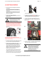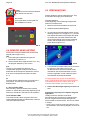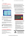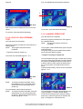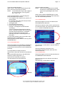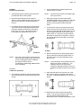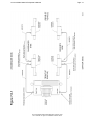
1
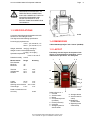
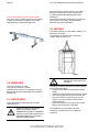
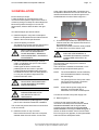
ACCU 2200 CCD
COMPUTER WHEEL ALIGNER FOR CARS AND LIGHT TRUCKS
WITH CCD SENSORS
INSTALLATION AND OPERATION INSTRUCTIONS
MAINTENANCE INSTRUCTIONS
Page 2
Accu-turn Model 2200 CCD Operator’s Manual
Accu-turn Model 2200 CCD Release #01 February 2001
Accu reserves the right of modification without notice.
Accu-turn Model 2200 CCD Operator’s Manual
Page
Copyright statement
This manual and the materials contained within are the property of the Manufacturer.
The manual, or any section, page, drawing, or screen capture, may not be
reproduced by any means without the written consent of the Manufacturer.
The information and specifications in this manual are based on the latest information
available at the time of publication. The product manufacturer reserves the right to
change the specifications at any time without notice.
Accu-turn Model 2200 CCD Release #01 February 2001
Accu reserves the right of modification without notice.
3
Page 4
Accu-turn Model 2200 CCD Operator’s Manual
Accu-turn Model 2200 CCD Release #01 February 2001
Accu reserves the right of modification without notice.
Page
Accu-turn Model 2200 CCD Operator’s Manual
TABLE OF CONTENTS
TABLE OF CONTENTS
1.0 INTRODUCTION
5
7
1.1 FIELD OF APPLICATION
1.2 SAFETY
1.3 SPECIFICATIONS
1.4 DIMENSIONS
7
7
9
9
1.5 LAYOUT
1.6 STANDARD ACCESSOIRIES
1.7 OPTIONS
9
10
11
2.0 HANDLING
12
2.1 UNPACKING
2.2 MOVING
12
12
3.0 INSTALLATION
4.0 GETTING STARTED
13
15
4.1 SHUTTING DOWN
4.2 NAVIGATION
4.3 SCREEN LAYOUT
4.4 SENSOR HEAD KEYPAD
4.5 PREPARATIONS
16
16
16
18
18
5.0 MAIN MENU
19
5.1 WORKING PROGRAMS
5.1.1 CAR SPECIFICATION DATA BANK
5.1.2 CUSTOMER INFORMATION
5.1.3 RUN-OUT COMPENSATION
5.1.4 CASTER/SAI MEASUREMENT
5.1.5 INITIAL MEASUREMENTS
5.1.6 ADJUSTMENT REAR AXLE
5.1.7 FRONT LEFT ADJUSTMENT
5.1.8 FRONT RIGHT ADJUSTMENT
5.1.9 FRONT TOE
5.1.10 CASTER CONTROL (RECHECK)
5.1.11 TOE OUT ON TURNS
5.1.12 LOCK TO LOCK STEERING TEST
5.1.13 4-WHEEL STEER TEST
5.1.14 FINAL MEASUREMENTS
5.1.15 Intentionally empty
5.2 UTILITY PROGRAMS
5.2.1 PERSONAL DATA
5.2.2 CUSTOMER DATA
5.2.3 UPDATE
5.2.4 USER CALIBRATION
5.2.5 INTERNET LINK
5.3 SYSTEM CONFIGURATION
5.3.1 Explanation of fields
5.4 SERVICE PROGRAMS
19
20
22
22
23
24
24
25
25
26
26
27
28
28
29
30
30
30
32
34
34
37
37
37
39
6.0 MAINTENANCE
39
6.1 CALIBRATION FRAME
40
7.0 TROUBLE SHOOTING
40
7.1 ERROR MESSAGES
40
8.0 STORAGE CONDITIONS
9.0 DISPOSING OF THE UNIT
40
42
Accu-turn Model 2200 CCD Release #01 February 2001
Accu reserves the right of modification without notice.
5
Page 6
Accu-turn Model 2200 CCD Operator’s Manual
Accu-turn Model 2200 CCD Release #01 February 2001
Accu reserves the right of modification without notice.
Page
Accu-turn Model 2200 CCD Operator’s Manual
1.0 INTRODUCTION
Congratulations on purchasing the ACCU
2200CCD computer wheel aligner.
This wheel aligner is designed for ease of
operation, accuracy, reliability and speed.
With a minimum of maintenance and care
your computer wheel aligner will provide
many years of trouble-free operation.
Instructions on the use, maintenance and
operational requirements of the machine are
covered in this manual.
The aligner requires a very specific set of
computer hardware components. All these
components are integrated for optimum speed
and functionality of the software. Substitution
of these items, or the addition of any other
computer components to the aligner, could
compromise proper operation and is not
recommended. Consult Technical Support
prior to performing any changes to the
hardware configuration.
The aligner’s program is Windows based. DO
NOT manipulate, change or copy any files
onto the system configuration unless qualified
to do so. The aligner may not operate properly
if unauthorised changes have been made.
STORE THIS MANUAL IN A SAFE
PLACE FOR FUTURE REFERENCE.
READ THIS MANUAL THOROUGHLY
BEFORE USING THE MACHINE.
1.1 FIELD OF APPLICATION
The computer wheel aligner model ACCU
2200CCD is intended to be used as a device to
measure the alignment angles of passenger
cars and light trucks.
This device must be used only for the
application for which it is specifically
designed.
Any other use shall be considered as improper
and thus unreasonable.
The manufacturer shall not be considered
liable for possible damages caused by
improper, incorrect or unreasonable use.
7
This product is intended for use by suitably
qualified, properly trained personnel, familiar
with health and safety procedures and
practices relating to garage equipment.
There are many variations in the procedures,
techniques, tools and parts for servicing
vehicles, as well as in the skill of the
individual doing the work. Because of the vast
number of vehicle applications and potential
uses of the product, the manufacturer cannot
possibly anticipate or provide advice or safety
messages to cover every situation. The
operator is responsible for his knowledge of
the maintenance procedures relating to the
vehicle being worked on. It is essential that
proper service methods be used at all times
and that work is carried out in an appropriate
and acceptable manner that does not
endanger your safety, the safety of others in
the work area, the equipment or the vehicle
being serviced.
Prior to using this equipment the operator
should have a thorough understanding of the
vehicle systems being serviced. Operators
should also have a thorough knowledge of the
operation and safety features of racks or
vehicle lifts used and have access to the
proper hand and power tools required.
Before using this product always refer to and
follow the safety messages and service
procedures provided by the manufacturer of
any other equipment being used or of the
vehicle being serviced.
1.2 SAFETY
This equipment is designed and manufactured
to stringent safety requirements. In order to
maintain the equipment in a safe condition
and ensure its safe operation, the operating
instructions MUST be followed and warnings
and cautions strictly observed.
ALWAYS ensure this equipment is only operated
by personnel trained in its correct use and familiar
with its operation as outlined in the Operator’s
Manual. Operators should be familiar with all the
safety features of the machine and must at all
times operate the machine only for its intended
purpose.
ALWAYS ensure that the main supply is connected
to an outlet with protective earth grounding.
Accu-turn Model 2200 CCD Release #01 February 2001
Accu reserves the right of modification without notice.
Page 8
Accu-turn Model 2200 CCD Operator’s Manual
ALWAYS route the power cord away from moving
parts and in such a manner that it will not be
tripped over, pulled or damaged.
ALWAYS ensure that if a power extension cord is
used that it has a current rating equivalent to that of
the power cord supplied and has a protective earth
ground circuit. We recommend that where
possible the use of such a power extension cord is
avoided.
ALWAYS ensure that replacement fuses or circuit
breakers are of the correct rating and type as
specified.
ALWAYS ensure safety clothing or eye protection
is used where specified.
ALWAYS ensure all access panels have been
replaced after any service work has been carried
out on the unit.
ALWAYS ensure the equipment is disconnected
from its power source when not in use.
ALWAYS ensure the area surrounding the
equipment is restricted to qualified personnel only.
stresses
•
has been subjected to prolonged storage
under unfavourable conditions
•
has been recently exposed to rain,
excessive moisture or had liquids spilt on it.
NEVER connect or attempt to operate the unit at
voltages/frequencies other than specified on the
product label.
NEVER operate the unit in an area where there are
exposed flammable liquids or fumes.
NEVER operate the unit on wet surfaces or
otherwise expose it to moisture or rain. Our
products are generally intended for indoor use only
unless otherwise specified.
NEVER short circuit or bypass safety devices.
NEVER remove access panels or covers without
first of all ensuring that power to the unit has been
removed.
NEVER wear a necktie, scarf or loose clothing near
a unit which may have exposed rotating parts.
ALWAYS ensure that where vehicle lifts or jacks
are used the manufacturers safety instructions are
strictly followed.
NEVER attempt to lift the unit without adopting the
correct lifting procedures.
ALWAYS ensure vehicles are properly secured on
vehicle lifts before use.
NEVER operate the equipment where there is a risk
of exposure to flammable vapours.
•
Leave vehicles with automatic transmission
in park, or with manual transmission in
gear unless equipment operation steps
specifically require otherwise.
•
Apply the parking brake.
•
Use wheel chocks when a vehicle is
positioned on a vehicle lift.
CAUTION
ANY MISUSE OR MODIFICATION OF
THIS DEVICE OR OF ITS PARTS OR
COMPONENTS NOT PREVIOUSLY
AUTHORIZED BY THE
MANUFACTURER RELIEVES THE
MANUFACTURER OF ANY
DAMAGE CONSEQUENT ON
OR RELATED TO THE ABOVE
MENTIONED MISUSES OR
MODIFICATIONS.
NEVER wear wrist watches, rings or other jewelry
when working on a vehicle as they may catch in
moving parts or cause an electrical short circuit.
CAUTION
THIS EQUIPMENT IS DESIGNED TO
RECEIVE ORIGINAL SPARE PARTS
AND ACCESSORIES ONLY.
NEVER touch hot exhaust systems, manifolds, or
engine parts which may cause burns.
NEVER operate the unit or connect power to it
when the equipment:
•
shows signs of visible damage
•
has been subjected to severe transportation
WARNING
REMOVING OR BYPASSING
SAFETY DEVICES OR WARNING
LABELS OF THE MACHINE IS A
VIOLATION OF THE SAFETY
REGULATIONS.
Accu-turn Model 2200 CCD Release #01 February 2001
Accu reserves the right of modification without notice.
Page
Accu-turn Model 2200 CCD Operator’s Manual
WARNING
9
THE INSTALLATION AS WELL AS
THE ELECTRICAL CONNECTION
SHALL BE CARRIED OUT ONLY BY
QUALIFIED PERSONNEL AND
WITHIN THE SCOPE OF THE
INSTRUCTIONS PROVIDED FOR IN
THIS MANUAL.
1.3 SPECIFICATIONS
1.4-1
Computer wheel alignment apparatus with CCD
sensors for cars and light trucks.
The aligner has the following specification:
Power supply requirements:
110 V~, 1ph, 50-60 Hz, 1 A
230 V~, 1ph, 50-60 Hz, 1 A
Weight, standard 155 [kg] / 340 [lbs.]
Weight of sensor and standard clamp
7.5 [kg] / 16.45 [lbs.]
Operation temperature
0-50 °C / 32-122 °F
Relative humidity 0-90 %
Measurement
Rim diameter
Minimum
Maximum
Range
10"
20"
Total toe
Individual toe
Camber
±9.0°
±4.5°
±8.0°
1450x1050x600 [mm]/ 57”x41.3”x23.5” (HxWxD)
1.5 LAYOUT
Familiarity with the layout of the parts of the
aligner is required before installation, use or
maintenance operations are attempted.
1
Accuracy
±2.0’
±1.0’
±3.0’
Caster
±21.0°
±7.0’
Setback
± 3.0°
±1.0’
Steering axis inclination ±21.0°±6.0’
Thrust angle
± 5.0°
±1.0’
Read-out resolution 0.01°
Accuracy
1.4 DIMENSIONS
2
3 4
11
10
5
9
6
7
1.5-1
±0.05°
Refer to figure 1.5-1. 8
1. Console
2. SVGA monitor
3. Mouse
4. Computer keyboard
(in drawer)
5. Printer (in drawer)
6. Computer
7. Storage system for
sensor heads
Accu-turn Model 2200 CCD Release #01 February 2001
Accu reserves the right of modification without notice.
8. Storage cabinet
9. Sensor Head on
clamp
10.Storage for
sensor heads
11.Tightening knob
wheel clamp
Page 10
Accu-turn Model 2200 CCD Operator’s Manual
1
2
3
1.6 STANDARD ACCESSOIRIES
The monitor has its own power switch, which
should be left on all the times, plus controls to
adjust settings such as horizontal, vertical,
brightness, etc.... Refer to monitor manual supplied
with each alignner. NOTE: monitor may differ from
the one shown.
1.5-2
#22-00102 17” SVGA multimedia monitor
Refer to figure 1.5-2.
1. On/off switch (PC).
2. Floppy disk drive.
3. CD ROM drive.
1
2
1.5-3
Refer to figure 1.5-3.
1. Main switch
2. Ventilation grille
3
2
#22-00103 Inkjet Color printer
NOTE: printer may differ from the one shown.
Refer to printer manual for controls, switches, and
maintenance of printer.
8
1
7
9
4
5
6
1.5-4
Refer to figure 1.5-4.
1. Sensor head keypad
2. Head locking knob
3. Head quick release button
4. On/off head switch
5. Fuse holder.
6. Electronic turntable cable receptacle
7. Signal cable receptacle
8. Track toe CCD module
9. Cross toe CCD module
#22-00111 Steering lock
Accu-turn Model 2200 CCD Release #01 February 2001
Accu reserves the right of modification without notice.
Page 11
Accu-turn Model 2200 CCD Operator’s Manual
#22-00110 Brake pedal depressor
1.7 OPTIONS
#22-00112 Mechanical painted mild steel turntable
set
Capacity: 4000lbs per set
#22-00113 Mechanical stainless steel turntable set
Capacity: 4000lbs per set
#22-00104 Electronic turntable set
Capacity: 1760lbs
#22-00109 Universal Quick Clamp
Centers on alloy wheels, run-out compensation not
necessary
# 4024662 Pro-Clamp kit
(Audi/Porsche /Mercedes/BMW)
Centres with studs for special centring holes
provided on specific German cars.
Accu-turn Model 2200 CCD Release #01 February 2001
Accu reserves the right of modification without notice.
Page 12
Accu-turn Model 2200 CCD Operator’s Manual
# 22-00106 Calibrator frame for sensor heads
Allows the user to restore the sensor zero setting,
in order to guarantee the reliability of the data
obtained during vehicle wheel alignment.
After removing the carton, check for any visible
damage to the machine and its components.
In case of doubts call qualified personnel for
assistance.
The packing materials (plastic bags, polystyrene,
nails, screws, wood, etc.) must be properly
disposed of per local regulations.
2.2 MOVING
To move the aligner from the pallet to the floor, it is
advised to use straps.
Use straps of 10 ft length, with a capacity of
1100lbs. Refer to figure 2.2-1.
2.2-1
CAUTION
NEVER use metal ropes to lift
the aligner.
2.0 HANDLING
The unit is packed in a crate.
The crate is mounted on a pallet.
Handling of the machine in its packing must only
be done with an appropriate lifting device (pallet or
forklift truck).
2.1 UNPACKING
Check the packing for damages upon receipt.
Unpack the unit.
ALWAYS WEAR GLOVES AND
SAFETY GLASSES WHEN
UNCRATING THE UNIT TO PREVENT
INJURY TO THE EYES SCRATCHES
OR ABRASIONS DUE TO SHARP
STAPLES AND STRAPS.
If the aligner must be relocated to another working
area, proceed as follows:
• disconnect the aligner from the electric power
supply.
• disconnect all signal cables to the sensor heads
• check the storage area for items that may fall
• if the unit must be moved across an uneven
surface, remove the sensor heads from the
storage brackets.
• remove all objects from the top of the console
that may fall off during the relocation.
If the aligner is to be relocated to another
workshop, consider placing it on a pallet for
relocation.
Accu-turn Model 2200 CCD Release #01 February 2001
Accu reserves the right of modification without notice.
Page 13
Accu-turn Model 2200 CCD Operator’s Manual
3.0 INSTALLATION
Each workshop is unique.
Locate the aligner in a location that is most
convenient to the operator. Sight of the monitor is
necessary during most steps of a wheel alignment.
Most users position the aligner in front of the
alignment lift, offset to either the left or the right
side.
power cable, video signal cable, microphone and
loudspeaker cables from the monitor to the PC. The
cables should enter the console through the hole
situated below the monitor. Refer to figure 3-1.
To install the aligner proceed as follows:
A. Install the aligner in a dry and covered place.
Refer to the temperature and moisture limits as
stated in the technical specifications.
3-1
B. Check the lighting conditions.
The aligner may not work properly when direct or
reflected sun light shines into the sensors.
F. The electrical specifications of the power source
must be identical to the requirements shown on
the specification plate.
Electrical specifications are also clearly marked
on a label at the end of the electric cord.
DIRECT OR REFLECTED SUNLIGHT
INTO THE TOE SENSORS MAY
CAUSE INCORRECT READINGS
AND CONSEQUENTLY, INCORRECT
ADJUSTMENTS.
C. The ACCU 2200CCD wheel aligner must be
used in combination with a pit or a lift to allow
under car adjustments.
Usable types of lifts are scissors lifts,
parallelogram lifts and certain 4-post lifts.
Levelling tolerances between each of the front
turntables and each of the rear sliding plates is
0.1 inch (2.5 mm) at the height where the
measurements are made.
LEVEL DIFFERENCES OTHER
THAN THESE TOLERANCES WILL
CAUSE INCORRECT READINGS
AND ADJUSTMENTS.
FOR THE INSTALLATION, USE
AND MAINTENANCE OFTHE
LIFT, REFER TO THE LIFT
USER MANUAL.
ALL ELECTRICAL CONNECTIONS
SHALL BE PERFORMED BY A
LICENSED TECHNICIAN. CONTACT
YOURPOWER SUPPLIER IF IN
DOUBT.
Check that the power supply has a sufficient
grounding system.
There should be a resistance of less than 1 ohm
between the ground pin and earth ground.
NOTE:
The outlet installation must be verified by
a licensed electrician before connecting
the wheel aligner.
NOTE:
The yellow/green wire of the power cable
is the ground wire. Never connect the
ground wire to a hot terminal.
NOTE:
Check that the power supply has an
automatic circuit breaker with a
differential circuit set at 30 milliamperes.
Connect the console to the power supply now.
G. Refer to figure 3-2.
D. Lift the console from the pallet (figure 2.2-1) and
place it in the location intended for installation.
The console may be moved across an even surface
on its own wheels.
E. Install the monitor on top of console.
Remove the six screws of the rear cover panel,
situated under the main switch. Connect the
Connect the rear sensor heads (one cable
connector on the side) to the front sensor heads
rear most connector with the signal cables
provided. Connect the front sensor heads front
most connector to the aligner. Refer to Fig 7.0-1.
Switch on all sensor heads. If the Communication
Error icon (figure 3-3) appears, check signal cables
and/or the sensor head power switch.
Accu-turn Model 2200 CCD Release #01 February 2001
Accu reserves the right of modification without notice.
Page 14
Accu-turn Model 2200 CCD Operator’s Manual
To remove a plugged in signal cable, hold the rear
end of the plug in the left hand. With the right hand,
3-2
pull the front end of the plug slightly back. The plug
will unlock. Keep both hands to the plug and move
them away from the device.
H. Familiarize yourself with the manuals for the
monitor and the printer.
Accu-turn Model 2200 CCD Release #01 February 2001
Accu reserves the right of modification without notice.
Page 15
Accu-turn Model 2200 CCD Operator’s Manual
4.0 GETTING STARTED
1. Drive the vehicle to be aligned onto the lift or
over the pit.
Ensure that the front and rear wheels are
respectively centered on the turntables and
slide plates.
If a vehicle with four wheel steering is to be
aligned, all 4 wheels should be centered on
electronic turnplates.
4-2
the rear of the vehicle.
2. Attach the clamps to the rims.
Check that the clamp is securely locked and
does not move.
5. If the electronic turnplates were ordered
(optional), connect the turnplate signal cable to
the corresponding sensor head (figure 4-3).
CAUTION
OVERTIGHTENING THE CLAMP
TIGHTENING KNOB MAY CAUSE
DAMAGE TOTHE CLAMP.
6. Connect the sensor signal cables, figure 4-4.
7. Switch on the main switch, located at the back
of the console.
Although most steel rims can be clamped from
the inside of the rim edge, it is recommended to
clamp on the outer edge whenever possible.
Alloy rims should be clamped from the outside
to avoid scratching the visible surface of the rim.
(figure 4-1).
4-3
4-1
An elastic safety strap of some sort may be
attached to the rim and stretched around the wheel
clamp for extra security.
3. If the Quick Clamps are used, attach and center
to the wheel with the appropriate adapters.
4. Attach the sensor heads to the clamps.
Unscrew the head locking knob and press down
the quick release button. Now position the
sensor head over the stub axle of the clamp
(figure 4-2). When the quick release button is
released, check to see that the sensor is
locked in the stub axle groove.
The protruding sensor arms of the front sensor
heads (with 2 signal cable connectors on the
side) should point to the front of the vehicle and
those of the rear sensor heads should point to
4-4
8. Switch on the PC. The aligner will automatically
start up the aligner software program.
CAUTION:
NEVER SWITCH OFF THE MAIN
SWITCH OR THE COMPUTER
SWITCH WHEN A PROGRAM IS
RUNNING. FOLLOW THE SHUTDOWN PROCEDURE AS
DESCRIBED IN SECTION 4.1.
Accu-turn Model 2200 CCD Release #01 February 2001
Accu reserves the right of modification without notice.
Page 16
Accu-turn Model 2200 CCD Operator’s Manual
9. Switch on the heads. The sensor microcontroller will perform a lamp-test to check if all
LEDs are properly functioning.
Field
The aligner program shows information on the
screen. This information is put in certain areas,
called fields. Some of the fields just show data and
will not be discussed, others can be selected (see
ahead) and/or edited.
10. Level and lock each head following the
indication given by the electronic level. The
sensor is levelled when the center green LED is
lit.
If a red LED is lit, tilt down the sensor head at
that end.
On the Logo Screen (figure 4-5), press any key or
click outside the OFF button area to enter the
alignment program.
4-5
4.1 Shutting down
To shut down, select the OFF button (lower left
corner)on the Logo screen. The aligner program will
close and the computer will be switched off
automatically.
Now switch off the main switch on the rear of the
cabinet.
A field can be named after:
• the text in it
• the function it performs (button)
• the description before it.
Sometimes a function can be performed by
selecting a field or by pressing a function key. In
that case you will be instructed to “Select the
PRINT button (F2)”. Meaning: select the button that
performs a print out (refer to chapter 4.3) or press
the “F2” function key on the keyboard.
If the button and the key have the same name, we
will only mention the button name, like “Select the
Enter button”.
Selecting a field.
On the screen you can see that most of the time
(the contents of) one field has a different color
compared to the other similar fields. It also looks
as if it is positioned somewhat higher than the other
fields or it stands out. That field is said to be
“highlighted” or “selected”.
To select a field, you have to bring the “cursor” (the
highlight bar) to that field. This can be done with the
mouse (point and click on the left mouse button
once), the UP or DOWN ARROW keys or the TAB
key. Sometimes it may be necessary to
additionally press the ENTER key to start the
program.
4.2 NAVIGATION
This program is Windows based, for more
information you can refer to the Windows
information supplied with the computer.
Throughout the aligner program, you will be asked
to select a button, key, field or enter data in a field.
What we mean by that is:
4.3 SCREEN LAYOUT
Button
This is a rectangular area (field) on the screen that
will activate a function or program when selected.
The buttons are usually situated in the taskbar, to
the left side of the screen (figure 4.3-1).
Key
This refers to the keys on the keyboard or on the
sensor head keypad.
The sensor head keypad can be used as a
simplified remote control, refer to chapter 4.4.
After switching on the aligner and the computer, the
Accu Aligner program will be automatically
executed and the Logo screen will be displayed.
1. To shut down select the OFF button
(Shift+F10), in the lower left corner.
CAUTION
ALWAYS SHUT DOWN THE
COMPUTER BY SELECTING THE
OFF BUTTON. OTHER METHODS
MAY CREATE START UP ROBLEMS.
Accu-turn Model 2200 CCD Release #01 February 2001
Accu reserves the right of modification without notice.
Page 17
Accu-turn Model 2200 CCD Operator’s Manual
2. At the bottom of the screen, a customized shop
message is shown. To edit, refer to chapter 5.3.
PRINT (F2)
Prints a screen or a report
3. In the lower right corner, the software version
and release number are displayed.
To start working with the aligner software, press the
Enter key or click on the screen outside the OFF
button area.
The Main Menu will appear.
The screen contains 2 areas:
1. The taskbar. Bright buttons may be selected,
shadowed buttons may not.
2. The Working area.
1
2
SPOILER (F3)
Activates spoiler program. With this
program, it is possible to lower the
sensor arms in order to “see” under
spoilers or other objects.
SAVE (F3)
Saves data to hard disk
ANIMATION F4)
Displays animated “How to” videos
ERASE (F4)
Erases data
4.3-1
ABOUT (F1)
Displays program data
RESET RUN-OUT (F4)
Resets the sensor heads for the
next alignment by dumping the runout compensation values of the
previous alignment
HELP (F6)
Displays Help information
MERCEDES (F1)
Starts the Mercedes program to
display caster readings at zero
toe only.
10° (F1)
Caster measurement is
computed at a 10° steering
angle. (electronic turnplates
only)
20° (F1)
Caster measurement is
imputed at 20° steering angle.
(electronic turnplates only)
4WS (F1)
Displays 4-Wheel Steer toe
table and graph. (electronic
turnplates only)
ENTER (Enter)
To start the execution of a command
or continue to the next program in
the program sequence.
In some programs the button is
replaced by the END (End) button.
EXIT (Esc)
Saves and/or exits the current
program or it steps one screen back
within a program.
TABS (Shift TAB or TAB)
Use these buttons to move to
another field.
Accu-turn Model 2200 CCD Release #01 February 2001
Accu reserves the right of modification without notice.
Page 18
Accu-turn Model 2200 CCD Operator’s Manual
COMM
Indicates that communication between
CPU and sensors is active.
4.5 PREPARATIONS
Always handle the sensor heads with care. They
are sensitive and highly accurate devices.
NO-COMM
If communication is interrupted, the
NO-COMM icon is shown.
Normal preparation.
At the beginning of each Working Program that
performs a measurement:
1. Make sure the front turnplates are unpinned.
2. Install the brake pedal depressor.
3. To start with the wheels straight ahead, choose
Working Program 4 or 10 (figure 5.1-1). Turn the
front wheels until the front toe angles are equal.
To achieve this, move the white arrow to the
center of the TOE bar (by turning the steering
wheel) until the square in the center turns
green. Refer to figure 4.5-1.
4.4-1
4.4 SENSOR HEAD KEYPAD
The function of keys located on the sensor head
keypad (refer to figure 4.4-1).
CAL
1. Press during the Calibration Program as
described in chapter 5.2.4.
2. When pressed down together with the “P>” key,
the program will back up one screen.
4.5-1
R.O.
This key is only used during the Run-out
compensation program. Every time the sensor
heads with wheel clamps are attached to a wheel,
a run out must be performed. Refer to chapter
5.1.3.
4. Level the sensor heads. When level, lock them
by tightening the head locking knob.
To determine if the sensors are level will be
indicated on the sensor head itself or on the
screen if applicable. In both cases the green
level indicator should be illuminated.
P>
Pressing this key will advance the program to the
next screen. This function is identical to the
ENTER button.
If a red indicator is lit, loosen the head locking
knob. Lightly tilt down the sensor head at the end
indicated by the red LED, until the green level
indicator is illuminated. Then lock the knob.
0° / 180° indicator LEDs
When blinking, rotate the wheel to the required
position. 0° means the wheel clamp tightening knob
with screw should be in the twelve o’clock position.
5. Select the Working Program you desire to
use.
Level indicator LEDs
If the sensor head is level, the green LED in the
center will be illuminated. If unlevel either of the two
red LEDs will be illuminated.
Preparation requiring use of Spoiler Program
application.
Usually the sensor heads must be level.
Sometimes a part of a spoiler or exhaust blocks
the line of sight between the left and right side
sensor heads on the same axle. This can be solved
in 2 ways:
• order a set of 4 sensor lowering brackets. They
are available in two lowering lengths, 64 and 100
mm.
Accu-turn Model 2200 CCD Release #01 February 2001
Accu reserves the right of modification without notice.
Page 19
Accu-turn Model 2200 CCD Operator’s Manual
• select the SPOILER button (F3).
The screen will display two arrows in the middle
lower section, as in figure 4.5-2.
4.5-2
5.0 MAIN MENU
Refer to figure 5-1.
To end the Aligner program, return to the Logo
screen by selecting the EXIT button (Esc).
Slightly tilt the sensor heads on the affected axle
to allow them to see each other underneath the
obstacle. If the sensor heads have the same tilt,
the arrows will turn green. During the adjustment
the relative positions of the tilted sensors are
shown by the position of the arrows. The tilted
angle is limited to about 5 degrees. Usually any
more than this will cause a loss of sight between
sensors on the same side of the vehicle.
5-1
Select the sub-menu to be opened:
WORKING PROGRAMS (chapter 5.1)
This sub-menu contains the programs required to
do an alignment.
UTILITY PROGRAMS (chapter 5.2)
This sub-menu offers access to:
* processing car data
* processing customer data
* performing an update
* user calibration
* creating an Internet link.
SYSTEM CONFIGURATION (chapter 5.3)
This sub-menu allows configuration of the aligner
units of measure, Working Program sequence,
information included on print out , etc.
SERVICE PROGRAMS (chapter 5.4)
This password protected sub-menu is only
accessible to Service Technicians.
To stop a program, select the EXIT button (Esc).
The program will return to the previous menu.
Repeatedly selecting EXIT (Esc) will eventually
return you to the Logo screen.
Select a program to be run and refer to the
corresponding chapter in this manual.
5.1 WORKING PROGRAMS
The Working Programs menu (figure 5.1-1) gives
access to the programs required to align a vehicle.
Each program is displayed as a button. A program
Accu-turn Model 2200 CCD Release #01 February 2001
Accu reserves the right of modification without notice.
Page 20
Accu-turn Model 2200 CCD Operator’s Manual
can be selected by:
• point and click with the mouse.
• typing in the number that is shown at the top left
corner of each button. To enter a number higher
than 9, e.g. 11, press Shift+1.
list of makes starting with that letter.
Select the make of the car to be aligned.
5.1.1-1
5.1-1
NOTE:
The Working Programs that can be selected are:
1.
2.
3.
4.
5.
6.
CAR SPECIFICATION DATA BANK
CUSTOMER INFORMATION
RUN-OUT COMPENSATION
CASTER/SAI MEASUREMENT
INITIAL MEASUREMENTS
ADJUSTMENT REAR AXLE (Camber/Toe values
only)
7. FRONT LEFT ADJUSTMENT (Camber/Caster/
Toe values)
8. FRONT RIGHT ADJUSTMENT (Caster/Camber/
Toe values)
9. FRONT TOE
10. RECHECK CASTER
11. TOE OUT ON TURNS
12. LOCK TO LOCK STEERING TEST
13. 4 WHEEL STEER TEST
14. FINAL MEASUREMENTS
15. REAR SHIMS ADJUSTMENT
16. JACK UP AND ADJUST
It is possible to change the default order in which
the Working Programs are sequenced (refer to
chapter 5.3). In the manual, the standard order is
described.
5.1.1 CAR SPECIFICATION DATA
BANK
If the car to be aligned is not in the
current data bank, select the OPTIONS
button. Select the appropriate data bank.
Refer to figure 5.1.1-2. The aligner
software includes a wide selection of data
banks, covering most of the vehicles in
5.1.1-2
the world market. The current data bank
name is displayed on the title bar at the
top of the screen. Select a data bank by
pointing and clicking and then click and
enter.
Select the model and year from the data bank.
Refer to figure 5.1.1-3.
NOTE:
If the car can not be found in any data
bank, check if it has been stored it in
your own data bank. Select the
PERSONAL DATA button to check. If the
Select this program to chose a vehicle from the
data base.
Select the make of the car to be tested. Refer to
figure 5.1.1-1.
NOTE:
To select, it is possible to type the first
letter of the make. Pressing that letter
again allows the cursor to scroll down the
Accu-turn Model 2200 CCD Release #01 February 2001
Accu reserves the right of modification without notice.
car is still not
found, add the
car to your
personal data
bank (refer to
chapter 5.2.1).
5.1.1-3
Page 21
Accu-turn Model 2200 CCD Operator’s Manual
With some vehicles, alignment specifications
depend on ride height. Refer to figure 5.1.1-4.
Select to return to the vehicle
specifications screen.
2. TOOL
Select to see what special tools
may be required for this job.
images???
5.1.1-4
The program will ask you to measure and, if
required, enter the (variable) ride height values. To
modify the values:
• click on the bar
• click left mouse button and drag the indicator up
or down
• press the left or right arrow key.
The alignment specifications are then automatically
entered at the correct values.
When ready, select the ENTER button/key.
After selecting the car, including ride height if
necessary, the vehicle specifications will be
3. PARTS
Select to see what parts may be
required for this job.
4. INSTRUCTIONS
Select to view instructions on
the adjustment to be done.
5. PLAY
Select it to start the animation.
6. RESET
Select it to restart the animation
from the beginning.
7. PAUSE
Select it to stop the animation
on a picture frame. Click again
to continue the animation.
select the PRINT button to print
the specifications
select the EXIT button (Esc) to
go to the previous screen
select the ENTER button to
confirm the vehicle. The program
will automatically enter the next
working program in the program
sequence.
5.1.1-5
displayed. Refer to figure 5.1.1-5.
image????
In this screen the following can be selected:
The vehicle specifications from
the database are the reference
values used during measurements and adjustments.
Measured differences from these
values may cause the values to
be shown in red, meaning ad-
• select for animated adjustments video
• click on the ANIMATION ADJUSTMENT button(s)
on the right side of the screen to reference the
adjustment method of the angle named on the left
side of the screen.
In the animation screen the following
buttons may be selected:
1.
EXIT (Esc)
Accu-turn Model 2200 CCD Release #01 February 2001
Accu reserves the right of modification without notice.
Page 22
Accu-turn Model 2200 CCD Operator’s Manual
justment is required.
5.1.2 CUSTOMER INFORMATION
Select this program to enter general information
about the vehicle to be aligned.
The vehicle should be carefully inspected and
information about vehicle identification, mileage,
wear conditions of tires or major under-car
components (suspension, exhaust, drive train, etc.)
can be registered. Refer to figure 5.1.2-1.
Prior to the run-out compensation, the sensor
heads should be reset. This can be done by
switching them OFF and ON again, or by resetting
them with the “RESET RUN OUT” button, refer to
chapter 5.1.14. If the sensors have been
disconnected after the previous alignment, the
previous compensation values have been reset.
1. Mount the self-centering clamps and the sensor
heads on the four wheels as described in
section 4.0. Loosen the head locking knob to
release the sensor heads so that they are able
to swivel. Lift the vehicle until wheels are free.
2. Start at any of the four wheels as follows:
• The 0° LED on the sensor keypad is already
flashing. Rotate the wheel until the tightening
knob of the clamp is at the 12 o’clock
position: Refer to figure 5.1.3-1.
5.1.2-1
This information, together with the alignment results
can be saved for future reference, refer to chapter
5.1.14. The data file can be retrieved by entering
the registration plate number, refer to chapter 5.2.2.
Select the fields to be edited.
NOTE: If the field has an ARROW button at the
right hand side, select the ARROW
button to change the value in the field.
When the information in a field is acceptable,
select the next field to be edited by clicking on it or
pressing the tab key.
For the Customer Information to appear on the
printouts, select the Save (F3) button. (The data is
not yet saved to a data file for future reference.)
NOTE: To erase all information, except for the car
model, select the ERASE button (F4).
To continue without saving, select the END button/
key or the EXIT button (Esc).
5.1.3 RUN-OUT COMPENSATION
Select this program to compensate for rim/wheel
run-out after attaching the wheel clamps with
sensor heads to the rims.
This procedure is required for accurate
measurements, unless the special Pro-Clamp
adapters are used.
4.4-1
•
•
•
•
•
•
•
Level the sensor head and lock it with the
head locking knob. The center green LED of
the electronic level must be on.
Press the R.O. key on the sensor head
keypad. The 180° LED now flashes.
Rotate the wheel 180° until the tightening
knob of the clamp is at the 6 o’clock
position.
Level the sensor head and lock it. When
level, press the R.O. key.
The 0° LED now flashes momentarily to
indicate that the wheel must be rotated 180°,
back to its original position.
Rotate the wheel 180° until the tightening
knob is at the 12 o’clock position again.
Do not level the sensor head and lock it at
this time.
IF THE WHEEL COMPENSATED
IS A DRIVE WHEEL DO NOT
LOCK THE SENSOR HEAD AT
THE END OF THE OPERATION
TO PREVENT DAMAGE TO THE
Accu-turn Model 2200 CCD Release #01 February 2001
Accu reserves the right of modification without notice.
Page 23
Accu-turn Model 2200 CCD Operator’s Manual
SENSOR HEAD WHEN COMPENSATING THE OPPOSITE WHEEL.
5.1.4 CASTER/SAI MEASUREMENT
Select this program to measure Caster and
Steering Axis Inclination values.
NOTE:
The caster measurement turning angle
will be determined either by the front
electronic turnplates (if installed) or by
the (front) sensor heads. Refer to the
System Configuration program (chapter
5.3) (Platforms).
5.1.3-2
The screen displays a perspective view of a vehicle.
When a wheel has been compensated for run-out,
that wheel is highlighted. Refer to figure 5.1.3-2.
NOTE:
If the run-out detected is too high, both 0°
and 180° LEDs will flash on the sensor
head keypad. Check the mounting of the
clamp or the rim shape. Switch off and on
the sensor head to dump the previous
compensation values and repeat the runout compensation of the wheel. Although
not recommended it is possible to accept
an excessive run-out value by pressing
CAL on the sensor head keypad.
5.1.4-2
3. Repeat the operation described above for the
remaining wheels.
4. Make sure that all wheel clamp knobs are at 12
o’clock. Install a brake pedal depress or to lock
the vehicles brakes.
5.1.4-3
5. Lower the vehicle. Level all sensor heads and
lock them.
6. To continue, select the ENTER button/key or
press the red P> button on the sensor head
keypad.
5.1.4-4
5.1.4-1
Accu-turn Model 2200 CCD Release #01 February 2001
Accu reserves the right of modification without notice.
5.1.4-5
Page 24
Accu-turn Model 2200 CCD Operator’s Manual
With the electronic turnplates, it is possible to
measure the caster at a 20° turning angle (more
accurate), instead of 10°. Select the 10° button (F1)
to switch from 10° to 20°.
The caster measurement is memorized until a new
caster measurement is performed.
Prepare according to chapter 4.5.
NOTE:
If the 10° or 20° button on the taskbar
appears in red, the sensors were not
level prior to starting the procedure.
Consequently, the measurements may
be incorrect.
To restart, select the Exit button (Esc) and reselect this procedure. The first step in measuring
caster is to turn the front wheels straight head.Turn
the wheels to move the white arrow to the center of
the bar. As the wheels come close to straight
ahead the center section of the bar will turn yellow
(figure 5.1.4-3). When the wheels are turned to the
correct position the center section of the bar will
turn green (figure 5.1.4-1)
When the wheels are steered to the correct
position indicated by a green bar (figure 5.1.4-1),
hold the wheels steady. The aligner will emit an
audible sound and automatically proceed to the
next step. Refer to figure 5.1.4-2.
5.1.5-1
to indicate the value status:
GREEN - Measurement is within the manufacturers
specified range
RED Measurement is outside the specified
range
YELLOW -No specification is available for this
measurement
To continue, select the ENTER button/key.
5.1.6 ADJUSTMENT REAR AXLE
Select this program to adjust the camber and toe
angles of the rear axle. Working Program 6
Now turn the wheels to the right, until the arrow
centers on the bar. When the arrow approaches the
center, the center section of the bar will turn yellow
(figure 5.1.4-3). When the wheels are in the correct
position, the center section will turn green (figure
5.1.4-4).
Hold the wheels steady, until the screen changes
to figure 5.1.4-5. The unit will sound.
Turn the wheels to the left and repeat the process
described above.
When the left turning angle has been measured,
steer back and center the arrow again. Wait for the
screen to display the Caster values. Immediately
afterwards the screen will switch to the Initial
Measurment Screen, Working Program 5.
5.1.5 INITIAL MEASUREMENTS
5.1.6-1
• Prepare according to chapter 4.5.
Perform adjustments to bring the values within the
specified ranges (green bar). The white arrow
moves according to the adjustments made. The
closer the arrow comes to the center of the green
bar, indicates the closer the adjustment is to the
preferred specification.
Select the ANIMATION button (F4) to view animated
videos and adjustment instructions (when
available).
To continue, select the ENTER button/key.
Select this program to view all of the angles
measured.
Throughout the alignment program, colors are used
Accu-turn Model 2200 CCD Release #01 February 2001
Accu reserves the right of modification without notice.
Page 25
Accu-turn Model 2200 CCD Operator’s Manual
5.1.8 FRONT RIGHT ADJUSTMENT
Select this program to adjust the Camber and
Caster angles of the right front wheel.
The Toe angle is shown for reference only. Changes
due to adjustments will affect the Toe value shown.
5.1.7-1
5.1.7 FRONT LEFT ADJUSTMENT
Select this program to adjust the Camber and
Caster angles of the left front wheel.
The Toe angle is shown for reference only. Changes
due to adjustments will affect the value shown.
• Prepare according to chapter 4.5.
• Prepare according to chapter 4.5.
Perform adjustments to bring the values within the
specified ranges (green bar). The closer the arrow
comes to the center of the green bar, the closer the
adjustment is to the preferred specification.
Perform adjustments to bring the values within the
specified ranges (green bar). The closer the arrow
comes to the center of the green bar, the closer the
adjustment is to the preferred specification.
5.1.8-1
Select the ANIMATION button (F4) to view animated
drawings and adjustment instructions (when
available).
With some car makes, e.g. Mercedes, the Caster
and Camber angles should be adjusted when the
toe value is zero.
5.1.7-2
Select the ANIMATION button (F4) to view animated
drawings and adjustment instructions (when
available).
With some car makes, e.g. Mercedes, the caster
and camber angles should be adjusted when the
Toe value is zero.
• Press the MERCEDES button (F1) to start this
option.
• Turn the wheel until the left toe is approximately
zero. (Bargraph turns green.) Apply the steering
wheel lock if necessary.
• Adjust the Camber and Caster now.
• Always maintain a green toe bargraph during
camber and caster adjustments.
• Press the MERCEDES button (F1) to start this
option.
• Turn the wheel until the right toe is approximately
zero. (Bargraph turns green.) Apply the steering
wheel lock if necessary.
• Adjust the Camber and Caster now.
• Always maintain a green toe bargraph during
camber and caster adustments.
To continue, select the ENTER button/key.
To continue, select the ENTER button/key.
5.1.8-2
Accu-turn Model 2200 CCD Release #01 February 2001
Accu reserves the right of modification without notice.
Page 26
Accu-turn Model 2200 CCD Operator’s Manual
5.1.9 FRONT TOE
• Prepare according to chapter 4.5.
Select this program to adjust the individual left and
right front toe and total toe.
The screen now resembles figure 5.1.10-1.
NOTE:
This program is identical to the CASTER/
SAI MEASUREMENT, Working Program
4. Refer to chapter 5.1.4.
NOTE:
If CASTER RECHECK is performed in the
20° steering angle mode (electronic
turntables only!), the TOE-OUT ON
TURNS program uses the same data.
This will save time.
• Prepare according to chapter 4.5.
• Center and lock steering wheel.
Perform adjustments to bring the toe angle values
of the individual wheels within the specified ranges
(green bar). The closer the arrow comes to the
center of the green bar, the closer the adjustment
comes to the preferred specification.
Turn the wheels to the right, until the arrow centers
on the bar. When approaching the center of the bar,
the red bars will disappear and the middle section
of the bar will turn yellow (figure 5.1.10-2). When
the wheels are in the correct position, the middle
section will turn green (figure 5.1.10-3).
Hold the wheels steady, until the screen changes
to figure 5.1.10-4. The unit will sound.
5.1.9-1
Select the ANIMATION button (F4) to view animated
drawings and adjustment instructions (when
available).
To continue, select the ENTER button/key.
5.1.10 CASTER CONTROL (RECHECK)
5.1.10-2
Select this program to measure the new Caster/
S.A.I. measurements after adjustments.
NOTE:
It is advised that this program always be
run. This program must be run if the new
caster measurements are to appear on
the final print-out.
5.1.10-3
Turn the wheels to the left and repeat the process
described above.
When the left turn angle has been measured, steer
back and center the arrow again.
Wait for the screen to display the caster values.
NOTE:
DO NOT make any adjustments when in
this Working Program. If adjustments are
required, select the EXIT button (Esc) and
select the appropriate Working Program.
When finished adjusting caster, select
the CASTER RECHECK program again.
To continue, select the ENTER button/
key.
5.1.10-1
Accu-turn Model 2200 CCD Release #01 February 2001
Accu reserves the right of modification without notice.
Page 27
Accu-turn Model 2200 CCD Operator’s Manual
5.1.11-1. It will disappear after a few
seconds. Select the ENTER button/key to
go to the next Working Program if you do
not intend to use this measurement.
• Prepare according to chapter 4.5.
The screen now resembles figure 5.1.11-2.
Turn the wheels to the right, until the arrow centres
5.1.10-4
5.1.11 TOE OUT ON TURNS
(only with Electronic turnplates)
Select this program to measure the toe angle
difference between the front wheels when
turning the wheels.
5.1.11-2
The measured values may indicate any
possible damage to the steering mechanisms.
The program flow depends on the turntables
used:
on the bar. When approaching the center of the bar,
the red bars will disappear and the middle section
of the bar will turn yellow (figure 5.1.11-3). When
the wheels are in the correct position, the middle
section will turn green (figure 5.1.11-4).
Mechanical turntables:
The measurement of Toe-out on turns is
performed at the approximate 20° steering
angle (which is deducted from the inclination
signal) during the caster/SAI acquisition.
NOTE: It is NOT possible to execute the
TOE-OUT ON TURNS program as a
stand alone program with
mechanical turntables.
Electronic turntables:
The measurement of Toe-out on turns is
performed during the Caster/SAI acquisition.
NOTE: If the CASTER RECHECK program
has been performed in the 20°
mode, TOE-OUT ON TURNS is already measured. In that case a
message appears, refer to figure
5.1.11-3
5.1.11-4
Hold the wheels steady, until the screen changes
to figure 5.1.11-5.
5.1.11-1
Turn the wheels to the left and repeat the process
described above.
When the left turn angle has been measured, steer
back and center the arrow again.
Accu-turn Model 2200 CCD Release #01 February 2001
Accu reserves the right of modification without notice.
Page 28
Accu-turn Model 2200 CCD Operator’s Manual
2
5.1.11-5
Wait for the screen to display the Toe-out on turns
values.
5.1.12-2
To continue, select the ENTER button/key.
To continue, select the ENTER button/key.
5.1.13 4-WHEEL STEER TEST
5.1.12 LOCK TO LOCK STEERING
TEST
(only with electronic turnplates)
Select this program to measure the total maximum
steering angle.
NOTE: This program requires electronic
turnplates.
(only with electronic turnplates)
Select this program to measure the Toe angles of
the 4 steered wheels.
NOTE: This program requires 4 electronic
turntables.
• Prepare according to chapter 4.5.
This program creates a table and a graph using the
measured values.
The graph clearly shows the relationship between
the front and rear Steering angles.
The screen now resembles figure 5.1.12-1.
• Prepare according to chapter 4.5.
1
Turn the wheels to the right, until the arrow centers
on the bar. When approaching the center of the bar,
the red bars will disappear and the middle section
of the bar will turn yellow. When the wheels are in
the correct position, the middle section will turn
green.
Hold the wheels steady, until the screen resembles
figure 5.1.13-1.
5.1.12-1
Turn the wheels to the full right lock position.
NOTE:
To save the measurement data, select
the SAVE button (F3). The saved values
will be shown in the right wheel values
window (1).
Turn the wheels to the full left lock position.
NOTE: To save the measurement data, select the
SAVE button (F3). The saved values will
be shown in the left wheel measurements
window (2), figure 5.1.12-2.
5.1.13-1
Turn the wheels to the right until the right front toe
is approximately 3°. Hold the wheels steady.
To save the first measurement, select the SAVE
button (F3). Under the right rear toe indicator the
digit “1” will appear, to indicate that one
Accu-turn Model 2200 CCD Release #01 February 2001
Accu reserves the right of modification without notice.
Page 29
Accu-turn Model 2200 CCD Operator’s Manual
measurement has been taken. Each time a
measurement is saved the indicator digit will
increase by one. Refer to figure 5.1.13-2.
5.1.14 FINAL MEASUREMENTS
This program displays all the angles measured on
one screen.
The values on the screen (refer to figure 5.1.14-1)
are live with the exception of caster, so a change in
steering wheel position causes a change in values.
5.1.13-2
Continue to turn the wheels to the right. About
every 3° increase of front right wheel toe value,
select the SAVE button (F3). Each time the save
button is selected, a point for each wheel is plotted
on a graph to be viewed at the completion of the
test.
When the full right lock position is reached, check
the results:
• On screen: select the 4WS TOE button (F1).
Refer to figure 5.1.13-3.
• For a print-out: select the PRINT button (F2).
5.1.14-1
Values within the tolerances are displayed in green.
Values outside the tolerances are displayed in red.
Values for which no specifications are available are
displayed in yellow.
NOTE:
To readjust an angle, select the EXIT
button (Esc). Select the Working
Program to be used and proceed through
the sequence until the Final
Measurements Working Program is
entered again.
After the vehicle is aligned properly the final
measurements should be saved and printed, if
desired.
5.1.13-3
Steer straight ahead.
Repeat the whole test, now steering to the full left
lock position.
NOTE: It is possible to put both steering
direction angles (from 0° to the full right
and to the full left) into one 4 WHEEL
STEER TEST. This is no problem, but the
graph will show less detail and will
therefore be harder to interpret. For each
WHEEL STEER TEST, the data of up to
20 steering angle positions can be saved.
To continue, select the ENTER button/key.
To save all alignment data, select the SAVE button
(F1).
To print the values, select the PRINT button (F2).
To end the alignment on this vehicle:
RESET THE RUN-OUT VALUES NOW!
• Select the RESET RUN OUT button (F4) or
• Switch off and on all sensor heads.
Select the ENTER button/key to finish this
alignment sequence. Selecting ENTER in the
FINAL MEASUREMENTS screen will result as
follows:
• The car specifications, its measurements and the
customer information will be dumped from the
Working Program.
• The aligner will be reset to the Car Specification
Data Bank screen, Working Program 1 (figure
5.1.1-1) ready for the next alignment.
Accu-turn Model 2200 CCD Release #01 February 2001
Accu reserves the right of modification without notice.
Page 30
Accu-turn Model 2200 CCD Operator’s Manual
5.1.15 INTENTIONALLY EMPTY
The data bank created or modified here can be
accessed in Working Program 1 (CAR DATA
BANK) by selecting the PERSONAL DATA button.
At this moment, the current software version
contains no Working Program number 15.
5.2.1.1 Data Input
5.2 UTILITY PROGRAMS
Select this program to create a specification
database for a vehicle that is not in the Aligner CAR
DATA BANK.
This set of programs allows editing of several
databases. Refer to figure 5.2-1.
The screen should now resemble figure 5.2.1-2.
5.2-1
PERSONAL DATA
contains data of vehicles not found in the aligner
data bank, introduced by the operator.
CUSTOMER DATA
contains customer data, grouped on a page. The
pages are stored in a file.
UPDATE
to update the aligner software
USER CALIBRATION
to calibrate the sensor heads on the sensor
calibration frame
INTERNET LINK (modem required)
establishes an Internet link
5.2.1-2
If the make is not on the selection list (or the
selection list is empty), select the NEW button
(F1).
Refer to figure 5.2.1-3.
5.2.1-3
5.2.1 PERSONAL DATA
Select these programs to input, modify or delete
the specifications for vehicles that are not
contained in the Aligner CAR DATA BANK. refer to
figure 5.2.1-1
Type in the vehicle manufacturer. When correct,
select the ENTER button/key.
Refer to figure 5.2.1-4.
5.2.1-1
Accu-turn Model 2200 CCD Release #01 February 2001
Accu reserves the right of modification without notice.
5.2.1-4
Page 31
Accu-turn Model 2200 CCD Operator’s Manual
Type in the model information.
When correct, select another field using the Tab
key or just click on the field you desire.
NOTE: In the YEAR field, only the last 2 digits of
the “last model year” can be typed in.
E.g.: “1975 – 78”.
Type in the specifications, in decimal degrees.
Each value field has four spaces.
1. For a negative value, type a minus symbol (-) in
the first space.
For a positive value, leave the first space blank
or type a plus symbol (+).
2. The degree value
3. The first decimal of the value
4. the second decimal of the value.
Example: -3.24 degrees would be entered
accordingly:
A minus symbol would be typed into the first
space, a 3 would be typed in the second space
(just left of the decimal point), a 2 would be
typed in the third space (just right of the
decimal point) and a 4 would be typed in the
last space.
To move within the field, use the arrow left or right,
backspace, space or Delete keys.
When all fields have been filled out correctly, select
the ENTER button.
Select the field to be edited.
NOTE: First remove the digit(s) to be modified.
Use the DEL or BACKSPACE keys. Now
type in the required digit at the correct
space.
When correct, select the ENTER button to save.
To discard all changes, select the EXIT button/key.
The “old” values will be preserved.
5.2.1.3 Delete model
Select this program to remove a model from the
PERSONAL DATA data bank.
Select the car brand, model, version, year from the
successive windows. The screen will look like figure
5.2.1-5. Select the ENTER button/key.
5.2.1.2 Data Modification
5.2.1-6
Select this program to modify data for vehicles that
are not specified in the aligner CAR DATA BANK,
but have been entered into the Personal Data Bank
previously.
It is now possible to modify the vehicle
specifications. Select the vehicle from the selection
list.
Select the ENTER button/key or the SEE DATA
button (F1). Refer to figure 5.2.1-5.
Select the Esc button/key to get back.
The other buttons are not programmed.
After selecting, a confirmation is required. Refer to
figure 5.2.1-6.
Select the NO button to keep the car in
PERSONAL DATA data bank, select the YES
button to remove it.
5.2.1.4 Delete brand
Select this program to remove a brand (make) from
the PERSONAL DATA data bank.
Select the brand from the selection list. Refer to
figure 5.2.1.-7.
After selecting, a confirmation is required.
5.2.1-5
5.2.1-7
Accu-turn Model 2200 CCD Release #01 February 2001
Accu reserves the right of modification without notice.
Page 32
Accu-turn Model 2200 CCD Operator’s Manual
Select the NO button to keep the make in
PERSONAL DATA data bank, select the YES
button to remove it.
5.2.2.1 Show data
Select this program to view the Customer Data
pages already saved onto the hard disk.
5.2.1.5 Copy data from selection
Select this program if the specifications of a vehicle
in the aligner CAR DATA BANK are to be
customized and saved.
NOTE:
NOTE:
By selecting the Up or Down arrow buttons/keys
(SHIFT + TAB), it is possible to scroll through the
list of Customer Data pages. Refer to figure 5.2.2-2.
Select a car from the CAR DATA BANK
(Working Program 1) before selecting this
program.
When in the SELECTION screen (figure
5.1.1-5), be sure to select the ENTER
button/key to complete the vehicle
selection.
Select the copy data from the Select program. The
selection list will appear. Select the brand under
which the specifications of the selected car will be
saved. Refer to figure 5.2.1-2.
NOTE: If that make is not on the selection list,
select the NEW button (F1). Type in the
make. When ready, select the ENTER
button/key.
The order of the list is identical to the order the
pages were created (saved in the FINAL
MEASUREMENTS Working Program). In other
words the most recent will be the first page and
then the next recent and so on.
Edit the specifications in the same way as in the
DATA MODIFICATION menu, chapter.5.2.1.2.
If the list is very long, consider using the SEARCH
BY NUMBERPLATE menu.
5.2.2-2
5.2.2.2 Search by numberplate
5.2.2 CUSTOMER DATA
Select these programs to view, find, save or delete
customer information.
Select this program if the number plate of the
vehicle is known.
Type in the exact number plate. Select the ENTER
button/key to recall Customer Data page.
If the number plate was not found, it is possible to
type in the first 2 characters, select ENTER and
select the correct number plate from the pick list.
Refer to figure 5.2.2-3.
Refer to figure 5.2.2-1.
NOTE:
If only “*” is typed in, all number plates
will appear on the pick list.
5.2.2-1
NOTE:
The only way to create a Customer Data
page is to save a complete alignment.
This can be done in the Final
Measurements screen by selecting the
SAVE button (F1) in Working Program
14.
Accu-turn Model 2200 CCD Release #01 February 2001
Accu reserves the right of modification without notice.
5.2.2-3
Page 33
Accu-turn Model 2200 CCD Operator’s Manual
5.2.2.3 Delete last
Select this program to remove the most recently
saved Customer Data page.
The customer name and the number plate of the
Customer Data page to be removed are shown.
Refer to figure 5.2.2-4.
5.2.2-6
screen will show “Copy in progress”.
To copy information to another floppy:
• Remove the present floppy
• Insert a new, formatted floppy into the drive
• Select the ENTER button/key.
5.2.2-4
A confirmation is required.
Select the NO button to keep the Customer Data
page available, select the YES button to remove it.
5.2.2.4 Delete all
Select this program to remove ALL Customer Data
files.
The screen now equals figure 5.2.2-5.
To quit this program after copying, select the EXIT
button (Esc).
5.2.2.6 Count cars
Select this program to see how many Customer
Data pages have been created in any given day. If
every alignment is saved, it also shows the order
the alignments have been done.
The screen will resemble figure 5.2.2-7.
The format of the date is dd/mm/yyyy (day/month/
year).
5.2.2-7
5.2.2-5
A confirmation is required.
Select the NO button to keep the Customer Data
files available, select the YES button to remove
them.
5.2.2.5 Copy on floppy disk
Select this program to save the Customer Data file
(containing the Customer data pages) to a
formatted floppy disk.
The screen will resemble figure 5.2.2-6.
Insert the formatted floppy disk into the floppy drive.
When inserted, select the ENTER button/key. The
The current (computer) date is shown. To view
another date, modify the date shown:
• Move the cursor to the required position
• Delete the number(s) you wish to edit by using
the DELETE or BACKSPACE keys.
• Type in the number(s) to create the required date.
• Select the Enter button/key.
Refer to figure 5.2.2-8.
5.2.2.7 Read from floppy disk
Select this program to read Customer Data files
that were saved to floppy disk.
Accu-turn Model 2200 CCD Release #01 February 2001
Accu reserves the right of modification without notice.
Page 34
Accu-turn Model 2200 CCD Operator’s Manual
5.2.3 UPDATE
CAUTION
FIRST READ THE INSTRUCTIONS
THAT COME WITH THE UPDATE.
TAKE CAREFUL NOTE OF
REMARKS AND CAUTIONS.
5.2.2-8
Insert the floppy disk with the required data files.
NOTE: If the floppy disk did not contain the
customer data file, a message will be
shown, refer to figure 5.2.2-9. Replace the
floppy and retry.
Select this program to install aligner software
updates. Insert the data disk containing the update
information in the appropriate drive. Refer to figure
5.2.3-1. When done, select the ENTER button.
5.2.3-1
5.2.2-9
If a Customer Data file is present on the floppy, the
CUSTOMER DATA menu changes. Refer to figure
5.2.2-10. The “Copy on floppy disk” and “ Read from
floppy disk” menus are removed.
Select any of the menus available. Refer to the
relevant previous chapters.
5.2.2-10
When ready and returned to the modified
CUSTOMER DATA menu, select the EXIT button
(Esc) to return to the normal CUSTOMER DATA
menu.
NOTE: The Customer Data file on the floppy can
be opened by a database or spreadsheet
program as well. It is not possible to
restore a Customer Data file onto the hard
disk.
Please refer to the documentation supplied with the
update. Follow the instructions carefully.
5.2.4 USER CALIBRATION
By means of the USER CALIBRATION procedure,
the CALIBRATION FRAME (Fig. 5.2.4-1) allows the
user to restore the sensor zero setting, in order to
guarantee the reliability of the data obtained during
vehicle wheel alignment.
5.2.4-1
The sensors must be calibrated regularly every six
months, and whenever the “Calibration” message
appears on the aligner monitor.
The sensors should also be calibrated when they
receive even slight knocks.
Accu-turn Model 2200 CCD Release #01 February 2001
Accu reserves the right of modification without notice.
Page 35
Accu-turn Model 2200 CCD Operator’s Manual
PHASE 1
Preliminary operations:
5. Connect all the sensor cables between the
sensors and the console.
1. Assemble the frame, following the instructions
provided with the accessory itself.
NOTE:
2. Place the frame between the unit and the
vehicle, on a flat, stable surface, leaving enough
space for the sensors to be placed later (Fig.
5.2.4-2).
6. Start up the aligner and select the USER
CALIBRATION program to make the on-line help
function available. If the help function is not
present, the procedure will still remain the
same.
3. Use a spirit level to check and correct the level
of the frame in both longitudinal and transverse
directions. Adjust each of thefour feet with its
knob (a Fig. 5.2.4-2.1). When the system is
level, tighten the adjustment foot lock-nut.
The wires must remain connected though
out the procedure.
7. Turn off all four sensors using the push button
switch on the front of each sensor. One sensor
at a time, press and hold the CAL button on the
sensor keypad assembly while switching the
sensor back on. Keep CAL pressed until all
the LEDs on that sensor except the 0° LED go
out. Repeat this same procedure on the other
three sensors.
5.2.4-2
5.2.4-2.1
NOTE:
Once the correct position and level of the
frame has been obtained, the frame must
not be moved again until the calibration
procedure on the sensors in
combinations (1,2,3,4 Fig. 5.2.4-2.2) has
been completed.
PHASE 2
Calibration operation:
4. To simplify the procedure, the four sensors with
self-centering clamps should be attached to the
vehicle.
8. Remove the sensors from the front right-hand
and front left-hand clamps and place them on
the shafts at the end of the calibration frame
(Fig. 5.2.4-3).
NOTE:
In the next steps, when pressing the CAL
button of a sensor mounted on the
calibration frame, use only enough
pressure to depress the button so as not
to deflect the shaft the sensor is mounted
on.
9. Place the spirit level on the sensor arm, level
and lock it in place by tightening the sensor
lock knob. Repeat this operation on the second
sensor.
5.2.4-3
5.2.4-2.2
10. Press the CAL button of the front left-hand
sensor. The red 0° LED starts to flash, then
goes out and the LED indicating 180°
illuminates instead. Repeat the operation in the
Accu-turn Model 2200 CCD Release #01 February 2001
Accu reserves the right of modification without notice.
Page 36
Accu-turn Model 2200 CCD Operator’s Manual
same way on the second sensor.
11. Put the front sensors back on the vehicle (Fig.
5.2.4-2).
NOTE: At this point the two front sensors have
been calibrated together ( Fig. 5.2.4-2.2).
17. Place the left-hand front sensor on the other
side shaft of the frame. The sensors must be in
optical communication as on the vehicle (Fig.
5.2.4-7).
12. Remove the sensors from the right-hand rear
and left-hand rear clamps and place them on
the shafts at the end of the calibration
frame(Fig. 5.2.4-4).
5.2.4-7
18. Place the spirit level on the sensor arm, then
once it has been set level, lock it in place by
tightening the knob provided. Repeat this
operation on the second sensor.
5.2.4-4
13. Place the spirit level on the sensor arm, level
and lock it in place by tightening the sensor
lock knob. Repeat this operation on the second
sensor.
14. Press the CAL button of the rear left-hand
sensor. The red 0° LED starts to flash, then
goes out and the LED indicating 180°
illuminates. Repeat this operation in the same
manner on the second sensor.
15. Remove the rear right-hand sensor from the
frame and put it back on the vehicle (Fig. 5.2.45).
19. Press the CAL button of the front left-hand
sensor. The yellow LED starts to flash, then
goes out.
Repeat the operation on the second sensor in the
same manner.
NOTE:
At this point these sensors have been
calibrated in combination (3 Fig. 5.2.42.2).
20. Remove both the left-hand sensors from the
frame and place them on the vehicle (Fig. 5.2.42).
21. Remove the right-hand rear sensor from the
vehicle and place it on the side shaft of the
frame. The arm must be pointing outward (Fig.
5.2.4-8).
5.2.4-5
NOTE:
At this point the sensors have been
calibrated together (2 Fig. 5.2.4-2.2).
16. Move the left-hand rear sensor onto the side
shaft of the frame. The arm must be pointing
outward (Fig. 5.2.4-6).
5.2.4-6
5.2.4-8
22. Place the right-hand front sensor on the other
side shaft of the frame. The sensors must be in
optical communication as on the vehicle (Fig.
5.2.4-9).
23. Place the spirit level on the sensor arm, then
once it has been levelled, lock it in place by
tightening the knob provided. Repeat this
Accu-turn Model 2200 CCD Release #01 February 2001
Accu reserves the right of modification without notice.
Page 37
Accu-turn Model 2200 CCD Operator’s Manual
Field types
Refer to figure 5.3-1.
A.
B.
5.2.4-9
operation on the second sensor.
C.
24. Press the CAL button of the front right-hand
sensor. The yellow LED starts to flash, then
goes out.
Repeat the operation on the second sensor in the
same way.
NOTE: At this point these sensors have been
calibrated in combination (4 Fig. 5.2.42.2).
25. Remove both the sensors from the frame and
place them on the vehicle clamps.
26. Press the CAL button on all four sensors once
more.
NOTE:
When the key is pressed, the LEDs of
the electronic levelling device switch on,
restoring the sensor to the operating
condition. The wheel alignment procedure
can now be carried out on the vehicle.
5.2.5 INTERNET LINK
Use this program to establish contact with the
manufacturer of the unit in order to obtain updates,
technical services, etc.
NOTE: This function is not activated in the
current software.
5.3 SYSTEM CONFIGURATION
Select this menu to set the program flow and
variables to suit your needs.
To save the changes, select the SAVE button.
To reset all fields to their standard values, select
the STANDARD CHOICES button (F3).
CAUTION! CHANGING THE VALUES
IN THIS SCREEN MAY ALTER THE
OPERATION OF YOUR EQUIPMENT!
D.
E.
5.3-1
This menu has 4 field types, each having their own
color:
A- light blue
Description of the field directly to its right.
B- light grey
Fields containing editable information.
If an arrow is present, click it to alter the value.
If an arrow is not present, select the field and type
your text.
C- dark blue
Fields containing comments. Not editable.
D- purple
Command icons.
E- scrollbar
To the right of the “Technical Operations” field, a
scroll bar is present (E). Instead of going through
the text with the arrow keys, select the UP or
DOWN ARROW button with the mouse.
5.3.1 Explanation of fields
Refer to figure 5.3-2. All fields will be described in
numerical order.
1. Firm
The first 4 lines in this field will appear as a
header on every print out and will appear on the
Logo Screen. Generally the equipment owner
and address will be here.
2. Programs sequence
Every Working Program is represented here by
its number (refer to chapter 5.1 The Working
Programs Menu for an overview). The order in
which the numbers are set, from top left to
bottom right, is the order in which they are
called up when the ENTER button/key is
selected during the alignment sequence. In this
example the order is identical to counting from 1
Accu-turn Model 2200 CCD Release #01 February 2001
Accu reserves the right of modification without notice.
Page 38
Accu-turn Model 2200 CCD Operator’s Manual
1
2
3
4
5
6
26
25
24
23
22
21
20
7
8
9
10
19
18
17
16
11
12
13
15
5.3-2
14
to 14.
To edit the order, click on the ARROW button to
the right of the program number you would like
to change. The ARROW button will turn orange.
To select the next value, click on the ARROW.
When you wish to change 11 to 12, click the
ARROW once. If you wish to change 12 to 11,
click on it several times more.
3. Print firm name
Select the ARROW button to toggle between
Yes or No.
If No, the 4 line header (field number 1) will not
appear on the printout
4. Specifications
Select the ARROW button to toggle between
Yes or No.
If No, the vehicle specifications will not appear
on the print out.
5. Units
Select the ARROW button to toggle between [g/
100] hundredths, [g/60] minutes ([g] stands for
degrees) or [mm].
It is advised that the same units as with Toe
Units (field number 23) be selected.
6. Rim units
Select the ARROW button to toggle between [
inches] or [mm].
7. Cal. Test
Click the ARROW button to toggle between Yes
or No to indicate a Toe calibration warning
message when the aligner senses the toe
measuring devices are out of calibration
If No, the message “WARNING! Toe sensors
may need to be calibrated!” will be suppressed.
If Yes, the message will appear in the Title bar
at the top of the screen.
8. Software release
Shows the release version and registration
number of your alignment software package.
The registration number is required for updates.
9. Communication error icon size / Read out
accuracy
The number has a relation to the size of an error
button. The higher the number, the larger the
icon.
The read-out accuracy can be changed by
clicking in the area of or on the third ‘#’ symbol.
The value toggles “#.#” to “##(#)”. #.# all
measurements except toe are read to the
nearest tenth, #.## all readings are read to the
nearest hundredth.
10. Language
Click on the field to select it and use the arrow
keys of the key board to change the language of
Accu-turn Model 2200 CCD Release #01 February 2001
Accu reserves the right of modification without notice.
Page 39
Accu-turn Model 2200 CCD Operator’s Manual
the text in the aligner program. To complete the
change hold down SHIFT and press ENTER.
The lower half of this field displays whether the
Help Information is available in this language or
not.
23. Toe units
Select the ARROW button to toggle between [g/
100] (decimal degrees), [g/60] (degrees and
minutes) and [mm].
11. Platforms (Turnplates)
Select the ARROW button to toggle between
Yes (Electronic turntables) or No (Mechanical
turntables). 20° Turning and TOOT
measurements are only possible with Electrical
Turntables.
24. Print inspections
Select the ARROW button to toggle between
Yes or No.
When No, the print out will not include an
inspection report on data entered under Tire
Wear and Defective Parts headings stated in
Working Program 2.
12. Double video
Displays whether or not it is possible to attach
a second video monitor to the unit.
25. Nr. of copies
The number of printouts desired per print
command. (2 indicates 2 printouts)
13. Save
Select to Save any changes to the set up as
shown on the screen.
26. Printer
Displays the printer installed.
14. Standard choices
Select to discard all changes and reset the unit
to the factory defined settings. Pressing F3 has
the same effect.
15. Technical operations
In this field you can edit comments regarding
the unit.
16. Modem
Displays the status of the modem.
17. Remote control
Displays the status of the remote control.
18 Nr. of units
Displays the number of sensor heads to be
used with the unit.
19. Date-Time
Displays the system date and time. (Must be
changed in Windows)
20. Data transmission
Displays the transmission technology between
the sensor heads and the unit.
21. Model
Displays the Aligner model
22. Thrust angle
Select the ARROW button to toggle between
Yes or No.
When No, the thrust angle will not be
calculated.
5.4 SERVICE PROGRAMS
This menu and its underlying programs are
accessible for Service Technicians only. Access is
password protected.
6.0 MAINTENANCE
DISCONNECT THE APPATATUS
FROM THE ELECTRIC POWER
SUPPLY DURING ALL
MAINTENANCE OPERATIONS.
ONLY USE SPECIALLY APPROVED
CHEMICAL CLEANERS ON THE
MONITOR HOUSING AND SCREEN.
USE CLEANER SPARSELY.
DO NOT SPILL LIQUID INTO THE
MONITOR. CALL SERVICE IF THIS
OCCURS. DO NOT SWITCH ON THE
MONITOR YOURSELF.
DAILY maintenance
A. Clean the turntables and slide plates with a
brush.
WEEKLY maintenance:
A. Clean the monitor screen with a soft and damp
cloth (water).
Accu-turn Model 2200 CCD Release #01 February 2001
Accu reserves the right of modification without notice.
Page 40
Accu-turn Model 2200 CCD Operator’s Manual
B. Clean the keyboards of the console of the
sensors with a cloth dampened with glass
cleaner.
Clean the sensor fixing pins and the thread of the
adjustable feet and lubricate with light machine oil.
C. Clean the lenses of the CCD sensor units and of
the infrared receivers with a soft cloth dampened
with glass cleaner.
Wrap the structure completely in plastic sheeting
before putting it away for a long period out of use.
D. Clean all metal and plastic surfaces with a soft
cloth and glass cleaner.
7.0 TROUBLE SHOOTING
E. Clean the screws of the clamps with a brush.
Lubricate with a thin mineral oil.
Aligner will not turn on
1. Check power outlet at the wall.
2. Switch ON the main switch on the rear of the
cabinet (depressed down for ON).
F. Clean the support shaft on every clamp and the
shaft location on the sensor unit with a brush.
Lubricate with a thin mineral oil.
Every YEAR maintenance:
A. Check the calibration of the sensor units. The
calibration may be performed by an Accu
Industries Authorised Service Center.
ALWAYS RECALIBRATE THE
SENSOR HEADS IF THEY HAVE
BEEN DROPPED. A WHEEL
ALIGNMENT PERFORMED WITH
MISCALIBRATED SENSORS WILL
CAUSE INCORRECT READINGS
AND ADJUSTMENTS.
6.1 CALIBRATION FRAME
The calibrator frame is a precision instrument and
must therefore be used and handled with the
greatest care.
Take special care when handling, to ensure that the
sensor support shafts do not receive violent
knocks.
The extruded aluminium section structure is
especially rigid to guarantee accuracy and stability
over time. No weights causing bending of any kind
must be applied to it.
Even when not in use, the CALIBRATION FRAME
must be kept protected from accidental knocks and
dust. If no suitable place is available, the frame
should be dismantled into its main parts (as it was
when you received it) and placed in its original
packaging.
Clean the entire structure with a soft cloth
dampened with a little water.
If the monitor remains off, check the monitor
switch (located underneath the right front corner
of the monitor).
If still off, check wiring / main fuses or circuit
breakers.
3. Check to see that the computer is switched on.
If it remains off, check fuses or circuit breakers.
4. Call service
NO COMM icon appears (No communication
between sensors and cabinet) Figure 3-2
5. Check to see that all sensors are on (push
button switch on front or rear of each unit).
6. Check sensor head fuses located on front or
rear of each unit.
7. Check signal cables between sensors and
cabinet.
8. Check to see that signal cables are connected
properly. Refer to Figure 7.0-1.
7.1 ERROR MESSAGES
The aligner may show messages to the user. If a
message appears, record the displayed text and
call service.
8.0 STORAGE CONDITIONS
In case the unit is not to be used for a long period
of time (6 months or more):
• Check the proper functioning of the unit. Have
any necessary repairs done prior to the next
steps.
• Disconnect all power sources
• Clean all parts
• Coil up all cables neatly
• Lightly oil all threads
• Wrap the unit and all loose items in plastic to
protect from dust.
• Keep the unit away from direct sunlight. The
storage conditions are identical to the
Accu-turn Model 2200 CCD Release #01 February 2001
Accu reserves the right of modification without notice.
Accu-turn Model 2200 CCD Operator’s Manual
Accu-turn Model 2200 CCD Release #01 February 2001
Accu reserves the right of modification without notice.
Page 41
Page 42
Accu-turn Model 2200 CCD Operator’s Manual
operating conditions, refer to chapter 1.3.
When putting the unit back into operation:
• First check the condition of all parts.
• It is advised that the heads be calibrated prior
to using the unit
• Check the unit for correct functioning of all
devices before using it full time again.
9.0 DISPOSING OF THE UNIT
Contact your equipment reseller for a trade in offer
The unit contains recycleable parts (metal, plastic,
etc) that can be of future benefit to society when
properly disposed of. Parts of the unit may
endanger the environment if not properly disposed
of.
PLEASE DISPOSE OF THE UNIT
ACCORDING TO YOUR LOCAL
REGULATIONS. THE UNIT MAY
CONTAIN MATERIALS THAT HARM
THE ENVIRONMENT.
Accu-turn Model 2200 CCD Release #01 February 2001
Accu reserves the right of modification without notice.