1
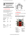
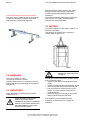
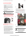
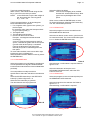
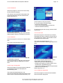
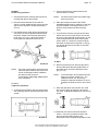
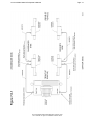
Page 35
Accu-turn Model 2200 CCD Operator’s Manual
PHASE 1
Preliminary operations:
5. Connect all the sensor cables between the
sensors and the console.
1. Assemble the frame, following the instructions
provided with the accessory itself.
NOTE:
2. Place the frame between the unit and the
vehicle, on a flat, stable surface, leaving enough
space for the sensors to be placed later (Fig.
5.2.4-2).
6. Start up the aligner and select the USER
CALIBRATION program to make the on-line help
function available. If the help function is not
present, the procedure will still remain the
same.
3. Use a spirit level to check and correct the level
of the frame in both longitudinal and transverse
directions. Adjust each of thefour feet with its
knob (a Fig. 5.2.4-2.1). When the system is
level, tighten the adjustment foot lock-nut.
The wires must remain connected though
out the procedure.
7. Turn off all four sensors using the push button
switch on the front of each sensor. One sensor
at a time, press and hold the CAL button on the
sensor keypad assembly while switching the
sensor back on. Keep CAL pressed until all
the LEDs on that sensor except the 0° LED go
out. Repeat this same procedure on the other
three sensors.
5.2.4-2
5.2.4-2.1
NOTE:
Once the correct position and level of the
frame has been obtained, the frame must
not be moved again until the calibration
procedure on the sensors in
combinations (1,2,3,4 Fig. 5.2.4-2.2) has
been completed.
PHASE 2
Calibration operation:
4. To simplify the procedure, the four sensors with
self-centering clamps should be attached to the
vehicle.
8. Remove the sensors from the front right-hand
and front left-hand clamps and place them on
the shafts at the end of the calibration frame
(Fig. 5.2.4-3).
NOTE:
In the next steps, when pressing the CAL
button of a sensor mounted on the
calibration frame, use only enough
pressure to depress the button so as not
to deflect the shaft the sensor is mounted
on.
9. Place the spirit level on the sensor arm, level
and lock it in place by tightening the sensor
lock knob. Repeat this operation on the second
sensor.
5.2.4-3
5.2.4-2.2
10. Press the CAL button of the front left-hand
sensor. The red 0° LED starts to flash, then
goes out and the LED indicating 180°
illuminates instead. Repeat the operation in the
Accu-turn Model 2200 CCD Release #01 February 2001
Accu reserves the right of modification without notice.