1
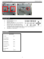
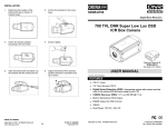
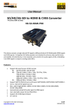
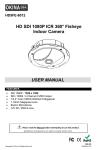
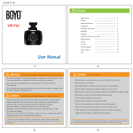
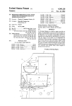
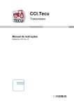
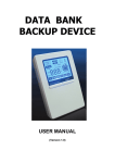
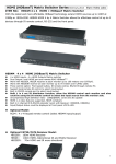
SIR36-870VF650LP
700 TVL Long Distance Smart Shift
36 IR License Plate Capture Camera
USER MANUAL
FEATURES
•
•
•
•
•
•
•
•
700 TVL
1/3” Sony Exview HAD CCD II
6.0~50.0mm Varifocal 1.3 Megapixel Lens
36 IR LED; Distance up to 200ft / 60m
Mechanical IR Cut Filter
1100mA max @ Boot up
1250mA max @ IR on ; 260mA max @ IR off
12V DC / 24V AC
IP67 Rating
Please read the Manual before attempting to use this product.
Specifications and appearance are subject to change without notice.
** THIS CAMERA IS DESIGNED FOR LICENSE PLATE CAPTURE **
L-819
Copyright © 2014. All Rights Reserved.
R201407-V24
License Plate Capture Series
SIR36-870VF650LP
Disposal of Old Electrical & Electronic Equipment (Applicable in the European Union and other
European countries with separate collection systems.)
This symbol on the product or on its packaging indicates that this product shall not be treated as household waste.
Instead it shall be handed over to the applicable collection point for the recycling of electrical and electronic
equipment. By ensuring this product is disposed of correctly, you will help prevent potential negative consequences
for the environment and human health, which could otherwise be caused by inappropriate waste handling of this
product. The recycling of materials will help to conserve natural resources. For more detailed information about
recycling of this product, please contact your local city office, your household waste disposal service or the shop
where you purchased the product.
CAUTION
1. Never point the camera toward the sun
Do not expose the lens directly to the sun or to strong light as this may damage the pick-up device.
2. Handle this camera with care
Avoid any shock or bumping of the camera. Improper handling could damage the camera.
3. Requires a proper operating environment
This camera is designed for indoor use. The allowable temperature range for operation of this camera is
between 14°F ~ 122°F / -10°C ~ 50°C.
4. Clean the front face or lens
It is recommended that the surface be cleaned every 3~6 months. Cleaning should be done by using a chamois,
a very fine soft cloth, lens tissue, or cotton tipped applicator and ethanol to carefully remove any fingerprint or
dust.
5. Check the power source voltage
The power source voltage should be within the specified range. (Camera must meet the specifications).
Camera must be connected to a surge protector at all times.
6. Objects and liquid entry
Never push objects of any kind into this camera as this may touch dangerous voltage points of short out parts
that could result in a fire or electric shock. Never spill any kind of liquid on the video product.
7. Servicing
Do not attempt to service this video product by yourself as opening or removing covers may expose you to
dangerous voltage or other hazards. Refer all service to qualified servicing personnel.
8. Damage requiring service
Unplug this video product from the wall outlet and refer service to qualified servicing personnel under the
following conditions
a. When the power supply cord or plug is damaged.
b. If liquid has been spilled, or objects have fallen into the video product.
c. If the video product has been exposed to rain or water.
d. If the video product has been dropped or the cabinet has been damaged.
e. When the video product exhibits a distinct change in performance.
FCC STATEMENT
This device complies with Part 15 FCC Rules. Operation is subject to the following two conditions:
(1) This device may not cause harmful interference.
(2) This device must accept any interference received including interference that may cause undesired operation.
* Federal Communications Commission (FCC) Statement
This Equipment has been tested and found to comply with the limits for a Class B digital device, pursuant to Part
15 of the FCC rules. These limits are designed to provide reasonable protection against harmful interference in a
residential installation. This equipment generates uses and can radiate radio frequency energy and, if not installed
2
License Plate Capture Series
SIR36-870VF650LP
and used in accordance with the instructions, may cause harmful interference to radio communications. However,
there is no guarantee that interference will not occur in a particular installation. If this equipment does cause
harmful interference to radio or television reception, which can be determined by turning the equipment off and on,
the ser is encouraged to try to correct the interference by one or more of the following measures:
- Reorient or relocate the receiving antenna.
- Increase the separation between the equipment and receiver.
- Connect the equipment into an outlet on a circuit different from that to which the receiver is connected.
- Consult the dealer or an experienced radio/TV technician for help.
* You are cautioned that changes or modifications not expressly approved by the party responsible for compliance
could void your authority to operate the equipment.
LIMITED WARRANTY
OKINA USA products are covered under warranty for one (1) year from the date of purchase. The warranty will
automatically be voided if any of the following occurs:
1. Camera sticker is removed
If the camera sticker is removed, we will not be able to confirm any information regarding when and where the
product was purchased. We have no other way to verify the purchase record without the serial number on the
camera sticker; therefore, it should not be removed.
2. Camera is modified in any way
If the camera is scratched, damaged, or modified in a manner not described in this manual, the warranty will be
voided immediately. It is the customer’s responsibility to keep the camera in good condition.
3. Video or power cable is cut
The video cable and the power cable should not be tampered with. Cutting or modifying of the cables will result
in termination of the warranty.
TABLE OF CONTENTS
FEATURES ............................................................................................................................................................. 1
SAFETY PRECAUTIONS ....................................................................................................................................... 2
FCC STATEMENT ............................................................................................................................................... 2-3
LIMITED WARRANTY ............................................................................................................................................ 3
PACKAGE CONTENTS ......................................................................................................................................... 4
DIMENSIONS ......................................................................................................................................................... 4
FUNCTIONS .......................................................................................................................................................... 5
VIDEO, POWER AND DATA OUTPUT JACK .............................................................................................. 5
LENS AND OSD ADJUSTMENT DIP FUNCTIONS .................................................................................. 5-6
CABLE MANAGEMENT BRACKET ...................................................................................................................... 6
OSD KEYPAD ....................................................................................................................................................... 6
OSD MENU ....................................................................................................................................................... 6-16
RULES TO DESIGN LICENSE PLATE CAPTURE CAMERA ......................................................................... 17-18
RECOMMENDED CAMERA KEYBOARD CONTROLLER ........................................................................... 18-19
SPECIFICATIONS ................................................................................................................................................. 20
3
License Plate Capture Series
SIR36-870VF650LP
PACKAGE CONTENTS
1.
2.
3.
4.
5.
6.
One (1) SIR36-870VF650LP LPC Camera
Four (4) Wall Mounting Screws
Four (4) Wall Anchors
One (1) Rubber Washer
One (1) Sticker Mounting Template
One (1) User Manual
* For any returns, please include all components listed
above with original packaging in Resalable Condition.
Absolutely No Returns will be accepted if any
component is missing/damaged.
DIMENSIONS (Unit: inches / mm)
4
License Plate Capture Series
SIR36-870VF650LP
FUNCTIONS
The camera includes auto white balance mode (AWB) auto capture and color temperature.
The range is 2400°K~9600°K.
SENSOR:Auto Cell Device Sensor, the IR LED would on when night comes to make up lightness. IR LED would
not on in the day, to reduce power consumption.
LENS: Super sensitivity IR light
IR LED: Super power LED
VIDEO, POWER AND DATA OUTPUT JACK
F(BNC) JACK is for video output. DC JACK is for the power in, it is necessary to use a constant voltage adapter.
Data (RS485) to connect to controller for OSD setting.
1. Please use suitable adapter DC12V ± 10 %,
1.5A. Otherwise, this product will be damaged
2. Please use AC24V ± 10%. Otherwise, this
product will be damaged
LENS AND OSD ADJUSTMENT DIP FUNCTIONS
Unscrew the back of the device, the DIP switches can be seen under the cover. The DIP switches are adjustable
and waterproof. The details of the functions are shown below.
5
License Plate Capture Series
SIR36-870VF650LP
Remove the focus/zoom knob cover to access adjustment knobs.
OSD KEYPAD
1.
2.
3.
4.
5.
6.
7.
8.
NC (No function)
D/N, day and night switcher
NC (No function)
Reflection LED switch (for 18 pcs of reflection
LED) : IR on / IR off
Piranha LED (for 18 pcs of Piranha LED) low /
high power switch : IR1 (high) / IR low (1L)
Reflection LED (for 18 pcs of reflection LED)
low/high power switch : IR2 (high) / IR low (2L)
**IR Distance 250ft / 80m (36pcs IR LED: 18pcs Piranha / 18pcs Reflection)**
LED light on / off (is the IR light on control board)
OSD direction / enter button
OSD MENU
MAIN MENU
1. LENS
DC↲
2. EXPOSURE
↲
3. BACKLIGHT
OFF
4. WHITE BAL
ATB
5. DAY&NIGHT
EXT↲
6. SMART 3DNR
OFF
7. DE-FOG
OFF
8. FUNCTION
↲
9. EXIT
SAVE↲
6
License Plate Capture Series
Setup menu description.
Menu Item
Lens
Exposure
Backlight
White Balance
Day & Night
Smart 3DNR
De-fog
Function
Exit
SIR36-870VF650LP
Description
Defines the lens brightness and iris speed.
Defines the method of iris control.
Defines the highlight compensation (HLC), backlight compensation (BLC), and high
spotlight compensation (HBLC) set up.
Defines the white balance (WB) set up
Defines the day/night (D/N) set up
Defines the digital noise reduction set up
Defines the defog set up
Defines motion detection, privacy, digital effect, image adjustment, autofocus,
language and OSD color set up
Exits the menu and returns to live mode
To access the setup menu:
1.
Press the OSD control pad (Enter) or Coaxial Control Enter button to access the Main menu and its
submenus.
2.
Push the pad up, down, left and right or Coaxial Control TELE, WIDE, NEAR and FAR button to
move between menu options.
3.
Press the OSD control pad Coaxial Control Enter button to select an option.
4.
When is a sub menu, select “RETURN” to return to the previous menu.
5.
To exit the Main menu, move the cursor to EXIT at the bottom of the screen and press Enter. All
changes are saved.
Select the lens
In the Setup menu, go to Lens and select the type of lens used with the camera. Select DC to
adjust the lens setting manually.
1. LENS
DC LENS
1. BRIGHTNESS
40
3
2. IRIS SPEED
3. RETURN
RET↵
1-1 Brightness: Select the Brightness level, value from 1 to 100.
1-2 Iris Speed: Select the Iris speed, value from 1 to 5.
2. EXPOSURE
In the Setup menu, go to Exposure and press Enter, the below figure a shows the different options available:
Exposure menu
2-1 Shutter
2-1-1 1/60: Fixed shutter(1/50 for PAL, 1/60 for NTSC)
2-1-2 MANUAL: defines manual shutter value. Select a higher value to see movement and a lower value to see
clearer images. The values range from 1/50(1/60) to 1/100000
7
License Plate Capture Series
SIR36-870VF650LP
※ Shutter speed corresponding with car speed
Shutter Speed
Car Speed
1/60 ~ 1/120
6~12mph / 10~20km
1/150 ~ 1/300
18~37mph / 30~60km
1/310 ~ 1/500
37~50mph / 60~80km
* The table above is only for reference.
Camera to Object Distance
100~130ft / 30~40m
50~65ft / 15~20m
15~30ft / 5~10m
2-1-3 FLK: flicker mode avoids interference from light sources.
2-1-4 AUTO: the camera sets the optimum shutter speed. User can define the maximum shutter speed in AUTO
mode. The values range from FLK to 1/100000.
2-2 AGC
Adjust the maximum automatic gain control level, used in low-high conditions with the iris fully open. The values
range from 0~255.
2-3 Sens-up
The setting refers to the amount of light being allowed to load on the sensor from 2-times the “normal” light up to
256-times the “normal” light. This method can allow for brilliant, clear color images to be taken in nearly total
darkness. The values range from x2 to x256.
3. BACKLIGHT
In the setup menu, go to Backlight and select the options (DWDR, HLC, BLC, or OFF) to be modified in the
menu. Note this can be set up only if DAY & Night is on Color mode.
3-1 DWDR Menu
Digital wide dynamic range (DWDR) allows you to see details of objects in shadows of details of objects in bright
areas of frames that have high contrast between light and dark areas such as the headlights of passing car.
DWDR
1. LOW LEVEL
12
2. HIGH LEVEL
3
3. RETURN
RET↵
3-1-1 Low level: Set the low level of DWDR. The values range from 0 to 15
3-1-2 HIGH level: Set the high level of DWDR. The values range from 0 to 15
3-2 BLC Menu
BLC(backlight compensation) can improve image quality when the background illumination is high. It prevents
the object in the center from appearing too dark.
BLC
1. VALUE
MIDDLE
2. AREA
SINGLE↵
3. DEFAULT
↵
4. RETURN
RET↵
3-2-1 Value: set the value level of backlight compensation. The values range from low to high.
3-2-2 Area: set the area of the backlight compensation by position and the size. If need to define two backlight
areas, please select Double.
3-2-3 Default: reset to default the backlight compensation setting and area.
3-3 HSBLC Menu
HSBLC (high spotlight backlight compensation) masks strong light sources, giving darker areas more detail. It is
often used to help identify vehicle license plate numbers, for example. Especially users can adjust and select
the special requirements area to observe the target object under the strong spots of light exist.
8
License Plate Capture Series
SIR36-870VF650LP
HSBLC
1. GAIN
50
2. MODE
NIGHT ONLY
3. MASK LEVEL
70
4. DEFAULT
↵
5. M. SKIP AREA
OFF
6. RETURN
RET↵
3-3-1 Gain: adjust gain value. The values range from 0 to 100.
3-3-2 Mode: only when the HSBLC is enabled. It can be set to Night ONLY or ALL DAY.
3-3-3 Mask level: define the mask level. The values range from o to 100.
3-3-4 Default: reset to default the backlight compensation setting and area.
3-3-5 Mask skip area: set the value to ON or OFF to enable or disable mask skip area.
4. WHITE BAL
White balance(WB) tells the dome camera what the color white looks like. Based on this information, the dome
camera will then continue to display all colors correctly even when the color temperature of the scene changes
such as from daylight to fluorescent lighting., for example.
In the setup menu, go to White Bal and select the options to be modified:
Menu Item
ATW
AWB
AWC –SET
MANUAL
Description
ATW(automatic tracing white balance) will be used depends on the lighting
condition selected. It ensures reliable color reproduction when lighting conditions
change frequently.
AWB(auto white balance). The camera adjusts the WB itself
WB is automatically adjusted to the current environment and lock it at this value
Manually adjust the white balance by blue gain only. The red gain is automatically
adjusted when the blue gain is changed. Only use this function when there is steady
light.
MANUAL WB
1. BLUE
31
2. RED
3. RETURN
20
RET↵
5. DAY & NIGHT
In the main menu, select Day & Night to open the day/night menu. The Day & Night mode has four options: Auto,
Ext, B/W and Color.
5-1 Auto Mode
Select Auto so that the camera can automatically switch between day (color) and night (black and white) mode
Delay: This is the time in seconds before Day↔Night switches. A long delay response would be used, for
example, to avoid switching from Night to Day mode when car headlights pass in front of the camera. The values
range from 0 to 15.
Day → Night: Set the threshold level on how dark it should be before switching from Day to Night mode. Lower
(Higher) value makes the camera switched from Day to Night at lower (higher) illumination. The values range
from 16 to 176.
9
License Plate Capture Series
SIR36-870VF650LP
Night → Day: Set the threshold level on how light it should be before switching from Night to Day mode. The
values range from 0 to 160.
D&N Auto
1. DELAY
5
2. D→N(AGC)
95
3. N→D(AGC)
4. RETURN
10
RET↵
5-2 Ext mode
Select Ext to manually set the time in seconds before Day↔Night switches.
The values range from 0 to 15
D & N EXT
1. DELAY
5
2. RETURN
RET↵
5-3 B/W Mode
Select BW to manually set the camera to black and white mode.
D & N BW
1. BRUST
OFF
2. IR SMART
OFF
3. RETURN
RET↵
5-3-1 Burst: Enable/disable the color burst component of the video signal when the camera switches to B/W.
(1)
ON mode maintains the same color signal in B/W so that the video signal provides better compatibility
with certain color equipment.
(2)
OFF mode removes the color burst signal B/W video and increase the total TV lines.
5-3-2 IR Smart Mode
5-3-2-1 Value of this is for Light suppression form 0 to 100.
5-3-2-2 AREA setup; you can set up which location will be the base for detection foundation. “Position”, “size” by
using sticks control “up”, “down”, “lift”, “right” four way.
5-3-2-3 IR DWDR; Normally DWDR is for light balance in day time, but this function is for night time to balance
the light source, Value from 1 to 15.
5-4 Color Mode
Select Color to manually set the camera to color (day) mode.
10
License Plate Capture Series
SIR36-870VF650LP
6. SMART 3DNR
Smart 3D noise reduction reduces the background noise in a low luminance environment with 2D + 3D filtering
system In the main menu, select SMART 3DNR to set up noise reduction.
SMART 3DNR
1. VALUE
80
2. SMART NR
ON
100
3. SMART LEVEL
25
4. SENSITIVITY
5. RETURN
RET↵
6-1 Value
Set the desired 3DNR value. The values range from 1 to 200
6-2 Smart NR
Enable or disable the smart NR. Three dimension noise reductions.
6-3 Smart level
Set Smart NR level, the values range from 1 to 200
6-4 Sensitivity
Set the Smart NR sensitivity for activation. The values range from 1 to 200
7. DE-FOG
The feature will help to improve visibility of camera during poor weather conditions, e.g., foggy, smog.
In the main menu, select DE-FOG to enable the feature. There are three options: Off, auto and manual.
DE-FOG MANUAL
1. LEVEL
14
3
2. COLOR GAIN
3. EDGE GAIN
3
4. GAMMA
5. RETURN
7-2-1
7-2-2
7-2-3
7-2-4
0.55
RET↵
Level: set the level of de-fog. The values range from 0 to 31.
Color gain: set the level of color gain. The values range from 0 to 10
Edge gain: set the level of edge gain. The values range from 0 to 10
Gamma: set the level of gamma. The values range from 0.05 to 1.00
11
License Plate Capture Series
SIR36-870VF650LP
8. FUNCTION
There are additional functions are available in this section. In the main menu, select function and press enter,
the below figure shows the different options available.
FUNCTION
1. MOTION
OFF
2. PRIVACY
OFF
3. D-EFFECT
↵
4. IMAGE ADJ
↵
5. COMM ADJ
↵
6. SYNC
INT
7. LANGUAGE
ENGLISH
8. OSD COLOR
1
9. RETURN
RET↵
Menu Item
Motion
Privacy
D-effect
Image adj
Comm adj
Sync
Language
OSD color
Return
Description
Set the motion detection
Set the privacy mask
Set digital effect
Set the image adjustment
Set the communication protocol settings
Set the synchronization/ Line lock in 24V AC
Set the OSD language
Set the OSD color
Exits the menu and returns to live mode
8-1 Set Motion Detection
In the function menu, go to motion and press Enter, the below figure shows the different options available.
8-1-1 Area: Select the motion detection zone (AREA1, AREA2, AREA3 and AREA4) that you want to configure.
The selected zone will keep blinking.
8-1-2 Area display: Choose whether to enable motion detection for the selected zone. If enabled, you can also
customize the position and size of the zone.
8-1-3 Value: Set the sensitivity level for the motion trigger. When Sensitivity level is high, motion detection can
be triggered even by the slightest of movement. The values range from 0 to 100.
8-1-4 Motion view: Choose whether to show motion blocks when the camera detects motion in the selected
zone.
8-2 Privacy Setup
With this function, you can choose to mask areas that you want to hide on the screen to protect your privacy. You
can mask up to 8 areas using a variety of colors
In the function menu, go to privacy and press Enter, the below figure shows the different options available
12
License Plate Capture Series
SIR36-870VF650LP
8-2-1 Area: Select the privacy mask (AREA1 to AREA8) that you want to configure. Each privacy mask is
already associated with a pre-selected color which you can change using the COLOR setting.
8-2-2 Area display: Choose whether to enable the selected privacy mask. If enabled, you can also customize the
position and size of the privacy mask.
8-2-3 Color: defines the color of the privacy mask. There are 16 colors available.
8-2-4 Transpar: defines the level of transparency of the privacy mask. The values range from 0 to 3.
8-3 Digital Effect Setup
In this function menu, go to D-EFFECT and press Enter. The figure below shows the different options available.
D-EFFECT
1. D-ZOOM
OFF
2. SMART DZOOM
OFF
3. DIS
OFF
4. FREEZE
OFF
5. MIRROR
OFF
6. NEG. IMAGE
OFF
7. RETURN
RET↵
8-3-1 D-Zoom
When the digital zoom is enabled, in live video the camera will zoom in then zoom out on a specific area chosen
by user
8-3-1-1 Range: digital zoom in / out. The values range from x1 to x32
8-3-1-2 Pan: Set pan location when D-zoom is activated. The values range from -100 to +100
8-3-1-3 Tilt: Set tilt location when D-zoom is activated. The values range from -100 to +100
8-3-2 Smart D-Zoom
When a motion is detected in a specific area chosen by user, it will zoom in on the area then zoom out
13
License Plate Capture Series
SIR36-870VF650LP
8-3-2-1 Range: set the zoom in / out. The values range from x2 to x5.
8-3-2-2 Position: defines the zoom area. When a motion is detected, it can automatically zoom in/out.
8-3-2-3 Sensitivity: set the sensitivity level for activation (ranged from 0 ~100).
8-3-2-4 Time: Defines the desired stay time value for display of zoom in/out (0~15 seconds)
8-3-3 DIS
The DIS function (digital image stabilizer) helps to neutralize light camera vibrations.
8-3-4 FREEZE
The FREEZE function helps to hold the image to analyze precisely.
8-3-5 MIRROR
The MIRROR function helps change the orientation of the image: horizontally reversed (MIRROR), upside down
(V-FLIP) or horizontally reversed upside down (ROTATE). Using this mode does not affect the orientation of text
on the screen.
8-3-6 NEG. IMAGE
The NEG IMAGE Display the image in a negative exposed format
8-4 Image Adjustment
The figure below shows the different options available
IMAGE ADJ
1. SHARPNESS
---
2. MONITOR
LCD↵
3. LENS SHADING
OFF
4. DEFECT
↵
5. RETURN
RET↵
Sharpness: defines how crisp your images will be. Setting the sharpness too high will make your pictures look
pixelated, like old computer graphics. On the other hand, setting the sharpness too low will make everything
look soft and blurry. The values range from 0 to 31.
In the image adjustment menu, select sharpness to change the value by pressing LEFT or RIGHT.
Monitor: Select the monitor type which is closest to the type you are using. In the Monitor submenu, you can also
manually adjust GAMMA, BLUE GAIN, and RED GAIN levels for the selected monitor type.
8-4-1 CRT Mode
Ped level: defines the master pedestal level value. The values range from 0 to 63.
Color gain: Adjust the saturation of the color from off (black & white) (0) to oversaturated (255)
8-4-2 LCD Mode
MONITOR LCD
1. GAMMA
---
2. PED LEVEL
30
3. COLOR GAIN
4. RETURN
128
RET↵
14
License Plate Capture Series
SIR36-870VF650LP
Gamma: Gamma correction controls and adjusts the overall brightness of an image for consistency. The values
range from 0.05 to 1.00
Ped level: defines the master pedestal level value. The values range from 0 to 63.
Color gain: Adjust the saturation of the color from off (black & white) (0) to oversaturated (255)
8-4-3 Set Lens shading:
Enable to brighten the edges of the camera image.
Level: set the level of lens shading correction. The values range from 0 to 60.
H-Center: set center location in horizontal side. The values range from 0 to 255.
V-Center: set center location in vertical side. The values range from 0 to 255
8-4-4 Defect: In case, the camera’s image sensor may have a certain number of defective pixels., which could
be due to operation conditions responding to light exposure differently than surrounding pixels. Which the
Defective Pixel Correction (DPC) function, you can enable the camera to digitally correct defective pixels using
its image signal processor.
8-4-4-1 Sensup: Adjust the magnification of existing light sources to make it easier for the
camera to pick up defective pixels. If set too strong, the camera can mistake regular noise as defective pixels.
The values range from x4 to x128.
8-4-4-2 Diff: defines difference value against around pixels to find dead pixel. It can find big size of dead pixel
with bigger values. The values range from 0 to 3.
8-4-4-3 Threshold: defines threshold value. The values range from 0 to 4.
8-4-4-4 Start: Perform STATIC DPC. The camera closes the lens automatically and detects defective pixels that
exceed the specified level.
8-5 Setup the Protocol Adjustment
In function menu, go to comm adj, the below figure shows the different options available.
COMM ADJ
1. CAM TITLE
OFF
2. PROTOCOL
PELCO-D
3. RS485
↵
4. RETURN
RET↵
8-5-1 Set Camera title
The camera ID displayed on-screen can have up to 53 characters.
15
License Plate Capture Series
SIR36-870VF650LP
To enter a character, move the cursor to the desired character and press Enter & select it. It appears in the input
line. Repeat the process until all characters are entered.
To move the character, input position in the input line, move the cursor in the command line to ← or → and press
Enter.
To clear the input line, move the cursor to CLR and press Enter.
To delete a character in the input line, select the character so that it blinks. Then move the cursor to CLR on the
command line and press Enter.
To position the camera ID on-screen, move the cursor to POS and press Enter. The menu will then disappear
on-screen and the camera ID will be displayed on the monitor. Use the menu button to move the camera ID to
the desired position.
Press Enter. The menu will reappear. Select Return to return to the previous menu.
8-5-2 PROTOCOL
Two protocols are available for remote control with a RS485 controller or keyboard Pelco-D and Pelco-P, use the
LEFT or RIGHT to choose the protocol
8-5-3 RS485
This function allows you to configure the camera’s RS485 protocol settings.
RS485
1. CAM ID
1
2. ID DISPLAY
OFF
3. BAUDRATE
9600
4. RETURN
RETvalues
↵
Camera
ID: set the camera id. The
range from 1 to 255.
ID display: enable or disable the id display on screen. Press LEFT or RIGHT enable or disable.
Baud rate: defines the baud rate between camera and controller. The values range from 2400 to 57600.
8-6 SYNC INT
Use the Sync menu to display the current synchronization mode. Only one option available: Internal (DC12V).
8-7 OSD language
16 languages are available, press RIGHT or LEFT to choose the language.
ENGLISH, KOREAN, JAPANESE, CHINESE TRADITIONNAL, CHINESE SIMPLIFIED, RUSSIAN, FRENCH,
ESPANOL, ITALIAN, PORTUGUESE, DUTCH, GERMAN, POLISH, TURKISH, HEBREW, ARABIC
8-8 OSD COLOR
Value from 1~6,
9. EXIT
User can return to the upper level of the OSD or save current setting and exit the OSD.
Press RIGHT or LEFT to choose the value and press Enter to validate.
16
License Plate Capture Series
SIR36-870VF650LP
RULES TO DESIGN LICENSE PLATE CAMERA
1. Location and Trajectory
Please note the following diagram:
In order to obtain the most optimal image, place the camera where it can obtain a clear, straight view of the
license plate. A low angle is recommended to get the clearest license plate images.
YES
YES
Low Angle
NO
NO
High Angle
2. Focusing and Shutter Speed
Focusing is the most important thing. It is recommended that the focusing should be done on the license plate of
a parked vehicle. It will take time to focus. An example of shutter speed is shown below:
Before
※ Shutter speed corresponding with car speed
Shutter Speed
Car Speed
1/60 ~ 1/120
6~12mph / 10~20km
1/150 ~ 1/300
18~37mph / 30~60km
1/310 ~ 1/500
37~50mph / 60~80km
* The table above is only for reference.
After
Camera to Object Distance
100~130ft / 30~40m
50~65ft / 15~20m
15~30ft / 5~10m
Shutter speeds of 1/250 and 1/500 are the recommended settings.
Please use the chart in the installation manual when selecting shutter speed.
3. 1/7 Screen Area
In order to ensure optimal images, make sure the camera is focus to that the license plate will take up at least
1/7 total width of the viewable screen area. If the drive way is too wide, you must add more cameras to cover the
area.
17
License Plate Capture Series
SIR36-870VF650LP
4. High Resolution and FPS Setting for DVR
The quality of the DVR used is also an important factor for this application.
A high-resolution DVR capable of recording at 20 to 30 FPS per channel is the minimum requirement for
recording of SIR36-870VF650LP images. To have optimal recorded playback performance, a 30 FPS DVR is
suggested.
RECOMMENDED CAMERA KEYBOARD CONTROLLER
PTZ-KB050
PTZ-KB050X
PTZ-KB250X
For night time OSD settings, it is better to use a keyboard controller. Please refer to keyboard controller’s user
manual for how to pull out the OSD menu from camera.
Quick setup for License Plate Capture (below OSD setting must be done at night).
After mounted the camera and focused with parked vehicle (Headlight On), Please enter to OSD Setting.
18
License Plate Capture Series
SIR36-870VF650LP
Enter LENS then Under MAIN MENU, configure the BRIGHTNESS value until you can see the License Plate.
After BRIGHTNESS configuration please have vehicle drive by to see Front and Rear License Plate, it may have
an little blurring when vehicle is moving, please adjust Automatic gain control (AGC) value when during the
vehicle driving.
Go back to Main Menu to Save the setting you was make by under selection of “9 EXIT” before you exit the OSD
setup.
19
License Plate Capture Series
SIR36-870VF650LP
SPECIFICATIONS
Model
Image Sensor
Total Pixels
Effective Pixels
SIR36-870VF650LP
1/3” Sony Exview HAD CCD II
NTSC: 1028(H) x 508(V) / PAL: 1028H) x 596(V)
NTSC: 976(H) x 494(V) / PAL: 976(H) x 582(V)
Resolution
700 TV Lines
Synchronization system
Internal synchronization
Scanning system
2:1 Interlace
S/N ratio
Electronic Shutter
OSD
>48 dB (AGC off)
NTSC: 1/60, FLK 1/100, 1/110~1/2000, 1/5000~1/10000
( 1/10 step) sens-up(x2~x256, slow shutter)
Button / RS485 Control keyboard / Communication
Pelco-C, Pelco-D, Pelco-P
OSD Language
ENGLISH, JAPANESE, CHINESE TRADITIONNAL, up to 16 countries
White Balance
AWB / AWC-SET / MANUAL / ATW
Mechanical IR Cut Filter
Min. Illumination
Yes
0.1 lux @ F1.6 / 0.00039 lux (Sens-up, 256X)
Gamma Correct
0.45 / 1
Video Output
IR LED
1.0 Vp-p / 75 ohm composite
36pcs IR LED (18pcs Piranha / 18pcs Reflection)
IR Distance
Up to 200ft / 60m
Lens Type
6.0~50.0mm Varifocal Lens / F1.6 (1.3 Megapixel)
Power Source
Power Consumption
Current
12V DC ± 10% / 1.5 A / 24V AC
1100mA max @ Boot up
1250mA max @ IR on ; 260mA max @ IR off
12V DC: 1.25A / 24V AC: 820mA
IP Rating
IP67
Operating Temperature
14°F~122°F / -10°C~50°C
Storage Temperature
-4°F~158°F / -20°C~70°C
Dimension (W x H x D)
Net Weight
3.94 x 7.81 x 8.23 inches / 100 x 198.5 x 224.2 mm
3.31 lbs / 1.5kg
*Specifications are subject to change without notice.
PAL Version also available.
www.okinausa.com
MADEIN TAIWAN
Copyright © 2014. All rights reserved.
L-819
20
R201407-V24