1
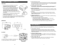
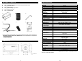
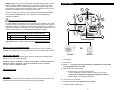
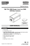
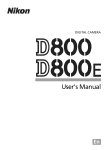
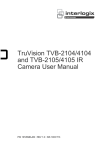
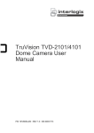
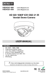
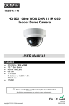
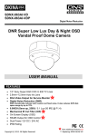
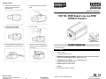
INSTALLATION 1. Determine the location of the External IR (top or bottom of camera body). 2. Put the tiny bracket on the screw base. SDNR-8700 Digital Noise Reduction 700 TVL DNR Super Low Lux OSD ICR Box Camera 3. Center the bracket position according to the two holes. 4. Screw it tightly. Optional External IR SDNR-8IR14 See page 22 for details 5. 6. Take the External IR and attach it to the bracket with the small screw tie. Adjust the External IR to desired position (forward or backward and up or down). USER MANUAL * Lens not included FEATURES 700 TV Lines 1/3” Sony Exview CCD II Digital Noise Reduction (DNR) - Dramatically reduces both random and fixed noise. It also reduces DVR disk space usage by up to 70%. 0.00039 (Sens-up, 256X) / 0.1 Lux (50 IRE @ F1.4) Built-in Microphone RCA Output RS485 Output for OSD Control 330mA Dual Power 12V DC / 24V AC MADE IN TAIWAN Copyright © 2013. All Rights Reserved. www.okinausa.com 24 T-417_T-416-IR R201310-V14 Copyright © 2013. All Rights Reserved. ** Replacing SDNR-8630 PAL version also available 1. Please read the Manual before attempting to use this product. 2. Specifications and appearance are subject to change without notice. 3. Accessory cable for other cameras. 1. 12V DC, 1A input for IR power source. 2. 12V DC, 1A output for external device (camera) power. 3. External 5V trigger. Depends on camera brand’s own mode. SWITCHES Rubber Cover DIP Switch Settings 1. Reflection LED Power: low / high 2. Reflection LED: off / on DIP Switch 3. 5Φ LED Power: low / high Disposal of Old Electrical & Electronic Equipment (Applicable in the European Union and other European countries with separate collection systems). This symbol on the product or on its packaging indicates that this product shall not be treated as household waste. Instead it shall be handed over to the applicable collection point for the recycling of electrical and electronic equipment. By ensuring this product is disposed of correctly, you will help prevent potential negative consequences for the environment and human health, which could otherwise be caused by inappropriate waste handling of this product. The recycling of materials will help to conserve natural resources. For more detailed information about recycling of this product, please contact your local city office, your household waste disposal service or the shop where you purchased the product. 4. 5Φ LED Power: off / on 1 2 3 4 Rubber Cover VR Switch Settings 1. Day and night switch time delay adjust 2. Illumination (Lux) level adjust CAUTION 1. Never point the camera toward the sun Do not expose the lens directly to the sun or to strong light as this may damage the pick-up device. 2. Handle this camera with care Avoid any shock or bumping of the camera. Improper handling could damage the camera. 3. Requires a proper operating environment This camera is designed for indoor use. The allowable temperature range for operation of this camera is between 14°F ~ 122°F / -10C ~ 50C. 2 23 4. Clean the front face or lens It is recommended that the surface be cleaned every 3~6 months. Cleaning should be done by using a chamois, a very fine soft cloth, lens tissue, or cotton tipped applicator and ethanol to carefully remove any fingerprint or dust. OPTIONAL EXTERNAL IR, SDNR-8IR14 FEATURES Total 14pcs IR LED: 4pcs Reflection & 10pcs 5Ø Parabolic reflected IR LEDs allow for even illumination of a shot on near and far objects Built-in Photodiode: Cadmium Sulfide (CdS) cells within the External IR controls the Mechanical IR Cut Filter (ICR) that’s in the SDNR-8700 camera, allowing it to detect light. So when the CdS cells detect low light, the External IR is triggered and activates the camera’s ICR to work simultaneously for best day and night images. External IR can be mounted above or below the camera and can be aimed high or low in the field of vision IR distance up to 100ft / 30m Can be used in different distance ranges and adjusts the IR high/low 5. Check the power source voltage The power source voltage should be within the specified range. (Camera must meet the specifications). Camera must be connected to a surge protector at all times. 6. Objects and liquid entry Never push objects of any kind into this camera as this may touch dangerous voltage points of short out parts that could result in a fire or electric shock. Never spill any kind of liquid on the video product. 7. Servicing Do not attempt to service this video product by yourself as opening or removing covers may expose you to dangerous voltage or other hazards. Refer all service to qualified servicing personnel. Light sensor trigger is adjustable for a range of lighting conditions Start delay can be set at different times DIMENSION 8. Damage requiring service Unplug this video product from the wall outlet and refer service to qualified servicing personnel under the following conditions: a. When the power supply cord or plug is damaged. b. If liquid has been spilled, or objects have fallen into the video product. c. If the video product has been exposed to rain or water. d. If the video product has been dropped or the cabinet has been damaged. e. When the video product exhibits a distinct change in performance. LIMITED WARRANTY OKINA USA products are covered under warranty for one year from the date of purchase. The warranty will automatically be voided if any of the following occurs: Unit: mm I/O CABLE 1. Camera sticker is removed If the camera sticker is removed, we will not be able to confirm any information regarding when and where the product was purchased. We have no other way to verify the purchase record without the serial number on the camera sticker; therefore, it should not be removed. 2. Camera is modified in any way If the camera is scratched, damaged, or modified in a manner not described in this manual, the warranty will be voided immediately. It is the customer’s responsibility to keep the camera in good condition. 3. Video or power cable is cut The video cable and the power cable should not be tampered with. Cutting or modifying of the cables will result in termination of the warranty. Just plug the External IR, SDNR-8IR, to DNR Super Low Lux Day & Night OSD Box Camera, SDNR-8700. 22 3 PACKAGE CONTENTS A. B. C. D. E. F. SPECIFICATION One (1) DNR Vandal Proof Box Camera with power/video cable One (1) Remote Control One (1) Allen Wrench One (1) Motion Relay Output Wire One (1) IRIS Connector One (1) User Manual A. B. D. C. E. 4 Model System Image Sensor DSP Total Pixel Synchronizing System Resolution Scanning System Minimum Illumination S/N Ratio Digital Noise Reduction (DNR) Day & Night Digital Zoom Auto Gain Control White Balance Back Light Compensation Picture Adjust Electronic Shutter Video Output Camera Title Sens-Up F. Refer to #4 on page 5 for details Picture Effect * For any returns, please include all components listed above with original packaging in Resalable Condition. Absolutely No Returns will be accepted if any component is missing/damaged. DIMENSION OSD Control OSD Language Mechanical IR Cut Filter (ICR) Lens Lens Type Power Source Power Consumption Power Current Operating Temperature Storage Temperature Dimension Weight SDNR-8700 NTSC 1/3” Sony Exview CCD II NVP2190 / High End ASIC Solution 1028(H) x 508(V) Internal / Line Lock 700 TV Lines 2:1 Interlace 0.00039 (Sens-up, 256X) ; 0.1 Lux (50 IRE @ F1.4) More than 50dB (AGC OFF) 3 DNR; ON / OFF(0~100) Auto / B/W / Color / EXT ON / OFF (0~32x) Low / Middle / High / OFF AWB / AWC-SET / MANUAL / ATW BLC / HSBLC / OFF / DWDR Sharpness / Monitor / Lens shading / Defect Auto 1/60 ~ 1/100,000 sec / Flk X2~X256 1.0 Vp-p / 75 ohm composite (BNC) ON / OFF ON / OFF (Selectable limit ~ 256X) Freeze / Mirror / flip / 180° rotate / D-zoom / Smart D-zoom / Neg. image / DIS Button / RS485 Control keyboard / Communication Pelco D,P ENGLISH, CHINESE, JAPANESE, up to 16 countries Auto / Day / Night Not Included C/CS, DC/Video 12V DC / 24V AC ± 10% / 1A 2.5W 330mA (Max) 14°F ~ 122°F / -10°C ~ 50°C -4°F ~ 158°F / -20°C ~ 70°C 127.2(W) x 52.3(H) x 69.3(D) mm 0.79 lbs / 360 g * Specifications are subject to change without notice. Note: PAL version also available Unit: mm 4 21 SPECIAL menu: User can setup Camera title, Digital effect (Freeze, Mirror, V-FLIP, Rotate, D-ZOOM, GAMMA), RS485 which is very useful to connect test monitor, DVR or keyboard to do the camera setting (Gamma ratio, Negative image effect, Motion detection, Privacy mask and language choice). SYNC INT is only in 12V DC power source. SYNC INT and L/L (line lock) are in 24V AC. REAR PANEL 1 2 The key combination to enter the camera’s OSD menu with OKINA USA’s RS485 PTZ controller PTZ-KB250X is SET + 95 + PRESET and for PTZ-KB050X is PRESET+95+ENTER. 6 The protocol must be set to Pelco-D (not P) For other RS485 PTZ controllers, the key combination may be different. If you have trouble accessing the camera OSD, first check the wiring for polarity and continuity, then please contact your reseller tech support. Note that there are a lot of different RS485 PTZ controllers in the market, so our tech support staff is limited to only a few brands. The best option is to use OKINA USA’s RS485 PTZ controllers. 7 5 3 RS485 PTZ Controller Key Combination to Enter OSD Menu 1. PTZ-KB250X SET + 95 + PRESET 2. PTZ-KB050X PRESET + 95 + ENTER 4 OSD Control: Button / RS485 Control keyboard/ Communication Pelco D DISPLAY THE SYNCHRONIZATION MODE Use the Sync menu to display the current synchronization mode. Only one option is available: Internal (DC 12V). Line Lock mode can be chose if the power input is AC 24V SET UP OSD LANGUAGE Use this menu to select the OSD language. There are 16 languages available, press RIGHT or LEFT to choose the language. OR PTZ-KB250 PTZ-KB050X 1. Video Output ENGLISH, KOREAN, JAPANESE, CHINESE TRADITIONNAL, CHINESE SIMPLIFIED, RUSSIAN, FRENCH, ESPANOL, ITALIAN, PORTUGUESE, DUTCH, GERMAN, POLISH, TURKISH, HEBREW, ARABIC 2. Audio Output 3. RS485, +/- – See page 12 for PTZ controller key combination to call up OSD menu and page 10 for wire & cable 4. MDO, Motion Detect Relay Output SET UP OSD COLOR Value 1-6. a. Black & Brown = for External Alarm Device. Set up on OSD Menu: Special Motion Motion View: On/Off See page 11 for OSD setting and page 8 for application diagram EXIT MENU User can return to the upper level of the OSD or save current setting and exit the OSD. Press RIGHT or LEFT to choose the value and press Enter to validate. b. Red & Orange = not working for this model 5. 12V DC~24V AC, dual power 6. External IR (optional) – See page 15 for more details 7. On-Screen Display (OSD) Control 20 5 OPERATION The Main menu provides access to the camera configuration options. The on-screen display (OSD) is only available in multi languages, such as English, Korean, Traditional Chinese, Simplified Chinese, Japanese, Russian, French, Spanish, Italian, Portuguese, Dutch, German, Polish, Turkish, Hebrew, Arabic. Program the camera by attaching a standard video monitor to the system. OSD Button Menu: To enter a character, move the cursor to the desired character and press Enter to select it. It appears in the input line. Repeat the process until all characters are entered. To move the character, input position in the input line, move the cursor in the command line to ← or → and press Enter. To clear the input line, move the cursor to CLR and press Enter. To delete a character in the input line, select the character so that it blinks. Then move the cursor to CLR on the command line and press Enter. Setup Menu Description Menu Item Lens Exposure Backlight Day & Night Smart 3DNR De-fog Function Exit Description Defines the lens brightness and iris speed Defines the method of iris control Defines the highlight compensation (HLC) and backlight compensation (BLC) set up Defines the day/night (D/N) set up Defines the digital noise reduction set up Defines the defog set up Defines motion detection, privacy, digital effect, image adjustment, auto focus, language and OSD color set up Exits the menu and returns to live mode. Save changes made. To position the camera ID on-screen, move the cursor to POS and press Enter. The menu will then disappear on-screen and the camera ID will be displayed on the monitor. Use the menu button to move the camera ID to the desired position. Press Enter. The menu will reappear. Select Return to return to the previous menu. RS485: This function allows you to configure the camera’s RS485 protocol settings. To access the Setup menu: 1. 2. 3. 4. 5. Press the OSD control pad (Enter) or Coaxial Control Enter button to access the Main menu and its submenus. Push the pad up, down, left and right or Coaxial Control TELE,WIDE, NEAR, and FAR button to move between menu options. Press the OSD control pad Coaxial Control Enter button to select an option. When in a sub menu, select “Return to return to the previous menu. To exit the Main menu, move the cursor to Exit at the bottom of the screen and press Enter. All changes are saved. 6 1. 2. 3. Camera ID: set the camera ID. The values range from 1 to 255. ID display: enable or disable the id display on screen. Press LEFT or RIGHT enable or disable. Baud rate: set the baud rate between camera and controller. The values range from 2400 to 57600. 19 SELECT THE LENS In the Setup menu, go to Lens and select the type of lens used with the camera. Select DC to adjust the lens setting manually, 1. 2. 3. 4. Sens-up: Adjust the magnification of existing light sources to make it easier for the camera to pick up defective pixels. If set too strong, the camera can regular noise mistakely as defective pixels. The values range from x4 to x128. Diff: set difference value against around pixels to find dead pixel. It can find big size of dead pixel with bigger values. The values range from 0 to 3. Threshold: set threshold value. The values range from 0 to 4. Start: Perform STATIC DPC. The camera closes the lens automatically and detects defective pixels that exceed the specified level. User need to cover the lens with the hand. SETUP PROTOCOL ADJUSTMENT In function menu, go to COMM ADJ, the below figure shows the different options available. 1. 2. EXPOSURE In the Setup menu, go to Exposure and press Enter, the below figure shows the different options available: 1. Set Camera title: The camera ID displayed on-screen can have up to 53 characters 18 Brightness: Select the Brightness level, value from 1 to 100. Iris Speed: Select the iris speed, value from 1 and 5. Shutter: 1/60: Fixed value MANUAL: defines manual shutter value. Select a higher value to see movement and a lower value to see clearer images. The values range from 1/60 to 1/100000. FLK: flicker mode avoids interference from light sources. AUTO: the camera sets the optimum shutter speed. User can define the maximum shutter speed in AUTO mode. The values range from FLK to 1/100000. 7 2. AGC: Adjust the maximum automatic gain control level, used in low-light conditions with the iris fully open. The values range from OFF to High. 3. SENS-UP: The setting refers to the amount of light being allowed to load on the sensor from 2-times the "normal" light up to 256-times the "normal" light. This method can allow for brilliant, clear color images to be taken in nearly total darkness. The values range from x2 to x256. SET BACKLIGHT In the Setup menu, go to Backlight and select the options (DWDR, HLC, BLC, or OFF) to be modified in the menu. Note that this can be set up only if DAY&NIGHT is on COLOR mode. DWDR: Digital Wide dynamic range (DWDR) allows you to see details of objects in shadows or details of objects in bright areas of frames that have high contrast between light and dark areas such as the headlights of a passing car. 1. 3. Sharpness: set image sharpness level from 0 to 31. Setting the sharpness too high will make your pictures look pixelated, like old computer graphics. On the other hand, setting the sharpness too low will make everything look soft and blurry. Monitor: Select the monitor type which is closest to the type you are using. In the Monitor submenu, there are CRT and LCD options. you can also manually adjust GAMMA, BLUE GAIN, and RED GAIN levels for the selected monitor type. Lens shading: Enable to brighten the edges of the camera image. 1. 2. 3. Level: set the level of lens shading correction. The values range from 0-60 H-center: set center location in horizontal side. The values range from 0-255. V-center: set center location in vertical side. The values range from 0-255. 2. 1. 2. Low level: Set the low level of DWDR. The values range from 0 to 15 High level: Set the high level of DWDR. The values range from 0 to 15 BLC: BLC (backlight compensation) can improve image quality when the background illumination is high. It prevents the object in the center from appearing too dark. Defect: In case, the camera’s image sensor may have a certain number of defective pixels, which could be due to operation conditions responding to light exposure differently than surrounding pixels.With the Defective Pixel Correction (DPC) function, you can enable the camera to digitally correct defective pixels using its image signal processor 8 17 Smart Zoom: When a motion is detected in a specific area chosen by user, the camera picture will zoom in on the area then zoom out. 1. 2. 3. Value: Set the value level of backlight compensation. The values range from low to high Area: Set the area of the backlight compensation by position and the size. If need to define two backlight areas, please select DOUBLE Default: Reset to default the backlight compensation setting and area. HSBLC: HSBLC (high spotlight backlight compensation) masks strong light sources, giving darker areas more detail. It is often used to help identify vehicle license plate numbers, for example. Especially users can adjust and select the special requirement area to observe the target object under the strong spots of light exist. 1. 2. 3. 4. Range: Set the zoom in times. The values range from x1 to x5. Position: Set the zoom area. When a motion is detected, it automatically zoom in/out. Sensitivity: Set the sensitivity level for activation. Time: Defines the desired time value for display of zoom in/out DIS: The DIS function (digital image stabilizer) helps to neutralize light camera vibrations. On or Off is available FREEZE: The FREEZE function helps to hold the image to analyze precisely. MIRROR: The MIRROR function helps change the orientation of the image: horizontally reversed (MIRROR), upside down (V-FLIP) or horizontally reversed upside down (ROTATE). Using this mode does not affect the orientation of text on the screen. NEG. IMAGE: The NEG IMAGE Display the image in a negative exposed format. 1. 2. 3. 4. 5. Gain: adjust gain value. The values range from 0 to 100. Mode: Only when the HSBLC is enabled. It can be set to NIGHT ONLY or ALL DAY. Mask level: Defines the mask level. The values range from 0 to 100. Default: Reset to default the backlight compensation setting and area Mask skip area: Set the value to ON or OFF to enable or disable mask skip area. SET WHITE BALANCE White balance (WB) tells the dome camera what the color white looks like. Based on this information, the dome camera will then continue to display all colors correctly even when the color temperature of the scene changes such as from daylight to fluorescent lighting, for example. SET UP IMAGE ADJUSTMENT The figure on the next page shows the different options available. 16 9 In the Setup menu, go to White Bal and select the options to be modified: Menu Item Description ATW ATW (automatic tracing white balance) will be used depends on the lighting condition selected. It ensures reliable color reproduction when lighting conditions change frequently. AWB AWB (auto white balance). The camera adjusts theWB itself AWC-SET WB is automatically adjusted to the current environment and lock it at this value. Manual Manually adjust the white balance by blue gain only. The red gain is automatically adjusted when the blue gain is changed. Only use this function when there is steady light. 2. 3. 4. Area display: Choose whether to enable the selected privacy mask. If enabled, you can also customize the position and size of the privacy mask. Color: Set the color of the privacy mask. There are 16 colors available. Transparency: Set the level of transparency of the privacy mask. The values range from 0 to 3. 0 means the mask will let user see behind the mask. 3 means the mask will entirely cover the area. SET DIGITAL EFFECT In the Function menu, go to D-effect and press Enter, the below figure shows the different options available In the main menu, select Day&Night to open the day/night menu. The Day&Night mode has three options: Auto, BW and Color. D&N Auto Mode: Select Auto so that the camera can automatically switch between day (color) and night (black and white) mode. D-Zoom: When the digital zoom is enabled, in live video the camera will zoom in on a specific area chosen by user. 1. 2. 3. Delay: This is the time in seconds before Day↔Night switches. A long delay response would be used, for example, to avoid switching fromNight to Day mode when car headlights pass in front of the camera. The values range from 0-15. Day→Night: Set the threshold level on how dark it should be before switching from Day to Night mode. Lower (Higher) value makes the camera switched from Day to Night at lower (higher) illumination. The values range from 16-176. Night→Day: Set the threshold level on how light it should be before switching from Night to Day mode. The values range from 0-160. 1. 2. 3. 10 Range: digital zoom in / out. The values range from x1 to x32 Pan: Set pan location when D-zoom is activated. The values range from -100 to +100 Tilt: Set tilt location when D-zoom is activated. The values range from -100 to +100. 15 D&N BW mode: Select BW to manually set the camera to black and white mode 1. 2. 3. 4. Area: Select the motion detection zone (AREA1, AREA2, AREA3) that you want to configure. The selected zone will be blinking. Area display: Choose whether to enable motion detection for the selected zone. If enabled, you can also customize the position and size of the zone. Value: Set the sensitivity level for the motion trigger.When Sensitivity level is high, motion detection can be triggered even by the slightest of movement. The values range from 0 to 100. Motion view: Choose whether to show motion blocks when the camera detects motion in the selected zone. 1. 2. Burst: Enable/disable the color burst component of the video signal when the camera switches to B/W. a. ON mode maintains the same color signal in B/W so that the video signal provides better compatibility with certain color equipment. b. OFF mode removes the color burst signal B/W video and increase the total TV lines. COLOR mode: Select Color to manually set the camera to color (day) mode. SET IMGE NOISE REDUCTION SET PRIVACY MASK With this function, you can choose to mask areas that you want to hide on the screen to protect your privacy. You can mask up to 8 areas using a variety of colors. Smart 3DNR noise reduction reduces the background noise in a low luminance environment with 2D + 3D filtering system. In the Main menu, select SMART 3DNR to set up noise reduction. In the Function menu, go to Privacy and press Enter, the below figure shows the different options available 1. Area: Select the privacy mask (AREA1 to AREA8) that you want to configure. Each privacy mask is already associated with a pre-selected color which you can change using the COLOR setting. 1. Value: Set the desired 3DNR value. The values range from 1 to 200. The higher is the value, the bigger is each pixel. The lower is the value, the smaller is the pixel 2. Smart NR: Enable or disable the smart NR function. Three dimensional noise reductions. Smart level: Set Smart NR level The values range from 1 to 200. The smaller 11 3. 14 4. is the value, the more visible is the noise but the sharper is the picture. The bigger is the value, the less visible is the noise but the less sharp is the picture Sensitivity: Set the Smart NR sensitivity for activation. The values range from 1 to 200. The bigger is the value, the bigger is the sensitivity 3. 4. Edge gain: Set the level of edge gain. The values range from 0 to 10 Gamma: Set the level of gamma. The values range from 0.05 to 1.00 FUNCTION SET DEFOG There are additional functions are available in this section. This feature will help to improve visibility of camera during poor weather conditions, e.g., foggy, smog. In the main menu, select function and press enter, the below figure shows the different options available. In the main menu, select DE-FOG to enable the feature. There are three options: off, auto and manual De-fog auto mode: Table 2: main menu description 1. Detect level: Set the detect level for activation. The values range from to 1-5. De-fog manual mode: Menu Item Motion Privacy D-effect Image adj Comm adj Sync Language OSD color Return Description Set the motion detection Set the privacy mask Set digital effect Set the image adjustment Set the communication protocol settings Set the synchronization Set the OSD language Set the OSD color Exits the menu and returns to live mode SET MOTION DETECTION In the function menu, go to Motion and press Enter, the below figure shows the different options available 1. 2. Level: Set the level of de-fog. The values range from 0 to 31. Color gain: Set the level of color gain. The values range from 0 to 10 12 13