1
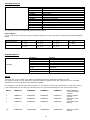
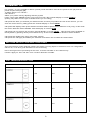
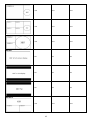
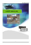
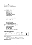
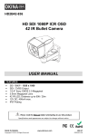
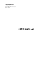
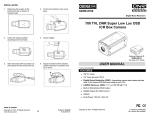
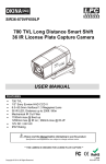
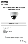
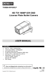
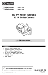
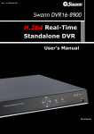
HD5FE-8012 HD SDI 1080P ICR 360° Fisheye Indoor Camera USER MANUAL FEATURES • • • • • • SDI 1080P - 1920 x 1080 SDI / HDMI / 4 Channel CVBS Output 1/3.2” Color CMOS QSXGA 5 Megapixel 1.19mm Megapixel Lens Built-in Microphone 12V DC, 550mA max. Please read the Manual before attempting to use this product. Specifications and appearance are subject to change without notice. Copyright © 2014. All Rights Reserved. HDC-39 R201402-V19 Disposal of Old Electrical & Electronic Equipment (Applicable in the European Union and other European countries with separate collection systems.) This symbol on the product or on its packaging indicates that this product shall not be treated as household waste. Instead it shall be handed over to the applicable collection point for the recycling of electrical and electronic equipment. By ensuring this product is disposed of correctly, you will help prevent potential negative consequences for the environment and human health, which could otherwise be caused by inappropriate waste handling of this product. The recycling of materials will help to conserve natural resources. For more detailed information about recycling of this product, please contact your local city office, your household waste disposal service or the shop where you purchased the product. CAUTION 1. Never point the camera toward the sun Do not expose the lens directly to the sun or to strong light as this may damage the pick-up device. 2. Handle this camera with care Avoid any shock or bumping of the camera. Improper handling could damage the camera. 3. Requires a proper operating environment This camera is designed for indoor use. The allowable temperature range for operation of this camera is between 14°F ~ 122°F / -10°C ~ 50°C. 4. Clean the front face or lens It is recommended that the surface be cleaned every 3~6 months. Cleaning should be done by using a chamois, a very fine soft cloth, lens tissue, or cotton tipped applicator and ethanol to carefully remove any fingerprint or dust. 5. Check the power source voltage The power source voltage should be within the specified range. (Camera must meet the specifications). Camera must be connected to a surge protector at all times. 6. Objects and liquid entry Never push objects of any kind into this camera as this may touch dangerous voltage points of short out parts that could result in a fire or electric shock. Never spill any kind of liquid on the video product. 7. Servicing Do not attempt to service this video product by yourself as opening or removing covers may expose you to dangerous voltage or other hazards. Refer all service to qualified servicing personnel. 8. Damage requiring service Unplug this video product from the wall outlet and refer service to qualified servicing personnel under the following conditions: a. When the power supply cord or plug is damaged. b. If liquid has been spilled, or objects have fallen into the video product. c. If the video product has been exposed to rain or water. d. If the video product has been dropped or the cabinet has been damaged. e. When the video product exhibits a distinct change in performance. LIMITED WARRANTY OKINA USA products are covered under warranty for one (1) year from the date of purchase. The warranty will automatically be voided if any of the following occurs: 1. Camera sticker is removed If the camera sticker is removed, we will not be able to confirm any information regarding when and where the product was purchased. We have no other way to verify the purchase record without the serial number on the camera sticker; therefore, it should not be removed. 2. Camera is modified in any way If the camera is scratched, damaged, or modified in a manner not described in this manual, the warranty will be voided immediately. It is the customer’s responsibility to keep the camera in good condition. 3. Video or power cable is cut The video cable and the power cable should not be tampered with. Cutting or modifying of the cables will result in termination of the warranty. 2 PACKAGE CONTENTS 1. 2. 3. 4. 5. 6. 7. 8. 9. One (1) HD5FE-8012 Camera with I/O connection cables One (1) Ceiling Cover Ring Three (3) Ceiling Mounting Screws Three (3) Ceiling Metal Bracket Holders Four (4) Wall Mounting Screws Four (4) Wall Anchors Four (4) Washers One (1) Wall Mount Template One (1) User Manual * For any returns, please include all components listed above with original packaging in Resalable Condition. Absolutely No Returns will be accepted if any component is missing/damaged. DIMENSIONS (Unit: inches / mm) 3 I/O CONNECTION 1 2 3 4 5 6 7 8 9 10 11 Label1 Label2 Label3 Label4 RS485 cable RCA cable Power cable SDI cable HDMI connector Microphone External IR Cut Trigger Camera 1 CVBS(BNC) output Camera 2 CVBS(BNC) output Camera 3 CVBS(BNC) output Camera 4 CVBS(BNC) output Purple + / White Audio output to speaker or DVR audio input 12V DC SDI connector output (BNC gold color) HDMI output to connect to a HDMI monitor Pinhole type microphone (built-in) White + / Brown (3.3V) This 360° camera can be installed into different configuration thanks to its rich connection. You will have an overview of different scenario in the next pages. A) Scenario without DVR 1. The camera uses the SDI connector output or the HDMI connector to a HD-SDI monitor that has RS485 built in connector. The user points the remote controller to the monitor and controls the camera. 2. The camera uses the SDI connector output or the HDMI connector to a HD-SDI monitor that doesn’t have RS485 built in connector. The user link the 2 RS485 wire from the camera to a keyboard controller. B) Scenario with DVR 1. The DVR only supports SDI signal input. The camera used the SDI connector output to the DVR.SDI input. The user link the 2 RS485 wire to the RS485 terminal of the DVR. The DVR uses the HDMI connector output to a HDMI monitor. The user controls the camera with the mouse or the remote controller of the DVR. 2. The DVR doesn’t have SDI signal input and only accepts analog signal. The camera uses the 4 BNC connector output to the 4 video input of the DVR. The user can’t access to the 180 and 360° view. 3. The DVR can accept both SDI and analog signal. The camera uses the SDI connector output to the DVR SDI input. The camera uses the 4 BNC connector output to the 4 video input of the DVR. The user links the 2 RS485 wire to the RS485 terminal of the DVR or to the RS485 terminal of the keyboard controller. 4 RS485 CONNECTION The 360° camera is set in protocol PELCO-D and baud rate 9600. User can use keyboard, DVR or any RS485 device to control 360° camera. Ex: keyboard RS485 port RS485 cable Purple + Positive White - Negative RS485 port 1 RJ11 Pin 3+, Pin - How to setup connection between keyboard and camera Press MENU button of keyboard for function setup CAM: 001 < MUX: 00 Setup Menu > System Menu CAM Menu DV: 00 1. 2. 3. 4. Keyboard ID Setup Master Setup CAM Type Setup Baud Rate Setup Using direction key to select system menu and then press ENTER to get in. Follow below setting and ready to control camera with command. 1. 2. 3. 4. 5. Keyboard ID Setup: Press ENT Master Setup: Press ENT CAM Type Setup: Press ENT Baud Rate Setup: Press ENT Press “ESC” to exit menu. ----- > > > > Press 1 Press ENT Esc Press 1 Press ENT Esc Choose protocol 5: PELCO-D Press ENT Esc Choose Baud Rate 1:9600 Press ENT Esc Note: If you are using others keyboard brand, please make sure the protocol setting is on PELCO-D and baud rate 9600. And the control command is same as usual. Command: The screen mode default is on mode 5. It displays in 5 windows (quad + 360°). Camera 1 ~ 4 is virtual split from 360° screen. User can control camera 1~4 like PTZ dome to do up/down/left/right movement. Control on screen in mode 5, 1. 2. 3. 4. Press Press Press Press 1 2 3 4 + + + + CAM to CAM to CAM to CAM to call call call call camera camera camera camera 1 2 3 4 and and and and after after after after to to to to use use use use joystick joystick joystick joystick to to to to move. move. move. move. Recommended Keyboard Controller for Setting Economical 2-Axis Keyboard Controller PTZ-KB050 3-Axis Keyboard Controller PTZ-KB050X 5 3-Axis Keyboard controller PTZ-KB250X ACCESS TO THE CAMERA MENU Call preset 95: displays the menu of the 360° camera Use keypad to select item. Up/down for item chooses, to right enter to sub item. Call preset 94: will apply immediately the selected mode when user is inside the camera OSD RS485 CONNECTION WITH DVR RS485 port RS485 + RS485 cable Purple + Positive White - Negative RS485 - Protocol Configuration Please go to your DVR RS485 (PTZ) setting. Select the camera and 360∘ It depends on SDI connect to which channel. If camera is on channel 1, please make sure the address is from 1 to 4. And choose protocol is PELCO-D, baud rate is 9600. Please go to your DVR PTZ control mode to start operate 360° camera. NOTE: When you are inside the camera OSD, if there is suddenly power shortage, the setting will not be saved in the memory. You must exit the OSD or wait the OSD disappears to validate the modified setting in the memory. 6 OSD OPERATION Main Menu Structure Item AE AWB BRIGHTNESS SATURATION MD MASK WDR NOISE REDUCTION DAY/NIGHT SHOW MODE PATTERN SYSTEM REBOOT Selection Submenu Submenu 1~9 1~9 Submenu Submenu OFF/MIDDLE/HIGH 00~09 Description Auto exposure Auto white balance setting Picture brightness adjust Picture saturation adjust Motion detection setting Picture mask zone setting Wide dynamic range Picture noise reduction setting AUTO means that camera will adjust automatically the mode after a period of time (0, 3, 5, 10, or 15 seconds) DAY means that camera will always be on day mode AUTO/DAY/NIGHT/EXT NIGHT means that camera will always be on night mode (black and white) EXT means that camera can adjust the mode automatically after a period of time (5, 10, or 15 seconds) Select the desired mode and then press WALL 0/ WALL 90/ WALL 180/ WALL enter button or 94 preset(keep press after 270/ DESK/ CEILING 2 beeps) Select the desired pattern and then press Mode1~model13 enter button or 94 preset(keep press after 2 beeps) Submenu System status setup Will reset the device, just press right arrow to reset it EXIT AE Submenu AE 50Hz/60Hz SHUTTER SPEED 50Hz/60Hz X3; X2; X1; AUTO; 1/100; 1/120; 1/250 Return MOTION DETECTION Submenu MD AREA MODE ACTION AREA XPOS YPOS WIDTH HEIGHT RETURN ON OFF ON/OFF 1~4 0000~1943 0000~1943 0256~1943 0256~1943 MODE AREA XPOS YPOS WIDTH HEIGHT RETURN 1~5 1~3 OFF/ON 1~4 0001~1943 0001~1943 0000~1943 0000~1943 Return MASK Submenu MASK MASK COLOR TRANSP RETURN 7 PATTERN Submenu PATTERN MODE1 Camera 1+360∘ MODE2 Camera 2+360∘ MODE3 Camera 3+360∘ MODE4 Camera 4+360∘ MODE5 Quad+360∘ MODE6 Camera 1+Camera 3+360∘ MODE7 See below for more details MODE8 180° in 16 :9 Display MODE9 360° Flat MODE10 180∘+Camera 3+Camera 4 MODE11 180∘+ 180∘ MODE12 Quad display only MODE13 360° display only When you change the pattern mode, you have to wait 10 sec until it change to selected mode. If you want to immediately see the mode please press the Enter button. Pattern Mode 7 In this mode user can choose among 4 different angle view, each can have horizontal and vertical flexibility range. View available Verticale range Horizontal range 120° D : 0~5 U : 0~5 L : 0~5 R : 0~5 140° D : 0~4 U : 0~4 L : 0~3 R : 0~3 160° D : 0~3 U : 0~3 L : 0~1 R : 0~1 180° D : 0~2 U : 0~2 0 SYSTEM Submenu CAMERA1 CAMERA2 CAMERA3 CAMERA4 AUTOFLIP SYSTEM ON/OFF ON/OFF ON/OFF ON/OFF ON/OFF If user plans to have more than 1 device in the installation Will reset the device to factory default SETID LOAD DEFAULT RETURN SET ID This function is very useful if you plan to install more than one panoramic camera on site You need to set ID on each camera by using the built in keypad, please don’t set same ID on 2 camera, otherwise the control keyboard will call them together For example if you set ID of the first camera to 1, and the ID of the second camera to 2, when you use the control keyboard you can call any camera from 1 to 8. The below table gives you the camera number SETID CAMERA1 CAMERA2 CAMERA3 CAMERA4 0 CAMERA1 CAMERA2 CAMERA3 CAMERA4 1 CAMERA1 CAMERA2 CAMERA3 CAMERA4 2 CAMERA5 CAMERA6 CAMERA7 CAMERA8 16 . . . CAMERA61 . . . CAMERA62 . . . CAMERA63 . . . CAMERA64 8 OSD (displayed next to firmware version) Nothing (Single device) SETID 01 (multi device) SETID 02 (multi device) SETID 16 (multi device) COMMAND LIST For camera 1 to 4 it is possible to define 3 preset points that will be used for the preset cruise (76) and the preset sequence display (66). To define preset 1 on camera 1 Call camera 1 Select your preset view by adjusting with the joystick Press 1 then press PRESET button 3 sec until you hear a bip (osd will display on screen POINT1) (Setting may differ from the type of RS485 device you are using) Call preset 93: After you selected your desired mode, and that you position the view of the camera, you can save the current view by calling preset 93. Osd will display on screen SAVE Call preset 66: displays each preset without transition ideal for preset whose distance is very long. In this mode the motion detection will be disabled. Osd will display on screen SCAN Call preset 76: run the auto pan function. Osd will display on screen TOUR. This function is also available on the keyboard by pressing directly AUTO PAN hot key. In this mode the motion detection will be disabled Call preset 95: displays the menu of the 360° camera Call preset 94: will apply immediately the selected mode when user is inside the camera OSD MOTION DETECTION AND TRACKING This camera has a motion detection feature and tracks a moving object in the field of view. For configuration without dvr, it can be a good alternative for live monitoring Due to the high level of processing for the CPU, it can be activated on one channel only. It doesn’t apply for 180° and 360° view. If motion detection is enable. PATTERN DESCRIPTION Pattern Preset Cruise Preset Sequence Motion Tracking Yes Yes Yes Yes Yes Yes Yes Yes Yes MODE 1 MODE 2 MODE 3 9 MODE 4 Yes Yes Yes Yes Yes Yes Yes Yes Yes No No No No No No No No No Yes Yes Yes MODE 5 MODE 6 MODE 7 MODE 8 MODE 9 MODE 10 10 MODE 11 No No No Yes Yes Yes No No No MODE 12 MODE 13 ANALOG 4 VIDEO OUTPUT Mode 1 Analog Video Mode Analog Video Yes. Only cam 1. Not Recommended. 5 Yes. Cam 1, 2, 3, 4. Recommended. 2 Yes. Only cam 2. Not Recommended. 6 Yes. Only cam 1 & 3. Not Recommended. 3 Yes. Only cam 3. Not Recommended. 7~13 4 Yes. Only cam 4. Not Recommended. NOTE: All camera angle and view can be adjusted by PTZ controller 11 No. Not Recommended. *All black screen INSTALLATION Surface Mount Step 1: Use the provided wall mount template and drill 4 holes on the wall. Step 4: Place 4 washers on the 4 mounting screws. Step 5: Screw bottom base to wall. Step 2: Cut hole for I/O Connection Cable. In-Ceiling Mount Step 1: Twist main camera cover counter clockwise to unlock. Step 3: Hammer the 4 wall anchors into the holes. Step 2: Unscrew the 4 inside metal spacer bracket screws and 1 cover attachment wire screw. Unplug the microphone wire. Copyright © 2014. All Rights Reserved. HDC-39 R201402-V19 Step 7: Put the camera into the ceiling. Step 3: Remove the cover and the inside metal spacer bracket. Step 8: Then take a screw driver and turn clockwise. The small will hit the small plastic stick of the mold until it fits the thickness of the ceiling. Do the same for the 2 other screws. Step 4: Place the 3 metal ceiling bracket holder to the ceiling cover ring. Note 1: There are no actual holes on the ceiling for the 3 mounting screws. These screws and metal ceiling bracket holders are to keep the camera from falling off the ceiling. Step 5: Put the ceiling cover ring on the camera and make sure the grey mark is visible. Note 2: User only needs to make a hole that’s larger than camera body but smaller than the ceiling cover. Use the ceiling screws / brackets to hold the camera body. Don’t need a ceiling template here. The white color pillars beside the screws are to keep brackets in proper angle while you are screwing the brackets. Step 6: Screw the cover attachment wire and plug the microphone wire back into original place and twist the main cover clockwise on the camera to lock it. 13 SPECIFICATIONS Model HD5FE-8012 Image Sensor 1/3.2” Color CMOS QSXGA (5 Megapixel : 2592x1944) image sensor Synchronizing Internal Scanning System 2:1 Interlace S/N Ratio More than 51dB Electronic Shutter X3; X2; X1; AUTO; 1/100; 1/120; 1/250 White Balance Auto WDR Angle of View OFF/Middle/ High Diagonal 185° Horizontal 185° Vertical 185° Gamma Correct 0.45 / 1 RS485 PELCO D / 9600 Video Output SDI / HDMI / 4 Channel CVBS Lens 1.19mm Megapixel Lens / F2.0 ICR Built-in Format 1080P Power Source 12V DC Jack ± 10% / 1A Power Consumption 6.6W (Max) Current 550mA (Max) Operating Temperature 14°F ~ 122°F / -10°C ~ 50 °C Storage Temperature Dimensions -4°F ~ 158°F / -20°C ~ 70°C Ø7.48 x 3.10(H) inches / Ø190 x 78.82(H) mm Ø5.71 x 3.10(H) inches / Ø145 x 78.82(H) mm (w/o ceiling cover ring) *Specifications are subject to change without notice. PAL Version also available. 14 15 www.okinausa.com MADE IN TAIWAN Copyright © 2014. All Rights Reserved. www.okinausa.com 16 HDC-39 R201402-V19