1
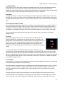
Version 1.2 User Manual
Last Revised 31 May 2013
Copyright © VSonics Limited 2010-13
1
End User License Agreement
PLEASE READ THE FOLLOWING LEGAL AGREEMENT CAREFULLY PRIOR TO USING THE VMETERS SOFTWARE PROVIDED WITH THIS AGREEMENT.
USE OF THE SOFTWARE CONSTITUTES YOUR ACCEPTANCE OF THE TERMS OF THIS LICENSE. IF YOU DO NOT AGREE TO THE TERMS OF THIS
LICENSE, PROMPTLY APPLY TO US FOR A REFUND.
1. License
The software accompanying this License, whether on disc, in memory or on any other media (the "Software"), and the related documentation are licensed
to you by VSonics Limited (the "Company"). You may use the Software on a single computer and make one copy of the Software for backup purposes
only. If you have multiple Licenses for the Software, then at any time you may have as many copies of the Software in use as you have Licenses. The
Software is "in use" on a computer when it is loaded into the temporary memory (RAM) or installed into the permanent memory (e.g., hard disk, CD-ROM,
or other storage device) of that computer, except that a copy installed on a network server for the sole purpose of distribution to other computers is not
"in use”. If the anticipated number of users of the Software will exceed the number of applicable Licenses, then you must have a reasonable mechanism
or process in place to assure that the number of persons using the Software concurrently does not exceed the number of Licenses.
2. Copy and use restrictions
You are not allowed to distribute copies of the Software or the documentation. This Software is protected by the copyright laws that pertain to computer
software. It is illegal to make copies of the Software, except for backups. It is illegal to give copies to another person, or to duplicate the Software by any
other means, including electronic transmission. The Software contains trade secrets and in order to protect them you may not decompile, reverse
engineer, disassemble or otherwise reduce the software to human-perceivable form. You may not modify, adapt, translate, rent, lease or create derivative
works based upon the Software or any part thereof. You may not provide use of the Software in a network, time-sharing, or multiple user arrangement
without purchasing the appropriate number of Licenses as described in paragraph 1. above. You may not electronically transmit the Software from one
computer to another. You acknowledge that no title to the intellectual property in the Software is transferred to you and that title and full ownership rights
to the Software will remain the exclusive property of the Company or its suppliers and licensors. If the Software is an update to a previous version (the
"Update"), you must possess a valid License for the previous version, in order to use the Update. All Updates are provided to you on a "license exchange"
basis and you agree that by using an Update, you no longer have a License to use any previous version of the Software.
3. Termination
This License is effective until terminated. You may terminate this License at any time by destroying all copies and recordings of the licensed software and
documentation and giving a legally binding written assurance to the Company that you have done so. This License will terminate immediately without
notice from the Company if you fail to comply with any provision of this License. Upon termination you must destroy all copies and recordings of the
Software, related documentation and copies thereof and return to the Company the originals of the Software and documentation.
4. Limited Warranty
The Company warrants that the Software will perform substantially in accordance with the accompanying written materials for a period of (90) ninety days
from the date of receipt.
5. Customer Remedies
The Company's entire liability and your exclusive remedy shall be, at the Company's' option, either (a) return of the price paid or (b) replacement of the
Software that does not meet the Company's Limited Warranty and that is returned to the Company with a copy of your receipt. This Limited Warranty is
void if failure of the Software has resulted from accident, abuse, or misapplication. Any replacement Software will be warranted for the remainder of the
original warranty period. This warranty gives you specific legal rights and you may also have other rights which vary by jurisdiction.
6. No Other Warranties
EXCEPT FOR THE EXPRESS WARRANTY OF THE ORIGINAL SOFTWARE SET FORTH ABOVE, THE COMPANY GRANTS NO OTHER WARRANTIES,
EXPRESS OR IMPLIED, BY STATUTE OR OTHERWISE, REGARDING THE SOFTWARE, ITS FITNESS FOR ANY PURPOSE, ITS QUALITY, ITS
MERCHANTABILITY OR OTHERWISE. THE LIABILITY OF THE COMPANY UNDER THE WARRANTY SET FORTH ABOVE SHALL BE LIMITED TO THE
AMOUNT PAID BY THE CUSTOMER FOR THE PRODUCT.
7. No Liability For Consequential Damages
In no event shall the Company or its suppliers be liable for any damages whatsoever (including, without limitation, direct, indirect, punitive, special,
incidental, or consequential damages, or damages for loss of business profits, business interruption, loss of business information, or other pecuniary loss)
arising out of the use of or inability to use the Software, even if the Company has been advised of the possibility of such damages.
8. No Obligation To Enforce
Nothing contained in this Agreement shall be construed as imposing on the Company any obligation to acquire, maintain, or file or defend any suit or
action regarding the validity or infringement of, any of the Company's intellectual property licensed hereunder.
9. No Support Obligation
The Company is not obligated to furnish or make available to you any further information, software, technical information, knowhow, or support. The
Company reserves the right to make changes to the Software, and all materials provided hereunder, without further notice.
10. Severability
In the event any provision of this Agreement is determined to be invalid or unenforceable, it shall be adjusted so as to best reflect the intent of the parties
to the maximum extent possible, and the remainder of this agreement shall be valid and enforceable to the maximum extent possible.
11. Entire Agreement
This Agreement is the entire understanding between the parties with respect to the subject matter hereof and replaces any previous discussion and/or
agreement regarding such subject matter. No amendment to or modification of this License will be binding unless in writing and signed by the Company.
12. Governing Law
This Agreement shall be interpreted and enforced in accordance with English law and the English courts shall have jurisdiction to determine any dispute.
VST is a trademark of Steinberg Media Technologies GmbH.
2
1. Introduction............................................................................................................................... 4
2. Installation................................................................................................................................. 5
3. Presets ......................................................................................................................................
6
3.1 Media Post......................................................................................................................... 6
3.2 Media Post: K-20............................................................................................................... 6
3.3 Soundtrack Loudness: LEQ(m).......................................................................................... 6
3.4 Dialog: PPM + LKFS.......................................................................................................... 7
3.5 Dialog: BBC PPM + LKFS.................................................................................................. 7
3.6 K-System Broadcast: K-12................................................................................................ 7
3.7 K-System Home: K-14....................................................................................................... 7
3.8 K-System Theatre: K-20.....................................................................................................8
3.9 Nostalgia: VU...................................................................................................................... 8
3.10 True Peak.......................................................................................................................... 8
3.11 Loudness ......................................................................................................................... 8
3.12 PPM Selection..................................................................................................................8
3.13 ITU-R BS.1770-3 (LKFS).................................................................................................. 8
3.14 EBU Mode (R-128)........................................................................................................... 9
4. Meter Settings ........................................................................................................................ 10
4.1 Meter Slot Settings.......................................................................................................... 10
4.2 Input Routing (multi-channel only)................................................................................... 12
4.3 Channel Info (multi-channel only)..................................................................................... 12
4.4 Meter Draw Order............................................................................................................ 13
5. Peak Window.......................................................................................................................... 14
6. Meter Reference...................................................................................................................... 15
6.1 ITU-R BS.1770-3 (LKFS) Loudness Meter....................................................................... 15
6.2 EBU R-128 (EBU mode) Loudness Meter........................................................................ 15
6.3 Other LEQ Loudness Meters ........................................................................................... 15
6.4 Peak Meters ..................................................................................................................... 17
6.5 K-System......................................................................................................................... 17
6.6 Peak Programme Meters .................................................................................................
19
6.7 SVI (VU) Meters ................................................................................................................ 20
6.8 Custom Mastering Meters ............................................................................................... 20
3
1. Introduction
VMeters is a comprehensive metering suite offering professional realtime metering in VST, Audio Units and
RTAS plug-in formats. Key features of VMeters include:
- ITU-R BS.1770-3 and EBU R-128 compliant loudness metering.
- Customisable LEQ loudness metering with ‘A’ weighting, ‘M’ weighting and ITU-R BS.1770 weighting.
- True Peak metering to monitor signal peaks occurring between individual samples.
- K-System mastering meters as designed by Bob Katz with optional ITU-R BS.1770 weighting.
- Selection of accurately modelled peak programme meters including BBC, EBU, DIN 45406 and Nordic N9
meters, available on bar meter displays or analogue displays where applicable.
- Accurately modelled VU meters available on bar meter displays or analogue displays.
- VSonics’ proprietary Latent Digital Peak Meter (LDPM) which shows every digital peak but with a slower
needle ballistic that’s easy on the eye.
- All meters fully adjustable to match the levels in your studio.
- Fully customisable displays. Display multiple meters in a single plug-in window. Choose from a selection
of meter styles and sizes.
VMeters comes with a selection of presets which are described in more detail in section 3: Presets. Once
you’ve installed the plug-in we encourage you to look through the presets to get a feel for what VMeters
can do.
4
2. Installation
Double click on the VMeters Installer icon to simultaneously install the VST, Audio Units (Mac only) and
RTAS versions of VMeters. Once installed, a 7 day trial of the plug-in will be started. When you’re ready to
buy the software, you can do so at vsonics.com/store.
After buying a license you can download a key file from vsonics.com/register. This key file will unlock
VMeters for permanent use. To get your key file you’ll need to enter three pieces of information into our web
form:
Email Address
This must be the same address you entered when you purchased
VMeters.
Serial Number
This will be emailed to you within a few minutes of your purchase.
Machine ID
You can find this on the ‘Trial Version’ dialogue box that appears
when you first start VMeters, or on the VMeters about box, on the
machine you intend to use VMeters on.
Once you have a key file, simply drag and drop the file icon directly over the VMeters window to enable
permanent use of the software. If your trial had expired (and VMeters is disabled) you will have to restart the
plug-in by quitting and restarting your host program before the meters will be enabled again.
NOTE TO WINDOWS USERS
On Windows the VST version of VMeters is installed in the directory: [Program Files]/VSTPlugins/VSonics,
where [Program Files] is the directory where your version of Windows stores applications by default. Please
ensure your VST host application is set up to scan this directory when checking for new VST plug-ins,
otherwise VMeters may not appear in your host.
5
VMeters Manual | 3. Presets
3. Presets
The presets provide a good starting point for discovering what VMeters can offer. Each one is discussed
briefly in this section. For more detailed information about the individual meter types, please see section 6:
Meter Reference.
3.1 MEDIA POST
Different broadcasters and television networks have different quality assurance standards relating to the
audio levels of content and advertising alike. The media post setup is intended as a starting point for
engineers working in this field. In many cases settings can be tweaked to provide monitoring of the exact
metrics stipulated by the network.
On the left, the preset features a loudness meter with a relatively short integration time and one bar per
channel to show that channel’s subjective loudness. The second meter is an overall (all channels combined)
loudness meter with an infinite integration time, ITU-R BS.1770-3 frequency weighting and thresholding
conforming to the ITU-R BS.1770-3 standard. Many TV networks will stipulate a range of values for this
type of measurement, which audio must conform to over the duration of the programme. The one in the
preset shows peaks above -22 LKFS and low level below -24 LKFS. These values can be adjusted in the
settings.
The third meter on the preset is a peak meter showing the true signal peak value across all channels. The
true peak calculation conforms to ITU-R BS.1770-3 and on the preset the meter show excessively high level
above -6 dB TP. A more in depth discussion of True Peak measurements can be found in section 6.2: Peak
Meters.
3.2 MEDIA POST: K-20
Identical to the media post preset except that the individual channel loudnesses are displayed on K-System
meters. See sections 3.6 and 6.3 for more information on the K-System.
3.3 SOUNDTRACK LOUDNESS: LEQ(M)
The meter in this preset is designed to measure the perceived loudness or “annoyance factor” of a film
soundtrack, either for a commercial, trailer, scene or an entire feature film. This is an m-weighted loudness
meter with an infinite integration time. The weighting function conforms to the ITU-R 468 standard. Material
destined for theatres is often required to be below a specified loudness according to this sort of
measurement.
6
VMeters Manual | 3. Presets
Traditional hardware LEQ(m) meters display a figure
relating to a sound pressure level, normally with a 1kHz
tone at -20 dBfs in the digital domain corresponding to
an LEQ(m) reading of 85 SPL. The meter in this preset
displays an m-weighted value in dBfs, leaving it up to
the user to infer the corresponding sound pressure level
reading.
The preset is set up with a peak level of -20 dB(m), which corresponds to a sound pressure level reading of
85 SPL on a traditional soundtrack loudness meter under normal calibration. If you were working to a
specified m-weighted peak level of 82 SPL rather than 85 SPL (which is often the case) you would need to
adjust the peak level in this preset to -23 dB(m).
To obtain an accurate reading, the entire section of audio to be measured is played through the meter. The
reading at the end of the section is the value to be taken for that section as a whole.
3.4 DIALOG: PPM + LKFS
Many major broadcasters use peak programme meters to define acceptable ranges for dialogue. These
meters give a good indication of the level of audible peaks due to their relatively short rise time. They are,
however, less effective at measuring the perceived loudness of audio. So in this preset we’ve added an ITUR BS.1770-3 loudness meter, which gives a good indication of the overall loudness of the programme.
The analogue display of the type IIb (EBU) PPM used in this preset will suit engineers who are used to
working with these meters. This can be switched to a bar meter display if preferred.
3.5 DIALOG: BBC PPM + LKFS
This is the same as the previous preset
(PPM + LKFS) except that the peak
programme meter used is a type IIa
(BBC) PPM. This type of meter is widely
used in the United Kingdom, where the
common practise is to arrange for voice
signals to peak between PPM 4 and
PPM 6, using compression where
necessary.
3.6 K-SYSTEM BROADCAST: K-12
This meter conforms to the K-System specification designed by mastering engineer, Bob Katz. It’s designed
as a mastering meter which overcomes many of the limitations of traditional meters such as the VU meter.
The K-12 type has the smallest dynamic range of the K-System meters and is intended for use on material
destined for broadcast. Please see section 6.3: K-System for a more in depth discussion of the K-System.
3.7 K-SYSTEM HOME: K-14
This is the same as the K-12 meter but with an extra 2dB at the top of its scale. The K-14 is designed for
use on material destined for home listening. As with all the K-System meters, material should average
around 0dB rather than approach the top of the scale.
7
VMeters Manual | 3. Presets
3.8 K-SYSTEM THEATRE: K-20
Again, this is the same as a K-12 except with a wider dynamic range, this time with 8dB extra at the top of
the scale. This meter is designed for use on material with a high dynamic range such as audio destined for
use in movies.
3.9 NOSTALGIA: VU
These meters will need no introduction and despite
all the progress that’s taken place over the years,
there are still times when a VU meter is all you need.
VSonics’ version is lovingly recreated, as large as you
like and also available as a bar meter.
3.10 TRUE PEAK
This preset showcases two types of peak meter. The
first is the Latent Digital Peak Meter (LDPM). This meter shows every digital peak but with slow needle
ballistics, making it easy on the eye for long sessions. No peaks are missed but the needle motion lags
behind the audio by a fraction of a second. This type of meter is ideal for setting a good input level into a
digital audio workstation and keeping an eye on that level as a session progresses.
The second meter in this preset is a numerical True Peak meter that displays the highest recorded signal
peak on any channel in the session so far. A more in depth discussion of true peak measurement can be
found in section 6.2: Peak Meters.
3.11 LOUDNESS
This preset features a VU meter alongside a numerical loudness display with featuring an ITU-R BS.1770-3
(LKFS) meter. This combination could be used to get an impression of the subjective loudness of a
programme on both short and long timescales simultaneously.
3.12 PPM SELECTION
This preset showcases the four different types of peak programme meter available in VMeters. These are
(from left to right) a type I Nordic N9 PPM, a type I DIN 45406 PPM, a type IIa (BBC) PPM and a type IIb
(EBU) PPM. All are shown on bar meter displays. Analogue displays are also available for the type II (BBC
and EBU) PPM meters.
3.13 ITU-R BS.1770-3 (LKFS)
This preset has a single ITU-R BS.1770-3 (LKFS) meter and is provided as a convenient starting point if this
is this is the standard you are mixing to.
8
VMeters Manual | 3. Presets
3.14 EBU MODE (R-128)
This preset has a single EBU Mode loudness meter along with the associated loudness range meter, as
described in the R-128 standard. The loudness meter in the preset is equivalent to an ITU-R BS.1770-3
(LKFS) meter, except that there are additional options in the settings to switch from the default integration
window size (infinite) to a short term window size or an ‘instantaneous’ window size. The loudness range
figure gives a measurement of the dynamic range of the material. This figure can be hidden if required from
the settings window.
NOTE TO PRO TOOLS USERS:
Some of the presets in the RTAS version of VMeters have three different flavours: mono, stereo and multi.
When presented with this choice, please use the preset whose name corresponds to the channel
configuration you are inserting it on. For example, only use “Media Post (stereo)” on a stereo track, not the
mono or multi versions of Media Post. Using a mismatched preset version may give unpredictable results.
This is a consequence of the way Pro Tools handles plug-in presets and doesn’t affect presets in the AU
and VST versions of VMeters.
9
VMeters Manual | 4. Meter Settings
4. Meter Settings
All meter type settings, level settings and display settings are accessed through the meter settings window.
To open this window, click on the settings icon on the VMeters editor window.
In multi-channel mode the settings window has three tabs, Input Routing, Channel Info and Meter Slot. In
mono and stereo modes the window only contains the settings from the Meter Slot tab as the settings in
the other tabs are irrelevant for these channel configurations. We’ll start by examining the Meter Slot
settings.
4.1 METER SLOT SETTINGS
The following annotated screen shot shows the meter slot controls available in VMeters. Each section is
described in more detail below.
Meter type
selection drop
down menu.
Meter slot
selection.
Meter type
specific settings.
Meter display style
selection.
Meter size drop
down menu.
This area shows extra
information about the item
or parameter under the
mouse pointer.
Meter Slot Selection
There are eight meter slots available. Each slot can contain one meter of any type. This control allows you
to cycle through the meter slots to adjust the settings of the meter in each slot.
Meter Type Selection
Sets the type of meter in the current slot. Options will differ slightly depending on the current channel
configuration (mono/stereo/multi). For more details about the different meter types, see section 6: Meter
Reference.
Meter Type Specific Settings
Each type of meter offers a different group of settings. When you move the mouse over a setting in this list,
information about that setting will appear in the help text display (see below). For more information about
the settings for each meter type, see section 6: Meter Reference.
10
VMeters Manual | 4. Meter Settings
Meter Display Style
Different display styles make sense for different meters, so the options available here depend on the meter
type. A complete list of meter display styles is shown in the following table.
Analog
Analog needle meter display available for selected meters in
mono and stereo only. In stereo mode this appears as one meter
with two needles, coloured green for left and red for right, or
white for mid and yellow for side in the case of MS stereo
meters.
Dual Analog
Twin analog needle meter display with one meter for the left (or
mid) channel and another for the right (or side) channel.
Available in stereo mode only.
Horizontal Bar Meter
Available either in gradient mode (where the bar is rendered
using a colour gradient) or in solid block mode (where the bar is
made up of three colours: green for low level, yellow for normal
range, and red for high level).
Vertical Bar Meter
As above but drawn vertically on the screen.
Numeric
This is a simple number drawn with large white digits. Useful for
measurements that settle on fairly constant values (e.g. peak
levels or loudness measurements with long integration times).
The number turns green for levels below the target range and
red for levels above the target range.
Dual Numeric
Similar to the numeric display but shows two numerical readouts
side by side. Useful for meter types that give two separate
readings such as the EBU R-128 meter which offers both
loudness and loudness range.
Meter Size Selection
Each meter can be displayed in one of six sizes from very small to very large.
Help Text Display
This display shows extra information about the item currently under the mouse pointer.
11
VMeters Manual | 4. Meter Settings
4.2 INPUT ROUTING (MULTI-CHANNEL ONLY)
This tab allows you to change the channel order on the way into the plug-in. For example, your host
application might order Dolby 7.1 channels as L, C, R, Ls, Rs, Lb, Rb, Lfe, and you might prefer your meter
to display those channels in the order: Lb, Ls, L, C, R, Rs, Rb, Lfe. This can be achieved by re-routing the
channel inputs in the meter settings Input Routing tab, as shown in the following screen shot.
4.3 CHANNEL INFO (MULTI-CHANNEL ONLY)
This tab allows you to alter the labels given to each channel in VMeters and to provide VMeters with extra
information about the positioning and use of each channel.
The Labels section allows you to label the audio channels, which are listed in the order in which they appear
on the meter displays themselves.
The Speaker Placement section allows you to mark each channel as being a front, rear or LFE channel. You
should always ensure that these are set correctly as many loudness weighting functions treat channels
differently according to their physical position and use. The following table summarises the use of these
settings.
12
VMeters Manual | 4. Meter Settings
Front
This should only be used for the L, C and R channels even if
your setup includes Ls and Rs speakers positioned in front of
the listener.
Rear
All side and back channels (Ls, Rs, Lb and Rb) should use this
setting.
LFE
Low Frequency Effects. This channel is often ignored in
loudness weightings. There should only be one LFE channel in
a normal surround setup.
4.4 METER DRAW ORDER
When there is more than one meter in use the order in which meters are displayed from left to right can be
changed by the user. To do this, close the meter settings window if it’s currently open and grab the bevelled
border at the edge of the meter you want to move by clicking on it and holding the mouse button down.
Then drag this meter over the top of another meter on the display and let go of the mouse button. The two
meters will swap positions. Note that this is an aesthetic change only and doesn’t affect the order of the
meters shown in the settings and peak windows.
13
VMeters Manual | 5. Peak Window
5. Peak Window
VMeters can be set up to log any peaks that occur during your recording or mixing session. To open the
Peak Window, click on the peaks icon on the VMeters editor window.
The following annotated screen shot shows the controls available in the VMeters Peak Window. Each
section is described in more detail below.
Click on column
headings to adjust
the sort order
Peak
log data
Clear all
logged data
Meter slot selection
Activate/deactivate logging
Peak List
This is the list of all peaks detected by the meter in the current slot since the log was last cleared. The table
shows the order the peak was detected in, the session time of the peak, the peak level (with units), the
channel(s) on which the peak occurred and the duration of the peak. The table can be sorted by any of
these parameters by clicking on the title at the top of the relevant column.
For meters with a defined minimum permissible level, the logger will also record information about sections
of audio that fell below this minimum level. This can be useful when you have a target level range which
your programme is supposed to stick to throughout.
Meter Slot Selection
Allows the user to cycle through the different meter slots to view peaks recorded by the meter in that slot.
The peak log only displays peaks from one slot at a time.
Start/Stop Toggle Button
By default logging is disabled to conserve system resources for users who don’t need logging. Press the
start button to enable logging. Press it again to disable logging.
Clear Log Button
This clears all the logged values from the peak window. Please note that once cleared there is no way to
restore these values.
14
VMeters Manual | 6. Meter Reference
6. Meter Reference
This section goes into some detail about each of the different types of meter available in VMeters.
6.1 ITU-R BS.1770-3 (LKFS) LOUDNESS METER
This meter conforms to the ITU-R BS.1770-3 standard for measuring programme loudness. The standard
gives precise frequency weighting, integration and thresholding specifications so none of these are exposed
as user defined parameters. You can, however, change the peak level and the low level. The meter display
will turn red if the programme material exceeds this user defined peak and green if the material exceeds the
user defined low level. The loudness shown is units of LKFS, as described in the standard.
6.2 EBU R-128 (EBU MODE) LOUDNESS METER
This meter conforms to the EBU R-128 standard for measuring programme loudness. This is similar to the
ITU-R BS.1770-3 measurement but with some additional options. The first of these is the ability to select
the integration time used. Loudness meters work by averaging the incoming signal level over a set period of
time. The integration time is the length of time the signal is averaged over. Three choices are available:
Integrated (I)
This is the default mode and uses an infinite response. In this
mode the R-128 meter also employs thresholding and the
loudness readout is identical to an ITU-R BS.1770-3 meter.
Short (S)
Short mode uses a 3 second integration window with no
thresholding. This can be useful for measuring loudness
variations within a programme, rather than the overall loudness
of the material taken as a whole. VMeters appends ‘(S)’ to the
meter name to show when you are using this mode.
Momentary (M)
Momentary mode uses a 400 ms integration window with no
thresholding. This can be useful for measuring the perceived
loudness of a programme at a given instant in time. VMeters
appends ‘(M)’ to the meter name to show when you are using
this mode.
The other option you get with an EBU R-128 meter is a secondary display to show the ‘Loudness Range’ of
the material. This is a measurement of the perceived dynamic range of a programme. For more information
on EBU R-128 meters and the calculation behind loudness range, please see the R-128 specification,
available from the EBU.
6.3 OTHER LEQ LOUDNESS METERS
VMeters provides two further types of LEQ loudness meters which are more customisable than the ITU-R/
EBU meters discussed in the previous sections. The first of these measures and displays the subjective
loudness of each audio channel separately, with one bar for each channel. The second calculates an overall
loudness value for all the channels combined, displaying a single bar or number to show this overall
loudness. Both types of loudness meter have the following parameters in common.
15
VMeters Manual | 6. Meter Reference
Integration Time
LEQ meters work by averaging the incoming signal level over a set period of time. You can select one of the
following options to control the length of time the signal is averaged over.
Infinite Response
This is useful for measuring a single overall loudness value for an
entire programme or section of audio. This kind of process is
often used for quality assurance testing, with minimum and
maximum loudness values being specified by the client.
Fast Response
Allows you to set an averaging window time of between 0.1 and
2.0 seconds. This type of response is the most effective for
measuring loudness variations within a programme.
Slow Response
Use this setting if you need a response time between 2 and 30
seconds.
Weighting Curve
Rather than having a flat frequency response across the audible range, the human ear has evolved to be
more sensitive to sound waves at some frequencies than at others. Many attempts have been made to
model the perceived loudness of different frequencies and the frequency weighting curves offered in
VMeters represent some of the most successful.
A-Weighting
An early and widely used equal loudness contour that
accurately models human perception of pure tone
loudness at relatively low levels.
ITU-R 468 (M) Weighting
Similar to the A-weighting curve, M-weighting does a
better job of accurately reflecting the subjective loudness
of sounds other than pure tones.
ITU-R BS.1770 (LKFS)
Weighting
The result of much research into the perceived loudness
of audio signals, BS.1770 has been shown to provide the
best performance of a selection of modern weighting
curves for mono signals, and very good performance for
stereo and multi-channel material with subjective tests
still ongoing [source: ITU-R BS.1770-3].
Max and Min Levels
The meter will show a peak for any signal that meters above the maximum level and a trough for any signal
below the minimum level. Either of these events will result in the peak indicator lighting up.
Hold On Silence
This option freezes the meter value and prevents it from updating whenever silence is detected. This can be
useful if you’re trying to measure the overall loudness of a section of audio and you don’t want silence
before or after the section to be included in the measurement.
16
VMeters Manual | 6. Meter Reference
6.4 PEAK METERS
There are two sorts of peak meter in VMeters, the standard peak meter and the Latent Digital Peak Meter
(LDPM). Both allow you to adjust the maximum peak value above which the level should never go.
Additionally, both include the option to measure True Peaks rather than sample peaks. We’ll start by looking
at each type of peak meter individually before discussing True Peak in more detail.
Peak Meter
The basic peak meter is a simple numerical display showing the highest peak reading since the meter was
last reset. You can set the maximum level in the VMeters settings window. The meter reading will turn red if
the peak value exceeds this maximum. To reset the peak value, click on the ‘R’ button on the meter display
itself.
Latent Digital Peak Meter (LDPM)
The Latent Digital Peak Meter is designed to make setting up recording levels easy. The needle ballistics of
this meter are fairly slow making it easy on the eye. However, the meter stores the highest peak values in
the signal so as to always display every digital peak, albeit a fraction of a second after that peak occurred.
The ballistics of the LDPM are as easy on the eye as a loudness meter but it never misses a single peak.
You can customise the range, peak level and normal (or expected) range of the LDPM in the VMeters
settings window.
True Peak
Normal sample peak meters work by storing the value of the sample with the
highest (rectified) level and displaying this as the peak value. The problem with
this approach is that the peak level in a signal will almost always fall between two
sample values, so the real signal peak will be higher than the displayed sample
peak. This can lead to a peak value under-read by as much as 3dB and the
possibility of overloads being present in the signal but not displayed on the peak
meters.
To resolve this problem, True Peak meters (conforming to ITU-R BS.1770) use
oversampling to calculate (precisely and with no estimation involved) the peak values at various intervals
between sample values. The True Peak option in VMeters reduces the theoretical maximum under-read to
around 0.5 dB. When true peak is active on a peak meter, its units are displayed as TP rather than the usual
dB. This signifies decibels relative to full scale True Peak measurement. True Peak is enabled and disabled
in the VMeters settings window.
6.5 K-SYSTEM
The K-System is a metering standard designed by renowned mastering engineer, Bob Katz, in an attempt to
standardise levelling practises in the audio industry.
Film mix engineers have been working to a calibrated monitor gain and levelling system for many years but
the same is not true of engineers working in other fields. This has resulted in a loudness race with many
CDs being mastered as hot as possible in order to be competitive, often to the detriment of the overall
sound quality.
K-System metering is based on the premise that the ear likes average sound pressure levels to end up
around 83 dB SPL on forte passages. To make proper use of this system you should adjust your monitor
gain so that 0 dB on the meter corresponds to 83 dB SPL. More precisely, pink noise played through a
17
VMeters Manual | 6. Meter Reference
single channel, metering at 0 dB on the K-System meter, should measure 83 dB SPL on a C-weighted
sound pressure level meter set to slow speed.
There are three types of K-System meter, as shown in the following diagram, with the only difference
between the three being the amount of headroom above 0 dB. The largest meter, K-20, is designed for
material with a wide dynamic range such as movie soundtracks or wide-range music. The K-14 is designed
for home theatre material and pop music, and the K-12 is intended for broadcast.
Red region
Green region
Yellow region
Sample peak
meter
10 second
peak holder
Clip light and
consecutive
clip counter
Once the correct meter type has been selected, audio should be mastered so that it meters around 0 dB
and normally stays within or below the yellow zone. The meter’s red zone is designed for explosions and
special effects in film, loud (fortissimo) passages in music with a wide dynamic range and loud choruses
and peak moments in rock and pop music.
In addition to overall loudness, K-System meters show a sample peak level with a relatively fast attack and
slow release, and the highest peak level recorded in the last ten seconds. The clip light indicates digital
clipping has occurred and the counter shows the number of consecutive samples that were clipped.
You can choose to use ITU-R BS.1770 loudness weighting for K-System meters via the VMeters settings
window. This gives a better indication of the perceived loudness of the material. When using this mode,
please note that all peak readings are still unweighted sample peaks.
More information about the K-System including its design philosophy and recommended best practise can
be found in “An Integrated Approach to Metering, Monitoring and Levelling Practises” by Bob Katz,
available in digital form at www.digido.com/level-practices-part-2-includes-the-k-system.html.
18
VMeters Manual | 6. Meter Reference
6.6 PEAK PROGRAMME METERS
Peak programme meters (PPMs) display the level of peaks that last a few milliseconds or more. This type of
meter is not effective for perceptual loudness measurements or for measuring digital (sample) peaks but
PPMs are widely used to show the level of audible peaks in a programme. VMeters includes four types of
PPM, each modelled on a standard professional audio meter. These are summarised in the following table.
Type
Rise
Fall
Ref. Level
Peak Level
Type I DIN 45406
-2dB in 5ms
20dB in 1.7s
-9dB
0dB (9dB above
ref. level)
Type I Nordic N9
-2dB in 5ms
20dB in 1.7s
TEST
+6dB (6dB above
ref. level)
Type IIa BBC
-2dB in 10ms
24dB in 2.8s
PPM 4
PPM 6 (8dB above
ref. level)
Type IIb EBU
-2dB in 10ms
24dB in 2.8s
TEST
+8dB (8dB above
ref. level)
PPM Reference and Peak Levels
The reference level in the above table is the level that should be shown on the meter in response to a 1 kHz
tone at 0 dBu. Studios in Europe usually line up the reference level to correspond to -18 dBfs on digital
equipment. In the USA a setting of -20 dBfs is more common. The PPM reference levels in VMeters can be
adjusted to match the rest of your studio via the meter settings window, as can the peak level.
PPM Low Level
The VMeters settings window provides a low level setting for PPM meters. This can be used to define a
target range for all peaks. The peak logger (when activated) will record information about all sections that
fall below the low level.
Stereo PPMs (AB versus MS mode)
There are two different modes available for stereo PPMs. AB mode simply shows a separate PPM for each
channel. When shown on an analogue display, AB mode PPMs feature a green needle for the left channel
and a red needle for the right channel.
In MS mode a PPM shows the sum of the two channels on one display (the white needle on an analogue
meter) and the difference between the channels on another (the yellow needle). The summed display
represents a corresponding mono level and is known as the mid display (M). The difference display is
known as the side (S) display.
MS meters are useful in situations where mono compatibility remains important such as broadcast. Often
MS systems are aligned according to the relationship: M=A+B-6 dB, S=A-B-6 dB. This is known as the M6
standard and allows better use of stereo at the expense of some mono compatibility. Another standard is
M3, where M=A+B-3 dB, S=A-B-3 dB. This offers a reduced discrepancy in the mono signal as sounds are
panned from left to right. Both standards are available in VMeters as well as M0, where M=A+B and S=A-B.
This mode offers the best mono compatibility.
19
VMeters Manual | 6. Meter Reference
6.7 SVI (VU) METERS
The standard volume indicator or VU meter as it has become known has been in use in recording studios
for many years. This is a simple loudness meter with a rise and fall time of 300 ms. A 1 kHz tone at +4 dBu
should read 0 VU on a VU meter and VMeters allows you to adjust the reference level to achieve this. A
reference level of -18 dBfs is common in Europe, whereas -20 dBfs is normally used in the USA. The peak
level can also be adjusted and it is normal to classify anything above 0 VU as a peak.
6.8 CUSTOM MASTERING METERS
The VMeters custom mastering meter type allows the user to adjust the scale and dynamic characteristics
to match almost any mastering meter available. The idea is to offer enough flexibility to allow you to exactly
match other meters in use around your studio. These meters have all the main features of K-System meters,
such as separate RMS loudness and peak sections plotted on the same scale, a ten second peak hold and
a consecutive sample peak counter. They behave in the same way as K-System meters but with the
following extra controls.
Head Room (dB)
The length of the meter scale above 0 dB.
Range (dB)
The total length of the meter scale in dB.
Time (s)
The RMS averaging window size in seconds. Longer windows
give a more accurate loudness reading at low frequencies.
Shorter windows offer a shorter delay between changes in the
signal and the corresponding changes in the metered value.
Attack (s)
The attack time constant in seconds. Longer attack times
correspond to a slower meter rise characteristic.
Release (s)
The release time in seconds. This is the time taken for the
meter needle to fall 26 dB.
Peak Release (s)
The release time of the peak section of the meter in seconds.
This is the time taken for the peak needle to fall 26 dB.
3dB RMS Boost
Use this option to boost the entire RMS loudness section of
the meter by 3 dB. This has the effect of lining up the RMS and
peak sections so that they match exactly for sine wave test
tones.
20