1
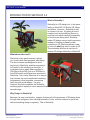
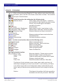
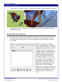
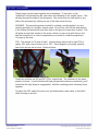
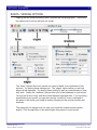
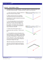
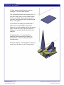
Multimedia Module
SKETCHUP 3.0
USER MANUAL
For information and permission to use these training modules please contact:
Limell Lawson - [email protected] - 520.621.6576
or
Joe Brabant - [email protected] - 520.621.9490
modules available online at http://mll.arizona.edu/workshops.shtml?tutorialpdfs
SketchUp.indd
last modified 6 - 30 - 2003
SKETCHUP 3: User Manual
3
TABLE OF CONTENTS
Introduction to SketchUp………………………………………………….. 4
Basics-Toolbar……………………………………………………….…….. 5
Basics-Navigation…………………………………………………………. 6
Advanced Navigation……………………………………………………... 7
Basics- Viewing Options………………………………………………….. 9
Basics-Pencil……………………………………………………………….10
Basics-Geometry………………………………………………………….. 11
Basics-Push/Pull……………………………………………………………13
Adapting a Model / Folding………………………………………………..14
Components and Groups………………………………………………….16
Move, Rotate, and Arrays………………………………………………….17
Inference Locking…………………………………………………………..18
Entering Dimensions………………………………………………………19
An Advanced Model / Criterion Test……………………………………..20
SketchUp.indd
last modified 7/4/2003
Copyright Arizona Board of Regents, 2003
University of Arizona
SKETCHUP 3: User Manual
4
INTRODUCTION TO SKETCHUP 3.0
What is SketchUp?
SketchUp is a 3D design tool, in the same
family as AutoCAD, 3D Studio VIZ, Maya,
and others. However, SketchUp is also
in a class of its own. By taking a host of
complex tools and simplifying them to a
very few tools which respond contextually
to how they are being used, SketchUp
makes 3D design a more intuitive process.
Instead of focusing on how to make
something in 3D, Sketchup allows a user
to focus on what they want to make in 3D.
This workshop will show a user how to
achieve 3D design efficiently in SketchUP.
What about other tools?
SketchUp is also great because it allows
you to work with other programs effortlessly.
The above house was designed in about
two hours in SketchUp, and then exported to
Art*Lantis for the rendering on the right. It
could have just as easily been exported to
3DS Max or AutoCAD, just as a 3DS Max or
AutoCAD model could have been exported to
SketchUp. Part of why SketchUp is so easy is
that it leaves the more complicated rendering
techniques to other programs, concerning
itself only with actual design. You may,
however, find that sometimes the SketchUp
rendering style is equally or more attractive than the traditional “ray-traced” look of the
second image.
Why Design in SketchUp?
Because it is easy, and intuitive. Imagine if almost all of the processes of 3D design done
through other programs, often utilizing hundreds of tools, could be reduced to just a few,
without sacrificing design complexity. This is SketchUp.
SketchUp.indd
last modified 7/4/2003
Copyright Arizona Board of Regents, 2003
University of Arizona
SKETCHUP 3: User Manual
5
BASICS - TOOLBAR
After you have launched SketchUp 3.0, there will be a main view of an empty
document, and on the left of the screen, there will be a toolbar. This toolbar is
the topic of the first lesson.
In the first section, the toolbar has the following tools:
Selection Arrow:
Select edges, faces, and objects. A selection box drawn left to right selects only what is inside the box, a box drawn right to left selects everything it touches.
Axes:
Move the axes.
Paintbucket / Eyedropper: Apply texture or color / copy texture or color
Erase / Hide / Soften:
Remove lines / Hide lines / smooth a surface.
Measuring Tape:
Measure distances and leave construction
points.
Protractor:
Measure angles and leave construction lines.
Text:
Add notation text.
Dimensioning:
Add smart dimension notations.
In the second section, there are the following tools:
Rectangle:
Make a rectangular plane.
Pencil:
Mother of all tools. More on this later.
Circle: Make a circular plane.
Arc:
Draw a semicircle’s edge.
Polygon:
Draw a polygonal plane.
Squiggle:
Draw a freehand line.
In the third section:
Move / Copy:
Rotate / Copy:
Offset:
Scale:
Push / Pull:
Move any object(s) / Create copies or arrays.
Rotate an object / create a circular array.
Create a scaled copy of a plane within a plane.
Enlarge or shrink an object.
Almost the mother of all tools. More later.
The final set of tools includes zooms, rotates, pans, walks, and turns, all
which help to navigate your view of your model. If you’re smart, you’ll have
a two button mouse with a scroll wheel and a button underneath the scroll
wheel, and you’ll almost never need the last set of tools, except for the last
one:
Section:
SketchUp.indd
last modified 7/4/2003
Third place in the mother of all tools competition, the section tool will rock your world. More later.
Copyright Arizona Board of Regents, 2003
University of Arizona
SKETCHUP 3: User Manual
6
BASICS - NAVIGATION
If you’re familiar with other 3D design programs, you would expect to be able to
see your model from several different angles at once. This is because most other
programs require multiple orthographic (flat, non perspective rendering) views to be
able to align objects correctly. This is not the case with SketchUp, and hence, there
is only one viewing window.
That being said, it is essential to be able to navigate your model quickly and
accurately in order to be able to edit and understand your design. This achieved
through three operations: pan, orbit, and zoom.
1. Open the tutorial folder, and open the “Box House” file. This is a pre-designed
model which will help you to understand the navigation tools.
2. If you have a three button mouse, follow the steps below. If you do not, read the
steps which are written in italics.
3. Try zooming. Roll the wheel forward to zoom in, backward to zoom out. Your
arrow must be placed on an object for accurate zooming, so if you get unpredictable
results, make sure your arrow is over an object in the scene. When you have
finished, press the zoom extents tool (third from bottom, right row).
Try zooming. The plain magnifying glass on the toolbar is the zoom tool. Click, and
move the mouse up to zoom in, down to zoom out. Your magnifying glass must be
placed on an object for accurate zooming, so if you get unpredictable results, make
sure your tool is over an object in the scene. When you have finished, press the
zoom extents tool (third from bottom, right row).
4. Try orbiting. Click the wheel button down, and then use the mouse to rotate
around the model.
Try orbiting. Click the orbit tool (first tool in the bottom set.) Click, and move the
mouse to rotate your view of the model.
5. Try panning. Click the mouse wheel button, and then hold the shift key, and then
move the mouse to pan.
Try panning. Click the hand tool, and then move the mouse to pan.
SketchUp.indd
last modified 7/4/2003
Copyright Arizona Board of Regents, 2003
University of Arizona
SKETCHUP 3: User Manual
7
If you think you’ve got the hang of navigating the model, try finding these three views:
If you ever get lost or cannot find the model, press the zoom extents button to put
things back in view.
ADVANCED NAVIGATION
Although you can achieve almost any view you will need by utilizing the orbit, pan,
and zoom tools, there are far more tools for navigation to further facilitate viewing
your model.
PAGES: In the bottom right of the SketchUp application, you will see a “Pages”
window. This window contains a list of “saved” views. This window has a number of
buttons across the bottom. The plus
sign adds the current view to the list
of pages. The minus sign deletes
the selected view. The rotated arrow
refreshes the status of active view
to what is being currently viewed.
The up arrow moves the order of
the selected page one up, and the
down arrow does the opposite. The
arrow button makes the selected
page active. The final button, the
right facing triangle, brings up the
properties of the selected page,
allowing you to change its name and
decide on what properties (shadows,
shading, section planes, etc.) are
retained when you switch to that
view.
SketchUp.indd
last modified 7/4/2003
Copyright Arizona Board of Regents, 2003
University of Arizona
SKETCHUP 3: User Manual
8
These pages can be linked together into a slideshow. To view this, try the
“slideshow” tutorial sketchup file, and select the slideshow in the “pages” menu. This
will play through the slides in the document. Also notice that you can switch to any
slide in the document by clicking on one of the tabs across the top.
WALKING: The second important method for viewing a model applies if you are
creating an object of a realistic, human scale. At any time, click on the small person
in the toolbar (far bottom left) and then click on the ground or any other surface. This
will place an eye level camera in the scene, which you can move with the eye tool
and the footprint tool in order to experience your model at a realistic perspective.
You may try this now.
FOV: This stands for “Frame of View.” Human beings have a left to right FOV of
nearly 180º, and a top to bottom fov of 120º. These degrees, put simply, quantify
how much we can see at once. Observe below.
These two pictures use 45º and 90º FOVs, respectively. The camera is in the same
position for each. If you’re familiar with how perspective views are constructed, you’ll
notice that the right image is exaggerated, with the vanishing points extremely close
together.
To adjust the FOV, select the zoom tool, and either enter a new value, or hold shift
while zooming in and out.
SketchUp.indd
last modified 7/4/2003
Copyright Arizona Board of Regents, 2003
University of Arizona
SKETCHUP 3: User Manual
9
BASICS - VIEWING OPTIONS
Keeping the box house document open, consider the following graphic. There are a
few options as to how we will view our model.
The “faces” options allow us to decide on a level of detail, from wireframe to fully
textured. Try altering these settings now. The “edges” options allow you set how
edges will be displayed. Try altering these settings to gain an understanding of how
they work. Finally, the “shadows” options allow you to cast shadows on your model.
You may set a time of day, and the contrast between light and dark. If you are being
specific about your model, you can also use the “model info” menu command to
set where in the world your model is located, allowing for the most accurately cast
shadows.
The angles do not change how you view your model but contain preset camera
angles. Click through them to see what angles they present of your model.
SketchUp.indd
last modified 7/4/2003
Copyright Arizona Board of Regents, 2003
University of Arizona
SKETCHUP 3: User Manual
10
BASICS - THE PENCIL TOOL
The pencil tool is THE SketchUp tool. It may seem simple or unexciting at first, but it
has nearly infinite potential. To begin this lesson, create a new document.
1. In the new document, rotate the camera so
that all the axes are clearly visible.
2. Make sure the pencil tool is selected,
notice that a text area in the bottom left is
prompting you to select a start point, and click
once in the window.
3. You will notice there is now a line with a
start point, with the other end attached to
your cursor. As you move your pencil, the
line “snaps” to the three colors of the axes,
indicating you are drawing a line parallel to
the colored axes indicated.
4. Draw in the red and green axes, to
produce two lines, as shown. Click to end a
line.
5. For the third line, return in the red axis to
make a third line of a rectangle. To accurately
form the rectangle, press the shift button while
your line is in the red axis. This will lock the
current “inference,” (more on this later) and
you may move your pencil to the initial point,
creating the image to the right.
What we have done is locked the line in the
red axis, and lined its length up with a point
along the green axis, marked by the dashed
line.
SketchUp.indd
last modified 7/4/2003
Copyright Arizona Board of Regents, 2003
University of Arizona
SKETCHUP 3: User Manual
11
6. Now, draw the fourth line to close the
rectangle. This will create a plane.
This is the basic function of the pencil tool. A
few more steps, and you can create shapes
like the one below. Try drawing a shape of
your own, using the blue axis to draw vertical
lines. A few points:
If your line is not ending on another line or
plane, and it is not locked to any axis or
inference, you will probably put it in the wrong
place. A line can “look” right, but without a
reference, it can be hard to tell where it will
really be.
Try deleting lines. To understand how
sketchup closes planes along edges, try
deleting lines to see how shapes can be
deconstructed.
Move the camera. It is important to view your
model from all sides; it is a 3D composition.
SketchUp.indd
last modified 7/4/2003
Copyright Arizona Board of Regents, 2003
University of Arizona
SKETCHUP 3: User Manual
12
BASICS - GEOMETRY
Although the pencil tool is the most versatile drawing tool, it can also be the most
time consuming. Often times you will use the other drawing tools to create simpler
shapes more quickly.
Freehand
Arc
Circle
Rectangle
Polygon
Creating the box, circle, or polygon is simple: select the tool, click once, drag out the
size, and click again. The arc is created with two endpoints and a “bulge” distance,
and the freehand shape is exactly that: just start drawing a freehand line. Try all of
the shapes at least once, and try drawing one shape completely inside of another
shape as well.
Also, take this time to try the offset tool. Click on one of the planes you have created,
and then click on the offset tool in the toolbar. Return and click on the plane again,
and you will see the offset tool creates a proportionally identical shape, which may be
placed around or inside the original shape.
Finally, try the scale tool. Click on a plane, and then select the scale tool. You will
see handles appear around the shape. Use these handles to resize it. You may also
resize shapes, or groups of shapes, and not just planes.
SketchUp.indd
last modified 7/4/2003
Copyright Arizona Board of Regents, 2003
University of Arizona
SKETCHUP 3: User Manual
13
BASICS - PUSH / PULL
Push / Pull is similar to an extrude command in other 3D design software, but it is far
more adaptive and much easier to use.
1. Draw a rectangle using the rectangle tool.
2. Select the push / pull tool, and highlight the rectangle plane.
3. Click, and “pull” upwards to create a
box.
4. Now, select the pencil tool. Move the
cursor along one of the box’s top edges,
until it pauses on a cyan point, indicating
the midpoint.
5. Click, and draw a vertical line down
the box to the bottom edge.
6. Now, “push” one of the halves backwards, and the box will become a “L”
shape.
7. Finally, draw a small rectangle on one
of the box’s vertical planes, and use
the “pull” motion to create an extension
inside of the plane.
Your box should look something like the
box that has been rendered to the right.
SketchUp.indd
last modified 7/4/2003
Copyright Arizona Board of Regents, 2003
University of Arizona
SKETCHUP 3: User Manual
14
ADAPTING A MODEL / FOLDING
Let’s take the model we’ve just created in the last
exercise, and make some changes to it.
1. Make the last rectangle, the one that sticks out
of the “L,” flatter, and lower to the ground, using
push / pull.
2. Using the arc tool, click once on each endpoint
as shown to the right, and then bulge the circle until it says “half circle.” Click again. You will notice
that it is now a plane, attached to the end of the L.
Also note that the line dividing the two shapes is
thin, not a thick black. This means the two shapes
are attached.
3. Use push / pull to extend the semicircle to the
ground. Note that it will automatically pause at the
end of the other shape. Push / pull will always do
this, to help you line up attached shapes.
4. Draw a line, lengthwise, down the center of
the rectangle that is sticking out, as shown in the
fourth frame to the right. Create another line in exactly the same way, on the underside of the rectangle. What we are doing is creating a “fold” line.
SketchUp.indd
last modified 7/4/2003
Copyright Arizona Board of Regents, 2003
University of Arizona
SKETCHUP 3: User Manual
15
5. Now, observe the fifth frame. Our rectangle
has become a canopy. Select the move tool, and
move your cursor over the middle line in the rectangle. The line should turn yellow. Now, click on
the line and move the cursor upwards, until the
move locks into the blue axis, just like it would
when using the pencil tool. You will see the rectangle “fold” into the triangular shape. Do the same
for the line underneath the rectangle, and you
should see a shape like the right one.
6. Now draw a line to the ground, from the corner
of the canopy. You can line up the vertical with the
bottom of the building, like you did when you drew
the rectangle. From the bottom of the line, draw
a small square with the rectangle tool. Then, use
the push pull to extend it to the lowest point of the
canopy.
7. In the next image, you will see that the inside
top line of the column we have created is being
moved in the blue axis to match the edge of the
canopy. Try doing this. It should automatically
lock the canopy when you move it close. If you
like, try duplicating the column on the other side.
8. You are surprisingly close to the last image.
With just a few more skills, you should be able to
produce even better models in very short time.
SketchUp.indd
last modified 7/4/2003
Copyright Arizona Board of Regents, 2003
University of Arizona
SKETCHUP 3: User Manual
16
COMPONENTS AND GROUPS
If you’ve used computers much at all, you should be familiar with what a group is. A
group in SketchUp acts like you would expect: it takes a grouping of separate elements and connects them into a whole.
Consider the pictures above. In the first, the shape is ungrouped. It is a set of edges
and planes, related but selected separately. In the second, the selection is grouped.
Now, all these elements are a single set, and treated as such. They are moved together, and are not immediately editable. In the third frame, we see that the objects
around the grouped set are grayed out. This means that the group is being edited.
By double-clicking on any group, you can edit it’s elements as though they have not
been grouped. Click outside of a group to close it.
Components work exactly the same as groups, with one major change. When you
select a group of objects, right click them, and choose “make component,” this group
becomes an instance. A component, or instance, is essentially a single, created
many times. If you have 30 copies of one component, you may edit all of these objects simultaneously by editing one of them. We’ll explore this in a moment.
The other use of a component is to divide a complex model into
many parts. Consider the model to the left. Rather than try to edit
a part of the whole model while the other parts remain in the way,
we may make a component, and edit that single part as a separate
file. The second image shows us how editing just one piece can
cut down on complexity and ease the modeling process.
SketchUp.indd
last modified 7/4/2003
Copyright Arizona Board of Regents, 2003
University of Arizona
SKETCHUP 3: User Manual
17
MOVE, ROTATE, AND ARRAYS
Instructor: Go over the introduction to this lesson, and then demonstrate all the steps
of the exercise before asking the students to try.
1
2
3
4
The move tool can move whole objects, or move single elements in ways that deform
the whole, much in the way we created the canopy in the previous exercise. The
other function of the move tool is the “move a copy,” which can also be used to create an array.
1. Open the tutorial file called “move and rotate.” You will see the object in
fig.1, a component.
2. From the angle shown in figure one, click on the far bottom left corner of
the object with your move tool, while holding the option button. Holding option tell SketchUp that you will be moving a copy. Then, with the new object,
click on the bottom right hand corner of the same object, directly across the
original point in the green axis, and the new object will be placed. It should
look like fig. 2.
3. Now, click on the midpoint along the bottom edge of either object with the
option key held down, and create the object seen in fig. 3.
4. Using the arrow tool, select all three objects at once. Then, select the rotate tool. Move your cursor to the intersection along the bottom of the figure,
(shown as a red highlight in fig. 3.) and let it snap on the point. Then, back
your cursor away, in the red axis, so that you are just a short ways away from
the point. Then, while holding option, click, and rotate 90º, and click again.
Now, type “3x” on your keyboard. Instead of creating one copy, you have created 3 copies. Your screen should look like fig. 4.
5
5. Now, double click (with the arrow
tool) any of the objects. As you make
changes within the component, you
will see that all the shapes react in the
same way. Experiment with changes
you can achieve.
SketchUp.indd
last modified 7/4/2003
Copyright Arizona Board of Regents, 2003
University of Arizona
SKETCHUP 3: User Manual
18
INFERENCE LOCKING
Instructor: Go over the introduction to this lesson, and then demonstrate all the steps
of the exercise before asking the students to try.
We’ve used inferencing before, but this lesson will describe it in more detail, and
utilize more advanced inference locking techniques. An inference is an automatic response by SketchUp into what you may be planning to draw, enabling you to quickly
form complex shapes. It is based on either axial or previously drawn geometry. A
basic example of inference locking is when we used the pencil to draw a rectangle.
Notice the image to the left. As we drew the one line
in the red axis, SketchUp inferred the line’s connection to the point across the rectangle, in the green
axis. It drew a green dotted line to indicate this inference. This is the simplest form of inferencing.
1. We want to draw a part of a triangle, with line C.
We want the endpoint of line C to be aligned with the
end of line B, and the midpoint of line A. So we first
start the line, and then move our cursor over line A
until Sketchup locks on to a cyan dot, the midpoint.
Then, we back the cursor away, in the red axis, and
then press shift when we see a red dotted line. This
locks the inference in the red axis. Then, we move
our cursor over the endpoint of Line B, and we will
see the image to the left. Now click.
2. Now, instead of making the triangle, let’s draw a
line parallel to line C from the midpoint of line A. To
do this, first click on the midpoint of line A with the
pencil tool. Then, pass the pencil cursor over line C.
You may want to “stroke” along the line for a moment,
and then move your cursor away. As you bring your
cursor away, try to draw a parallel line. As you get
close to the right direction, the line will turn pink and
say “Parallel to Edge.” Hold shift to lock the inference, and then line up with Line C as shown to the
left.
SketchUp.indd
last modified 7/4/2003
Copyright Arizona Board of Regents, 2003
University of Arizona
SKETCHUP 3: User Manual
19
3. You can also infer using the measuring tape tool.
Here, we’ve created a small box with a roof. We want
to produce the same slope of the roof on the plane
we created in the last exercise. Select the measuring
tape, and click along the line of the roof. Then, move
your cursor over the endpoint of the original plane.
This creates a construction line parallel to the slope of
the roof. Then, you can use the pencil tool to draw a
line along the construction line. Try this now.
4. You may also use inferencing when push/pulling
also. Simply begin the push/pull, and then pass your
cursor over a plane, edge, or point, and you will see
a dashed line representing the inference. Then click
again to end the push/pull. Try this now.
ENTERING DIMENSIONS
Instructor: Go over the introduction to this lesson, and then demonstrate all the steps
of the exercise before asking the students to try.
Any object you draw can be given accurate dimensions. When you are drawing a
line, press tab, and enter a value, such as 10’. This will create a line 10’ long in the
direction you were drawing. For a rectangle, enter 10’,10’. This will create a 10 x 10
square. You may also use dimension commands using push/pull, move, and angle
values when rotating. You’ll see the values that you are entering in the text box in the
bottom right of the window.
Try creating a few dimensioned objects before continuing.
SketchUp.indd
last modified 7/4/2003
Copyright Arizona Board of Regents, 2003
University of Arizona
SKETCHUP 3: User Manual
20
AN ADVANCED MODEL / CRITERION TEST
Instructor: Go over the introduction to this lesson, and then demonstrate all the
steps of the exercise before asking the students to try. This is the most complicated
exercise in the module, so keep in mind your demonstration will carry more weight
than the instructions. Be sure to help students through the process after the
demonstration.
We’ll be creating one model in this last exercise, although it will be the most complicated. It will utilize previously learned techniques, as well as introduce new ones.
Keep in mind the undo command, (apple key + Z) as it will correct seemingly large
mistakes instantly, even those of several steps back, according to how many times
you use the command.
1. Create the rectangle to the left, 30’ x
30’. Then use the offset tool to offset the
plane inwards 2’. Then, push/pull the inside
rectangle downwards 2’, as shown. Finally,
color the planes shown brown, using the
paintbucket tool. Simply click the paintbucket tool, select a color from the palette which
pops up, and click on the planes you wish to
color.
2. Create this cone shape. Create a 10’ radius circle on the ground away from the rectangle we created. Then, use the offset to
create an interior circle, offset by 2’. Then,
select the move tool, and place it over the
inside circle, press the command button, and
click once. Continuing to hold the command
button, move up in the blue axis 2’, and click
again. Color accordingly, select the whole
object, and make it into a group.
3. This may seem complicated, but it is not.
Using a diagonal drawn across the bottom
of the rectangle, corner to corner, and a line
drawn inside the grouped circle across it’s
center, use the move tool to center the cone
inside the rectangle, it’s top level with the
rectangle’s top, as shown. Then, create two
bridges, connected to points along the circle,
with the pencil and push/pull tool, as shown
in the picture. Color as shown.
SketchUp.indd
last modified 7/4/2003
Copyright Arizona Board of Regents, 2003
University of Arizona
SKETCHUP 3: User Manual
21
4. Confused about scale? Using the window menu to open the components window,
select a person from the components window, and drag him/her into the scene. Then,
try using the offset tool, the push/pull tool,
and the move tool to create the three small
walls as shown.
5. Now use the component menu again,
and add two trees and a bench. If the objects seem to “thick” with black lines, use the
eraser tool, with the shift key held down, to
hide the lines. Make sure you are editing
inside the component before hiding the lines.
Try clicking on the shadows and seeing how
it looks.
6. Try creating a water feature like the one
shown; don’t worry too much about precision. The challenge here is to be able to
replicate a shape using only your own understanding of the program.
Instructor: although step six can be a fairly
difficult one, most students should be able
to accomplish it if they have understood the
module up to this point. Consider this step
as the criterion test- do not do the work for
them.
SketchUp.indd
last modified 7/4/2003
Copyright Arizona Board of Regents, 2003
University of Arizona