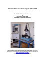
1
Emulsion Plate Creation Using the Mann 3000
For the Micro-Electronics Laboratory
At
University of Notre Dame
Department of Electrical Engineering
This user manual is not be removed from the Mask Making Room. This includes
making copies. A downloaded copy can be obtained from the web at the following link:
http://www.nd.edu/~ee/ndnf/
or contact Keith Darr for a copy of this manual.
Purpose
The Mann 3000 is a computer controlled lithographic pattern generator used to
generate master emulsion plates. These patterned emulsion plates are used to create
photomasks for use in the photolithography for integrated circuits.
Reference Documents
Procedural documents written by Tatyana Orlova
Additional Equipment Required
None
Materials Required
Emulsion coated plate 5” X 5” (127 X 127 mm)
PD-86 Photomask Negative Developer
PF-95 Photomask Fixer
3.5” Floppy disk
100 Mega byte Zip disk
Protective Equipment Required
Safety glasses
Latex Gloves
Engineering and/or Administrative Controls
Only authorized users may operate this piece of equipment
Training
To obtain training on this machine, please contact Keith Darr (office 221 Cushing,
phone 1-5497, email [email protected])
Problems
For problems, clarification of procedures, or general information pertaining to this
machine please contact one of the following personnel.
Keith Darr 631-5497
[email protected]
Mike Thomas 631-7493
[email protected]
Mark Richmond 631-6478 [email protected]
In Case of Emergency, Please Contact Notre Dame Security at
911
MSDS’s can be located in the EE Department office or in Room 244 near the door.
Keith S. Darr
Rev 2.1
11/3/2008
2
Table of Contents
Page
4-5
6
7 - 12
12
12
13-15
Keith S. Darr
Rev 2.1
11/3/2008
Contents
Authorized Users
Setup
Operation
Developing
Completing Operations
Appendix
3
Authorized Users List
Name
Jie Wu
Zach Gagnon
Diana Hou
Jeffery Bean
Kai Sun
Di Liang
Wei He
Lili Ji
Yong Tang
Niti Goel
Ying Cao
Ning Su
Jon Valenzuela
Qing Liu
Ni Man
Zhuowen Sun
Jie Su
Zengiao Jin
Sangeetha Swaminathan
Jon Baeten
Bo Gao
Jing Zhou
Mike Coogan
Chuanxin Lian
Vlad Protasenleo
David Deen
Wentao Luo
Adams Tong
Siddharth Maheshwari
Qinxin Zhang
Juan Jiang
Aaron Prager
Heng Yang
Loukas Tsagalas
Chris Seibert
Tom Zimmerman
Jia Guo
Keith S. Darr
Rev 2.1
11/3/2008
Email
[email protected]
[email protected]
[email protected]
[email protected]
[email protected]
[email protected]
[email protected]
[email protected]
[email protected]
[email protected]
[email protected]
[email protected]
[email protected]
[email protected]
[email protected]
[email protected]
[email protected]
[email protected]
[email protected]
[email protected]
[email protected]
[email protected]
[email protected]
[email protected]
[email protected]
[email protected]
[email protected]
[email protected]
[email protected]
[email protected]
[email protected]
[email protected]
[email protected]
[email protected]
[email protected]
[email protected]
[email protected]
Advisor
Chang
Chang
Chang
Porod
Merz
Hall
Lieberman
Porod
Fay
Jena
Hall
Fay
Xing
Bernstein
Fay
Fay
Bernstein
Snider
Wu
Wu
Lieberman
Xing
Chang
Xing
Ken Kuno
Xing
Chang
Snider
Chang
McGiun
A.E. Miller
Snider
Bernstein
D.A. Hill
Hall
Xing
Liu
Date
04/29/04
05/27/04
05/27/04
06/3/04
07/26/04
07/26/04
10/05/04
10/08/04
10/08/04
10/22/04
12/14/04
12/20/04
02/23/05
03/16/05
02/28/05
04/11/05
04/14/05
04/18/05
06/15/05
06/15/05
06/17/05
07/19/05
08/12/05
9/16/05
9/9/05
10/18/05
10/24/05
10/24/05
10/25/05
10/25/05
10/25/05
10/25/05
4/18/06
06/08/06
8/14/06
12/11/06
12/21/06
4
Authorized Users List
Name
Peter Hoffman
Zhen Wang
Paul Robbins
Preshant Deshlahra
Kejia Wang
Jason Kulick
Yu Cao
Gilad Yossifon
Xinguong Cheng
Sagnik Basuray
Nishant Chetwani
Dane Wheeler
Nan Sun
Chao Sun
Ireneusz Janik
Marya Lieberman
Amol Singh
Lisa Cole
Xiu Xing
Joe Bonath
Kristen Anderson
Andy Carter
Connor Griffith
Hubert George
Yu-chen Chang
Prasad Sarangapasei
Yunshan Wang
Dan Ho
Qingling Hang
Qin Zhang
Keith S. Darr
Rev 2.1
11/3/2008
Email
[email protected]
[email protected]
[email protected]
[email protected]
[email protected]
[email protected]
[email protected]
[email protected]
[email protected]
[email protected]
[email protected]
[email protected]
[email protected]
[email protected]
[email protected]
[email protected]
[email protected]
[email protected]
[email protected]
[email protected]
[email protected]
[email protected]
[email protected]
[email protected]
[email protected]
[email protected]
[email protected]
[email protected]
[email protected]
[email protected]
Advisor
Zhu
Bohn
Berstein
Bernstein
Jena
Bernstein
Jena
Chang
Chang
Chang
Chang
Seibaugh
Ruggiero
Jena
Ian
Lieberman
Jena
Roeder
Fay
Bernstien
Bernstien
Bernstein
Porod
Snider
Chang
Zhu
Chang
Xhu
Jena
Seabaugh
Date
3/22/07
4/11/07
6/25/07
6/25/07
07/17/07
08/17/07
09/05/07
10/08/07
10/08/07
10/08/07
10/08/07
10/23/07
12/19/07
4/14/08
04/30/08
05/14/08
05/21/08
06/18/08
06/18/08
06/23/08
06/23/08
06/31/08
07/01/08
07/16/08
07/25/08
08/21/08
07/25/08
09/12/08
10/07/08
10/29/08
5
Setup
Note: Prior to mask creation, a plastic mask case for storing the reticle may be obtained
from the lab staff.
1. Turn on the red light outside of the reticle room to indicate that the room is in
use.
2. Set up the mask developing chemicals:
a. The baths, which are located on the wet bench, are used to immerse
the mask during the developing process. The solution contents are
clearly labeled on each container lid. Be certain to not interchange the
lids. Doing so will cause cross contamination of the solutions.
b. Each developing bath should have a solution level of approximately
½” (1.25 cm)
c. If the solutions in the baths are older than 3 days, they should be
discarded and replaced with clean, fresh chemicals
i. Empty developing baths in the wet bench sink.
1. Clean, fresh chemicals are in the lower right hand side
of the reticle room wet bench.
a. If this supply is empty, a new bottle may be
obtained from the yellow chemical cabinet near
the reticle room door.
b. The bottles are dated. Use oldest dated bottle.
Empty bottles or bottles dated greater than one
year are to be discarded as per the laboratory
safety manual.
Note: The janitor will not empty the trash container located
inside of the reticle room. If the trash is full, it is the
responsibility of the lab user to exchange the container
with the container located outside of the reticle room.
ii. Replenish each bath at level of approximately 1/2” (1.25 cm)
iii. In the logbook, record the exchange of solution.
3. Retrieve a box of emulsion plates from the yellow cabinet and place it on the
table located in the printing room.
a. The supply of emulsion plates is located on the left hand side of the
cabinet. These containers are dated, use the oldest dated container.
This one will likely have the tape removed from around the lid.
\
Keith S. Darr
Rev 2.1
11/3/2008
6
Operation
1. If the Mann 3000 PC is off, turn on the power to the PC
a. The system will automatically boot into the pattern generator software
2. If the Mann 3000 PC is ON and at the DOS prompt
a. Type PGEN and press Enter
3. If the emulsion plate is to be used to create a Stepper Mask (GCA 6300)
a. Measure the plate dimensions and calculate the error as the
difference between the measured dimensions and an ideal plate
which would be 127mm.
b. Take 2.5mm – (error/2) = offset
c. Manually adjust the y-coordinate of the stage to offset before
powering on the stage drivers.
4. If the emulsion plate is to be used to create a Contact Printer Mask (Karl
Suss)
a. Ensure that the y-coordinate of the stage is at 0.0 mm before
powering on the stage drivers.
4. The Mann 3000 software will prompt the operator with the steps of operation.
a. The first prompt is :
“Enable main power and XYWHA chassis power ONLY!!
Manually move X-Y staging to the ORIGIN position
Press any key when done”
i. The main power is the switch hidden directly below the shelf
that the computer monitor and the keyboard sits. This switch
should be on already, if it isn’t, turn it on. (Figure 2)
ii. The stage should be at (0, 0) or (0, 2.5) depending on your
process, however, you should verify its position. If it is not,
then manually position the stage by rotating the stage position
dials. (Figure 1)
1. The stage position is read on the linear gauges mounted
on the right hand side of the stage.
2. Fine positioning increments are read on the micrometer
dials.
iii. The XYWHA chassis power is the right most switch on the
XYWHA chassis. Turn this switch on only.
Note: Do not turn on the X, Y, W, H and A switches at
this time. (Figure 2)
iv. Once these steps are complete, press “any key.”
1. Do Not use the Arrow Keys, this will cause an error.
Keith S. Darr
Rev 2.1
11/3/2008
7
b. On the right side of the software screen, ensure that all current
positions, destinations, and velocities read 0. If there is any number
other than 0 in this step, then the fuse is bad.
i. Turn off the chassis power and replace the fuse. Reboot the
computer using Cntl+Alt+Del. Restart the procedures.
c. The second prompt instructs the operator to:
“Enable each X, Y, W, H, and A motor
Enable the flash unit
Press any key when done”
i. Switch the X, Y, H, W and A switches to the up position.
ii. The power switch for the flash unit is the right most switch.
This is a two-position switch. Make sure to position it
completely up. The light will turn on.
Note: Verify that the switch on the left hand side (AUTO/
MANUAL) is in the auto position.
iii. Once these steps are complete, press “any key”
1. Do not use the Arrow Keys. This will cause an error.
2. The machine will automatically move the stage to the
load position
a. If you set the origin to be (0,2.5) the stage will
move to (100, 102.5)
b. There will be a small error at the load position,
this is normal. The machine will work correctly
and will create an accurate emulsion plate
Note: If the stage reaches a limit condition, one
of two red lights on the left side the
stage will be illuminated. Contact lab
staff.
Note: Do not attempt to move the stages
manually, by turning the stage
micrometers, from this point on. Doing
so, may cause damage to the equipment.
3. The help menu will appear on the screen
a. The help menu contains a list of the commands
available for use in the Mann3000 program. It
is able to be redisplayed by pressing “H.”
Keith S. Darr
Rev 2.1
11/3/2008
8
5. Press the letter “O” to move the stage from the load position to the origin.
Once this movement has completed, press “L” to return the stage to the load
position. Perform this cycle 3 to 5 times.
a. This will cause the lubricant on the Mann 3000 to spread evenly.
i. Verify that the stage is moving to the correct position.
1. On the right hand side of the computer screen is a
readout of the destination (xdes or ydes) and current
(xcur or ycur) position.
2. If there is an error where the stage does not move to the
correct location: for example, the reading on the
computer indicates the stage is at (0,0) and the stage is
actually at (50,0), or if a limit light is turned on, contact
lab staff. The fuse is likely bad. Power down the
system, change the fuse, and restart the procedure if
trained.
b. Finish the cycle with the stage in the load position.
6. Insert your 3.5” disk into the floppy drive
a. If you are uncertain of your file name:
i. Type “S” to cause the program to shell to DOS.
1. Press “Y” to continue
ii. Type “a:” and press “Enter.”
iii. Type “dir” and press “Enter” to display a directory of the A:
drive.
iv. Record the name of the file that you desire to use.
v. Type “exit” and press “Enter” to return to the Mann 3000
program.
b. If you know the name of your file:
i. Type “F”
ii. When Filename: appears, type the path and the name of your
file with the “.dwm” extension
1. Make sure you specify a:
2. For example: Filename: a:test.dwm
iii. Press “Enter”
1. At the bottom of the PC screen the Mann 3000 program
will return “Data file : your file name” to indicate that
the file has been loaded.
7. Press “E”
a. This will verify the file syntax, report potential errors, and indicate the
number of exposure counts.
i. If there is a number of syntax errors, the disc may be bad or
you may need to redo the file conversion process.
Keith S. Darr
Rev 2.1
11/3/2008
9
8. If you are making an emulsion plate for use on the GCA-3696 (contact mask)
(stepper masks do not require this step):
a. Type “<CTRL>-F”
i. Hold the control button and type F.
b. At the prompt “Fiducial Type [A,B,C]:” Type “A”
i. This will cause the Mann 3000 to print the necessary alignment
marks on the emulsion plate for alignment on the GCA-3696.
9. If a title is desired
a. Press “T”
i. Select Left
ii. Choose 2.02 mm high
iii. Include 1mm offset
10. Turn off all lights in the mask making rooms, except for the red lights.
11. Retrieve the plate holder from the cabinet that is to the left of the door.
12. Rotate the lock, on the back of the plate holder, counterclockwise to allow
removal of the back of the plate holder.
a. Load the emulsion plate into the plate holder with the emulsion side
face down. The emulsion will be facing up when mounted when the
plate holder is mounted on the Mann3000’s stage.
Note: The emulsion plate’s box has a sticker on the front lower
part to indicate the side of the plates that have the
emulsion chemical. Handle the emulsion plate by the
edges. Make sure not to touch the emulsion plate face, as
this will cause defects on the emulsion plate.
i. There are three small dots on the inside of the plate holder, two
on one side, and one on another. (Figure 5) Pick the plate
holder up and slightly tilt it so that the emulsion plate is aligned
against the two dotted sides of the plate holder.
Keith S. Darr
Rev 2.1
11/3/2008
10
13. Reinstall the back of the plate holder. Make sure the plate stays aligned.
a. Apply a slight amount of pressure downward and lock the back of the
plate holder in place. The plate holder back has spring-loaded pins
that will apply pressure to the plate when installed.
b. The lock should be perpendicular to the frame if properly locked.
c. Turn the plate holder over so the emulsion plate is face up and bring it
over to the Mann 3000.
d. While the holding the fasteners lifted up slightly, carefully slide the
plate holder into position on the stage under the optical column.
i. Do not let the fasteners drop while positioning the plate holder.
Doing so may cause damage to the level stage surface.
e. Align the plate holder to the stage alignment pins as per the following
steps:
Note: There are two pins mounted on the rear of the stage.
(Figure 4) On the edge of the plate holder, there are two alignment
plates. One of the alignment plates is flat and the other has an "L"
shape if viewed from the top of the plate holder down. (Figure 5)
f. Slide the plate holder in place so that the "L" plate is against its
associated stage pin. It should be touching the pin both on its flat side
and on its extended side. (Figure 6)
g. Using the "L" side's stage pin as a pivot point, slightly rotate the plate
holder until the flat alignment plate is against the its associated stage
pin. (Figure 7)
h. The stage pins will be touching the plate holder alignment plates at 3
points if the plate holder is correctly aligned; 2 points on the "L" plate
and 1 on the flat plate.
14. While holding pressure on the plate holder and maintaining the correct
alignment position, tighten down the fasteners, finger tight, to attach the plate
holder correctly to the Mann 3000 stage. (Figure 8)
15. The plate it ready for printing. Type P.
a. If you choose, you may type I instead of P to produce a mirror image
pattern. Doing so will rotate the image about the y-axis 180 degrees.
b. The Mann 3000 will begin printing the emulsion plate.
c. When the exposure process is complete, the stage will move to the
load position and the computer will display a message indicating
completion of the exposure.
16. Remove the plate holder by loosing the retaining screws and sliding it out in a
similar fashion as it was inserted. Be certain to lift the fasteners up slightly so
to prevent them from catching on the stage.
a. Be careful to not hit the emulsion plate on the column extending down
or you may cause a scratch on the objectives.
Keith S. Darr
Rev 2.1
11/3/2008
11
17. Bring the plate holder over to the table and turn it over so that the emulsion
plate is facing down. Rotate the lock on the back of the plate holder to unlock
the plate holder back. Carefully remove the emulsion plate from the plate
holder.
a. The side facing up does not have any emulsion on it and will not
scratch if touched slightly. However, try to only touch the outer edge
of the emulsion plate to minimize the number of particles generated on
the plate.
b. Replace the back of the plate holder and lock it in place.
18. Bring your plate to the front room to be developed.
Developing
Note: Slightly agitate the bath solutions during the developing process to ensure a
constant concentration of the solution.
Use Teflon tweezers to remove the plate from the developer solution.
1.
2.
3.
4.
5.
6.
Use PD-86 developer to develop the emulsion plate for 5 min.
Rinse the plate in DI water for 1 min.
Put the plate in fixer PF-95 for 3 min.
Rinse the plate in DI water for 1 min.
Rinse the plate with Methanol.
Place the plate in the slotted Teflon plate holder and let air dry
a. Alternatively, you may blow dry the plate with Nitrogen.
Completing Operations
1. The lights may be changed back to the yellow lights at this point.
2. On the computer Type “O” to cause the Mann 3000 to move to the origin
position. This will position the stage for the next user.
3. Turn off the flash lamp power supply.
4. Disable the X, Y, H, W and A motors and turn off the chassis power for this unit.
5. Exit the Pgen3001 software by pressing “X.”
6. Return the emulsion plate box to the yellow cabinet by the front room door.
7. Clean up the work space
8. Indicate the number of emulsion plates that were used, chemicals changed, or any
other important information in the logbook and log out.
9. If you are finished with the reticle room, turn off the outside red light.
Keith S. Darr
Rev 2.1
11/3/2008
12
Appendix
System Power
Figure 1 Manually setting
stage position
Stage power is the switch on the right
Figure 2
Figure 3
Keith S. Darr
Rev 2.1
11/3/2008
System power and
Stage control
Flash Lamp Power Supply
Power switch is right most
13
Figure 4 Stage alignment pins
Figure 5
Alignment points for the
emulsion plate
Figure 7 Aligning the plate
holder
Keith S. Darr
Rev 2.1
11/3/2008
Figure 6 Aligning the plate
holder
Figure 8
Tightening the plate
holder to the stage
14