1
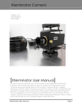
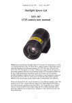
Observer’s Guide for the Martin Observatory
14-inch Telescope
John H. Simonetti
January 25, 2012
1
Introduction
This Guide outlines the basic procedures for running the telescope and collecting
images using its CCD camera. For more advanced use consult the pdf files of
the manuals for TheSky6 and CCDSoft Version 5 available on the computer at
the observatory, and at Software Bisque’s Documentation webpage.
The 14-inch telescope is computer controlled. Virtually the only time you
need to touch the telescope is to flip its on-off switch. Indeed, since the telescope’s accurate pointing ability is sensitive to disturbances, a good rule of
thumb is: Unless this guide specifically instructs you to do so,
do not physically touch the telescope mount, tube,
ccd camera, focuser, cabling, or optics.
This also means you should not try to clean or adjust anything on the telescope,
including the optics. If you follow this rule you will avoid most problems, and
the instrument should give you, and others after you, excellent performance.
If you encounter difficulties, or are unsure of what to do at some stage, don’t
hesitate to contact Dr. Simonetti (phone numbers are posted in the control
building). “Better safe than sorry!”
The 14-inch telescope is a Celestron Schmidt-Cassegrain telescope mounted
on a Paramount ME equatorial mount from Software Bisque (SB). Attached to
the telescope is an ST-8E CCD camera from Santa Barbara Instrument Group
(SBIG), in combination with an SBIG CFW-8A motorized filter wheel. Focusing is done using an Optec TCF-S Focuser. Present in the optical path is an
Optec NextGEN WideField 0.50X telecompressor, which halves the standard
focal length of the telescope, doubling the width of its field of view. The dome is
equipped with hardware from Meridian Controls Corporation. Telescope, camera, and dome control are accomplished using SB’s TheSky, CCDSoft, and AutomaDome software, running on a dual-monitor Windows XP computer. “Flash
drives” can be used for image transport.
1
2
BASIC SYSTEM SPECIFICATIONS
2
2
Basic System Specifications
• Focal length1 : 2.14 (f/6.0)
• CCD format: 1530 x 1020 pixels (unbinned)
• Pixel size: 9 microns x 9 microns, or about 0.87 arcseconds x 0.87 arcseconds (unbinned)
• Field of view: about 22 arcminutes x 15 arcminutes, long axis is oriented
approximately E-W on the sky
• Filters: B, V, and R Bessell broadband photometric filters, 3nm-bandpass
Hα filter, “clear” (no filter)
• Exposure range: 0.11 to 3600 seconds
• CCD linear saturation level: about 16384 counts unbinned (1x1), 65536
at 2x2 and 3x3 binning
3
A Typical Observing Session
This section lists the steps taken during a typical observing night. The order of
the start up and shut down steps is very important. For example, the Paramount
should not be turned on until it’s clear that the PC is on and working and TheSky
software is started and working, otherwise the telescope’s pointing model may
be lost! (A convention used in this guide: a program menu item such as “Save
As” under the “File” menu in a program is written as “File | Save As”.)
3.1
Start Up
You should turn on the stairway lighting at the bottom of the stairs leading up
to the observatory when you arrive; it should be turned off after climbing the
stairs to the deck. You should have the deck lighting on during the start up
and shut down procedures, but you should turn off all outdoor lighting during
observing.
Follow these steps in the order given!
1. In the control building, check for notes on the clipboard near the computer concerning updates to the telescope start up, shut down, or usage
procedures.
2. Gently connect up various connectors, handling the cables and connectors gently and with care, to prolong their lives and ensure good performance. . .
1 The focal length, field of view, and the angular size of pixels have been determined empirically
3
A TYPICAL OBSERVING SESSION
3
(a) Insert power plug “A” into wall socket “A” to the left of the PC
monitors.
(b) Insert power plug “B” into extension cord “B” to the right of the PC
(enables power for all components in the control building).
(c) Connect together the connectors labeled “C” sitting to the right of
the PC (connects the Dome Controller to the PC).
(d) Connect together the connectors labeled “D” sitting to the right of
the PC (connects the Paramount to the PC).
(e) Insert the connector for the yellow cable labeled “E” into the TCF-S
Hand Controller unit sitting to the right of the PC (connects the
TCF-S focuser to the PC).
(f) Insert the connector for orange cable “F” into port “F” on the back
of the 3Com Hub TP16C sitting to the right of the PC (connects
CCD camera to PC).
3. Power up the computer and monitors. Wait for Windows to start up.
Login to the astro account.
4. In the dome, connect up various connectors, handling the cables and connectors gently and with care, to prolong their lives and ensure good performance. . .
(a) Connect together the two serial connectors labeled “A” sitting on the
edge of the dome wall, between the dome rotation motor and the desk
(connects the Dome Controller to the PC in the control building).
(b) Insert power plug “B” into the outlet “B” to the left of the desk
(power for the Dome Controller).
(c) On the north side of the pier, near the floor, plug the orange cable
“C” into port “C” on the SBIG E2P box (connects the CCD camera
to the PC in the control building).
(d) On the north side of the pier, near the floor, plug the yellow cable
“D” into the white connector “D” (connects the TCF-S focuser on
the telescope to the TCF-S focuser control box in the control room).
(e) After grounding yourself, connect the serial cable connector “E” to
the “Serial to PC” port “E” on the Paramount Adapter Panel, south
side of the telescope mount. Tighten the small screw on the top of the
serial connector using the small screw driver sitting on the telescope
pier’s metal base plate (connects the Paramount to the PC in the
control building).
5. Open the slit using the Slit Controller (box on dome). . .
(a) Press OPEN or SCREEN on the control button box to the left of the
Slit Controller. The latter button opens both the slit and windscreen;
SCREEN may also be used later to open the windscreen after the slit
3
A TYPICAL OBSERVING SESSION
4
has been opened. STOP will stop either motion in its tracks. If it is
at all windy and you will not be observing objects near the horizon, it
is useful to keep the windscreen closed (the telescope may be shaken
by winds, reducing image quality). (Note: the Slit Controller box
should always be on, showing a lighted red LED. Don’t turn it off
when you shutdown.)
6. Start up the Dome Controller (box to the left of the desk in the dome). . .
(a) Turn on the power (use the rocker switch on left side of the Dome
Controller).
(b) If there is possibly any ice or snow on the dome, “rock” the dome
back and forth very slightly to break any ice cementing the dome in
place without straining the system too much.
(c) Close the dome door on the way out.
7. In the control building, start up the software. . .
(a) Start the GPS Time program, if it is not already opened. Click on
the “Sync Now” button and wait to see the program sync the PC
clock with the received GPS time signal. If the time and date make
sense — are not way off for some reason — click on the “Exit” button.
(If the time and date are way off, and Sync Now does not seem to
remedy the situation, you can set the time manually by clicking on
the clock icon in the toolbar at the bottom of the screen.)
(b) Create a folder on the desktop in which this night’s images will be
stored. Choose a folder name like 2000-01-25 indicating the date
of the observing session. This folder may be deleted without notice
soon after your observing, so make sure you later copy all the files
you want to a flash drive. Observing groups in PHYS 3154 should
put this night’s folder inside a folder labeled by their group number.
(c) Start IAServer (double click on its desktop icon). Make sure TheSky,
CCDsoft, and AutomaDome applications are all active (checked).
Click on the “Start Applications” button.
(d) A window “TheSky Server” will appear; minimize it (don’t close it).
(e) Minimize IAServer (don’t close it).
8. Initialize dome control in AutomaDome. . .
(a) In AutomaDome establish communications with the dome (Dome |
Link | Establish).
(b) In AutomaDome initialize the dome (Dome | Find Home). AutomaDome should eventually reply “Home Find Complete.” This
could take up to 30 seconds and the dome may even rotate all the
way around. Or it may only move a short distance. Either behavior
is normal.
3
A TYPICAL OBSERVING SESSION
5
(c) Minimize AutomaDome.
9. Establish communications between TheSky and AutomaDome. . .
(a) In TheSky program (click on its title bar if necessary) press the D
keyboard key to open a Dome Controller Window.
(b) Establish communications in the Dome Controller Window (Dome |
Link | Establish).
(c) Close Dome Controller Window.
10. In the dome, prepare the Paramount telescope mount and CCD camera. . .
(a) Gently remove the telescope’s lens cover being careful not to jar the
telescope or touch the optics.
(b) Plug in the white AC adapter for the camera’s parallel-to-ethernet
box. This white adapter is sitting on top of the pier’s metal base
plate. It is best to plug this adapter into the outlet having the velcro
strap, and to strap the adapter in using the velcro strap.
(c) Plug in the Paramount’s AC adapter (a black rectangular box with
three electrical prongs, sitting on the telescope pier’s metal base
plate).
(d) Plug in the power cord for the CCD’s power supply (box mounted
on the concrete telescope pier). You should hear the fan on the CCD
camera start up.
(e) Ground yourself, then turn on power to the Paramount (rocker switch
on the South side of the equatorial mount head). You should hear
one short “beep” as the mount initializes it’s RA axis, and one short
“beep” as it initializes its Dec axis.
(f) Ground yourself, then double-click the button on the top of the
Paramount’s joystick. The telescope should slew to it’s Home position (HA = 2 hours, Dec = 0 degrees), and then emit three beeps
for each axis. If it does not, contact the professor!
(g) Turn off the lights in the dome as you leave (so observing can begin!).
Close the dome door.
11. In the control building, gently turn ON the TCF-S focuser using the switch
on the Hand Controller unit. Its display should show “TCFS” then the
version number of the hardware, then eventually the focus position value
(number) will move to some nonzero value. Do not adjust any of the other
switches on the Hand Controller.
12. Establish communications between TheSky and the Paramount. . .
(a) In TheSky establish communications (Telescope | Link | Establish).
3
A TYPICAL OBSERVING SESSION
6
(b) Wait and watch. Eventually white cross hairs should appear in
TheSky’s virtual sky display, indicating the direction the telescope is
pointing, and indicating that communications have been established
with the telescope.
13. Establish communications between CCDSoft and the ST-8E CCD camera...
(a) In CCDSoft open the Camera Control Panel (Camera | Setup, or
Ctrl-W).
(b) Click on the Connect button to establish communications.
(c) Wait and watch. Eventually the Status at the bottom of the Panel
will inform you that you have a link to the Imager.
(d) Click the Temperature button. Make sure Temperature regulation is
on, and set the Temperature setpoint to the Recommended setpoint.
“Shutdown regulation upon disconnect” should be on (checked). 2
3.2
Normal Observing
Normal observing consists of
• Using TheSky to slew the telescope to an object, and center the object in
the field of view,
• Using CCDSoft to control the camera:
– imaging (with a selected filter),
– focusing (if necessary),
– autoguiding (if necessary, for taking long exposures without tracking
errors)
These steps might be repeated. Some might be left out. Sometimes the
order is changed. These choices are dependent upon your observing strategy
(dictated by the project you are attacking). See the sections Using TheSky
to Control the Telescope and Using CCDSoft to Control the Camera below for
more information.
2 For lowest noise images (highest quality) you want the regulated temperature to be at
the lowest possible value. However, you also want constant temperature: the cooling capacity
under Temperature at the bottom of the Panel should be less than 75-85%. (Note: A very
low setpoint might be recommended on especially cold evenings, but don’t set the CCD
temperature lower than something like −25◦ C or −30◦ C. This will avoid the formation of ice
crystals on the inside surface of the CCD camera window, which would produce rectangular
“shadows”, “shapes”, or “fingers” in your images, near the edges of the images. An ellipsoidal
ring may also appear in the images if the camera has cooled quickly, freezing moisture on in
inner window surface. The diameter of the ring may grow larger as the humidity decreases,
and eventually the whole image becomes clear of effects, over the course of some minutes. The
part of the image inside the ring is ice free and usable.)
3
A TYPICAL OBSERVING SESSION
3.3
7
Shut Down
Follow these steps in the order given!
1. Terminate communications between TheSky and AutomaDome. . .
(a) In TheSky press the D key on the keyboard to open a Dome Controller
Window.
(b) Terminate communications in the Dome Controller Window (Dome
| Link | Terminate).
(c) Close the Dome Controller Window.
2. Close the slit and terminate computer dome control. . .
(a) In AutomaDome close the slit (Dome | Close Slit). Alternatively, you
can press the CLOSE button on the Slit Controller (box on dome).
Either way, the windscreen will also be closed, if necessary.
(b) In AutomaDome park the dome (Dome | Park). AutomaDome will
eventually respond with “Park Complete.”
(c) In AutomaDome terminate communications (Dome | Link | Terminate).
(d) Minimize AutomaDome (don’t close it).
3. Take any (remaining) flat field images while pointing the telescope at
the dome flat-field screen, inside the closed dome. Remember to ground
yourself before touching the telescope or its joystick. The best position
for the dome-flat screen is on the West side of the observatory (use the
LEFT and RIGHT buttons on the Dome Controller box to position the
screen).
4. In the control building, park the telescope, terminating communications
between TheSky and the Paramount. . .
(a) In TheSky program park the telescope by using the Telescope | Options | Park menu item. Click “OK” in the box that asks if you
really want “to send telescope to its park position.” Wait until the
process totally ends (it could take a “few moments,” but ultimately
the hourglass cursor changes back to a normal cursor, and the “green
telescope” button becomes lit). This process also automatically terminates communication between TheSky and the Paramount. If the
telescope does not park — the green telescope does not become lit —
there’s a problem; stop and call the professor! Do not turn off the
Paramount without first getting it to Park in TheSky.
5. Exit all applications using IAServer . . .
(a) In IAServer click on it’s “Exit Applications” button to exit TheSky,
CCDSoft, and AutomaDome.
3
A TYPICAL OBSERVING SESSION
8
(b) Say “No” in any dialog box popped up by TheSky asking if you want
to save changes to Normal.sky.
(c) Close IAServer.
6. Turn OFF the TCF-S focuser using the switch on the Hand Controller
unit.
7. In the dome, secure the telescope and dome. . .
(a) Is the dome slit actually closed? Use the Slit Controller’s CLOSE
button to close the slit if necessary. Don’t turn off the Slit Controller
box.
(b) If necessary, return the Dome to it’s park position (orange markers
aligned) using the LEFT and RIGHT buttons for the Dome Controller.
(c) Turn off power to the Dome Controller.
(d) Ground yourself, then turn off power to the Paramount using the
rocker switch on the South side of the equatorial head.
(e) Unplug the Paramount’s AC power adapter.
(f) Unplug the power cord for the CCD camera power supply.
(g) Unplug the white adapter for the camera’s parallel-to-ethernet box.
Place the adapter on the pier’s metal base plate. Be careful no to put
a twist in the adapter’s cord as you place it on the telescope mount’s
base plate.
(h) Gently put the telescope’s lens cover in place. There is no need to
“press” it down hard! Indeed, if you do press it down, that may make
it difficult to remove, next time, without jarring the telescope — a
bad thing!
(i) Gently disconnect connectors/plugs “A”, “B”, “C”, “D”, and “E”.
Drape the serial connector “E” on the telescope pier (don’t leave it
laying on the floor).
(j) Turn off any lights in the dome, as you exit the dome.
(k) Lock the dome door using the key.
8. Secure the control building...
(a) Copy all necessary image files from the computer to a flash drive.
(b) Shut down the computer (Start button/Turn Off Computer...) —
wait until it turns off — then turn off the monitors.
(c) A PHYS 3154 observing group should now call the professor’s posted
office number, and leave a message on his phone reporting on the success (or whatever) of the night’s observing. This way the Observatory
Schedule can be updated before noon of the next day.
4
USING THESKY TO CONTROL THE TELESCOPE
9
(d) Gently disconnect connectors/plugs “A”, “B”, “C”, “D”, “E”, and
“F”.
(e) Make sure the thermostat is set to at least 55 degrees F.
(f) Collect and take with you any trash you generated during your use
of the observatory.
(g) Turn off any lights, including the light outside (above) the control
building door.
(h) Lock the door on the way out. (But first make sure you have the
keys!)
(i) Turn off all deck lighting. Turn off the stairway lighting at the bottom
of the stairs. Use your flashlight to get to your car.
(j) Close and lock the gate at the entrance after you drive out.
4
Using TheSky to Control the Telescope
This section describes
1. The Find button (binoculars), and resulting Object Information box
containing object location information with Slew button.
2. The Data | Add User Data menu item, which allows the user to enter
RA and Declination coordinates for a point which can be the target of a
slew.
3. The Telescope | Motion Controls menu item, which pops up a box
containing buttons to move the telescope small distances in the N,S,E,W
directions.
4. The Telescope | Options | Star Search menu item, which allows the
user to cause the telescope to move in an enlarging spiral pattern around
its current location (useful for finding a nearby relatively bright object).
TheSky presents a planetarium-like view (called the “virtual sky”) in its
main window. You can use TheSky’s Zoom buttons to magnify and de-magnify
the virtual sky. (Placing the mouse cursor on a button in TheSky will, after a
few seconds, give you the name of the button.)
White cross hairs show where the telescope is pointing. A large white trapezoid shows the outline of the dome slit. A red rectangle labeled “ST-8” and lying
at the center of the white cross hairs will show the field of view of the ST-8E’s
imaging chip on the virtual sky (you’ll need to Zoom in to see this rectangle).
For this rectangle to be oriented correctly the Pole Up button must be clicked
in when pointing the telescope to the west of the meridian (thus North will be
up). When pointing the telescope to the east of the meridian, the Rotate Tool
button must be clicked to provide a tool for rotating the virtual sky so North
4
USING THESKY TO CONTROL THE TELESCOPE
10
is down in the display. With these orientations set, images displayed in CCDSoft will closely match the area outlined by the red rectangle in the virtual sky.
(Also shown is the field of view of the ST-8E’s smaller square autoguider chip,
a useful feature when setting up for autoguided imaging).
4.1
Slewing the Telescope to an Object
If you wish to slew the telescope to a specific object, chances are it’s in TheSky’s
database and you can use the following steps to slew to it.
1. Click on the “Find” button in TheSky (or select Edit | Find in the menu).
A dialog box will appear in which you can enter the name of the object or
select it from one of the catalog lists. Once you have selected your object,
an “Object Information” box will appear. Alternatively, simply clicking
on an object in the virtual sky (if you see it there) will bring up its Object
Information box.
2. Check the altitude of the object shown in the Object Information box.
You should never slew to an object below the horizon (altitude less than
zero)! The telescope could be physically damaged if you tried (and not
simply because it might run into the pier — the mount is not built to go
that far). You are the last line of protection for the telescope! Please take
care when setting up a slew.
3. If the object is not below the horizon you can now slew the telescope to
the object. To do so, click on the “Slew” button in the Object Information
box (it looks like a green telescope).
(a) Whatever you do, never click on the “Synch” or “Map” buttons in the Object Information box; those buttons are used only
in an extensive setting-up procedure for the telescope — clicking on
any of them would cripple the telescope’s pointing ability, negating
many days of work done in setting up the telescope! If you accidentally click on either of these buttons, select “Cancel” if/when TheSky
asks for your confirmation!
(b) If you click on the Slew button, a box will appear asking you to confirm the slew, and if you say OK, another box will appear indicating
“Telescope slewing, please wait...”. Notice that in both boxes you
have the chance to cancel the slew (even after the slew has started).
If for some reason you made a mistake (e.g., you suddenly realize the
object is actually below the horizon!), click on the Cancel button; no
damage will be done, and you can proceed as normal. As the telescope slews you can see the progress of the telescope in the virtual
sky.
4
USING THESKY TO CONTROL THE TELESCOPE
4.2
11
Slewing the Telescope to a Specific RA and Dec
If you have an RA and Dec that you want to point the telescope to (not an
object), then first read the above procedure. Now, instead of the above steps,
do the following:
1. Hit the Z button (to zoom out showing the full sky, with zenith at the
center, and surrounding green area representing regions below the horizon).
2. Click on the Data | Add User Data menu item. In the Add User Data box,
with Data Class set to Objects | Points, and Object Type set to Reference Point, click on the Add Entry button. Enter your 2000.0 Equatorial
Coordinates and click the Close button. You should be able to find a red
cross now displayed somewhere in the virtual sky (at your entered RA and
Dec).
3. If the red cross is above the horizon, you may proceed. Otherwise you
should not slew to these coordinates — Stop Now!
4. If the red cross is above the horizon, click on the cross to bring up this
point’s Object Information box. The point should be labeled as something
like “Buffer Point #1” in the Object Information box. Check it’s altitude,
and if it’s above the horizon you may click on the Slew button (green
telescope) to slew to this point.
5. Zoom in, hit the Pole Up button (i.e., set the orientation properly), etc.
6. You may at any time delete all such user points by clicking on the Data/Add
User Data menu item, then hitting the Remove All button.
4.3
Centering an Object
Once you start taking images, your target object may not actually be centered
(or it may possibly be outside the field of view). You can use the “Motion
Controls” dialog box to center your object (Telescope/Motion Controls menu
item). Select “Jog” and “Ra, Dec” in the Motion Controls dialog box, and
you will be able to reposition the telescope North, South, East, or West, by
small quantitative increments. The CCD camera is oriented on the telescope so
that CCD images for sky locations with positive hour angles (i.e., West of the
meridian) have North up, and East to the left, as displayed in CCDSoft. When
the telescope points to locations with negative hour angle, North is down and
East to the right in the displayed CCD image.
You can also try using TheSky’s Star Search feature (Telescope | Options
| Star Search) to find a target object just off the image. Enter the field of
view into the dialog box, and hit the start button (a speed of 4X seems to
work nicely with continuous short exposures). The telescope will slew in an
enlarging spiral pattern around its current location. If you are simultaneously
5
USING CCDSOFT TO CONTROL THE CAMERA
12
taking continuous short exposure images (CCDSoft: Camera Control Panel,
Focus Tools tab, select Continuous) any bright object you are searching for
should eventually be apparent in one of the images. Then click the stop button
in the Star Search dialog. Use the Motion Controls to center the object in your
image.
5
Using CCDSoft to Control the Camera
To obtain one quality image of an object you need to acquire at least three images: a
“light” image or frame (image of the sky/object), a “dark” frame, and a “flat-field”
frame. The latter two are used to correct the light frame. The dark frame is taken
with the same exposure time, and CCD temperature as the light frame, but with the
shutter closed; subtraction of the dark from the light frame removes the effects of “dark
current” (background level and noise effects). The flat-field frame is an exposure of
an evenly (flatly) illuminated field, using the same focus, filter, and any other optical
conditions as for the light frame. The flat-field frame is used to correct the light frame
for effects due to systematic and random variations in the imaging system’s sensitivity
(e.g., an off-axis decrease in effective aperture of the telescope). For more details, see
your favorite reference on CCD imaging. In this section we will simply refer to light,
dark, and flat-field images without further explanation.
This section describes how to control the camera using CCDSoft Version
5. All camera operations are accomplished using the Camera Control Panel in
CCDSoft (Camera | Setup or Ctrl-W). In short, if you will be using the
currently selected filter, you are already focused for that filter, you understand
what sort of images you want to collect, and you won’t be autoguiding, then for
basic imaging you will only need to:
1. Take an image(s) using the Take Image tab, where
(a) Exposure time is set to between 0.11 and 3600 seconds (60 minutes),
(b) Series of value is set to 1 (for taking one image), or >1 (in which
case make sure To new window is checked, or set up for automatic
saving of the images under the AutoSave tab),
(c) Subframe is usually left Off, which means use the full chip,
(d) Bin or resolution is set to 1x1 (for high resolution, no binning of
pixels), 2x2 (for medium resolution, one image value per each group
of 4 chip pixels), or 3x3 (for low resolution, one image value per each
group of 9 chip pixels, and even more drastic binning is possible),
(e) Frame is set to Light to take an image of the sky,
(f) Reduction is set to AutoDark to automatically take a Dark image
after the Light image, and then correct the Light image using this
Dark before display,
(g) You then click on the Take Image (or Take Series) button.
5
USING CCDSOFT TO CONTROL THE CAMERA
13
2. Use the Save or Save As menu item to save your image(s) to disk (into
the folder you creating during start up). If you don’t save the currently
displayed image, it will be replaced by the next image taken (thus lost),
unless you have checked To new window under the Take Image tab.
Of course, if you are set up for AutoSave your images are automatically
named and saved as they are displayed. Save your images in FITS format
(Flexible Image Transport System — the astronomical standard).
Further camera control details are given in the subsections below.
Important Note: any images acquired with our SBIG cameras have the
value 100 added to each pixel before display or saving to a file. Thus when
you use the mouse cursor to check out the pixel values, realize that each value
has been increased by this bias value. Any processing you do in CCDSoft, or
SBIG’s software CCDOps, compensates for this added 100. For example, before
these programs subtract one image from another, both images have the 100 bias
removed, then the images are subtracted; finally, the difference image has a 100
bias added to it before it is displayed, and it will be saved that way if you save
it to disk (regardless of what file format you use, SBIG or FITS, for example).
Another note: the time recorded by CCDSoft in the image file is the
start time of the exposure. For some applications (e.g., observations of asteroid
positions) it is the middle time of the image that is desired; just add half the
exposure time to the start time to obtain the middle time of the image. The
default time recorded in the image files is UTC (not EST or EDT).
5.1
Take Image Tab — Filter Choice
Select the filter you want to use in the Filter choice displayed under the Take
Image tab of the Camera Control Panel. (Note: refocusing will probably be
necessary after each change of filter; see the subsection on the Focus Tools tab
below.)
The photometric filters can be used to make color images (processing beyond
the basics is necessary). The B filter passes “blue” light; V passes “green”; and
R passes “red” — therefore “standard” RGB color images can be made.
5.2
Focus Tools Tab — How to Focus
Focusing a CCD camera can take longer than you might think, but once the
camera has been focused on a star, it will be in focus (for that same filter) for
any other object you image. At the 14-inch there are a few methods you can
use to focus.
5.2.1
— “Manual” Focusing
Start with 3x3 binning if you’re way out of focus (e.g., you see “donuts” in a
3x3 image instead of stars). Take an image. Draw a box around a moderately
bright star (not too dim, not near saturation). Get into the Focus Tools tab
5
USING CCDSOFT TO CONTROL THE CAMERA
14
in the Camera Control Panel, set an exposure time of at least a few seconds
to average out “twinkling” and atmospheric seeing effects, and take continuous
images. Look at the “Cur Sharp” value (Current Sharpness) which is a measure
of focus (the larger the better) and look at the images.
Adjust focus, using the focus controls in the Focus Tools tab, while watching
the images and the sharpness value. The “In” and “Out” focus control buttons
move the TCF-S focuser in and out (duh); selecting “Large” or “Small” will
make the In/Out buttons produce a change in the focus position value of 200 or
50, respectively. The “Move To. . . ” button allows you to select a focus position
value to move the TCF-S to. The range of possible focus position values is 0
(all the way in) to 7000 (all the way out). The focus position value is displayed
in a box just to the right of the In/Out buttons (and on the TCF-S Hand
Controller). By the way, with CCDSoft connected to the TCF-S, the Hand
Controller’s IN/OUT buttons will not control the TCF-S focuser — you will
only be able to control the TCF-S using CCDSoft. Furthermore, do not adjust
any other switches on the Hand Controller.
Refine focus in 1x1 binning mode. Note the focus value number for future
reference.
CAUTION! Be careful in using the Focus Control. To find focus
with our filters you won’t need to move the focus tube very much — stick with
the Small focus control setting. If you are in doubt as to what’s happening,
or inexperienced in setting the focus, have someone in your group watch the
action in the dome while you control the focus from the Control Building, and
communicate.
5.2.2
— “Manual” Focusing Using the Hartmann Mask
You may use the “Hartmann mask” for focusing (the cardboard Hartmann Mask
contains two small holes and is put on the front of the telescope). If the image is
out of focus, you will see two images for the star. With the Hartmann mask in
place, adjust the focus until the two separate images of a star merge. The holes
are triangular and will therefore produce diffraction spikes, one set for each hole.
You may need to adjust the displayed images’s Background and Range values to
clearly see the spikes. When the two sets of spikes coincide (point to the same
center location) you have reached focus. Repeat the process at higher resolution
to refine your focus. Note the focus value number for future reference.
5.2.3
— Automatic Focusing Using @Focus
If you are anywhere near focus (as you should be for any of our filters), using
@Focus should home in on an accurate focus automatically. Details are available
in the pdf file of the CCDSoft Version 5 User’s Manual (see the shortcut to the
manual on the PC desktop).
Click on the @Focus button, popping up the @Focus Setting box. Set Samples to 10, Averaging to 1, and Initial Direction to what you think will head
toward correct focus (perhaps as determined by a quick attempt at manual
5
USING CCDSOFT TO CONTROL THE CAMERA
15
focusing); even choosing the wrong Initial Direction will eventually work, just
taking longer. Hit OK when ready. Watch the images of the star and the sharpness value as @Focus finds focus. Verify the focus by examining a full image.
Note the focus value number for future reference.
5.3
Taking Flat-field Images
Good “flats” can be taken using the dusk or dawn sky (“sky flat”), or the
white screen attached to the inside of the dome (“dome flat”) at the end of
an observing session. In any case, the goal is a moderately short exposure of
a flatly illuminated field of view, with resulting pixel values at about 1/2 of
the saturation for the resolution you are using. Saturation is 16384 at 1x1
resolution, 65356 at 2x2 and 3x3. The exposure should be more than just a
few seconds, to avoid shutter movement effects, but not so long as to collect
many cosmic ray hits; try for something like 10-15 seconds. Illumination for
the dome flats is best done with a not too bright light (e.g., a flashlight) and a
large white cardboard, shining the light onto the white cardboard and allowing
it to reflect up onto the dome screen. You want the filter and focus geometry
exactly as when your object images were taken (remember those focus value
numbers?). For best results, take your flats for one filter/focus before changing
filter/focus (see next paragraph). A set of flat field images is better than one
(then averaged, which will reduce noise, or best yet, median combined which
will also remove all cosmic ray hits). You should set Reduction (under the Take
Image tab) to AutoDark when taking these flats, so they are dark corrected.
If you do take dome flats with one focus/filter before changing focus/filter
for further imaging of the sky, follow this procedure:
1. In the dome, close the slit (use the CLOSE button on the Dome Slit Controller) only if there is any strong outside lighting (e.g., the Moon) that will
enter the dome/telescope. Position the dome flat-screen as usual (use the
East and West buttons on the Dome Controller box), and after grounding
yourself, use the Paramount’s hand controller to point the telescope at
the flat screen. Arrange the illumination source appropriately.
2. Proceed to take the flat-field frames using CCDSoftas described in the
paragraph above.
3. To go back to imaging the sky first turn off the illumination source in the
dome and, if necessary, re-open the dome slit (OPEN button on the Dome
Slit Controller).
4. Once you slew to an object using TheSky, the dome will reposition itself
so the slit coincides with where the telescope is being pointed.
5.4
Autoguide Tab — Autoguided Imaging
Images of more than a few minutes may show “tracking errors” (stars will be
smeared out into streaks). These can be eliminated by “guiding” on a star —
5
USING CCDSOFT TO CONTROL THE CAMERA
16
keeping a star centered on a particular pixel in the small Autoguider CCD of
the ST-8E, while your object is imaged in the large Imager CCD chip. CCDSoft
can do this automatically. In CCDSoftuse the following steps:
1. Slew to the object you will be imaging during autoguiding. Using the
displayed red rectangle for the Autoguider chip in TheSky, the Motion
Controls in TheSky, and by taking images using the Autoguider under
the Autoguide tab in CCDSoft, select and position a nearby moderately
bright star in the Autoguider chip (not near an edge of the image). The
star should be at about the same declination as the object you will be
imaging during autoguiding.
2. Click on the Auto button under “Use guide star at” to let CCDSoft find
the star. A box will blink around the star. (Or, instead of using Auto,
click on the star.)
3. Click on the Calibrate button. The telescope will be moved slightly in the
NSEW directions and the resulting movement of the star in the image will
be measured. If calibration is successful, you can proceed to the next step.
Otherwise, it might have failed because the star moved off the Autoguider
chip; try again. Try another star if you need to.
4. Now take Imager (large chip) images and Autoguider images until you find
a position that will produce a good location of your object in the Imager
chip and allow for guiding on a star in the Autoguider chip. The guide star
should stand out against the noise (with an exposure of about 5 seconds),
not have any pixel values over about 32000 (5 second exposure), should
not be equaled in brightness by another star in the Autoguider image (or
just off its edge), and not be near an edge of the Autoguider image.
5. Select a reasonable guide star exposure time (e.g., a few seconds to avoid
“twinkling” effects, perhaps 5 seconds, but longer if you need to use a
dimmer star).
6. Take an Autoguider image to confirm the presence of the guide star in the
image, then click on the Auto key, or on the star.
7. Click on the Autoguide button to start the autoguiding.
8. Observe the X error and Y error values (they are in units of pixels). When
they drop to as low ±1.0 you’re ready to start imaging your object.
9. To image your object, click on the Take Image tab in the Camera Control
Panel, select an exposure time, binning, and any other values you wish
(DON’T use AutoDark, that will close the shutter, instead take a dark or
set of darks later). Then click on Take Image. The imaging of the object
(using the large Imager chip) is independent of the imaging of the guide
star (using the Autoguider chip).
6
APPENDICES
17
When the object image exposure is done, the autoguiding will still continue;
you can start another object image if you wish. Indeed, the best procedure
might be to take a set of images of not too great exposure to be averaged later.
That way you can get the benefits of a long exposure in the final averaged result,
without the possibility of losing the whole image if something goes wrong during
a long exposure. (Also, median combining the set of images will remove any
cosmic ray hits.) If you are taking RGB images for later color combining, you
can switch filters, and take another set of images, etc.
6
Appendices
ST-8E CCD Specifications
• 16-bit readout
• Format: 1530 x 1020 pixels (unbinned)
• Pixel size: 9 microns x 9 microns (unbinned)
• Chip size: 13.8mm x 9.2mm
• Readout noise: 15 electrons rms
• Dark current: 0.6 electrons/second at 0 degrees Celsius
• Gain: 2.3 electrons/ADU (2.3 electrons/count)
• Exposure range: 0.11 to 3600 seconds
• Saturation (maximum pixel count with linear response): about 16384
counts at high resolution (you may find image values over 16,000, but
the pixels are saturated in the full-well capacity sense, see below), 65536
counts at medium/low resolution
• Full well capacity: 40,000 electrons (high resolution), 160,000 electrons
(medium/low resolution)
Important Note: Flat field images taken with our ST-8E at 3x3 (low)
and 2x2 (medium) resolution may have a few scattered very low valued pixels,
and a few scattered very high (nearly saturated) pixels. In this case images
which have been flat-corrected will display some very “hot” pixels. These hot
pixels are best removed in the final images through use of a “remove hot pixels”
tool in your processing software. Such problems do not appear to happen when
using high resolution flats taken with ST-8E. For this reason high resolution
might be the best mode to use when aiming for quantitative accuracy (e.g.,
when producing images that will be used for precision photometry).
6
APPENDICES
18
Start Up Summary (for experts!)
1. Control room: Check clipboard for updates.
2. Gently connect connectors/plugs “A”, “B”, “C”, “D”, “E”, and “F”.
3. Power up PC and monitors. Login to astro account.
4. Dome: Gently connect connectors/plugs “A”, “B”, “C”, “D”, and “E”.
5. Open slit. Turn on Dome Controller. Test for ice. Close door on the way out.
6. Control room: GPS Time: Sync Now. Check the resulting date and time.
Create desktop data folder. IAServer : Start Applications TheSky, CCDSoft,
and AutomaDome. Minimize “TheSky Server” window.
7. AutomaDome: Dome | Link | Establish. Dome | Find Home.
8. TheSky: Hit D to open Dome Controller box, then Dome | Link |Establish.
Close Dome Controller box.
9. Dome: Gently remove the telescope lens cover, plug in white camera adapter,
Paramount, and CCD camera. Ground yourself, turn on Paramount(hear two
single beeps). Double-click the joystick button sending telescope to Home position (hear two sets of three beeps); if not successful, stop, call prof! Turn off
lights. Close door on the way out.
10. Control room: Gently switch ON the TCF-S Hand Controller.
11. TheSky: Telescope | Link | Establish. If not successful, stop, call prof!
12. CCDSoft: Ctrl-W, click Connect, click Temperature (set to Recommended Setpoint, unless it is very cold).
Shut Down Summary (for experts!)
1. TheSky: Hit D to open Dome Controller box, then Dome | Link | Terminate.
Close box.
2. AutomaDome: Dome | Close Slit. Dome | Park. Dome | Link | Terminate.
3. Take any remaining dome flats.
4. TheSky: Telescope | Options | Park. If not successful, stop, call prof!
5. IAServer : Exit All Applications. Don’t save any changes to Normal.sky (if
asked). Close IAServer.
6. Gently switch OFF the TCF-S Hand Controller.
7. Dome: Put dome in park position (orange markers). Turn off Dome Controller.
Ground yourself, turn off Paramount. Unplug Paramount, CCD camera, and
camera’s white adapter. Gently replace the telescope’s lens cover. Gently disconnect connectors/plugs “A”, “B”, “C”, “D”, and “E”. Lights out, lock door.
8. Control room: Copy files to flash drive. Shutdown PC and monitors. Call prof’s
office. Gently disconnect connectors/plugs “A”, “B”, “C”, “D”, “E”, and “F”.
Check thermostat (> 55◦ F). Collect and remove trash. Lights out, lock door.
9. Close and lock gate on way out.
10. Drive home safely!