1
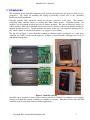
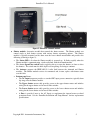
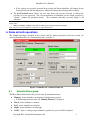
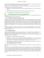
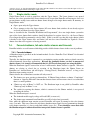
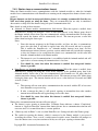
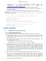
DomePro
User’s Manual
Copyright 2011 Astrometric Instruments, Inc.
Last revision date: 20-Nov-2011
For firmware and software version 1.10.000
This document can be ordered as Astrometric Instruments’ part number DOC-18
DomePro User’s Manual
Table of Contents
1.
2.
3.
Introduction ................................................................................................................................................ 3
System components .................................................................................................................................... 4
Software installation ................................................................................................................................... 6
3.1. DomePro.exe software installation ...................................................................................................... 6
3.2. Setting up the USB connection ............................................................................................................ 7
4. First power-up ............................................................................................................................................ 7
5. DomePro settings........................................................................................................................................ 8
5.1. The Settings tab ................................................................................................................................... 8
5.2. Protected settings in DomePro.exe ...................................................................................................... 8
6. Dome azimuth operations ........................................................................................................................... 9
6.1. Azimuth Status group .......................................................................................................................... 9
6.2. Homing the dome............................................................................................................................... 10
6.3. Left/Right motion .............................................................................................................................. 10
6.4. GoTo azimuth position ...................................................................................................................... 10
6.5. Parking the dome ............................................................................................................................... 10
6.6. Slaving dome azimuth to telescope position...................................................................................... 11
6.7. Azimuth timeout ................................................................................................................................ 13
7. Dome shutter operations ........................................................................................................................... 14
7.1. Shutter status ...................................................................................................................................... 14
7.2. Opening and closing the shutters ....................................................................................................... 14
7.3. Single shutter mode ........................................................................................................................... 15
7.4. Forced shutdown, fail-safe shutter closure and timeouts ................................................................... 15
8. Functional upgrades.................................................................................................................................. 17
8.1. DomePro.exe upgrades ...................................................................................................................... 17
8.2. DomePro firmware upgrades ............................................................................................................. 17
9. Further information .................................................................................................................................. 18
9.1. Diagnostics and trouble shooting ....................................................................................................... 18
9.2. Other documentation.......................................................................................................................... 19
10.
Appendix A: setting up DomePro for Software Bisque’s TheSky software ......................................... 20
Copyright 2011 Astrometric Instruments, Inc.
2
DomePro User’s Manual
1. Introduction
This document details DomePro components and describes their functions and operation from a user’s
perspective. For details on installing and setting up DomePro systems refer to the “DomePro
Installation and Setup Manual”.
DomePro provides fully automated control of telescope enclosures of all types. This includes
controlling dome azimuth motors for rotation and dome shutter motors. DomePro includes two
modules: one for azimuth operation and one for shutter operation. The two are linked by wireless or
cabled interface. Roll-off or clamshell observatories can be controlled with just one shutter module (no
azimuth module necessary). Various azimuth and shutter motor types are supported including DC or
AC “on/off” motors or step/direction motors (e.g. stepper or servo motors).
The left side of Figure 1 shows DomePro azimuth and shutter modules configured as a stand-alone
controller for 12VDC motors and the right side of Figure 1 shows DomePro configured for use in an
Ash Manufacturing dome.
Figure 1: DomePro variants
DomePro can be operated via user interface software provide for Windows™ computers or via external
switches or handpaddle control (requiring no computer to operate). DomePro provides full ASCOM
compliancy for use with many other astronomy applications.
Copyright 2011 Astrometric Instruments, Inc.
3
DomePro User’s Manual
2. System components
All DomePro variants have similar components. Using Astrometric’s DomePro system for Ash domes
as an example the following items comprise the typical DomePro system:
♦ Azimuth module: electronics module that controls the azimuth motor and thus the rotation of the
telescope dome. The Azimuth module is typically mounted on the wall near the azimuth rotation
motor and provides the following (referring to figure 2):
The Keylock power switch is used to turn the DomePro’s power on or off. When off the key
can be removed. When on the key cannot be removed.
The Stop switch is an emergency-stop switch and when pressed-in the switch will latch in the
off position and dome azimuth and shutter power is off. Rotate the switch clockwise to
unlatch it and reapply power.
The Status LED is lit when the Azimuth module is powered up. It flashes slowly when the
Azimuth module is communicating with DomePro software on the computer.
The Left/Right dome rotation switch can be toggled to the left or right causing dome rotation
in the corresponding direction.
Power control for Shutter module: In typical dome installations the Azimuth module
provides power to the Shutter module through electrical slip rings. These allow the dome to
rotate while conducting power to the Shutter module installed on the rotating dome. The power
for the Shutter module is provided from the Azimuth module thus when the Azimuth module
is powered off so is the Shutter module.
The Antenna supports the IEEE 802.15.4 radio link between the Azimuth and Shutter
modules.
Side-panel items:
• The AC Input connector provides a standard IEC input power connection for the
DomePro system.
• The AC to Shutter connector provides a standard IEC output power connection, typically
through electrical slip rings, to the Shutter module.
• The Azimuth Motor cable provides power to the azimuth rotation motor. For systems
using servo motors for azimuth rotation a second feedback cable connects the motor’s
rotation sensor back to the Azimuth enclosure.
• The Com connector provides connection (via cable supplied by Astrometric’s) to a USB or
RS232 communications port on the computer running DomePro software.
• The ShDn connector allows for other electronics devices, such as a weather station, to
shutdown the dome (close the dome shutters).
• The Enc connector accepts the cable to the azimuth rotation sensor or encoder. Note:
DomePro systems using servo or stepper motors for azimuth rotation do not use a rotation
sensor.
• The Home connector provides connection to the azimuth rotation home position switch.
• The HP connector provides connection to an optional handpaddle that provides left and
right dome rotation.
• Fuses (labeled L1 and L2) are provided, for both sides of the AC line, to supplement the
internal motor overload protection circuit and protect the shutter output power connection,
which typically provides power to the Shutter module through slip rings, from electrical
overload. See the “DomePro Installation and Setup Manual” for fuse replacement
specifications.
Copyright 2011 Astrometric Instruments, Inc.
4
DomePro User’s Manual
Figure 2: DomePro Azimuth module
♦ Shutter module: electronics module that controls the shutter motors. The Shutter module can
control single or dual shutter systems with various shutter sequencing options. The Shutter
module is typically mounted on the dome near the lower shutter motor/winch and provides the
following (referring to figure 3):
The Status LED is lit when the Shutter module is powered up. It flashes rapidly when the
Shutter module is communicating, via the radio link, with the Azimuth module.
The shutter Open/Close switch can be toggled to the up to open the shutters or down to close
the shutters. The switch must be held depressed for opening or closing to continue.
The Antenna supports the IEEE 802.15.4 radio link between the Azimuth and Shutter
modules. The Shutter module receives its commands and, in turn, replies with shutter status
over this link.
Bottom-panel items:
• The AC Input connector provides a standard IEC input power connection, typically from
slip rings, into the Shutter module.
• The Upper shutter motor cable provides power to the upper shutter motor and includes
wiring for the upper shutter end-of-travel limit switches.
• The Lower shutter motor cable provides power to the lower shutter motor and includes
wiring for the lower shutter end-of-travel limit switches.
• A Fuse is provided (next to the AC Input) to supplement the internal motor overload
protection circuit. See the “DomePro Installation and Setup Manual” for fuse replacement
specifications.
Copyright 2011 Astrometric Instruments, Inc.
5
DomePro User’s Manual
Figure 3: DomePro Shutter module
♦ DomePro software: DomePro can be operated via user interface software provide for Windows™
computers. This software, referred to in this document as DomePro.exe, provides access to all the
features of the DomePro controller electronics residing in the Azimuth and Shutter modules.
DomePro.exe connects to the Azimuth module via USB or RS232 and then from there to the
Shutter module via radio link. DomePro.exe provides a 100% compliant ASCOM Dome interface
allowing the dome to be controlled from a wide selection of other Windows™-based software.
3. Software installation
This document does not provide instructions for installing DomePro. For installing and setting up a
DomePro system refer to the “DomePro Installation and Setup Manual”.
The remainder of this user’s manual assumes that the DomePro system has been properly installed by
qualified personal and electrical functionality has been verified. It is also assumed that the DomePro
system has been properly configured for the installed application with all settings (assessable from
DomePro.exe’s Settings tab) pre-established.
3.1.
DomePro.exe software installation
To install DomePro.exe on a Windows™-based computer follow these steps:
1. Download and install the latest ASCOM Platform from ascom-standards.org. The ASCOM
Platform is necessary to run DomePro.exe.
2. Download and run the DomeM_NN_RRR.exe installation program, where “M_NN_RRR” is the
latest software version (e.g. “1.10.000”) from www.astrometric.com/support/PeriphSupport.htm.
3. Follow the steps in the installation program to complete the DomePro.exe installation.
Note: some DomePro.exe software upgrades require a mating upgrade of the firmware residing inside
the Azimuth and Shutter control modules. Refer to the “Functional Upgrades” section for firmware
upgrade instructions.
Copyright 2011 Astrometric Instruments, Inc.
6
DomePro User’s Manual
3.2.
Setting up the USB connection
DomePro.exe connects to the Azimuth module via an extended length USB connection that can be up to
50 feet (15 meters) long. Connection lengths up to 1600 feet (500 meters) are optionally available.
Contact Astrometrics for more information.
Note: the communications cable shipped with DomePro includes a standard DB9-based RS232
connecting into a USB-to-RS232 converter. If there is a spare RS232 port already available on the
computer then this cable can be directly used without the converter.
If a USB connection is to be used follow test steps to install the converter’s driver software:
1. Connect the USB cable into a spare USB port on the computer running DomePro.exe.
2. Status indicating that a new USB device has been found will appear on the Windows task bar.
3. If a query window appears asking to search the Internet or to search a location on the computer
for the drivers choose to search on the computer. Then:
a. Switch to Windows Explorer or My Computer and un-zip the USB-Drivers.zip file from the
USB_Drivers folder under the DomePro installation folder (e.g. c:\Program
Files(x86)\Astrometric\DomePro\USB_Drivers\USB-Drivers.zip) into a temporary folder…
note the name of the temporary folder.
b. Switch back to the query window and specify the temporary folder location, and sub-folder
for your operating system version, as the search location. Windows should then find and
install the necessary USB driver.
4. Right-click on My Computer (Windows XP) or Computer (Windows 7) and select Properties and
then Device Manager.
5. In the Device Manager, expand the list of devices under “Ports (COM & LPT)” and note the
COM port that is assigned to “USB Serial Port”. This will be the COM port that DomePro.exe
will use.
4. First power-up
Power-on the DomePro hardware and start the DomePro.exe software. From the DomePro.exe Settings
tab select the Com Port that was found above. DomePro.exe should now connect to the hardware as
indicated by valid status being displayed on the Actions/Status tab. If DomePro.exe is not connected to
the hardware then the Azimuth Status and Shutter Status on the Status/Actions tab will display <NOT
CONNECTED> with a gray background.
When DomePro hardware is powered-up the Status LEDs will light indicating that the modules are
receiving power. When a given module receives a valid communications command then the Status LED
flickers off. The azimuth module Status LED will flicker when it is communicating with the computer.
The shutter module Status LED will continuously flicker if it is properly communicating with the
azimuth module via its radio connection.
Copyright 2011 Astrometric Instruments, Inc.
7
DomePro User’s Manual
5. DomePro settings
5.1.
The Settings tab
DomePro system settings are accessed from DomePro.exe’s Settings tab (figure 4).
Figure 4: DomePro.exe’s Settings tab
The settings accessible from the Settings tab are “instrumental” settings. Instrumental settings are
settings which describe the details of the system hardware and are infrequently accessed or changed.
Instructions for DomePro’s settings are described, as needed, in the Azimuth and Shutter operations
sections below but the primary source of detail on settings can be found in the “DomePro Installation
and Setup Manual”.
5.2.
Protected settings in DomePro.exe
Since proper operation of DomePro requires that proper instrumental settings are maintained in the
Settings tab in DomePro.exe, and since these settings are infrequently changed, the Settings tab has a
password protection feature to prevent inadvertent changes.
The following describes the Settings tab password protection feature so that the observatory
administrator can configure and use DomePro as necessary.
The Settings Protection group on the Settings tab has two buttons with the following function:
♦ The Protect checkbox toggles between the settings being protected or unprotected:
If the settings are presently unprotected then pressing the Protect checkbox will prompt for the
Settings Password and then protect or lock all settings from being changed. When the settings
are locked then the frames surrounding the settings on the Settings tab are grayed out and the
settings cannot be edited.
Copyright 2011 Astrometric Instruments, Inc.
8
DomePro User’s Manual
If the settings are presently protected then pressing the Protect checkbox will prompt for the
Settings Password and then unprotect or unlock all settings thus allowing them to change.
♦ The Set Password button allows any user who knows the present password to change the
password to a new password. For a fresh installation of DomePro.exe the default password is
“default” (without the quotation marks). The maximum allowable password length is 20
characters.
Note: if the password is forgotten it can be viewed by using the Windows™ Registry Editor and inspecting the following
Registry Key
HKEY_CURRENT_USER/Software/VB and VB Program Settings/DomePro/SettingsPW
Note: the password can be different for each user account in Windows™.
6. Dome azimuth operations
The azimuth operations described in this section, and the shutter operations in the next section, are
accessed from DomePro.exe’s Status/Actions tab (see figure 5).
Figure 5: DomePro.exe’s Status/Actions tab
6.1.
Azimuth Status group
The Move Mode field indicates the present status of azimuth movement:
♦ “Homing”: dome azimuth is moving left to find the home position
If the homing operation times-out “Homing Timeout” is displayed
♦ “Fixed”: dome azimuth is stationary
♦ “Left”: dome azimuth is moving left
♦ “Right”: dome azimuth is moving right
♦ “GoTo”: dome is seeking a target azimuth as specified as part of a GoTo command
Copyright 2011 Astrometric Instruments, Inc.
9
DomePro User’s Manual
If the dome is going to the park position then “GoTo: Park Position” is displayed
♦ “Slaved: Fixed”: dome azimuth is slaved to telescope azimuth and is stationary
♦ “Slaved: GoTo”: dome azimuth is slaved to telescope azimuth and seeking a new target azimuth
to position the dome shutters such that the telescope can clearly view the sky.
If the dome is stationary, the Move Mode field background color is green. When moving, the
background color is yellow. If there is a timeout the background color is red.
6.2.
Homing the dome
The first step to operating DomePro is to home the dome. This provides the basis for azimuth position.
Homing motion moves from left to right until the home switch is found. To home the dome press the
Home button under the Azimuth Actions group.
To save time homing, the dome can be powered-off (or parked) somewhat to the left of the home
position so that at next power-up the homing operation (which moves to the right) is shortened. Without
this step the homing operation could involve up to a full revolution of the dome. Note: be sure to set a
park position that is far enough to the left of the home position to allow the azimuth motor to fully
accelerate prior to hitting the home switch.
After the dome has been homed, the At Home status next to the Home button will display “Yes”.
Additional home Switch status is provided which indicates when the home switch is engaged (i.e. when
it is closed-circuit). DomePro detects the home position when the home switch transitions from opencircuit to closed-circuit.
Note: At Home is not the same as the home switch being engaged. The distinction is:
♦
At Home indicates the state following a homing operation where DomePro has found the first instant of the home
switch being engaged when moving in azimuth from left to right. At Home is an accurate reference-point in azimuth.
If the dome is commanded to move at all in azimuth when “At Home” then At Home is cleared.
♦
The home switch indicator simply means that the home switch is engaged (i.e. closed-circuit). The home switch
might be engaged over a broad range of azimuth and is not necessarily an accurate azimuth reference point but simply
an indication that the home switch is active. It is the transition of the home switch from open-circuit (disengaged) to
closed-circuit (engaged) that accurately determines home position.
6.3.
Left/Right motion
The Left and Right buttons under the Azimuth Actions group start dome rotation in their respective
directions. To stop the dome rotation press the Halt button.
Note: when using On/Off motors DomePro prevents instant motor direction reversal by inserting a 3
second delay between energization in one direction and energization in the opposite direction. This is to
prevent motor overload and prevent a problem with some AC motors where the motor continues in the
same direction when the power is instantly reversed.
6.4.
GoTo azimuth position
To move the dome azimuth to an arbitrary position enter the desired position in the box to the left of the
GoTo button (in the Azimuth Actions group) and press the button to start movement. The dome will
rotate to the selected azimuth and stop.
6.5.
Parking the dome
If a park position is defined (i.e. “marked”) then the Park button will start a GoTo with the park position
as destination. To define the park position, move the dome to the desired park position and press the
Mark Park button on the Settings tab Azimuth group. Before marking the Park position, assure that the
dome azimuth is properly preset from home position (i.e. that the dome has been homed). Alternatively,
Copyright 2011 Astrometric Instruments, Inc.
10
DomePro User’s Manual
the azimuth of the Park position can be entered into the Park Azimuth box. So long as the number is
valid (i.e. >= 0.0, <= 360.0) then this will become the park position.
Defining and using the Park position can have several useful purposes including providing a powerdown (and hence power-up/starting) position that is:
♦ Somewhat to the left of the home position such that homing (which moves from left to right) is
shorter.
♦ At an azimuth that is best positioned for the dome to provide weather protection.
♦ At an azimuth that is best positioned to open or close the shutters.
6.6.
Slaving dome azimuth to telescope position
DomePro provides a feature where dome azimuth position can be “slaved” to the azimuth position of an
ASCOM-compliant telescope control system.
6.6.1. Selecting the telescope control system
DomePro.exe will slave the dome azimuth position to the telescope such that the telescope is nominally
viewing through the center of the dome shutter aperture at all times. DomePro.exe will slave dome
azimuth with any ASCOM complaint telescope control system which supplies Right Ascension,
Declination and Sidereal time. To select the telescope control system to use click the Choose Scope
button in the Telescope group on the Settings tab. This will open the standard “ASCOM Chooser”
dialog box from which there is a drop-down menu of available telescope control systems to choose
from.
Note: Software Bisque’s TheSky software does not directly support ASCOM however instructions are
provided in Appendix A for setting up DomePro to work with TheSky through a 3rd-party “TheSkycontrolled Telescope driver”.
6.6.2. Enabling slaving
To slave the dome azimuth to telescope position click the Slave Az checkbox in the Azimuth Group on
the Status/Actions tab. This feature is un-checked at startup (i.e. it is not saved between sessions).
When Slave Az is selected then DomePro.exe will attempt to connect to the selected telescope through
ASCOM. Slaving is not allowed if:
♦ DomePro.exe is not connected to DomePro hardware.
♦ DomePro.exe cannot connect to the selected telescope's ASCOM driver. Note: in addition to
DomePro.exe connecting to the ASCOM driver the ASCOM driver needs to be connected to the
telescope hardware. The method to accomplish this depends on the telescope system.
♦ If the telescope is controlled by Astrometric’s Maestro/SkyWalker then slaving is not allowed if
celestial alignment has not been completed.
♦ If the Azimuth Move Mode is not “Fixed”.
If any of the above requirements are not maintained while the azimuth is slaved then slaving will be
canceled.
When Slave Az is selected DomePro will poll the telescope position once per second and calculate the
necessary dome azimuth via a detailed geometry model described in the next section. If the difference
between present dome azimuth and present telescope position exceeds the cosecant of telescope altitude
(i.e. 1/cos(altitude)) multiplied by the value in the Telescope-Dome Delta setting (Azimuth group on
Settings tab) then DomePro will issue a GoTo to synchronize the dome position with the telescope
position.
Copyright 2011 Astrometric Instruments, Inc.
11
DomePro User’s Manual
The status of azimuth slaving is provided on the Actions/Status tab below the Choose Scope button and
includes:
♦ “Slaved”: dome azimuth position is slaved to telescope azimuth position
♦ “No Dome Connect”: DomePro.exe is not connected to DomePro hardware
♦ “No Scope Connect”: DomePro.exe is not connected to the telescope ASCOM driver and/or the
telescope ASCOM driver is not connected to the telescope hardware.
♦ “No Scope Align”: the telescope controlled by Maestro/SkyWalker is not celestial aligned.
♦ “Not Slaved”: dome azimuth position is not slaved to telescope azimuth position but could be
slaved if the above criteria have been met.
When dome azimuth slaving is operating and stationary the Move Mode is “Slaved: Fixed”. If the dome
is moving to match dome position to telescope position the Move Mode is “Slaved: GoTo”. Pressing
any azimuth action button on DomePro.exe (i.e. Left, Right, Home) will clear the Slave Az checkbox
and raise the message “Slave to Telescope Azimuth canceled”. Pressing the Left or Right buttons on the
DomePro azimuth hardware module will also cancel slaving (with no message).
6.6.3. Setting up telescope/dome geometry
DomePro.exe incorporates a geometric model of dome rotation where, when slaving is enabled, the
shutter's center line is aligned with the point where the telescope line of sight crosses the dome surface.
Fork-type equatorial mounts and German equatorial mounts (GEM) are supported. Fork mounts
represent the general case and include split-ring mounts.
DomePro.exe includes a Telescope settings area on the Settings tab where geometry settings are entered.
For these geometry settings, the Pivot point (see 'P' in figure 6) is defined as:
♦ For a fork mount: the intersection of the RA axis with a plane which contains the Dec axis and is
perpendicular to the RA axis.
♦ For a GEM: the intersection of the RA and Dec axes.
All geometry settings values are in units of dome diameter unless otherwise noted. For example, a value
of 0.5 meter in a 5 meter diameter dome is entered as 0.1. The accuracy of these parameters is not
critical and simple measurements with a tape measure should suffice.
The position of the pivot point within the dome is defined by two parameters:
♦ Pivot offset north: the offset of the pivot point northward from dome center (negative for
Southward offset). Values between -0.2 and 0.2 are allowed.
♦ Pivot offset vertical: the offset of the pivot point vertically from dome center (negative value for
downward offset). Values between -0.2 and 0.2 are allowed.
Once the location of the pivot point is established, the following settings are used to further define
telescope geometry:
♦ Latitude: enter the site latitude (negative for southern hemisphere). See 'L' in figure 6.
♦ Mount type: choose a Fork mount or GEM. For each mount type the following geometry values
are available:
Fork mount: Dec offset from RA: the offset of the Dec axis from the RA axis in a direction
perpendicular to the RA axis. See 'A' in figure 6. Values between -0.2 and 0.2 are allowed. A
positive value is upwards as shown in figure 6.
For GEM: Optical offset from RA: the offset of the optical axis from the RA axis along the
Dec axis. See 'B' in figure 6. Values between 0.0 and 0.2 are allowed. Note: for a GEM
telescope, DomePro needs to know the “side of pier” that the telescope sits to properly set the
Copyright 2011 Astrometric Instruments, Inc.
12
DomePro User’s Manual
Optical offset from RA either East or West. To specify this, the “GEM Side” drop-down
menu allows for selection of:
• “Looking East”: the GEM telescope is setup to view the Eastern sky (i.e. the telescope tube
is offset along the Dec axis Westward).
• “Looking West”: the GEM telescope is setup to view the Western sky (i.e. the telescope
tube is offset along the Dec axis Eastward).
• “From ASCOM”: the ASCOM telescope interface is queried for the “side of pier” that the
telescope is presently on so that the Optical offset from RA can be properly applied East or
West. Note: if the ASCOM telescope interface does not implement the SideOfPier
property then an error message is raised and azimuth slaving is prohibited.
Figure 6: DomePro.exe’s telescope geometry parameters
Note: the dome azimuth computations in DomePro utilize algorithms provided by Paulo Holvorcem as
implemented in his Tools for Automated Observing (TAO) and are used with his permission. More
information on TAO is available at http://sites.mpc.com.br/holvorcem/tao/readme.html.
6.7.
Azimuth timeout
The Azimuth timeout (Settings tab, Azimuth group) specifies the maximum amount of time that an
azimuth homing, GoTo or park operation is allowed to complete and can range from 10 to 1000 seconds.
The purpose of this timeout is to prevent non-stop dome rotation if the azimuth rotation sensor is nonfunctional (for On/Off motors) or the home switch is not found in a homing operation.
If this timeout occurs then motion is terminated and the Move Mode field (Actions/Status tab, Azimuth
Status group) displays “Azimuth Timeout” and is highlighted in red. To clear the timeout condition a
new dome azimuth movement operation must be initiated.
To set the Azimuth timeout the amount of time it takes the dome to make a full rotation should be
measured and then inflated by 10%-20% to allow for variance in motor speed.
Note: timeouts will not occur for GoTo or park operations for Step/Dir motors since for these types of
motors DomePro does not use an azimuth rotation sensor to measure position but rather moves the
motors to the necessary destination in an open-looped manor which runs no risk of continuous/non-stop
rotation.
Copyright 2011 Astrometric Instruments, Inc.
13
DomePro User’s Manual
7. Dome shutter operations
7.1.
Shutter status
The field at the top of the Shutter Status group on the Status/Actions tab (figure 5) indicates the present
status of the shutters:
♦ "Opened": the shutters are opened and are up against the opened limit switches
♦ "Opening": the shutters are opening and have not yet completed movement to the opened limit
switches.
♦ "Closed": the shutters are closed and are up against the closed limit switches
♦ "Closing": the shutters are closing and have not yet completed movement to the closed limit
switches.
♦ "Intermediate": the shutters are stationary and neither opened nor closed. This state can result if
an open or close operation is terminated/halted prior to completing.
♦ "Closed: Shutdown asserted": shutters are closed and the Azimuth Module’s shutdown input is
asserted.
♦ "Closing: Shutdown asserted": shutters are closing and the Azimuth Module’s shutdown input
is asserted. In this state it is likely that the shutdown assertion was the cause of the closure.
♦ "No Shutter Control": the Azimuth Module cannot find and is not communicating with the
Shutter Module.
♦ "<various> Timeout": a shutter timeout has occurred. The status indicates which timeout
(described below) is the cause.
If the shutters are opened or closed the status field background color is green. When moving, or in the
intermediate state, the background color is yellow. If there is a timeout the background color is red. If
there is no shutter control the background color is gray.
7.2.
Opening and closing the shutters
There are two means to open and close the shutters:
1. Using the Shutter Module’s Open/Close switch: toggle this switch up to open the shutters or
down to close the shutters. The switch must be held depressed for opening or closing to continue.
To halt shutter opening/closing simply release the toggle switch.
2. Click the Open or Close buttons in the Shutter Actions area on the Status/Actions tab. When
either of these buttons is clicked the open or close operation will start and continue until it is
completed or a timeout (described below) occurs. To halt shutter opening/closing press the Halt
button.
Note: Some AC motors (notably: 120VAC shutter motors used on Ash Manufacturing domes) will not physically reverse if
they are electrically reversed too quickly. Additionally, some motors will overload if reversed too quickly. To prevent
instant motor reversal, DomePro will block shutter direction reversal for 3 seconds after motor energization terminates in the
former direction. When direction is reversed the motors will be de-energized instantly however DomePro will continue to
report Shutter Status for the previous direction until the 3 seconds has elapsed and the motors are energized in the reverse
direction. One side effect of this feature is that if a new open or close is requested while it is in the process of opening or
closing (i.e. a same direction request) then DomePro will halt motion for 3 seconds just as if it were going to reverse the
motor direction.
Note: DomePro firmware implements a 1 second glitch rejection on reading shutter limit switches. This 1 second interval
was found to be necessary on some Ash installations where the limit switch would spring back for a large fraction of a second
causing a false reading. Due to this feature a shutter Intermediate status will result when letting go of the open or close
switch right after the motor has stopped but before the Opened or Closed shutter status is indicated on DomePro. This is
because it takes approximately 1 second for DomePro to register that the limit switch is engaged and the shutter is fully
Copyright 2011 Astrometric Instruments, Inc.
14
DomePro User’s Manual
opened or closed. To clear the Intermediate status either hold the switch for more than 1 second after the Open or Close or
press the switch again until the status flips to Open or Close.
7.3.
Single shutter mode
Single Shutter mode is used to open/close only the Upper shutter. The Lower shutter is not opened
however for a close operation if the Lower shutter reads as open then DomePro will attempt to close it to
prevent shutter overlap issues with two-shutter domes being used in single-shutter mode. In summary, in
Single Shutter mode:
♦ Open: opens only the Upper shutter.
♦ Close: attempts to close the Lower shutter (if Lower shutter limit switches do not already register
as closed) and then closes the Upper shutter.
Note: as described in the “DomePro Installation and Setup manual”, for a true single shutter system the
state of the lower shutter limit switches should be hardwired to register closed (i.e. the Lower Shutter
Closed input should be permanently wired to Gnd). If this is not the case then the single shutter (which
is hooked to the Upper shutter drive and limits) will not close since DomePro has signaled a Lower
shutter close that never registers as having occurred.
7.4.
Forced shutdown, fail-safe shutter closure and timeouts
DomePro includes several features which help provide reliable shutter closure in the event of problems.
7.4.1. Forced shutdown
A Shutdown input is provided on the Azimuth module. See the “DomePro User's Manual” for electrical
interfacing details.
Typically, the shutdown input is connected to a precipitation sensing weather station or cloud sensor for
remote/automated observatory applications. Because the shutdown feature can lead to unexpected
shutter closure, it is strongly recommended that it is NOT used when people are using the dome.
When the Shutdown signal is asserted for at least 1 millisecond a shutter closure is signaled. When the
shutters are closing or closed due to assertion of the Shutdown input, the Shutter Status on
DomePro.exe's Actions/Status tab will display “Closing(Closed): Shutdown asserted” so long as the
Shutdown input remains asserted.
Shutter closure due to Shutdown assertion will only occur if:
♦ The shutters are open, opening or intermediate. If Shutter Status indicates a shutter “Completion”
timeout or “Opposite Direction” timeout then shutter closure will not occur since it is assumed that
there is a motor problem.
♦ “Shutter op only At Home” is NOT set. The Shutdown input is not polled by DomePro when
“Shutter op only At Home” is set.
♦ The switch for opening the shutters, which is connected to the Shutter module, is not pressed
overriding the closure.
When the Shutdown input is asserted:
♦ The Azimuth module supply voltage will read 0.0V (or near to it).
♦ The shutter open command from DomePro.exe will be locked-out (prevented).
Note: while the shutdown input remains asserted DomePro will repeat its attempt to close the shutters
every 5 seconds. This retry reduces the risk that a shutdown input signal does not communicate through
to the shutter controller (e.g. due to radio link stability issues, etc.). Users should be aware that when
the Shutdown input is connected/used that unexpected shutter closure is possible.
Copyright 2011 Astrometric Instruments, Inc.
15
DomePro User’s Manual
7.4.2. Shutter close on communications timeout
When the Shutter module looses communications with the Azimuth module or when the Azimuth
module looses communications with DomePro.exe running on the computer then shutter closure can be
signaled.
Because timeouts can lead to unexpected shutter closure, it is strongly recommended that they are
NOT used when people are using the dome. They are recommended for use only in automated
observatories to help avoid the shutters being left open if communications fail.
More details on each of these timeouts:
♦ Azimuth -to- Shutter module communications link timeout: When this option is enabled, from
DomePro.exe's Settings tab using the “Close on radio link timeout” in the Shutter group, then if
the Shutter module detects that it has not communicated with the Azimuth module for more than
about 20 seconds the shutters will be automatically closed. This timeout prevents a radio link
failure from leaving the dome open.
Notes:
• Since this timeout originates in the Shutter module, and does not have to communicate
across the radio link, it will only be applied once after 20 seconds and not be repeated.
This is unlike the DomePro.exe –to- Azimuth module timeout (next item) and the
shutdown input initiated closure (previous section) which both will periodically reattempt
to close the shutters to be certain that the closure was communicated via the radio link
from the Azimuth module to the Shutter module.
• The timeout is reset if communications is reestablished with the Azimuth module and will
again lead to a closure attempt if communications is lost later.
• User should be aware that when this timeout is enabled that unexpected shutter
closure is possible.
♦ DomePro.exe -to- Azimuth module communications timeout: When this option is enabled, from
DomePro.exe's Settings tab using the “Close on PC timeout” in the Azimuth group, then if the
Azimuth module detects that it has not communicated with DomePro.exe for more than the
settable timeout the shutters will be automatically closed. This timeout prevents a PC failure from
leaving the dome open. The timeout duration can be set to a value between 10 seconds and 3600
seconds (1 hour).
Notes:
• This timeout will not occur unless communications has occurred with the PC at least once
since DomePro was powered-up.
• If after a timeout the dome is still opened, opening or intermediate then after another
timeout interval DomePro will again attempt to close the dome.
User should be aware that when this timeout is enabled that unexpected shutter
closure is possible.
Shutter close on communications timeout will occur only if:
♦ The shutter is open, opening or intermediate. If Shutter Status indicates a shutter “Completion”
timeout or “Opposite Direction” timeout then shutter closure due to communications timeout will
not occur since it is assumed that there is a motor problem.
♦ “Shutter op only At Home” is not set (from DomePro.exe's Settings tab under the Shutter group).
♦ The switch for opening the shutters, which is connected to the Shutter module, is not pressed
overriding the closure. Note: even if a switch-enacted override occurs, DomePro still attempts to
close the shutters once every timeout interval if they are still open, opening or intermediate.
•
Copyright 2011 Astrometric Instruments, Inc.
16
DomePro User’s Manual
7.4.3. Shutter opening/closing timeouts
Any shutter action that uses a limit switch as indication of completion has a timeout to prevent
potentially unending motor activation in the event of, for example, motor failure, failure of mechanical
couplings or limit switch failure. These timeout protections include:
♦ Shutter “Completion” timeouts. The upper and lower shutters have separate Completion timeouts
that are settable via the following fields on DomePro.exe's Settings tab:
“U Shutter timeout” sets the maximum time that DomePro will wait for the upper shutter to
open or close. If more than this amount of time elapses DomePro will turn off the motors and
report either “U Shutter Opening Timeout” or “U Shutter Closing Timeout”.
“L Shutter timeout” sets the maximum time that DomePro will wait for the lower shutter to
open or close. If more than this amount of time elapses DomePro will turn off the motors and
report either “L Shutter Opening Timeout” or “L Shutter Closing Timeout”.
Completion timeouts are settable between 10 and 500 seconds.
♦ The shutter “Opposite direction” timeout specifies the amount of time that the shutter limit switch
in the direction opposite to the requested shutter motion can be active after the shutter motor is
turned on. This timeout serves two purposes:
1. Assures that the motor actually starts and moves the shutter off the end-stop (and opposite
direction limit switch) within a specified period of time. This prevents potential motor damage
if the shutter is jammed and the motor cannot move it.
2. Assures that once the motor is moving that it is moving in the correct direction. It is possible,
with some AC motors, if the starter windings or starter capacitors go bad that they can start in
the wrong direction. If that happens then after the Opposite direction timeout expires the
shutter hitting the limit switch in the opposite direction of its expected movement would be
detected.
The Opposite direction timeout is specified from the “Opposite dir timeout” field on
DomePro.exe's Settings tab and can range from 4 to 240 seconds. As short a timeout as is possible
is recommended so that if a motor is stalled on start it is least likely to be damaged.
Timeout status is reported in the Shutter Status field on the Actions/Status tab with a red-highlighted
background.
A timeout condition is cleared by initiating any new shutter motion (i.e. Open or Close).
8. Functional upgrades
Astrometric Instruments continually improves its products and provides software and firmware
upgrades.
8.1.
DomePro.exe upgrades
Check Astrometric’s support web page at www.astrometric.com/suport/PeriphSupport.htm for the latest
DomePro.exe upgrade status. To install an upgrade following the instructions in section 3.1.
8.2.
DomePro firmware upgrades
Firmware is the software that runs on the microcontrollers inside the Azimuth and Shutter modules.
DomePro.exe upgrades often require firmware upgrades to operate correctly.
Each DomePro.exe upgrade available from Astrometric’s support web page will specify the firmware
versions it will work with. If an upgrade is necessary follow the instructions below. Note: it is
necessary to upgrade the firmware in both the Azimuth and Shutter modules at the same time otherwise
they will not properly function together.
Copyright 2011 Astrometric Instruments, Inc.
17
DomePro User’s Manual
1. Download and run the DomeProFW_M_NN_RRR.exe installation program, where
“M_NN_RRR”
is
the
necessary
firmware
version
(e.g.
“1.10.000”)
from
www.astrometric.com/suport/PeriphSupport.htm.
2. Follow the instructions... first to un-zip the files and then to run the firmware upgrade.
3. The firmware upgrade program will run and display the progression of the upgrade as a
percentage completion.
4. When the upgrade is complete DomePro must be power-cycled to run the new firmware.
The following is an example of the firmware upgrade dialog where the red “com10” is the only
information entered by the user…
C:\Program Files\Astrometric\DomePro\Firmware>PeriphFirmup.exe DomePro1_10_000.hex
=================== Peripheral Firmware Upgrade Program ====================
Hardware model to upgrade: DomePro
Firmware version to upgrade to: 1.10.000
...Press any key to continue...
...Enter COM port to connect to hardware (e.g. "COM1")> com10
0% 5% 10% 15% 20% 25% 30% 35% 40% 45% 50% 55% 60% 65% 70% 75% 80% 85% 90% 95% 100%
Programming is complete. DomePro must be power-cycled prior to use.
...Hit any key to exit...
C:\Program Files\Astrometric\DomePro\Firmware>
9. Further information
9.1.
Diagnostics and trouble shooting
9.1.1. Azimuth module diagnostics
The following Azimuth diagnostics are provided from DomePro.exe's Diagnostics tab (figure 6):
♦ Azimuth module's supply voltage. This is the supply voltage at the input to the Dome Control
Module (DCM). For Ash dome installations this is voltage internal to the Azimuth module and is
of no practical meaning.
♦ The Azimuth Rotation Count field reports DomePro's internal azimuth count/position. This
increments/decrements as follows:
For On/Off motors: once per detection of rotation sensor transition.
For Step/Dir motors: once per step issued to the external motor controller.
♦ Azimuth Rotation Sensor voltage. DomePro’s has the ability to use either a single-channel sensor
that detects light and dark transition or a dual-channel quadrature encoder. When using a single
channel detector it is useful to know the signal level coming from the light/dark transitions to
assure that they form a signal with definitive on and off states. A sufficient signal level is present
if the Azimuth Rotation Sensor voltage transitions from below 2.00 volts to above 4.00 volts.
Note: this field is “N/A” and grayed-out for systems that use step/direction motors on azimuth and
hence do not need a rotation sensor.
♦ The number of errors on the radio link with the Shutter module can be viewed and cleared.
♦ There are various error checks that occur inside the azimuth controller. These are reported as an
error code in the "Azimuth controller error" field. If this field is yellow then a non-critical
communications error has occurred that could indicate problems with the USB/RS-232
communications link between the Azimuth module and the computer running DomePro.exe. If
Copyright 2011 Astrometric Instruments, Inc.
18
DomePro User’s Manual
this field is red then a critical error has occurred and the error code should be reported to
Astrometrics. Any error condition can be cleared with the Clear button.
♦ The status of the Azimuth module's Shutdown input.
9.1.2. Shutter module diagnostics
The following Shutter diagnostics are provided from DomePro.exe's Diagnostics tab (figure 6):
♦ Shutter module's supply voltage. This is the supply voltage at the input to the Dome Control
Module (DCM). For Ash dome installations this is voltage internal to the Shutter module and is of
no practical meaning.
Figure 6: DomePro.exe’s Diagnostics tab
9.1.3. Azimuth and Shutter module radio link error LEDs
The Azimuth and Shutter modules communicate via a 2.4GHz RF or hard-wired link. If this
communications link fails then both modules will retry in an attempt to reestablish communications.
The Shutter module will retry every 150 milliseconds and the Azimuth module every 750 milliseconds.
When communications fails the yellow Link Err LEDs on the DCM circuit boards (internal to the gray
enclosures for Ash Dome systems) will flash. These Link Err LEDs will continue to flash rapidly for
the Shutter DCM and slower for the Azimuth DCM if communications is not re-established.
9.2.
Other documentation
Refer to the following for further information on the DomePro system:
♦ For installation, setup instructions, trouble shooting and maintenance refer to the “DomePro
Installation and Setup Manual” (Astrometric part number DOC-26).
♦ For details on DomePro.exe’s support for the ASCOM Dome interface standard refer to
“DomePro support for ASCOM” (Astrometric part number DOC-19).
Copyright 2011 Astrometric Instruments, Inc.
19
DomePro User’s Manual
♦ For details on DomePro’s hardware subset support for the Astrometric Telescope Control
Language (ATCL) serial interface protocol refer to “SkyWalker Client Interface Specification and
Programming Guide” (Astrometric part number DOC-11) and “Astrometric's Peripheral Device
Client Interface Specification and Programming Guide” (Astrometric part number DOC-22).
10. Appendix A: setting up DomePro for Software Bisque’s TheSky
software
These instructions are for setting up DomePro to slave azimuth position to “TheSky-controlled
Telescope”. This includes Software Bisque's Paramount and any telescope controlled by TheSky.
It is assumed that you have TheSky6 or TheSkyX already installed.
Follow these steps:
1. Install the latest version of the ASCOM Platform (6.0 as of this writing) from http://ascomstandards.org. Note: this step is likely already completed as part of installing/upgrading
DomePro.
2. Download and install TheSky-controlled Telescope ASCOM driver per instructions at
http://ascom-standards.org/Downloads/ScopeDrivers.htm. Scroll down the page to the section
titled "TheSky Controlled Telescope (Paramount, etc.) for TheSky X and TheSky 5/6".
Additional instructions are included at: http://ascom-standards.org/FAQs/TheSky.htm under the
section titled "TheSky Using its Internal Telescope Logic (e.g. Paramount)"
3. From DomePro's Settings tab click "Choose Scope" in the Telescope group. The ASCOM
Telescope Chooser will pop-up.
Select "TheSky-controlled Telescope".
Click "Properties" and make settings as desired and click OK.
Be sure that TheSky is connected to the telescope and that telescope is pointing as indicated on
TheSky's star map.
4. From DomePro's Status/Actions tab click on "Slave Az" and the dome should rotate to match
where the telescope is pointing on TheSky's star map.
Copyright 2011 Astrometric Instruments, Inc.
20