1
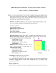
Comparison: The power B is more than power A..
P/ PA =(PB— PA)/ PA=32..3%
As a result of different manufacture of solar panels, different solar illumination intensity, different
temperature, different efficiency of solar charge controller and so on. The effective power
increase rate is 10-30%.
Choose the model:
Solar Panel: 12V solar system should use 40pcs cells laminated solar panel. The maximum
power point voltage is18V above. 24V solar system should use 2pcs above mentioned solar
panels. 48V solar system should use 4pcs above mentioned solar panels.
Conductor: The cable between solar panel with MPPT solar charge controller should be better
calculated by 1Ampere per 1mm².
Solar Charge Controller: JUTA brand MPPT-10 Model solar charge controller Rated input
Ampere is 10A. We have 12V, 24V and 48V three kinds of MPPT solar charge controllers.
Fit for power of solar panels: 20—200Wp(12V), 40—400Wp(24V), 80-800Wp (48V).
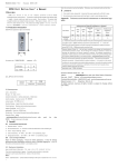
Connection: ( As Picture 3 according to
below process)
1. Connected the “+”, “-” poles of the
battery to the controller ( 3, 4 from left)
firmly and correctly. At this time the
LOAD green LED is bright. If the LOAD
green LED is not bright, it is indicate
there is battery reverse polarity
connection. Only LOAD green LED is
bright, we could continue next step
operation.
2. Connected the “+”, “-” poles of the solar
panel to the controller (1,2 from the left)
firmly and correctly.
3. Connected the “+”, “-” poles of the LOAD to the controller (5,6 from the left) firmly and
correctly.
Simply Measure Methord: For 12V system, measure the input voltage from solar panel
with multimeter (terminal 1, 2 of controller), it is normal if the voltage of solar panel more
than battery voltage 0.5-6V. Generally, the higher input voltage, the better charge
efficiency. For 24v and 48V system, the input voltage will be much more higher than
battery voltage
(Note: It is normal phenomenon the controller can not find Maximum Power Point within
10 minutes from system start.)
Indicator: (Picture 1)
1. Load indicator, green, bright indicate there is output, Load could work, “off” indicate
there is not output, Load can not work.
2. Low Voltage Indicator, red, bright indicate the voltage of the battery is low. Load