1
TIMER B
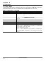
9.2 Block description
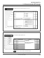
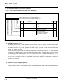
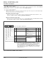
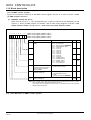
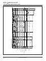
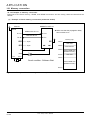
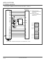
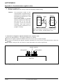
9.2.4 Timer Bi interrupt control register
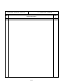
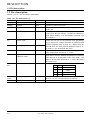
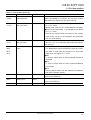
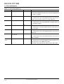
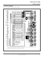
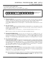
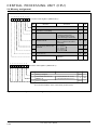
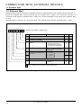
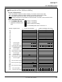
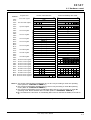
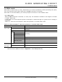
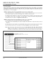
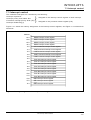
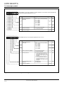
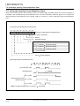
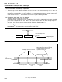
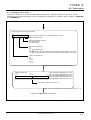
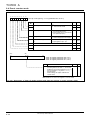
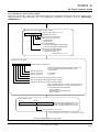
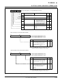
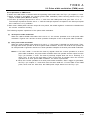
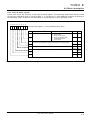
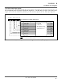
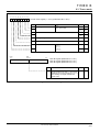
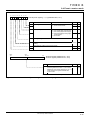
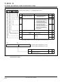
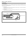
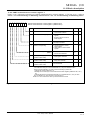
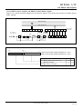
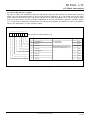
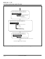
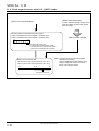
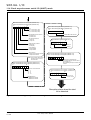
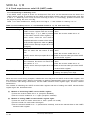
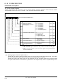
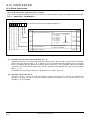
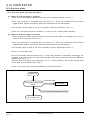
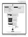
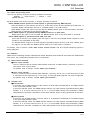
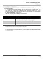
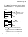
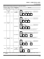
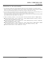
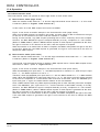
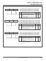
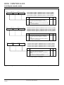
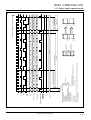
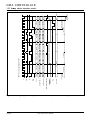
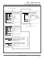
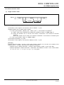
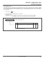
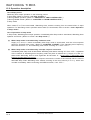
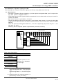
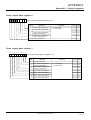
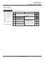
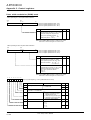
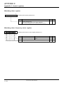
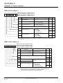
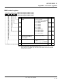
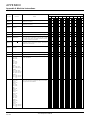
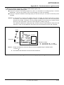
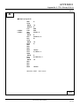
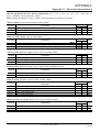
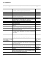
Figure 9.2.4 shows the structure of the timer Bi interrupt control register. For details about interrupts, refer
to “CHAPTER 7. INTERRUPTS.”
b7
b6
b5
b4
b3
b2
b1
b0
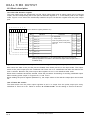
Timer Bi interrupt control register (i = 0 to 2) (Addresses 7A16 to 7C16)
Bit
Bit name
0
Interrupt priority level select bits
1
2
3
Interrupt request bit
7 to 4
Nothing is assigned.
Functions
At reset
RW
0 0 0 : Level 0 (Interrupt disabled)
0 0 1 : Level 1
Low level
0 1 0 : Level 2
0 1 1 : Level 3
1 0 0 : Level 4
1 0 1 : Level 5
1 1 0 : Level 6
1 1 1 : Level 7
High level
0
RW
0
RW
0
RW
0 : No interrupt requested
1 : Interrupt requested
0
RW
Undefined
–
b2 b1 b0
Fig. 9.2.4 Structure of timer Bi interrupt control register
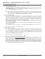
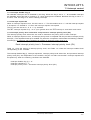
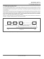
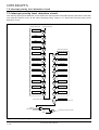
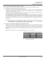
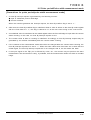
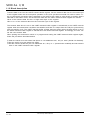
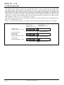
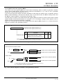
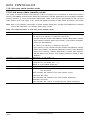
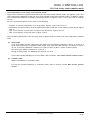
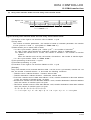
(1) Interrupt priority level select bits (bits 2 to 0)
These bits select a timer Bi interrupt’s priority level. When using timer Bi interrupts, select one of the
priority levels (1 to 7). When a timer Bi interrupt request occurs, its priority level is compared with
the processor interrupt priority level (IPL). The requested interrupt is enabled only when its priority
level is higher than the IPL. (However, this applies when the interrupt disable bit (I) = “0.”) To disable
timer Bi interrupts, set these bits to “000 2” (level 0).
(2) Interrupt request bit (bit 3)
This bit is set to “1” when a timer Bi interrupt request occurs. This bit is automatically cleared to “0”
when the timer Bi interrupt request is accepted. This bit can be set to “1” or cleared to “0” by
software.
9–6
7721 Group User’s Manual