1
CLOCK GENERATING CIRCUIT
5.2 Clocks
5.2 Clocks
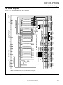
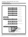
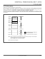
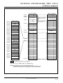
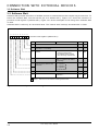
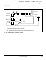
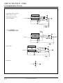
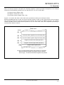
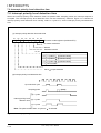
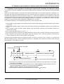
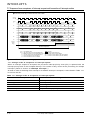
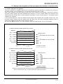
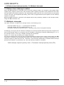
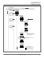
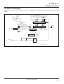
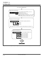
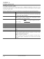
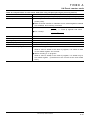
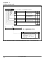
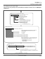
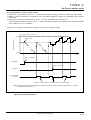
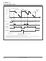
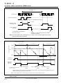
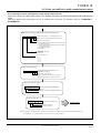
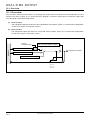
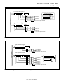
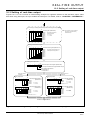
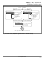
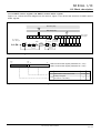
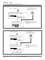
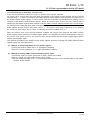
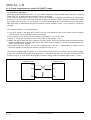
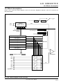
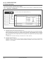
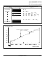
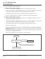
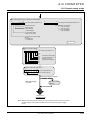
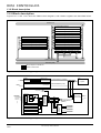
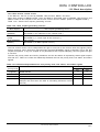
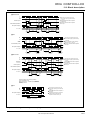
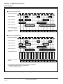
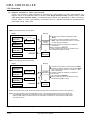
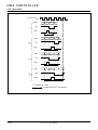
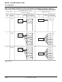
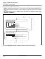
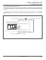
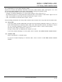
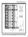
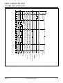
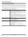
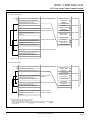
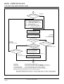
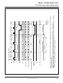
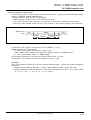
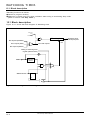
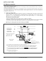
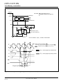
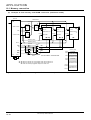
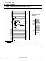
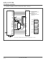
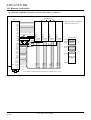
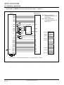
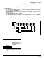
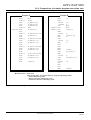
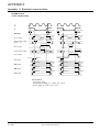
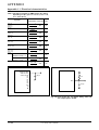
Figure 5.2.1 shows the clock generating circuit block diagram.
f2
XIN
XOUT
f16
1
f64
Interrupt request
S
Q
1/2
1/8
1/2
1/2
1/8
f512
f512 “0”
STP instruction
R
Operation clock for
internal peripheral devices
Watchdog timer
frequency select bit
f32
“1”
S
WIT instruction
Watchdog
timer
Q
R
(Note)
Ready request
Reset
S
R
Q
CPU
CPU wait request
from BIU
Bus request
DRAMC
Hold
DMAC
CPU : Central Processing Unit
BIU : Bus Interface Unit
Watchdog timer frequency select bit : Bit 0 at address 6116
Note: This signal is generated when the watchdog timer’s most significant bit becomes “0.”
Fig. 5.2.1 Clock generating circuit block diagram
7721 Group User’s Manual
5–3