1
GE Fanuc Automation
Programmable Control Products
PANELWARE™
Hardware Installation
User's Manual
GFK - 0848A
June 1995
GFL-002
Warnings, Cautions, and Notes
as Used in this Publication
Warning
Warning notices are used in this publication to emphasize that hazardous voltages, currents,
temperatures, or other conditions that could cause personal injury exist in this equipment or
may be associated with its use.
In situations where inattention could cause either personal injury or damage to equipment, a
Warning notice is used.
Caution
Caution notices are used where equipment might be damaged if care is not taken.
Note
Notes merely call attention to information that is especially significant to understanding and
operating the equipment.
This document is based on information available at the time of its publication. While efforts have been
made to be accurate, the information contained herein does not purport to cover all details or variations in
hardware or software, nor to provide or every possible contingency in connection with installation,
operation, or maintenance. Features may be described herein which are not present in all hardware and
software systems. GE Fanuc Automation assumes no obligation of notice to holders of this document with
respect to changes subsequently made.
GE Fanuc Automation makes no representation or warranty, expressed, implied, or statutory with respect
to, and assumes no responsibility for the accuracy, completeness, sufficiency, or usefulness of the
information contained herein. No warranties of merchantability or fitness for purpose shall apply.
The following are trademarks of GE Fanuc Automation North America, Inc.
Alarm Master
CIMPLICITY
CIMPLICITY
PowerTRAC
CIMPLICITY 90–ADS
CIMSTAR
Field Control
GEnet
Genius
Genius PowerTRAC
Helpmate
Logicmaster
Modelmaster
ProLoop
PROMACRO
Series Five
Series 90
Series One
Series Six
Series Three
VuMaster
Workmaster
©Copyright 1995 GE Fanuc Automation North America, Inc.
All Rights Reserved.
Preface
This manual provides a description of the PANELWARE™ Operator Panels, including Display
modules, Keyblock modules, and Panel Controllers. It contains technical data, installation
instructions and general information on using PANELWARE Operator Panel applications.
Some of the products mentioned or illustrated in this manual may not be released when this
document is published. Please do not rely on any references made to these units. Your local
GE Fanuc distributor will inform you of any new product releases.
Revisions to This Manual
●
●
●
●
Changes made to this manual describe new features of the PANELWARE system hardware.
Additionally, corrections have been made where necessary. The following list describes the
major revisions in this manual, as compared to the previous version (GFK-0848).
Availability of the Genius Panel Controller (C400) — Refer to PANELWARE Application
Manual for Genius Protocol User’s Manual (GFK-1115) for more information.
To aid in sizing the bulk +24 VDC power supply, a consolidated list of power consumption
figures for all PANELWARE components has been added (See appendix C).
Revision B of the Keyswitch module (IC750KBL920C) has a normally closed OFF switch, as
compared to Revision A of this module, which has a normally open OFF switch.
Content of This Manual
Chapter 1. System Overview outlines the basics of the PANELWARE Operator Panels and
provides an overview of possible PANELWARE configurations.
Chapter 2. Assembling System Components describes the modular mechanical structure of
PANELWARE panels and illustrates how to assemble a combination to suit the required
application. It contains directions for installing the unit in a cabinet or a rack as well as removing
and dismantling it, and illustrates the packing contents of each shipped component.
Chapter 3. Display Modules provides a description of the display modules available and explains
how to connect them to the panel controller.
Chapter 4. Keyblock Modules describes and explains how to connect the various Keyblock
modules to each other and to the panel controller in order to create the required unit.
GFK-0848A
iii
Preface
Chapter 5. Panel Controllers describes the various panel controllers, their connections
(interfaces) and all operational elements for which hardware must be configured on the modular
panel.
Chapter 6. Accessories illustrates and describes the accessories set and various other optional
and replacement PANELWARE components.
Chapter 7. Printers explains the configurations and connections between the serial printer and
the C200 panel controller.
Chapter 8. Troubleshooting / Error Diagnosis provides an overview of possible PANELWARE
errors, including their causes and possible corrections.
Appendix A. Cabling Information (Connection to the PC) describes the connection and the
interface cable required to allow communication between the PANELWARE panel and the PC.
Appendix B. Character Sets lists the two character sets that are available for use on the display
modules.
Appendix C. Power Consumption provides a list of power requirements for PANELWARE
components to assist in sizing the +24 VDC bulk power supply for the system.
Related Publications
GFK-0849
PANELWARE™ Configuration Software Reference Manual
Describes the PANELWARE Configuration Software and provides the program setups for Panels
that are equipped with a programmable controller.
GFK-0850
PANELWARE™ MMI Application Manual for GE Fanuc Series 90™
Protocol (SNP)
Contains specific information on the configuration of PANELWARE Panels that communicate by
means of GE Fanuc Series 90 Protocol.
GFK-1112
PANELWARE™ Application Manual for Siemens SINEC L1 Driver
Contains specific information on the configuration of PANELWARE Panels that communicate
with Siemens controllers by means of the SINEC L1 protocol.
GFK-1113
PANELWARE™ Application Manual for the Modicon MODBUS
(RTU/ASCII) Driver
Contains specific information on the configuration of PANELWARE Panels that communicate
with MODICON controllers by means of the MODBUS protocol.
GFK-1115
PANELWARE Application Manual for Genius Protocol User’s Manual
This manual contains specific information on the configuration of PANELWARE Panels that
communicate with GE Fanuc controllers by means of the Genius protocol.
iv
PANELWARE Hardware Installation Users Manual - June 1995
GFK-0848A
Preface
GFK-1142
PANELWARE™ Configuration Software Quick Start Guide
This guide, a companion to the PANELWARE Configuration Software Reference Manual (GFK0849), provides basic information for configuring and using PCS.
GFK-0898
Series 90-30 Programmable Controller I/O Module Specifications
Describes the discrete and analog I/O modules for the GE Fanuc Series 90-30 PLC. Contains
descriptions of each I/O module and provides specifications and wiring information for each
module.
We Welcome Your Comments and Suggestions
At GE Fanuc Automation, we strive to produce quality technical documentation. After you have
used this manual, please take a few moments to complete and return the Reader's Comment Card
located on the next page.
Libby Allen
Senior Technical Writer
GFK-0848A
Preface
v
Contents
Chapter 1
System Overview................................................................................................... 1-1
Operator Interface Panel Basics.......................................................................................... 1-2
General Information..................................................................................................... 1-2
PANELWARE Panel Ratings ...................................................................................... 1-3
Interface Panel Components ............................................................................................... 1-4
Operation .................................................................................................................... 1-4
PANELWARE Operator Panels ......................................................................................... 1-5
The Modular Concept .................................................................................................. 1-5
Display Modules.......................................................................................................... 1-6
Keyblock Modules ....................................................................................................... 1-8
Panel Controllers ....................................................................................................... 1-11
PANELWARE Operator Panel Hook-up .......................................................................... 1-13
Programming PANELWARE Operator Panels ................................................................. 1-14
Ordering Information ....................................................................................................... 1-15
Chapter 2
Assembling System Components.......................................................................... 2-1
General Information ........................................................................................................... 2-2
Tools Required for Assembly ....................................................................................... 2-2
Component Descriptions .............................................................................................. 2-2
Assembly Tips............................................................................................................. 2-3
NEMA 12 and IP54 Ratings ........................................................................................ 2-4
Power Connection and Grounding Recommendations.................................................... 2-4
Panel Configurations.................................................................................................... 2-4
Cleaning the Display and Keys..................................................................................... 2-4
Installation Options ............................................................................................................ 2-5
Cutout Dimensions and Installation .............................................................................. 2-5
Mounting Bezels .......................................................................................................... 2-6
Package Contents............................................................................................................... 2-9
Display Module Type 1 (20 Character) ........................................................................ 2-9
Display Module Type 2 (40 Character) ........................................................................ 2-9
Standard Keyblock Modules ...................................................................................... 2-10
Special Keyblock Modules ......................................................................................... 2-10
Panel Controllers ....................................................................................................... 2-11
Keyblock Label Insertion/Exchange.................................................................................. 2-12
Installation Procedure....................................................................................................... 2-15
Panel Assembly ......................................................................................................... 2-15
Panel Installation ....................................................................................................... 2-19
Panel Removal ................................................................................................................. 2-21
Panel Disassembly ........................................................................................................... 2-23
Controller Battery Installation/Replacement...................................................................... 2-26
GFK-0848A
vii
Contents
Chapter 3
Display Modules: Overview.................................................................................. 3-1
General Information ........................................................................................................... 3-2
Backlight (LCD Displays Only) ................................................................................... 3-2
Contrast (LCD Displays Only)..................................................................................... 3-2
Connection to the Panel Controller ............................................................................... 3-3
Display Modules with LCD Displays ................................................................................. 3-4
Display Module 2 x 20 LCD........................................................................................ 3-4
Display Module 4 x 20 LCD........................................................................................ 3-5
Display Module 4 x 40 LCD........................................................................................ 3-6
Display Module 8 x 40 LCD........................................................................................ 3-7
Display Modules with VFD Displays.................................................................................. 3-8
Display Module 2 x 20 VFD ........................................................................................ 3-8
Display Module 2 x 40 VFD ........................................................................................ 3-9
Accessories ...................................................................................................................... 3-10
Chapter 4
Keyblock Modules ................................................................................................ 4-1
General Information ........................................................................................................... 4-2
Dimensions.................................................................................................................. 4-2
Standard and Special Keyblock Modules...................................................................... 4-3
Keyblock Labels .......................................................................................................... 4-3
Keyblock Cables.......................................................................................................... 4-4
Standard Keyblock Modules............................................................................................... 4-5
Connection to Panel Controller or Another Keyblock Module ....................................... 4-5
Keyblock Module 16 Keys ........................................................................................... 4-7
Keyblock Module Numeric (12+4 Keys) ...................................................................... 4-8
Keyblock Module 8 Keys ............................................................................................. 4-9
Keyblock Module 4 Keys ........................................................................................... 4-10
Special Modules............................................................................................................... 4-11
Blank Module ............................................................................................................ 4-11
Emergency Stop Switch ............................................................................................. 4-12
Key Switch Module ................................................................................................... 4-13
Start/Stop .................................................................................................................. 4-15
Accessories/Replacement Components.............................................................................. 4-16
Chapter 5
Panel Controllers................................................................................................... 5-1
General Information ........................................................................................................... 5-2
24 VDC Power Requirement ........................................................................................ 5-2
Connecting Power to Controller.................................................................................... 5-2
Setting Number Switches ............................................................................................. 5-2
Basic Panel Controller (C200)............................................................................................ 5-3
Specifications .............................................................................................................. 5-3
Overview of Connections and Operational Elements ..................................................... 5-4
viii
PANELWARE Hardware Installation User’s Manual - June 1995
GFK-0848A
Contents
Genius Panel Controller (C400).......................................................................................... 5-8
Specifications .............................................................................................................. 5-8
Overview of Connections and Operational Elements ..................................................... 5-9
Operating the Controllers ................................................................................................. 5-13
FlashPROM .............................................................................................................. 5-13
RESET Modes........................................................................................................... 5-13
Loading and Starting Panel Programs......................................................................... 5-14
Update Mode/Reloading the Operating System ........................................................... 5-15
Accessories ...................................................................................................................... 5-15
Chapter 6
Accessories............................................................................................................. 6-1
Accessories Set (Spare Parts) ............................................................................................. 6-2
Lithium Battery.................................................................................................................. 6-3
Label Sheets ...................................................................................................................... 6-4
Mounting Bezels ................................................................................................................ 6-5
Serial Cables and Adapter .................................................................................................. 6-5
Lamps for Special Keyblock Modules ................................................................................ 6-5
Chapter 7
Printers.................................................................................................................. 7-1
Printer to Panel Controller.................................................................................................. 7-2
Printer to C200 ............................................................................................................ 7-2
Printer to C400 ............................................................................................................ 7-2
Interface Selection ....................................................................................................... 7-2
Cabling Schematic ............................................................................................................. 7-3
Chapter 8
Troubleshooting/Error Diagnosis ......................................................................... 8-1
General Information ........................................................................................................... 8-2
Visual Check ............................................................................................................... 8-2
Powering On for the First Time.................................................................................... 8-2
Starting an Application ................................................................................................ 8-2
Error Messages on Panel Displays with C200 or C400 Controllers ..................................... 8-3
Other Errors....................................................................................................................... 8-4
Appendix A
Cabling Information ............................................................................................A-1
Panel Controller to PC Connections................................................................................... A-2
Cabling Schematic ............................................................................................................ A-3
Appendix B
Character Sets ......................................................................................................B-1
Character Set for VFD and Graphics-Capable LCD Displays ............................................ B-2
Character Set for Character-Oriented LCD Displays.......................................................... B-6
Appendix C
GFK-0848A
Power Consumption.............................................................................................C-1
Table of Contents
ix
Chapter
System Overview
1
This chapter provides a basic description of PANELWARE Operator Interface Panels and gives
an overview of possible configurations. It includes the following information:
■
■
GFK-0848A
Operator Interface Panel Basics ..................................................................................1-2
❏
General Information ............................................................................................1-2
❏
PANELWARE Panel Ratings ..............................................................................1-3
❏
Interface Panel Components.................................................................................1-4
❏
Operation.............................................................................................................1-4
PANELWARE Operator Panels..................................................................................1-5
❏
The Modular Concept ..........................................................................................1-5
❏
Display Modules ..................................................................................................1-6
❏
Keyblock Modules ...............................................................................................1-8
❏
Panel Controllers ...............................................................................................1-11
■
PANELWARE Operator Panel Hook-up ...................................................................1-13
■
Programming PANELWARE Operator Panels..........................................................1-14
■
Ordering Information ...............................................................................................1-15
1-1
1
Operator Interface Panel Basics
General Information
The visualization of applications and their creation using software has become one of the most
important developing factors in automation technology. Operator interface (Man-machine
interface — MMI) devices provide the means of entering accurate machine parameters as well as
displaying the status of various operations throughout a process application. Applications
involving visualization and automation tasks can be completed effectively using a wide range of
devices — from full terminals to moderate and low cost smaller Operator Interface Panels.
Table 1 - 1. MMI Device Comparison (Panels vs Terminals)
Panel
Display
Type
Size
Character size
Primarily line displays
LCD, VFD, EL or TFT displays
Depends on the number of lines
Approx. 4 to 15 mm (.15 to .59 inches)
Terminal
Usually semi or full-graphic monitors
CRT, EL or TFT displays
Mainly 12-inch or 14-inch CRT screens
----
Unit size
Panels are smaller and more compact than terminals.
Unit depth
Panels generally have a shallower depth than terminals. The mounting depth of
terminals with an EL or TFT display averages somewhere between that of Panels
and of terminals with CRT displays.
Weight
Panels are usually lighter.
The advantages of Operator Panels include:
■
Compact structure
■
Light weight
■
Shallow mounting depth
■
Sturdier than terminals
A wide range of Operator Panels is required to visualize and control industrial applications. Cost,
size and efficiency are a few of the criteria examined when choosing the right Panels for an
application. The largest Panel does not always provide the best solution; modular Panels that can
be configured and combined to suit your needs might provide the optimal solution.
1-2
PANELWARE Hardware Installation User’s Manual - June 1995
GFK-0848A
1
PANELWARE Panel Ratings
All PANELWARE Operator Panels are rated for NEMA 12 and IP54 operation once they are
properly sealed and mounted in a panel cutout. These ratings are not guaranteed if the included
sealant is not used to install the Panel.
Table 1-2 lists the PANELWARE components that have UL and C-UL listings.
Table 1 - 2. PANELWARE Components That Have UL and C-UL Listings
Component
Catalog Number
Revision*
C200 Controller
IC750CTR200
B
C400 Controller
IC750CTR400
-
16 Key, 16 LED Keyblock
IC750KBL160
B
Numeric Keyblock
IC750KBL400
B
4 Key, 4 LED Keyblock
IC750KBL440
B
8 Key, 4 LED Keyblock
IC750KBL840
B
Emergency Stop Block
IC750KBL910
B
Key Switch Block
IC750KBL920
C
Start/Stop Block
IC750KBL930
B
20 x 20 LCD Display
IC750LCD220
B
4 x 20 LCD Display
IC750LCD420
B
4 x 40 LCD Display
IC750LCD440
B
2 x 20 VFD Display
IC750VFD220
B
2 x 40 VFD Display
IC750VFD240
B
8 x 40 CFL Display
IC750CFL840
B
*For each component, the revision level shown and all subsequent revisions have
UL and C-UL listings
GFK-0848A
Chapter 1 System Overview
1-3
1
Interface Panel Components
Operator Panels are comprised of two main external components — keys and a display. The keys
on a Keyblock module are used to make function selections that cause actions to occur and
messages to appear on the display. The number of keys on a module and the number of lines and
characters that can appear on a display vary from device to device.
Figure 1 - 1. Interface Panel Components
Operation
Intelligent Panels are completely self-sufficient in their Keyblock and display management. A
dedicated processor takes over the task of data display. This processor handles the visualization of
PLC data in the form of animated bar graphs, lists, numeric values or messages. The Panel
responds when programmed keys are pressed and the resulting data is either displayed on the
Panel or sent to the PLC.
The PLC only sends the data; the Panel modifies that data into the desired format and delivers it
to the operator over the display. In this way, intelligent Panels save on PLC processing
requirements.
1-4
PANELWARE Hardware Installation User’s Manual - June 1995
GFK-0848A
1
PANELWARE Operator Panels
The Modular Concept
PANELWARE Operator Panels are based upon a “modular” structure, which permits
combinations of different display sizes, different numbers of keys, and processing power. This
modular structure provides an abundance of Panel variations that can be configured to fit the
requirements of industrial applications.
Every PANELWARE Panel consists of three basic elements, which are described in detail in the
following pages and illustrations:
■
one Display module
■
one Panel Controller
■
Keyblock modules (maximum seven)
Figure 1 - 2. PANELWARE Panel Elements
GFK-0848A
Chapter 1 System Overview
1-5
1
Display Modules
Table 1 - 3. Display Module Descriptions (Type 1 = 2 Wide; Type 2 = 3 Wide)
Display Module 2 x 20 LCD (Type 1)
Catalog number: IC750LCD220
Size: 2 lines of 20 characters
Type: Back-lit LCD display
Character height: 5.0 mm
Graphics capability: No
Display Module 4 x 20 LCD (Type 1)
Catalog number: IC750LCD420
Size: 4 lines of 20 characters
Type: Back-lit LCD display
Character height: 8.0 mm
Graphics capability: No
Display Module 4 x 40 LCD (Type 2)
Catalog number: IC750LCD440
Size: 4 lines of 40 characters
Type: Back-lit LCD display
Character height: 4.3 mm
Graphics capability: No
Display Module 8 x 40 LCD Graphic CFL (Type 2)
Catalog number: IC750CFL820
Size: 8 lines of 40 characters
Type: Back-lit LCD display
Character height: 4.0 mm
Graphics capability: Yes
1-6
PANELWARE Hardware Installation User’s Manual - June 1995
GFK-0848A
1
Table 1 - 3. - Continued
Display Module 2 x 20 VFD (Type 1)
Catalog number: IC750VFD220
Size: 2 lines of 20 characters
Type: VFD display
Character height: 5.0 mm
Graphics capability: No
Display Module 2 x 40 VFD (Type 2)
Catalog number: IC750VFD240
Size: 2 lines of 40 characters
Type: VFD display
Character height: 5.0 mm
Graphics capability: No
GFK-0848A
Chapter 1 System Overview
1-7
1
Keyblock Modules
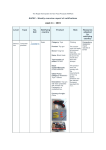
Table 1 - 4. Keyblock Module Descriptions
16 Keys
Catalog number: IC750KBL160
Keys: 16
LEDs: 16
Numeric (12 + 4 Keys)
Catalog number: IC750KBL400
Keys: 16
LEDs: 4
8 Keys
Catalog number: IC750KBL840
Keys: 8
LEDs: 4
Label fields: 1
1-8
PANELWARE Hardware Installation User’s Manual - June 1995
GFK-0848A
1
4 Keys
Catalog number: IC750KBL440
Keys: 4
LEDs: 4
Label fields: 4
Blank Module
Catalog number: IC750KBL000
Keys: None
LEDs: None
Emergency stop
Catalog number: IC750KBL910
EMERGENCY
STOP
2 normally closed high-current contacts
GFK-0848A
Chapter 1 System Overview
1-9
1
Key Switch
Catalog number: IC750KBL920
Key switch: 1
Key switch high current contacts: 1 normally
open and 1 normally closed
ON switch: normally open high-current
contact
OFF switch: normally closed high current
contact
Start/Stop
Catalog number: IC750KBL930
Keys: 2
Label fields: 1
1 normally open/1 normally closed highcurrent contact
The Emergency Stop, Key Switch, and Start/Stop modules are special modules that conform to
the same mechanical standards and design as all other PANELWARE modules. They cannot,
however, be connected electrically to other Keyblock modules or to the Panel Controller. They
must be connected to their respective functions by a qualified electrician. The Blank Module falls
in a separate class altogether, as it has no electrical connections whatsoever.
1 - 10
PANELWARE Hardware Installation User’s Manual - June 1995
GFK-0848A
1
Panel Controllers
Table 1 - 5. Basic (C200) Panel Controller Description
Basic Panel Controller (C200)
Catalog number: IC750CTR200
Interfaces:
RS-422/485
RS-232
RS-232
Programming software: PANELWARE Configuration Software (PCS)
GFK-0848A
Chapter 1 System Overview
1 - 11
1
Table 1 - 6. Genius (C400) Panel Controller Description
C400 Panel Controller
Catalog number: IC750CTR400
Interfaces:
RS-232
GENIUS
Programming software: PANELWARE Configuration Software (PCS)
1 - 12
PANELWARE Hardware Installation User’s Manual - June 1995
GFK-0848A
1
PANELWARE Operator Panel Hook-up
Panel to PLC
Panels with Controller C200 or C400 can be linked directly to a PLC, as shown below.
Figure 1 - 3. PANELWARE Panel Connection to PLC
GFK-0848A
Chapter 1 System Overview
1 - 13
1
Programming PANELWARE Operator Panels
The complete visualization and management of Keyblock functionality is handled by the Panel
Controller. A program is created using PCS running on a PC, then transferred to the Panel. This
program takes care of the PLC data exchange (data is written to or read from the PLC) to the
display and from the keys.
Note
For information on loading and running PCS, see the PANELWARE
Configuration Software Reference Manual (GFK-0849). For information
specific to the Genius (C400) Panel Controller, refer to the PANELWARE™
MMI Application Manual for GE Fanuc Genius™ Protocol User’s Manual
(GFK-1115).
1 - 14
PANELWARE Hardware Installation User’s Manual - June 1995
GFK-0848A
1
Ordering Information
Table 1 - 7. Product Catalog Numbers
Product
Catalog Number
Display Modules
Display Module 2 x 20 LCD
IC750LCD220
Display Module 4 x 20 LCD
IC750LCD420
Display Module 4 x 40 LCD
IC750LCD440
Display Module 8 x 40 LCD
IC750CFL840
Display Module 2 x 20 VFD
IC750VFD220
Display Module 2 x 40 VFD
IC750VFD240
Keyblock Modules
Keyblock Module - 16 keys
IC750KBL160
Keyblock Module - Numeric (12 + 4 keys)
IC750KBL400
Keyblock Module - 8 keys
IC750KBL840
Keyblock Module - 4 keys
IC750KBL440
Keyblock Module - Blank module
IC750KBL000
Keyblock Module - Emergency Stop - key
IC750KBL910
Keyblock Module - Key switch
IC750KBL920
Keyblock Module - Start/Stop
IC750KBL930
Panel Controllers
Basic Panel Controller, C200
IC750CTR200
Genius Panel Controller, C400
IC750CTR400
Accessories
Accessories set (spare parts kit)
IC750ACC004
Lithium battery (RENATA CR2477N)
IC750ACC002
Label sheets
IC750ACC005
Mounting bezel, 2X3 configuration
Mounting bezel, 2X2 configuration
IC750ACC230
RS-232 serial cable (with 25-pin to 9-pin adapter)
IC750CBL002
RS-422 serial cable
IC750CBL001
IC750ACC220
The components that are delivered with each module are listed in the corresponding chapters in
this manual (“Display Modules,” “Keyblock Modules,” “Panel Controllers,” and “Accessories”).
GFK-0848A
Chapter 1 System Overview
1 - 15
Chapter
Assembling System Components
2
This chapter describes how to assemble PANELWARE system components to suit the required
application. Illustrated, easy-to-follow steps are provided, as well as general information on
system components and maintenance. (In addition to the general information provided in this
chapter, please refer to installation instruction sheets that are packaged with some individual
components.)
■
■
■
GFK-0848A
General Information
2-2
❏
Tools Required for Assembly
2-2
❏
Component Descriptions
2-2
❏
Assembly Tips
2-3
❏
NEMA 12 and IP54 Ratings
2-4
❏
Cleaning the Display and Keys
2-4
❏
Power Connection and Grounding Recommendations
2-4
❏
Panel Configurations
2-4
Installation Options
2-5
❏
Cutout Dimensions and Installation
2-5
❏
Mounting Bezels
2-6
Package Contents
2-9
❏
Display Module Type 1 (20 Character)
2-9
❏
Display Module Type 2 (40 Character)
2-9
❏
Standard Keyblock Modules
2-10
❏
Special Keyblock Modules
2-10
❏
Panel Controllers
2-11
■
Keyblock Label Insertion/Exchange
2-12
■
Installation Procedure
2-15
❏
Panel Assembly
2-15
❏
Panel Installation
2-19
■
Panel Removal
2-21
■
Panel Disassembly
2-23
■
Controller Battery Installation/Replacement
2-26
2-1
2
General Information
Tools Required for Assembly
Each PANELWARE Operator Panel module (Display, Keyblock or Panel Controller) is shipped
with all components and accessories necessary for assembly. The following tools (not provided)
are required for assembly and maintenance of the Panel:
■
1 Phillips-head screwdriver (#1 size)
■
1 small, flat-head screwdriver
Component Descriptions
Each of the components/accessories required to connect and install PANELWARE modules is
described briefly below.
2-2
■
Purple plastic mounting pins that resemble keys are inserted at an angle (with the tab
fitting into the corner of the hole) in the corners of modules, then turned to the left or
right to lock into place. These are used to mount the spring clips.
■
A 1-inch ribbon cable (30-pin) connects the Panel Controller to the Display module.
Small tabs in the middle of each connector must be aligned (tabs up) for insertion.
■
Purple plastic spring clips are fastened around the edges of the installed Panel to snug it
up to the cutout or mounting bezel.
■
Short Keyblock cables with telephone-type connectors on each end connect Keyblock
modules to each other and to the Panel Controller, input to output. These cables are held
in place by cable covers once they are installed. A longer Keyblock cable is provided with
each Controller unit.
■
Module connectors are placed between Keyblock modules when a multi-Keyblock
configuration is created to connect the units to one another.
■
Purple plastic cable covers (approximately 1.5 inches long) are snapped into place over
Keyblock cables to keep them in place.
■
A termination resistor (with one telephone-type connector) is plugged into the output of
the last Keyblock module.
■
A lithium battery allows the Controller to store data such as historical alarm lists. A
battery cover on the back of the Controller lifts off to provide access to the housed
battery.
■
A tube of sealant (with application nozzle and squeezing tool) is provided to install the
assembled Panel into a cutout or ungasketed mounting bezel (this sealant must be used
to maintain the NEMA 12 and IP54 ratings).
■
Paper Keyblock label sheets are written on and inserted into each Keyblock module to
indicate programmed key functions. A blank label sheet comes pre-installed in every
Keyblock module; extras are provided with each Controller and can be ordered
separately.
■
Four metal screws are provided for attaching the Controller (Phillips #1).
PANELWARE Hardware Installation User’s Manual - June 1995
GFK-0848A
2
Assembly Tips
The following assembly tips and comments should make Panel assembly and installation easier:
Caution
Failure to observe these assembly tips may result in damaged equipment
and/or additional assembly time.
Caution
Handle plastic parts gently; using force may cause plastic to break.
GFK-0848A
■
Insert and remove the ribbon cable carefully. Do not use a screwdriver or other metal
object to remove the cable as this could strip insulation off of the wires.
■
When applying sealant, observe the following guidelines:
❏
Use sealant in a well ventilated area; do not inhale vapors for prolonged periods.
❏
Make sure the mounting surface is clean and free of grease.
❏
Remove sealant cap and attach the application nozzle, then use the squeezing tool (if
necessary) to expel sealant.
❏
Applied sealant requires approximately 2 hours at room temperature to cure.
❏
Squeeze out a thin line of sealant and try not to create clumps. If too much sealant is
applied, it may ooze onto front of unit.
❏
If applying sealant around the mounting bezel, take care not to place sealant too
close to the spring clips. Place the sealant around each mounting bolt as well.
❏
If you are using a gasket around the mounting bezel, do not use sealant on the gasket
or the bezel.
❏
To remove sealant, rub/lift it off with a spatula, a rag, or paper. Wash off any residue
using benzene or a similar solvent.
■
Write on and insert Keyblock labels prior to unit assembly if functions are programmed.
■
The metal Controller screws self-tap into plastic and can only be inserted and removed a
limited number of times before the plastic will begin to lose grip.
■
Insert mounting pins at an angle, lining up the pin tab with the groove in the insertion
point.
■
Set the Panel Controller number switch settings (operating mode) before installing the
unit into the cutout. If possible, leave enough room to access these settings with a
screwdriver after installation.
■
Units should not be permanently installed until programming has been completed.
■
Make sure all cable connections and any other protrusions are tucked inside the Panel,
flush against the unit, before installing in a cutout or mounting bezel.
Chapter 2 Assembling System Components
2-3
2
NEMA 12 and IP54 Ratings
All PANELWARE Operator Panels are rated for NEMA 12 and IP54 operation once they are
properly sealed and mounted in a Panel/cutout.
■
A NEMA 12 rating indicates that the enclosure provides a degree of protection against
dust, falling dirt, and dripping non-corrosive liquids. It is designed to meet drip, dust,
and rust-resistance tests.
■
An IP54 rating indicates that the enclosure is protected against dust (dust may not
interfere with operation) and splashing water.
These ratings are not guaranteed if the included sealant is not used to install the Panel.
Power Connection and Grounding Recommendations
The 24 VDC power connector on the Controller is located on the top left corner of the unit. It is
an orange 4-pin connector.
Caution
Do not try to run PANELWARE off a Series 90-30 power supply revision M
or earlier. Although some configurations might function under this setup, it
is not recommended. Damage to the 90-30 power supply could result.
The suitability of a Series 90-30, revision N or later power supply depends
on the +24VDC isolated load requirements of the modules in your PLC.
Refer to the Series 90-30 Programmable Controller I/O Module
Specifications (GFK-0898) to determine additional load requirements of
your system.
All components of a PLC and the devices it is controlling must be properly grounded. This is
particularly important for the reasons listed below:
■
A low-resistance path from all parts of a system to earth ground minimizes exposure to
shock in the event of short circuits or equipment malfunction.
■
PANELWARE Operator Panels require proper grounding for correct operation.
The importance of grounding can not be over emphasized.
Panel Configurations
When you are laying out the configuration for a Panel, keep in mind that the unit must be
rectangular in shape. Any empty spaces must be filled by blank Keyblock modules.
Configurations that include special modules can not be mounted in a 2 X 2 mounting bezel. In
addition, because of their depth, some special Keyblocks will only work in a few of the possible
Keyblock locations.
Cleaning the Display and Keys
To keep the display and Keyblocks free from dust and smudges, simply wipe them down gently
using a damp, soft cloth.
2-4
PANELWARE Hardware Installation User’s Manual - June 1995
GFK-0848A
2
Installation Options
Once a Panel unit is assembled, it can be installed either directly into a precisely cut out opening
in a panel, or into a mounting bezel that is then installed in the cutout (certain configurations
only). These pre-cut bezels are available as an accessory and provide the benefit of allowing a less
precise cutout to suffice for installation.
The following sections outline the two installation options.
Cutout Dimensions and Installation
The cutouts that will house the operator Panels must be precision-cut rectangles with tolerances of
-0; +0.5mm per dimension.
Cutout size should be calculated as follows:
Dimension (mm) = 96 * number of blocks - 4mm (-0; +0.5mm tolerance/dimension)
Table 2 - 1. Product and Cutout Dimensions
1)
GFK-0848A
Matrix Size
Product Dimensions
Cutout Dimensions 1)
1
96 mm/3.78 inch
92 mm/3.63 inch
2
192 mm/7.56 inch
188 mm/7.41 inch
3
288 mm/11.34 inch
284 mm/11.19 inch
4
384 mm/15.12 inch
380 mm/14.97 inch
Tolerances:
-0 mm +0.5 mm
(0 inch + 0.02 inch)
Chapter 2 Assembling System Components
2-5
2
The following figure shows an example cutout for a 2 X 3 operator Panel.
Figure 2 - 1. Cutout Example for a 2 X 3 Panel
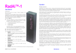
Mounting Bezels
A pre-cut, stainless steel mounting bezel can be used for installing two specific configurations of
PANELWARE Panels — units that are 2 X 3 (2 high by 3 wide) and units that are 2 X 2 (2 high
by 2 wide). Each bezel has mounting bolts welded to it and the remaining installation hardware
(captive locking washers and nuts) is provided as well.
The mounting bezel can be installed in a less precise cut, making Panel installation simpler and
less costly. The assembled Panel is sealed into the bezel, then the entire unit is installed and
sealed into the system cutout.
Note
If you are using a gasket on the bezel, do not apply sealant to either the gasket or
the bezel.
The 2 X 3 bezel can be ordered using catalog number IC750ACC230; the 2 X 2 bezel can be
ordered using order number IC750ACC220. See chapter 6, “Accessories” for more information.
The mounting bezel's dimensions and cutout information are provided in figures 2-2 and 2-3:
2-6
PANELWARE Hardware Installation User’s Manual - June 1995
GFK-0848A
2
9.65
(245MM)
10.39 .02
(264 .51MM)
.25 .10
(6.3 2.5MM)
(TYP. OTHER SIDE)
MOUNTING
HOLE PATTERN
9.65
(245MM)
.281 DIA. HOLES (4)
(CLEARANCE FOR M5 WELD STUDS)
.37 .10
(9.4 2.5MM)
(TYP. TOP EDGE)
10.15 .02
(258 .51MM)
44B714638-002R01
CUSTOMER CUTOUT
9.65" X 9.65"
(245MM X 245MM)
11.02
(280MM)
PANELWARE
10.78
(274MM)
MOUNTING PLATE
M5 STUD
CUSTOMER
MOUNTING
PANEL
CONNECTORS
Figure 2 - 2. Mounting Bezel Configuration - 2 X 2 Bezel
GFK-0848A
Chapter 2 Assembling System Components
2-7
2
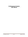
13.44
(341MM)
10.39 .02
(264 .51MM)
.25 .10
(6.3 2.5MM)
(TYP. OTHER SIDE)
MOUNTING
HOLE PATTERN
6.97 .02
(177 .51MM)
9.65
(245MM)
.281 DIA. HOLES (6)
(CLEARANCE FOR M5 WELD STUDS)
.37 .10
(9.4 2.5MM)
(TYP. TOP EDGE)
13.94 .02
(354 .51MM)
CUSTOMER CUTOUT
13.39" X 9.65"
(340MM X 245MM)
44B714638-001R01
11.02
(280MM)
PANELWARE
14.57
(370MM)
MOUNTING PLATE
M5 STUD
CUSTOMER
MOUNTING
PANEL
CONNECTORS
Figure 2 - 3. Mounting Bezel Configuration - 2 X 3 Bezel
2-8
PANELWARE Hardware Installation User’s Manual - June 1995
GFK-0848A
2
Package Contents
Display Module Type 1 (20 Character)
a
Mounting pins
b
Ribbon cable
c
Spring clips
a
Mounting pins
b
Ribbon cable
c
Spring clips
Display Module Type 2 (40 Character)
GFK-0848A
Chapter 2 Assembling System Components
2-9
2
Standard Keyblock Modules
a
Mounting pins
b
Short Keyblock cable
c
Spring clips
d
Module connectors
e
Cable covers
a
Mounting pins
b
Spring clips
c
Module connectors
d
Cable covers
Special Keyblock Modules
2 - 10
PANELWARE Hardware Installation User’s Manual - June 1995
GFK-0848A
2
Panel Controllers
Please refer to the instruction sheet that is packaged with your Panel Controller for detailed
installation instructions. (The C200 Controller is shown in the figure below.)
GFK-0848A
Chapter 2 Assembling System Components
a
Termination resistor
b
Screws
c
Battery
d
Sealant, application
nozzle and squeezing
tool
e
Keyblock label sheets
f
Long Keyblock cable
g
Power connector
h
Genius connector (not
shown — C400
Controller only)
2 - 11
2
Keyblock Label Insertion/Exchange
The following procedure is for use on an uninstalled Keyblock module. To change the label in an
installed Panel Keyblock module, the entire unit may need to be disassembled. You may, however,
be able to remove the Controller and the cable covers, then continue with the following procedure.
Remove mounting
pins (if desired) by
turning each pin to the
middle and pulling up
(this is not necessary,
but sometimes makes
the process easier)/
Gently turn both screw
locks to the OPEN
position as shown using
a small flathead
screwdriver.
2 - 12
PANELWARE Hardware Installation User’s Manual - June 1995
GFK-0848A
2
a
Press corner locks
inward using a
small, flathead
screwdriver or your
finger.
b
Remove the module
bottom by lifting out
and up.
Insert/exchange the
printed label sheet,
making sure the label
alignment matches the
Keyblock layout, and the
key function labels are
visible through the keys.
GFK-0848A
Chapter 2 Assembling System Components
2 - 13
2
Carefully replace the
bottom (position tabs
into tab slots on the top)
by pressing in on the
corner locks and gently
pushing until bottom
snaps into place.
Gently turn screw locks
to the CLOSE position
as shown and replace
any mounting pins (if
they were removed).
2 - 14
PANELWARE Hardware Installation User’s Manual - June 1995
GFK-0848A
2
Installation Procedure
Panel Assembly
Place Keyblock and
Display modules upside
down in the desired
positions on a soft,
relatively flat surface,
making sure to fit
beveled edges together.
The diagonal lines
should line up from
module to module.
GFK-0848A
Chapter 2 Assembling System Components
2 - 15
2
Insert the module
connectors between
the modules as
shown and press
firmly into place.
Note:
Two of the module
connectors have
one flat end and
one triangularshaped end; the
third connector has
two triangularshaped ends. Make
sure the flat ends of
the connectors are
located at the edges
of the Panel, and
the triangular
edges meet each
other in the middle.
Connect Keyblock
cables for the top
right module as
shown (clips should
point down and
away) by pushing in
until they snap into
place. The output
from this module
should be left
unattached to
connect to the Panel
Controller later.
2 - 16
PANELWARE Hardware Installation User’s Manual - June 1995
GFK-0848A
2
a
Connect all
Keyblock modules.
b
Use care to connect
inputs to outputs and
vice versa (see
triangular markings).
c
Insert termination
resistor into the
output of the last
Keyblock module.
d
Insert cable covers as
shown by lining up
the tabs in the
middle and gently
adjusting until they
snap into place.
Set Controller in
place, making sure
the ribbon cable
connectors from the
Controller and the
display are aligned
atop one another.
Note:
If possible, set
number switch
settings at this time,
before the unit is
installed in a Panel.
Note:
Your Controller may
have different
dimensions from the
model shown.
GFK-0848A
Chapter 2 Assembling System Components
2 - 17
2
a
Align mounting
holes and screw
Controller into place
using the 4 mounting
screws.
b
Connect the top right
Keyblock output
cable to Controller.
c
Gently connect
ribbon cable as
shown, aligning tabs.
Caution
Do not use anything
that might fray or
put pressure on the
ribbon cable when
connecting it. Your
fingers will work
best.
Note
After assembly, the termination resistor connector and the Keyblock cables
should not extend beyond the outer edges of the unit.
Once the Panel is assembled, 24V power can be connected.
2 - 18
PANELWARE Hardware Installation User’s Manual - June 1995
GFK-0848A
2
Panel Installation
Insert mounting pins at
corners as shown,
inserting key tabs into
slots at an angle in the
middle, then turning the
pins to the right or left to
lock.
Note:
Your Controller may
have different
dimensions from the
model shown.
Attach application
nozzle to the sealant
tube, then apply a thin
line of sealant around
the edges of the
assembled Panel (the
outer edge is about 1/8
inch deep). Be sure to
apply sealant only on the
outer edge.
GFK-0848A
Chapter 2 Assembling System Components
2 - 19
2
Quickly install Panel
in cutout or bezel
location (see
“Installation
Options” in this
chapter) by pushing
Panel through the
front of the cutout or
bezel and pressing
on edges to make a
seal.
Note:
Sealant curing time
is 2 hours at room
temperature.
a
Install spring clips
around edges of unit
as shown by aligning
grooves with tabs
and pushing until the
clips snap into place.
b
If the Panel is
mounted in a bezel,
apply sealant around
the outer edges and
bolts, then bolt the
entire assembly into
the cutout.
Note:
If a gasket is placed
between the bezel
and the cutout, do
not apply sealant to
either the gasket or
the bezel.
c
2 - 20
PANELWARE Hardware Installation User’s Manual - June 1995
Connect 24 V power
to the unit.
GFK-0848A
2
Panel Removal
Carefully remove spring
clips by pulling out with
fingers or prying loose
using a small
screwdriver.
Caution
Take care not to break
plastic parts during
Panel removal.
Remove Panel from
cutout location or bezel
by pushing firmly on the
back of unit and gently
prying up the sealed
edges.
Note:
If the Panel is installed
in a bezel, the mounting
bezel may need to be
removed from the cutout
as described above.
GFK-0848A
Chapter 2 Assembling System Components
2 - 21
2
DO NOT remove
mounting pins.
Before reinstalling the
Panel, remove remaining
sealant from around
Panel and cutout (or
bezel) edges using a
spatula, a rag, or paper.
Note:
Remember to apply new
sealant before
reinstalling the unit.
2 - 22
PANELWARE Hardware Installation User’s Manual - June 1995
GFK-0848A
2
Panel Disassembly
Caution
Use extreme care when removing plastic parts. Plastic may break if force is
used.
a
Disconnect ribbon
cable carefully by
gently prying it
loose.
Caution
When disconnecting
the ribbon cable, do
not use anything
metal that might fray
or put pressure on it.
b
Disconnect Keyblock
cable from
Controller using a
small flathead
screwdriver to pry
tab up.
c
Remove the four
Controller mounting
screws.
Note:
Your Controller may
have different
dimensions from the
model shown.
GFK-0848A
Chapter 2 Assembling System Components
2 - 23
2
Remove Controller and
set aside.
Note:
The metal Controller
screws self-tap into
plastic and can only be
removed a limited
number of times before
the plastic will begin to
lose grip.
Remove cable covers
using a small flathead
screwdriver to pry them
loose.
2 - 24
PANELWARE Hardware Installation User’s Manual - June 1995
GFK-0848A
2
Disconnect and remove
remaining Keyblock
cables and the
termination resistor
using a small flathead
screwdriver to pry tabs
up.
Remove module
connectors using a small
flathead screwdriver to
pry them up.
GFK-0848A
Chapter 2 Assembling System Components
2 - 25
2
Controller Battery Installation/Replacement
Each Controller is delivered with a lithium battery in a plastic bag inside the box. This battery
should be installed before unit operation and replaced every two years (or as needed).
Remove the battery
cover on the back of the
Controller by inserting a
fingernail into the slot
and pushing back to lift
cover off.
Install/exchange battery
using fingers; do not
touch battery with a
conductive device.
Use the following
battery type.
RENATA CR2477N;
GE catalog number
IC750ACC002.
Note:
Dispose of old battery in
accordance with the
MSDS sheet provided.
2 - 26
PANELWARE Hardware Installation User’s Manual - June 1995
GFK-0848A
Chapter
Display Modules: Overview
3
This chapter describes the various PANELWARE Display Modules and explains how to connect
them. It provides the following information:
■
■
■
■
GFK-0848A
General Information
3-2
❏
Backlight (LCD Displays Only)
3-2
❏
Contrast (LCD Displays Only)
3-2
❏
Connection to the Panel Controller
3-3
Display Modules with LCD Displays
3-4
❏
Display Module 2 x 20 LCD
3-4
❏
Display Module 4 x 20 LCD
3-5
❏
Display Module 4 x 40 LCD
3-6
❏
Display Module 8 x 40 LCD
3-7
Display Modules with VFD Displays
3-8
❏
Display Module 2 x 20 VFD
3-8
❏
Display Module 2 x 40 VFD
3-9
Accessories
3-10
3-1
3
General Information
Backlight (LCD Displays Only)
All LCD Display Modules are equipped with backlights as described below.
Table 3 - 1. Backlights on Display Modules
Display Module
Backlight
Color
Display Module 2 x 20 LCD;
2 x 40 LCD; 4 x 40 LCD
LED-Back Lit
Black on yellow
Display Module 8 x 40 LCD
CFL-Back Lit
Black on white
Contrast (LCD Displays Only)
All LCD Display Modules are equipped
with a potentiometer for adjusting screen
contrast. The contrast adjustment is located
on the top of the module (see view A). For
best results, contrast adjustments should be
made after the display has warmed up but
before the display is mounted in a unit.
Turn the potentiometer gently.
Caution
Use a very small
Phillips-head
screwdriver to adjust the
potentiometer. Do not
push on the
potentiometer because it
may come loose from the
board.
Figure 3 - 1. Display Module Contrast Control
3-2
PANELWARE Hardware Installation User’s Manual - June 1995
GFK-0848A
3
Connection to the Panel Controller
A connector on the top right-hand side of the module allows connection to the Panel Controller
(see view B). A ribbon cable is delivered with every Display Module.
Caution
You must use the ribbon cable provided. Do not try to use a longer, different
ribbon cable.
Figure 3 - 2. Display Module Connection to Panel Controller
Caution
During operation, do not disconnect the ribbon cable that connects the
Display Module to the Panel Controller. When connecting or disconnecting
the ribbon cable, do not use anything that might fray or put pressure on the
cable.
Be sure power is off before connecting or disconnecting the ribbon cable.
GFK-0848A
Chapter 3 Display Modules: Overview
3-3
3
Display Modules with LCD Displays
Display Module 2 x 20 LCD
Figure 3 - 3. Display Module with 2 X 20 LCD
Table 3 - 2. Specifications for Display Module with 2 X 20 LCD
3-4
Catalog number
IC750LCD220
Display type
LCD
Lines x characters
2 x 20
Character height
5.0 mm (0.1969 inch)
Background lighting
LED
Color
black on yellow
Temperature
Operating
Storage
0 to 50 °C (32 to 122 °F)
-20 to 60 °C (-4 to 140 °F)
Relative humidity
Operating
Storage
10 to 90 % (non-condensing)
10 to 90 % (non-condensing)
Shock
conforms to IEC 68-2-27
15g equivalent, 150 m/sec2, 11 msec, 3 axes (positive and
negative)
Vibration
conforms to IEC 68-2-6
1g equivalent, 10-58 Hz; 0.075 mm
58-150 Hz; 9.8m/sec2
20 cycles per axis
24 VDC power
requirements
100 mA
Sealing
NEMA 12 and IP54, when properly mounted in a panel
Noise immunity
conforms to IEC 801.2; IEC 801.3; IEC 801.4
PANELWARE Hardware Installation User’s Manual - June 1995
GFK-0848A
3
Display Module 4 x 20 LCD
Figure 3 - 4. Display Module with 4 X 20 LCD
Table 3 - 3. Specifications for Display Module with 4 X 20 LCD
Catalog number
IC750LCD420
Display type
LCD
Lines x characters
4 x 20
Character height
8.0 mm (0.3150 inch)
Background lighting
LED
Color
black on yellow
Temperature
Operating
Storage
0 to 50 °C (32 to 122 °F)
-20 to 60 °C (-4 to 140 °F)
Relative humidity
Operating
Storage
10 to 90 % (non-condensing)
10 to 90 % (non-condensing)
Shock
conforms to IEC 68-2-27
15g equivalent, 150 m/sec 11 msec, 3 axes (positive and negative)
Vibration
conforms to IEC 68-2-6
1g equivalent, 10-58 Hz; 0.075 mm
58-150 Hz; 9.8m/sec2
20 cycles per axis
24 VDC power
requirements
200 mA
Sealing
NEMA 12 and IP54, when properly mounted in a panel
Noise immunity
conforms to IEC 801.2; IEC 801.3; IEC 801.4
Note
If the front panel of the display is touched immediately after power-up, black
lines may appear on the display temporarily. This effect is minimal after the
display has warmed up.
GFK-0848A
Chapter 3 Display Modules: Overview
3-5
3
Display Module 4 x 40 LCD
Figure 3 - 5. Display Module with 4 X 40 LCD
Table 3 - 4. Specifications for Display Module with 4 X 40 LCD
3-6
Catalog number
IC750LCD440
Display type
LCD
Lines x characters
4 x 40
Character height
4.3 mm (0.1693 inch)
Background lighting
LED
Color
black on yellow
Temperature
Operating
Storage
0 to 50 °C (32 to 122 °F)
-20 to 60 °C (-4 to 140 °F)
Relative humidity
Operating
Storage
10 to 90 % (non-condensing)
10 to 90 % (non-condensing)
Shock
conforms to IEC 68-2-27
15g equivalent, 150 m/sec2, 11 msec, 3 axes (positive and
negative)
Vibration
conforms to IEC 68-2-6
1g equivalent, 10-58 Hz; 0.075 mm
58-150 Hz; 9.8m/sec2
20 cycles per axis
24 VDC power
requirements
250 mA
Sealing
NEMA 12 and IP54, when properly mounted in a panel
Noise immunity
conforms to IEC 801.2; IEC 801.3; IEC 801.4
PANELWARE Hardware Installation User’s Manual - June 1995
GFK-0848A
3
Display Module 8 x 40 LCD
96 mm (3.780 inch)
a45455
288 mm (11.339 inch)
35 mm
(1.378 inch)
Figure 3 - 6. Display Module with 8 X 40 LCD
Table 3 - 5. Specifications for Display Module with 8 X 40 LCD
GFK-0848A
Catalog number
IC750CFL840
Display type
LCD, graphics capable
Lines x characters
8 x 40
Pixel Resolution
64 vertical x 240 horizontal (Each character cell consists of 8 x 6 pixels.)
Character height
4.0 mm (0.1575 inch)
Character sizes
single, double and quadruple size
Background lighting
CFL (miniature fluorescent lamp)
Color
black on white
Temperature
Operating
Storage
0 to 50 °C (32 to 122 °F)
-20 to 60 °C (-4 to 140 °F)
Relative humidity
Operating
Storage
10 to 90 % (non-condensing)
10 to 90 % (non-condensing)
Shock
conforms to IEC 68-2-27
15g equivalent, 150 m/sec2, 11 msec, 3 axes (positive and
negative)
Vibration
conforms to IEC 68-2-6
1g equivalent, 10-58 Hz; 0.075 mm
58-150 Hz; 9.8m/sec2
20 cycles per axis
24 VDC power
requirements
200 mA
Sealing
NEMA 12 and IP54, when properly mounted in a panel
Noise immunity
conforms to IEC 801.2; IEC 801.3; IEC 801.4
Chapter 3 Display Modules: Overview
3-7
3
Display Modules with VFD Displays
Display Module 2 x 20 VFD
Figure 3 - 7. Display Module with 2 X 20 VFD
Table 3 - 6. Specifications for Display Module with 2 X 20 VFD
3-8
Catalog number
IC750VFD220
Display type
VFD
Lines x characters
2 x 20
Character height
5.0 mm (0.1969 inch)
Background lighting
none
Color
green (505 nm)
Temperature
Operating
Storage
0 to 50 °C (32 to 122 °F)
-20 to 60 °C (-4 to 140 °F)
Relative humidity
Operating
Storage
20 to 85 % (non-condensing)
20 to 90 % (non-condensing)
Shock
conforms to IEC 68-2-27
15g equivalent, 150 m/sec2, 11 msec, 3 axes (positive and
negative)
Vibration
conforms to IEC 68-2-6
1g equivalent, 10-58 Hz; 0.075 mm
58-150 Hz; 9.8m/sec2
20 cycles per axis
24 VDC power
requirements
200 mA
Sealing
NEMA 12 and IP54, when properly mounted in a panel
Noise immunity
conforms to IEC 801.2; IEC 801.3; IEC 801.4
PANELWARE Hardware Installation User’s Manual - June 1995
GFK-0848A
3
Display Module 2 x 40 VFD
Figure 3 - 8. Display Module with 2 X 40 VFD
Table 3 - 7. Specifications for Display Module with 2 X 40 VFD
GFK-0848A
Catalog number
IC750LCD240
Display type
VFD
Lines x characters
2 x 40
Character height
5.0 mm (0.1969 inch)
Background lighting
none
Color
green (505 nm)
Temperature
Operating
Storage
0 to 50 °C (32 to 122 °F)
-20 to 60 °C (-4 to 140 °F)
Relative humidity
Operating
Storage
20 to 85 % (non-condensing)
20 to 90 % (non-condensing)
Shock
conforms to IEC 68-2-27
15g equivalent, 150 m/sec2, 11 msec, 3 axes (positive and
negative)
Vibration
conforms to IEC 68-2-6
1g equivalent, 10-58 Hz; 0.075 mm
58-150 Hz; 9.8m/sec2
20 cycles per axis
24 VDC power
requirements
200 mA
Sealing
NEMA 12
Noise immunity
conforms to IEC 801.2; IEC 801.3; IEC 801.4
Chapter 3 Display Modules: Overview
3-9
3
Accessories
Accessory components are required for connecting and installing each Display Module. These
accessories are shipped in the same package as the Display Module in the quantities indicated
below.
Table 3 - 8. Display Module Accessory Components
Quantity
Accessory Components
1 x 2 Display
Ribbon cable (connects Display Module to Panel
Controller)
Spring clips
Mounting pins
3 - 10
1 x 3 Display
1
1
6
8
1 bag
1 bag
(4 small, 2 large) (4 small, 2 large)
Keyblock cables
N/A
N/A
Module connectors
N/A
N/A
PANELWARE Hardware Installation User’s Manual - June 1995
GFK-0848A
Chapter
Keyblock Modules
4
This chapter explains how to connect the various Keyblock modules to each other and to the Panel
Controller in order to create the desired unit. It contains the following information:
■
■
■
■
GFK-0848A
General Information ...................................................................................................4-2
❏
Dimensions..........................................................................................................4-2
❏
Standard and Special Keyblock Modules..............................................................4-3
❏
Keyblock Labels...................................................................................................4-3
❏
Keyblock Cables ..................................................................................................4-4
Standard Keyblock Modules .......................................................................................4-5
❏
Connection to Panel Controller or to Other Keyblock Modules.............................4-5
❏
Keyblock Module 16 Keys ...................................................................................4-7
❏
Keyblock Module Numeric (12+4 Keys) ..............................................................4-8
❏
Keyblock Module 8 Keys .....................................................................................4-9
❏
Keyblock Module 4 Keys ...................................................................................4-10
Special Modules .......................................................................................................4-11
❏
Blank Module ....................................................................................................4-11
❏
Emergency Stop Switch .....................................................................................4-12
❏
Key Switch ........................................................................................................4-13
❏
Start/Stop........................................................................................................... 4-15
Accessories...............................................................................................................4-16
4-1
4
General Information
Dimensions
All standard Keyblock modules (and some special modules) have the following (identical)
dimensions, regardless of the number/layout of the keys:
Figure 4 - 1. Keyblock Module Dimensions
4-2
PANELWARE Hardware Installation User’s Manual - June 1995
GFK-0848A
4
Standard and Special Keyblock Modules
Keyblock modules provide keys that are pressed to activate the panel's individual programmed
functions. Removable label sheets allow each key to be identified by a name or an icon. If a key
has an associated LED, the LED is located in the top left corner.
Keyblock modules are divided into two categories:
■
Up to seven Standard Keyblock Modules can be cascaded and connected to a Panel
Controller.
■
Special Keyblock Modules are identical in design (and sometimes dimension) to the
standard Keyblock modules. They cannot, however, be connected electrically to a Panel
Controller or a standard Keyblock module. Special modules must be connected to their
respective functions by a qualified electrician (e.g., linking the Emergency Stop switch to
the emergency stop security chain).
All panel configurations must be rectangular in shape. Any empty spaces must be filled by blank
Keyblock modules.
Note
Configurations that include special modules can not be mounted in a 2 X 2
configuration. In addition, some special Keyblocks will only work in a few
physical locations because of their depth. See the descriptions that follow.
Caution
Do not press Keyblock keys with a sharp or pointed object.
Keyblock Labels
Keyblock modules can perform different application functions depending on how the key
assignments are programmed. Removable sheets allow you to switch key labels whenever you
change the panel program. A separate label sheet can be used for each application, with individual
key functions written or typed on the corresponding key template. Each label sheet consists of six
perforated legend layouts with triangular cutouts that allow an LED to show through on the
Keyblock. Each Keyblock module is shipped with a blank label sheet already in place.
Label sheets come in two sizes—A4 and US letter (8.5 inches X 11 inches). See chapter 6 for
information on ordering additional label sheets.
To remove an individual label from a label sheet, locate one of the six perforated squares and tear
gently along the perforated lines. Write (using non-smearing ink) or type the desired key functions
or identifying icons on the corresponding keys (you may wish to create a word processing template
for this function), making sure the writing will be clearly visible from behind the plastic key
cover.
Gently insert the label behind the plastic Keyblock cover in the orientation that matches the
Keyblock layout. For more instructions on removing or inserting labels, see chapter 2.
GFK-0848A
Chapter 4 Keyblock Modules
4-3
4
Keyblock Cables
Each Keyblock module is shipped with a short Keyblock cable for connecting it to either the
Controller or another Keyblock module. The short cable’s length is that required to connect one
Keyblock module to another when they are side by side.
To accommodate Keyblock configurations that require a longer cable (e.g., two Keyblock modules
separated by a blank module), each Controller is shipped with a long (230 mm) Keyblock cable.
You may or may not need to use this cable.
4-4
PANELWARE Hardware Installation User’s Manual - June 1995
GFK-0848A
4
Standard Keyblock Modules
Connection to Panel Controller or Another Keyblock Module
Standard Keyblock modules are connected to the Panel Controller or to another Keyblock module
using the cable(s) provided (maximum length is 230mm), as shown in figure 4-2. Two telephone
connectors on each module (figure 4-3, view A) are indicated as input or output (see view B). An
output on the Controller must be connected to an input of a Keyblock module, and so forth. A
termination resistor must be plugged into the output connection of the last Keyblock module in the
chain.
Warning
Do not connect a Keyblock module input to another Keyblock module input
or an output to another output.
Caution
The use of custom length cables is not encouraged. If custom cables are
used, their total connection length should not exceed 230 mm.
Figure 4 - 2. Keyblock Module Connection Schematic
GFK-0848A
Chapter 4 Keyblock Modules
4-5
4
Figure 4 - 3. Keyblock Module Connection Details
4-6
PANELWARE Hardware Installation User’s Manual - June 1995
GFK-0848A
4
Keyblock Module 16 Keys
Figure 4 - 4. Keyblock Module with 16 Keys
Table 4 - 1. Specifications for Keyblock Module with 16 Keys
GFK-0848A
Catalog number
IC750KBL160
Number of keys
16 short-stroke keys
Number of LEDs
16 (yellow)
Labeling
label strips are provided for creating application-specific key labels
Temperature
Operating
Storage
0 to 50 °C (32 to 122 °F)
-20 to 60 °C (-4 to 140 °F)
Relative humidity
Operating
Storage
5 to 95 % (non-condensing)
5 to 95 % (non-condensing)
Shock
conforms to IEC 68-2-27
15g equivalent, 150 m/sec2, 11 msec, 3 axes (positive and
negative)
Vibration
conforms to IEC 68-2-6
1g equivalent, 10-58 Hz; 0.075 mm
58-150 Hz; 9.8m/sec2
20 cycles per axis
24 VDC power
requirements
50 mA
Sealing
NEMA 12 and IP54, when properly mounted in a panel
Noise immunity
conforms to IEC 801.2; IEC 801.3; IEC 801.4
Switch rating
rated for 1 million operations, minimum
Chapter 4 Keyblock Modules
4-7
4
Keyblock Module Numeric (12+4 Keys)
Figure 4 - 5. Keyblock Module Numeric (12+4 Keys)
Note
Your numeric Keyblock module may not have the E and C keys. Instead, the E
key (ENTER) may be the ↵ symbol and the C key (CLEAR) may be the ←
symbol.
Table 4 - 2. Specifications for Numeric Keyblock Module
4-8
Catalog number
IC750KBL400
Number of keys
16 short-stroke keys
Number of LEDs
4 (yellow)
Labeling
12 keys are labeled as a numeric block
4 keys can be labeled using the labels provided
Temperature
Operating
Storage
0 to 50 °C (32 to 122 °F)
-20 to 60 °C (-4 to 140 °F)
Relative humidity
Operating
Storage
5 to 95 % (non-condensing)
5 to 95 % (non-condensing)
Shock
conforms to IEC 68-2-27
15g equivalent, 150 m/sec2, 11 msec, 3 axes (positive and
negative)
Vibration
conforms to IEC 68-2-6
1g equivalent, 10-58 Hz; 0.075 mm
58-150 Hz; 9.8m/sec2
20 cycles per axis
24 VDC power
requirements
12 mA
Sealing
NEMA 12 and IP54, when mounted in a panel properly
Noise immunity
conforms to IEC 801.2; IEC 801.3; IEC 801.4
Switch rating
rated for 1 million operations, minimum
PANELWARE Hardware Installation User’s Manual - June 1995
GFK-0848A
4
Keyblock Module 8 Keys
Figure 4 - 6. Keyblock Module with 8 Keys
Table 4 - 3. Specifications for Keyblock Module with 8 Keys
Catalog number
IC750KBL840
Number of keys
8 short-stroke keys
Number of LEDs
4 (yellow)
Note: PANELWARE Configuration Software allows configuration of 8 LEDs for this
module. This capability is provided for future expansion.
GFK-0848A
Labeling
label strips are provided for creating application-specific key labels
Label fields
1 field for additional information
Temperature
Operating
Storage
0 to 50 °C (32 to 122 °F)
-20 to 60 °C (-4 to 140 °F)
Relative humidity
Operating
Storage
5 to 95 % (non-condensing)
5 to 95 % (non-condensing)
Shock
conforms to IEC 68-2-27
15g equivalent, 150 m/sec2, 11 msec, 3 axes (positive and
negative)
Vibration
conforms to IEC 68-2-6:
24 VDC power
requirements
12 mA
Sealing
NEMA 12 and IP54, when mounted in a panel properly
Noise Immunity
conforms to IEC 801.2; IEC 801.3; IEC 801.4
Switch rating
rated for 1 million operations, minimum
Chapter 4 Keyblock Modules
1g equivalent, 10-58 Hz; 0.075 mm
58-150 Hz; 9.8m/sec2
20 cycles per axis
4-9
4
Keyblock Module 4 Keys
Figure 4 - 7. Keyblock Module with 4 Keys
Table 4 - 4. Specifications for Keyblock Module with 4 Keys
4 - 10
Catalog number
IC750KBL440
Number of keys
4 short-stroke keys
Number of LEDs
4 (yellow)
Labeling
label strips are provided for creating application-specific key labels
Label fields
4 fields for additional information
Temperature
Operating
Storage
0 to 50 °C (32 to 122 °F)
-20 to 60 °C (-4 to 140 °F)
Relative humidity
Operating
Storage
5 to 95 % (non-condensing)
5 to 95 % (non-condensing)
Shock
conforms to IEC 68-2-27
15g equivalent, 150 m/sec2, 11 msec, 3 axes (positive and
negative)
Vibration
conforms to IEC 68-2-6
1g equivalent, 10-58 Hz; 0.075 mm
58-150 Hz; 9.8m/sec2
20 cycles per axis
24 VDC power
requirements
12 mA
Sealing
NEMA 12 and IP54, when mounted in a panel properly
Noise immunity
conforms to IEC 801.2; IEC 801.3; IEC 801.4
Switch rating
rated for 1 million operations, minimum
PANELWARE Hardware Installation User’s Manual - June 1995
GFK-0848A
4
Special Modules
Blank Module
Figure 4 - 8. Blank Keyblock Module
Table 4 - 5. Specifications for Blank Keyblock Module
GFK-0848A
Catalog number
IC750KBL000
Number of keys
none
Number of LEDs
none
Temperature
Operating
Storage
0 to 50 °C (32 to 122 °F)
-20 to 60 °C (-4 to 140 °F)
Relative humidity
Operating
Storage
5 to 95 % (non-condensing)
5 to 95 % (non-condensing)
Shock
conforms to IEC 68-2-27
15g equivalent, 150 m/sec2, 11 msec, 3 axes (positive and
negative)
Vibration
conforms to IEC 68-2-6
1g equivalent, 10-58 Hz; 0.075 mm
58-150 Hz; 9.8m/sec2
20 cycles per axis
Sealing
NEMA 12 and IP54, when mounted in a panel properly
Chapter 4 Keyblock Modules
4 - 11
4
Emergency Stop Switch
1.18"
(30 mm)
a45508
2.01"
(51 mm)
EMERGENCY
3.78"
(96 mm)
STOP
1.38"
35 mm)
3.78"
(96 mm)
Figure 4 - 9. Emergency Stop Switch Module
Caution
It is not possible to place a Controller directly behind this Keyblock module
due to the module's depth.
Table 4 - 6. Specifications for Emergency Stop Switch Module
4 - 12
Catalog number
IC750KBL910
Number of switches
1 EMERGENCY STOP switch
Temperature
Operating
Storage
0 to 50 °C (32 to 122 °F)
-20 to 60 °C (-4 to 140 °F)
Relative humidity
Operating
Storage
5 to 95 % (non-condensing)
5 to 95 % (non-condensing)
Shock
conforms to IEC 68-2-27
15g equivalent, 150 m/sec2, 11 msec, 3 axes (positive and
negative)
Vibration
conforms to IEC 68-2-6
1g equivalent, 10-58 Hz; 0.075 mm
58-150 Hz; 9.8m/sec2
20 cycles per axis
Contacts
2 X NORMALLY CLOSED
10 Amps @ 220 VAC; 7.5 Amps @ 380 VAC
Sealing
NEMA 12 and IP54, when mounted in a panel properly
Switch rating
rated for 1 million operations, minimum
PANELWARE Hardware Installation User’s Manual - June 1995
GFK-0848A
4
Key Switch Module
a45509
1.58"
(40 mm)
2.79"
(71 mm)
ON
3.78"
(96mm)
OFF
1.38"
(35 mm)
3.78"
(96mm)
Figure 4 - 10. Key Switch Module
Warning
Revision B and later Key Switch modules not interchangeable with revision
A Key Switch Modules. Because the type of OFF switch has been changed,
the two versions operate differently. If you replace an A version of the
module with a B or later version (or vice-versa), you must also modify your
system configuration accordingly before powering up.
Revision B
Revision A
OFF contacts are normally closed and open
momentarily when the OFF switch is pressed.
OFF contacts are normally open and close
momentarily when the OFF switch is pressed
Caution
It is not possible to place a Controller directly behind this Keyblock module
due to the module's depth.
GFK-0848A
Chapter 4 Keyblock Modules
4 - 13
4
Table 4 - 7. Specifications for Key Switch Module
Catalog number
IC750KBL920
Number of
switches
1 Key switch
1 ON/OFF switch
Temperature
Operating
Storage
0 to 50 °C (32 to 122 °F)
-20 to 60 °C (-4 to 140 °F)
Relative humidity
Operating
Storage
5 to 95 % (non-condensing)
5 to 95 % (non-condensing)
Shock
conforms to IEC 68-2-27
15g equivalent, 150 m/sec2, 11 msec, 3 axes (positive and negative)
Vibration
conforms to IEC 68-2-6
1g equivalent, 10-58 Hz; 0.075 mm
58-150 Hz; 9.8m/sec2
20 cycles per axis
Contacts
Key switch
ON switch
OFF switch
4 - 14
1- NORMALLY CLOSED, 1 - NORMALLY OPEN
10 amps @ 220 VAC; 7.5 amps @ 380 VAC
1 NORMALLY OPEN
10 amps @ 220 VAC; 7.5 amps @380 VAC
1 NORMALLY CLOSED (Revision B and later — see WARNING on page 4-13)
10 amps @ 220 VAC; 7.5 amps @ 380 VAC
Sealing
NEMA 12 and IP54, when mounted in a panel properly
Switch rating
rated for 1 million operations, minimum
PANELWARE Hardware Installation User’s Manual - June 1995
GFK-0848A
4
Start/Stop
.53"
(13.4 mm)
a45510
2.95"
(75 mm)
3.78"
(96mm)
STOP
1.38"
(35 mm)
START
3.78"
(96mm)
Figure 4 - 11. Start/Stop Module
Caution
It is not possible to place a Controller directly behind this Keyblock module
due to the module's depth.
Table 4 - 8. Specifications for Start/Stop Module
GFK-0848A
Catalog number
IC750KBL930
Number of keys
2 keys (labeled START and STOP)
Labeling
a label strip is provided for creating an application-specific key label
Label fields
1 field for additional information
Relative humidity
Operating
Storage
5 to 95 % (non-condensing)
5 to 95 % (non-condensing)
Shock
conforms to IEC 68-2-27
15g equivalent, 150 m/sec2, 11 msec, 3 axes (positive and
negative)
Vibration
conforms to IEC 68-2-6
1g equivalent, 10-58 Hz; 0.075 mm
58-150 Hz; 9.8m/sec2
20 cycles per axis
Contacts
1 - NORMALLY CLOSED, 1 - NORMALLY OPEN
10 Amps @ 220 VAC; 7.5 Amps @ 380 VAC
Sealing
NEMA 12 and IP54, when mounted in a panel properly
Noise immunity
conforms to IEC 801.2; IEC 801.3; IEC 801.4
Switch rating
rated for 1 million operations, minimum
Chapter 4 Keyblock Modules
4 - 15
4
Accessories/Replacement Components
Accessory components are required for connecting and installing each Keyblock module. The
accessories are shipped in the same package as the Keyblock module in the quantities indicated in
table 4-9. Table 4-10 lists ordering information for replacement lamps.
Table 4 - 9. Keyblock Module Accessory Components
Quantity
Standard
Keyblock
Modules
Special
Keyblock
Modules
Module connectors (one double-nosed and two single-nosed)
3
3
Cable covers
2
2
Short Keyblock cable (connects Panel Controller to Keyblock module, or
connects Keyblock module to Keyblock module)
1
----
Accessories
Spring clips
Mounting pins
2
2
1 bag
1 bag
Table 4 - 10. Replacement Lamps
4 - 16
Type
Catalog Number
24 — 30 VAC, 2 W, BA9S
RAFI 1.90060.133
110 — 130 VAC, 2 W, BA9S
RAFI 1.90060.137
PANELWARE Hardware Installation User’s Manual - June 1995
GFK-0848A
Chapter
Panel Controllers
5
Two Panel Controllers, C200 (basic) and C400 (Genius), are available for use with the
PANELWARE system. This chapter presents specifications, connections (interfaces) and
describes the hardware configuration for both units. The hardware information for the C400 Panel
Controller is duplicated, for your convenience, in the PANELWARE MMI Application Manual for
GE Fanuc Genius Protocol User's Manual (GFK 1115). Refer to GFK-1115 for additional
information about operating the PANELWARE system with Genius protocol. For other protocols,
refer to the appropriate Application Manual (listed in the “Preface”).
■
■
■
■
■
GFK-0848A
General Information ...................................................................................................5-2
❏
VDC Power Requirement.....................................................................................5-2
❏
Connecting Power to Controller...........................................................................5-2
❏
Setting Number Switches.....................................................................................5-2
Basic Panel Controller (C200) ....................................................................................5-3
❏
Specifications ......................................................................................................5-3
❏
Overview of Connections and Operational Elements ............................................5-4
Genius Panel Controller (C400)..................................................................................5-8
❏
Specifications ......................................................................................................5-8
❏
Overview of Connections and Operational Elements ............................................5-9
Operating the Panel Controllers................................................................................5-13
❏
FlashPROM.......................................................................................................5-13
❏
RESET Modes ...................................................................................................5-13
❏
Loading and Starting Panel Programs................................................................5-14
❏
Update Mode/Reloading the Operating System ..................................................5-15
Accessories...............................................................................................................5-15
5-1
5
General Information
24 VDC Power Requirement
+24 VDC power must be supplied to the PANELWARE Controller unit. The Controller, in turn,
supplies the Keyblock and Display modules with power.
When estimating the total +24 VDC power consumption for a system, add up the 24 VDC power
supply requirements for all of the PANELWARE components being used, then add an additional
30% to allow for power-on surge currents. Appendix C lists power requirements for
PANELWARE components.
Connecting Power to Controller
The 24 VDC power connector on the Controller is located on the top left corner of the unit. The
mating connector is supplied with each Controller.
Caution
Do not try to run PANELWARE off a Series 90-30 power supply revision M
or earlier. Although some configurations might function under this setup, it
is not recommended. Damage to the 90-30 power supply could result.
The suitability of a Series 90-30 revision N or later power supply depends on
the +24VDC isolated load requirements of the modules in your PLC. Refer
to the Series 90-30 Programmable Controller I/O Module Specifications
(GFK-0898) to determine additional load requirements of your system.
All components of a PLC and the devices it is controlling must be properly grounded. This is
particularly important for the reasons listed below:
■
A low-resistance path from all parts of a system to ground minimizes exposure to shock
in the event of short circuits or equipment malfunction.
■
PANELWARE Operator Panels require proper grounding for correct operation.
The importance of grounding can not be over emphasized.
Setting Number Switches
Number switch settings on the Panel Controller can be set using a small flathead screwdriver to
turn the switch dial to the desired setting (the arrow will point at the current setting).
The assembled Panel configuration provides minimal space to reach the number switches once the
Panel is installed. If possible, these settings should be made before the Controller is installed.
5-2
PANELWARE Hardware Installation User’s Manual - June 1995
GFK-0848A
5
Basic Panel Controller (C200)
Specifications
Figure 5 - 1. Basic Panel Controller (C200)
Table 5 - 1. Specifications for Basic Panel Controller (C200)
GFK-0848A
Catalog number
IC750CTR200
Interfaces
IF0:
IF1:
IF2:
Programming
PANELWARE Configuration Software
Power supply
24 VDC (min. 18 VDC, max. 30 VDC)
Real-time clock
YES with battery installed (non-volatile)
Connection of ...
Display modules
Keyblock modules
1
maximum of 7
Temperature
Operating
Storage
0 to 50 °C (32 to 122 °F)
-20 to 60 °C (-4 to 140 °F)
Relative humidity
Operating
Storage
10 to 95 % (non-condensing)
10 to 95 % (non-condensing)
Chapter 5 Panel Controllers
RS-232 (not galvanically isolated)
RS-232 (not galvanically isolated)
RS-422/RS-485 (galvanically isolated)
5-3
5
Table 5 - 1. - Continued
Shock
conforms to IEC 68-2-27
15g equivalent, 150 m/sec2, 11 msec, 3 axes (positive and
negative)
Vibration
conforms to IEC 68-2-6
1g equivalent, 10-58 Hz; 0.075 mm
58-150 Hz; 9.8m/sec2
20 cycles per axis
Processor
Motorola 68302 @ 16 MHz
24 VDC power
requirements
150 mA
Sealing
NEMA 12 and IP54 when mounted in a panel properly
Noise immunity
conforms to IEC 801.2; IEC 801.3; IEC 801.4
Overview of Connections and Operational Elements
Figure 5 - 2. Basic Panel Controller (C200) Elements/Connections
5-4
PANELWARE Hardware Installation User’s Manual - June 1995
GFK-0848A
5
1.
Display Module Connector (ribbon
cable)
2.
24 V Power Supply Connector
3.
IF0: RS-232 (to PC), labeled 0
4.
IF1: RS-232, labeled 1
5.
IF2: RS-422/RS-485, labeled 2
6.
Keyblock Module Connector
7.
Cover for Lithium Battery
8.
Mode Switch - Operating Mode
9.
(9a and 9b) Ventilation Holes
10. Reset Button
24 V Power Supply (item 2, figure 5-2)
Pin
+
-
Description
+24 V
0V
Ground
Ground
The
pins are to be connected using as short a cable as is possible. If the Panel is mounted in a
cabinet, the connecting cable should be as short as possible.
IF0 - RS-232, Non-isolated (item 3, figure 5-2)
Pin
9 pin D-Type (M)
LED
Meaning
TxD
Send data over interface
RxD
GFK-0848A
Receive data over interface
Chapter 5 Panel Controllers
Description
1
NC
2
RxD
Receive Data (Input)
3
TxD
Transmit Data (Output)
4
+ 5 V Power Supply
(200 mA available to user)
5
GND Signal Ground
6
NC
7
RTS
Request To Send (Input)
8
CTS
Clear To Send (Output)
9
NC
5-5
5
IF1 - RS-232, Non-isolated (item 4, figure 5-2)
Pin
1
9 pin D-Type (M)
Description
NC
2
RxD
Receive Data (Input)
3
TxD
Transmit Data (Output)
200 mA available to user
4
12 V
LED
Meaning
5
GND Signal Ground
TxD
Send data over interface
6
NC
RxD
Receive data over interface
7
RTS
Request To Send (Input)
8
CTS
Clear To Send (Output)
9
NC
IF1 Interface IF1 is active and IF2 is
active inactive.
IF2 - RS-422/RS-485, Isolated (item 5, figure 5-2)
Description
Pin
RS-422
1
9 pin D-Type (F)
Shield
2
SD (B)
NC
3
RD (B')
DATA
4
NC
NC
LED
Meaning
5
TxD
Send data over interface
6
RxD
Receive data over interface
+5VDC (200 mA available to user)
galvanic isolation
7
SD (A)
NC
8
RD (A')
DATA
9
NC
NC
IF2 Interface IF2 is active and IF1 is
active inactive.
5-6
RS-485
PANELWARE Hardware Installation User’s Manual - June 1995
GND
GFK-0848A
5
Interfaces IF1 and IF2 comprise only one interface. However, because of their triple assignment to
different interface types, they are routed through one male and one female connector. This means
that only one of the interfaces can be active at any given time. The active interface is indicated by
an LED. Interface selection is made automatically by the software depending on the PLC protocol
being used (i.e., SNP = IF2; L1 = IF1).
Lithium Battery (item 7,
figure 5-2)
The lithium battery is stored in its
own compartment in the Controller
and covered for its own and the
user's protection. It should be
replaced every two years, or
whenever the software indicates that
the battery is low.
Instructions for replacing the battery
are provided in chapter 2.
Warning
Lithium batteries are considered harmful waste. Please dispose of them in
accordance with the instructions in the Material Safety Data Sheet (MSDS)
that accompanied the battery, and in accordance with local regulations.
Mode Switch (item 8, figure 5-2)
The mode of operation for the Panel Controller is set
using the Operating Mode switch (see table 5-2 for
operating modes).
Reset Button (see 10, figure 5-2)
A hardware reset can be executed by pressing this button.
Depending on the mode switch settings and the boot selection
switch setting, different functions can be executed. These
functions are explained in the descriptions of the connections
and operational elements that follow.
GFK-0848A
5-7
5
Genius Panel Controller (C400)
Specifications
a45517
SHLD OUT
SHLD IN
X2
X1
7.165"
(182mm)
2.165"
(55mm)
7.165"
(182mm)
Figure 5 - 3. Genius Panel Controller (C400)
Table 5 - 2. Specifications for Genius Panel Controller (C400)
5-8
Catalog number
IC750CTR400
Interfaces
IF0:
GENIUS:
Programming
PANELWARE Configuration Software
Power supply
24 VDC (min. 18 VDC, max. 30 VDC)
Real-time clock
YES with battery installed (non-volatile)
Connection of ....
Display modules
Keyblock modules
1
maximum of 7
Temperature
Operating
Storage
0 to 50 °C (32 to 122 °F)
-20 to 60 °C (-4 to 140 °F)
Relative humidity
Operating
Storage
10 to 95 % (non-condensing)
10 to 95 % (non-condensing)
RS-232 (not galvanically isolated)
(isolated)
PANELWARE Hardware Installation User’s Manual - June 1995
GFK-0848A
5
Table 5 - 2. - Continued
Shock
conforms to IEC 68-2-27
15g equivalent, 150 m/sec2, 11 msec, 3 axes (positive and
negative)
Vibration
conforms to IEC 68-2-6
1g equivalent,
10-58 Hz; 0.075 mm
58-150 Hz; 9.8m/sec2
20 cycles per axis
Processor
Motorola 68302 @ 16 MHz
24 VDC power
requirements
(typical)
185 mA, 24 VDC
260 mA, 18 VDC (minimum power voltage)
150 mA, 30 VDC (maximum power voltage)
Sealing
NEMA 12 and IP54 when properly mounted in a Panel
Noise immunity
conforms to IEC 801.2; IEC 801.3; IEC 801.4
Overview of Connections and Operational Elements
a45516
1
2
9
8
3
7
6
4
5
Figure 5 - 4. Genius Panel Controller (C400) Elements/Connections
1. Display Module Connector (ribbon
cable)
GFK-0848A
2.
24 VDC Power Supply Connector
3.
IF0: RS-232 (to PC), labeled 0
4.
Genius Bus Connector
5.
Keyblock Module Connector
6.
Mode Switch - Operating Mode
7.
Cover for Lithium Battery
8.
Device Number Switches
9.
Reset Button
5-9
5
24 VDC Power Supply (item 2, figure 5-5)
Pin
+
-
Description
+24 V
0V
Ground
Ground
The
pins are to be connected using as short a cable as is possible. If the Panel is mounted in a
cabinet, the connecting cable should be as short as possible.
IF0 - RS-232, Non-isolated (item 3, figure 5-5)
Pin
1
9 pin D-Type (M)
LED
Meaning
TxD
Send data over interface
RxD
5 - 10
Receive data over interface
Description
NC
2
RxD
Receive Data (Input)
3
TxD
Transmit Data (Output)
4
+ 5 V Power Supply
(200 mA available to user)
5
GND Signal Ground
6
NC
7
RTS
Request To Send (Input)
8
CTS
Clear To Send (Output)
9
NC
PANELWARE Hardware Installation User’s Manual - June 1995
GFK-0848A
5
Genius Bus Connector, Isolated (item 4, figure 5-5)
a45318
SHLD OUT
Pin
Description
SHLD OUT
Shield Out (to next physical
device on bus)
SHLD IN
GENIUS
SHLD IN
X2
X1
Shield In (from previous
physical device on bus)
X2
Serial 2
X1
Serial 1
Mode Switch (item 6, figure 5-5)
The mode of operation for the Panel Controller is
selected by setting the Operating Mode switch (see
Table 2-2 for operating modes).
Device Number Switches (item 8, figure
5-5)
The Genius bus address for the C400 Controller is set using the Device Number switches. Valid
device numbers are 00 to 31, inclusive.
GFK-0848A
Chapter 5 Panel Controllers
5
Lithium Battery (item 7, figure 5-5)
The lithium battery is stored in its own compartment in
the Controller and covered for its own and the user's
protection. It should be replaced every two years, or
whenever the software indicates that the battery is low.
Instructions for replacing the battery are provided in
chapter 2.
Warning
Lithium batteries are considered harmful
waste. Dispose of them in accordance with the
instructions in the Material Safety Data Sheet
(MSDS) that accompany the battery, and in
accordance with local regulations.
Reset Button (item 9, figure 5-3)
A hardware reset can be executed by pressing this button.
Depending on the setting of the mode selection switch,
different functions can be executed. These functions are
explained in the descriptions of the connections and
operational elements that follow.
5 - 12
PANELWARE Hardware Installation User’s Manual - June 1995
GFK-0848A
5
Operating the Controllers
Unless indicated otherwise, the information in this section applies to both types of Controller
(C200 and C400).
FlashPROM
The Panel Controller has non-volatile memory called FlashPROM, which is split into two separate
areas (banks):
The System Bank contains the operating system, which is necessary for the Panel program to be
processed. You can not delete the system bank. Routine operating system updates to a higher
revision level are performed with PCS in Update-Mode.
The User Bank contains the Panel program that controls and is used by the Display and Keyblock
modules. The Panel program is created using PCS on a standard PC and sent in Teach-Mode.
RESET Modes
The operating mode that is entered after a Reset or power-on, depends on the setting of the mode
switch (operating mode). The mode switch is used to select run, update, or teach mode. In addition, for
the Genius (C400) Controller, settings 1 — 5 select the baudrate in run mode. The following tables list
the operating modes:
Table 5 - 3. C200 Controller Mode Switch Settings (See item 4, figure 5-2)
Switch Setting
GFK-0848A
Description
1-4
Reserved for future applications
5
RUN Mode: The Panel Controller starts the operating system from the FlashPROM
(Bank 0). Existing Panel programs (in FlashPROM User Bank) are started automatically.
6
Update Mode: An update of the operating system can be performed using PCS.
7
Teach Mode: Panel programs that are created by means of PCS are transferred to the
FlashPROM (User Bank).
8-9
Not allowed
Chapter 5 Panel Controllers
5 - 13
5
Table 5 - 4. C400 Controller Mode Switch Settings (See item 6, figure 5-3)
Switch Setting
1*
Run Mode, 153.6 kBaud extended
2*
Run Mode, 76.8 kBaud
3*
Run Mode, 38.4 kBaud
4*
Run Mode, 153.6 kBaud standard
5*
Run Mode, 153.6 kBaud standard, or the baudrate set in PCS
6
Update Mode: An update of the operating system can be performed with PCS.
7
Teach Mode: Panel programs that are created by means of PCS are transferred to the
FlashPROM (User Bank)
8-9
*
Description
Not allowed
Run Mode: The Panel Controller starts the operating system from the FlashPROM (Bank 0). Existing
Panel programs (in FlashPROM User Bank) are started automatically.
Loading and Starting Panel Programs
A Panel program is created using PCS and then transferred (loaded) to the Panel through the
serial interface when Teach Mode is selected. To start an application, RUN Mode must be
selected. The following sections outline how to load, start, and reload the operating system.
Loading the Panel Program
Note
If you are using a printer with either the C200 or C400 Controller, the printer
must be disconnected while the Panel program is loaded.
1. Connect the PC (COM1 or COM2) to the Panel Controller (always IF0) using the appropriate
serial cable (see appendix A).
2.
Select Teach Mode (position 7).
3.
Press the Reset button.
4.
Wait until Teach-Mode is displayed.
5.
Start the transfer from PCS.
6.
Wait until PCS acknowledges that the entire Panel program has been transferred.
Starting the Panel Program
1. Select Run Mode (position 5). (If you are using a C400 Controller select position 1 — 5, as
appropriate.)
5 - 14
2.
Connect the PLC to the Panel Controller (see the Application Manual that pertains to the
PLC protocol you are using).
3.
Press the Reset button.
PANELWARE Hardware Installation User’s Manual - June 1995
GFK-0848A
5
Update Mode/Reloading the Operating System
The Panel Controller's operating system can be reloaded from PCS. The steps for accomplishing
this transfer are identical to those in “Loading the Panel Program,” except that Update Mode
(position 6) is selected.
Note
The Update Mode is required only to support a future operating system upgrade.
To update in this mode, proceed as follows:
1. Select Update Mode (position 6).
2.
Press the Reset button.
3.
In PCS, begin the update operation.
4.
Wait until PCS acknowledges that the update is complete.
5.
Select Run Mode (position 5). (If you are using a C400 Controller select position 1 — 5, as
appropriate.)
6.
Press the Reset button to start the existing Panel program.
Accessories
Accessory components are required for connecting and installing each Panel Controller. These
accessories are shipped in the same package as the Panel Controller in the quantities indicated
below.
Table 5 - 5. Panel Controller Accessory Components
Accessories
Quantity
Termination resistor (connected in the output of the last Keyblock module)
1
Sealant for creating a seal between the panel and the cutout or bezel
Lithium battery
Label sheets (1 @ A4 size; 1 @ 8.5 X 11) for Keyblock modules with 4
keys, 8 keys, and 16 keys (12+4)
Power connector
GFK-0848A
1 tube with nozzle and
squeezing tool
1, plus MSDS sheet
1 set
1
Long keyboard cable
1
Screws (#1 Phillips) for connecting Panel Controller to Display or
Keyblock modules
4
Chapter 5 Panel Controllers
5 - 15
Chapter
Accessories
6
This chapter describes and illustrates the accessories that are included in the accessories set for
use as replacement parts, and those that can be purchased individually. It includes the following
information:
GFK-0848A
■
Accessories Set (Spare Parts) ......................................................................................6-2
■
Lithium Battery ..........................................................................................................6-3
■
Label Sheets ...............................................................................................................6-4
■
Mounting Bezels.........................................................................................................6-5
■
Serial Cables and Adapter ..........................................................................................6-5
■
Lamps for Special Keyblock Modules .........................................................................6-5
6-1
6
Accessories Set (Spare Parts)
The standard accessories set contains replacement parts for every type of module. The following
illustration and table show the contents of an accessories set.
Figure 6 - 1. Accessories Set
Table 6 - 1. Contents of Accessories Set
Item
1 Accessory Set
Contents:
a 1 set of mounting pins
b 2 mounting pins
c 3 module connectors
d 1 termination resistor
e 2 Keyblock cables
f 1 tube of sealant with application nozzle and squeezing tool
g 1 battery compartment cover
h 1 ribbon cable
i 3 cable covers
j 8 spring clips
k 4 Controller screws
l 1 power connector
1 PANELWARE assembly and installation sheet
6-2
PANELWARE Hardware Installation User’s Manual - June 1995
Catalog Number
IC750ACC004
GFK-0848A
6
Lithium Battery
The lithium battery for the Controller
can be ordered separately as a
replacement part or purchased locally
using the ordering information below.
Figure 6 - 2. Lithium Battery (RENATA CR2477N)
Warning
Used lithium batteries are considered hazardous waste and should be
disposed of in accordance with the MSDS guidelines that accompany each
battery, and in accordance with local regulations.
Caution
Pick up the battery using your fingers only; do not touch any conductive
material to the battery (e.g., pliers).
Table 6 - 2. Lithium Battery Ordering Information
Item
1 lithium battery
Catalog Number
IC750ACC002 (Renata # CR2477N type battery)
For details on installing or changing the lithium battery, see Chapter 2, “Assembling System
Components.”
GFK-0848A
Chapter 6 Accessories
6-3
6
Label Sheets
Packages of label sheets for each Keyblock module can be ordered separately for creating new
applications. Sheets are delivered in two sizes—A4 and US letter (8.5" X 11").
Each label sheet consists of six perforated legend layouts that allow an LED to show through on
the Keyblock. To remove an individual label from the sheet, simply locate one of the six
perforated squares and tear gently along the perforated lines. Gently insert the label behind the
plastic Keyblock cover as outlined in Chapter 2, “Assembling System Components.”
Figure 6 - 3. Label Sheets
Table 6 - 3. Label Sheets for Keyblock Modules — Ordering Information
Item
1 set of label sheets
Contents:
5 label sheets for 4-key modules (A4 size)
5 label sheets for 8-key modules (A4 size)
5 label sheets for 16 or 12+4 key-modules (A4 size)
5 label sheets for 4-key modules (US letter size)
5 label sheets for 8-key modules (US letter size)
5 label sheets for 16 or 12+4-key modules (US letter size)
6-4
PANELWARE Hardware Installation User’s Manual - June 1995
Catalog Number
IC750ACC005
GFK-0848A
6
Mounting Bezels
For easier Panel installation, two different mounting bezel configurations can be ordered
separately — one for a 2 X 3 unit (2 high by 3 wide), and one for a 2 X 2 unit (2 high by 2 wide).
Mounting bolts are welded to the bezels, with mounting captive locking washers and nuts
provided. An assembled PANELWARE unit is mounted and sealed inside the bezel, which is then
mounted and sealed into the cutout.
The cutout and mounting holes for the bezels must match the dimensions provided in the
“Installation Options” section of chapter 2.
Table 6 - 4. Mounting Bezel Ordering Information
Item
Catalog Number
1 mounting bezel for a 2 X 2 unit
IC750ACC220
1 mounting bezel for a 2 X 3 unit
IC750ACC230
Mounting bezels include the necessary mounting hardware to install the unit
into the cutout.
Serial Cables and Adapter
Two cables can be ordered separately, an RS-232 cable and an RS-422 cable. A 25-pin-to-9-pin
adapter accompanies the RS-232 cable.
Table 6 - 5. Serial Cables Ordering Information
Function
Item
Catalog Number
Connects Panel to Series 90
1 RS-422 serial cable
IC750CBL001
Connects PC to Panel
1 RS-232 serial cable,
with 25-pin to 9-pin adapter
IC750CBL002
See chapter 8 and appendix A for details on connecting the serial cables.
Lamps for Special Keyblock Modules
Lamps in the Keyswitch, Start/Stop, and Emergency Stop Keyblock modules may need to be
replaced. Ordering information for replacement lamps is provided in table 6-7.
Table 6 - 6. Ordering Information for Replacement Lamps
Type
GFK-0848A
Catalog Number
24 — 30VAC, 2W, BA9S
RAFI 1.90060.133
110 — 130VAC, 2W, BA9S
RAFI 1.90060.137
Chapter 6 Accessories
6-5
Chapter
Printers
7
This chapter describes and illustrates the connections from the printer to the C200 and C400
Panel Controllers as follows:
■
■
GFK-0848A
Printer to Panel Controller..........................................................................................7-2
❏
Printer to C200 ....................................................................................................7-2
❏
Printer to C400 ....................................................................................................7-2
❏
Interface Selection ...............................................................................................7-2
Cabling Schematic......................................................................................................7-3
7-1
7
Printer to Panel Controller
A printer can be connected to the IF0 serial interface of the Panel Controller as illustrated below.
The printer must be run through an RS-232 serial interface.
Printer to C200
Figure 7 - 1. Printer Connections to C200
Printer to C400
Figure 7 - 2. Printer Connections to C400
Interface Selection
The desired serial interface (IF0) and the baud rate that should be used by the Panel Controller
must be selected via the Panelware Configuration Software.
7-2
PANELWARE Hardware Installation User’s Manual - June 1995
GFK-0848A
7
Cabling Schematic
The serial printer cable can be connected to the IF0 serial interface on the Panel Controller as
illustrated below:
pin
RS-232
Interface
IFO
on
Panel
Controller
9-pin
female
a45366
pin
RXD 2
3
TXD
RXD
TXD 3
2
RTS 7
CTS 8
6 DSR
20 DTR
GND
7
5
9-pin
male
RS-232
Interface
of the
printer
GND
25-pin
male
25-pin
female
Figure 7 - 3. Serial Printer Cable Connections
GFK-0848A
Chapter 7 Printers
7-3
Chapter
Troubleshooting/Error Diagnosis
8
This chapter provides guidelines for finding and diagnosing unit errors relating to the hardware
installation. (Refer to the PANELWARE Configuration Software Reference Manual — GFK-0849
and to the appropriate Application Manual for the protocol you are using for
troubleshooting/diagnosis information relating to software operation.) This chapter includes the
following information:
■
GFK-0848A
General Information ...................................................................................................8-2
❏
Visual Check .......................................................................................................8-2
❏
Powering On for the First Time ...........................................................................8-2
❏
Starting an Application........................................................................................8-2
■
Error Messages on Panel Displays with C200 or C400 Controllers .............................8-3
■
Other Errors ...............................................................................................................8-4
8-1
8
General Information
Before a completed Panel is installed into a cabinet, a rack or a machine, it must be fully tested as
outlined below.
Visual Check
Before connecting power to and powering up the unit, the following visual checks should be
performed:
■
Are mechanical attachments making a good connection?
■
Is the ribbon cable correctly connected between the display module and the Panel
Controller?
■
Are Keyblock connections made properly?
Caution
The cables between Keyblock modules must be connected from the output of
one to the input of another, otherwise module failure may result.
■
Are all cables that will come in contact with the bezel located inside the Panel lip?
■
Is the termination resistor attached to the last Keyblock module?
■
If necessary, check number switch settings.
Powering On for the First Time
With 24 V power connected to the Panel, the LEDs will be illuminated and run a test pattern, then
a message should appear on the display.
See the following sections for information on error messages.
Starting an Application
In order to test a Panel completely, an entire application can be started before the installation is
finished, thereby ensuring the modular unit is functional.
8-2
PANELWARE Hardware Installation User’s Manual - June 1995
GFK-0848A
8
Error Messages on Panel Displays with C200 or C400 Controllers
Caution
The cables between Keyblock modules must be connected from the output of
one to the input of another, otherwise module failure may result.
To test a PANELWARE Panel, the 24 V supply is connected to the designated connector. After a
brief delay, a status message appears on the display. This status message may be overwritten
immediately by the following messages or by the Panel program:
Keyboard Error Code 7511
■
The daisy chain connecting the keyboard units in your system is incomplete. Check the
following items:
Caution
Remove power from the system before disconnecting and connecting cables.
●
●
●
Make sure all Keyblock cables are securely installed and fully seated. (A simple click
does not mean secure installation.)
Verify that the Keyblock cable termination plug is installed (it is shipped in the
Controller box).
Use the process of elimination to detect a failed keyboard module: Move the termination
to the first Keyblock in the daisy chain and check for the error code. If the first Keyblock
is OK, add one Keyblock at a time, checking for the error code each time, to determine if
one of them (or its connecting cable) is defective.
The cables between Keyblock modules must be connected from the output of
one to the input of another, otherwise module failure may result.
No program
A Panel tries to start a user-created Panel program after a power-on (or Reset). If no Panel
program exists, the No program message appears on the screen.
●
GFK-0848A
Transfer a Panel program from a PC (using PCS). See the PANELWARE Configuration
Software Reference Manual (GFK-0849), and the appropriate Application Manual for the
protocol you are using, for details.
Chapter 8 Troubleshooting/Error Diagnosis
8-3
8
Other Errors
The following problems may occur with no error message displayed. If one of these problems is
encountered, take the appropriate action outlined below.
Display is dark
●
Is the ribbon cable connected correctly between the display module and the Panel
Controller?
●
Is the power switched on?
●
In order to locate the error, exchange the display module with one that is functioning:
●
●
If the replacement display is also dark, check the Panel Controller and its operating
system.
If the status message is seen on the replacement display, the initial display is
defective.
Display is illuminated, but no text is seen
●
Is the ribbon cable connected correctly between the display module and the Panel
Controller?
LEDs do not light on the Keyblock module
After a power-on (or a Reset) the LEDs on the Keyblock modules must illuminate briefly and run
a test pattern. If this does not occur, check the following:
●
Is the termination resistor attached to the last Keyblock module?
●
Are Keyblock connections made properly?
Caution
The cables between Keyblock modules must be connected from the output of
one to the input of another, otherwise module failure may result.
●
8-4
Test individual Keyblock modules with only one module connected to the Controller at a
time (with termination resistor connected) in order to locate the defective module.
PANELWARE Hardware Installation User’s Manual - June 1995
GFK-0848A
8
Cannot make connection with PC
The Panel must be connected through interface IF0 to the PC on which PCS is installed. If no
Panel program can be transferred to or from the Panel, check the following:
GFK-0848A
●
Is the operating mode set correctly on the Panel Controller (Teach Mode)?
●
Is the proper serial cable connected, connected properly and in good shape?
●
Is the serial cable connected to interface IF0 of the Panel Controller?
●
Is the proper PC interface defined for communication in PCS?
Chapter 8 Troubleshooting/Error Diagnosis
8-5
Appendix
Cabling Information
A
This appendix explains and illustrates the connection cabling between the C200 Panel Controller
and the PC as follows:
■
Panel Controllers to PC Connections .........................................................................A-2
■
Cabling Schematic.....................................................................................................A-3
Note
For Panel Controller-to-PLC cabling information, refer to the appropriate
Application Manual for the protocol that you are using.
GFK-0848A
A-1
A
Panel Controller to PC Connections
The Basic Panel Controller (C200) or Genius Panel Controller (C400) is connected to the PC via a
serial interface. The Panel Controller's IF0 interface is connected to the RS-232 or the RS-422
interface of the PC (COM1 or COM2) using a serial cable as illustrated in figures A-1 and A-2.
Figure A - 1. C200 Controller Connection to PC
Figure A - 2. C400 Controller Connection to PC
A-2
PANELWARE Hardware Installation User’s Manual - June 1995
GFK-0848A
A
Cabling Schematic
The serial cable that connects the Panel Controller to the PC can be ordered separately using
catalog number IC750CBL002 (see chapter 6 for ordering details).
a45365
PIN
RS-232
Interface
IFO on
Panel
Controller
9-pin
male
PIN
RXD 2
3
TXD
TXD 3
2
RXD
GND 5
5
GND
DTR 4
4
DTR
DSR 6
6
DSR
RTS 7
7
RTS
CTS 8
8
CTS
9-pin
female
9-pin
female
COMXInterface
on PC
9-pin
male
Figure A - 3. Serial Connection Between Controller and PC
If the PC has a 25-pin connector instead of a 9-pin D-Type male serial interface, an adapter is
necessary. This adapter is provided when you order the RS-232 cable.
GFK-0848A
Appendix A Cabling Information
A-3
Appendix
Character Sets
B
This appendix lists the following character sets that are available for use on the PANELWARE
display modules:
GFK-0848A
■
Character Set for VFD and Graphics-Capable LCD Displays B-2
■
Character Set for Character-Oriented LCD Displays B-6
B-1
B
Character Set for VFD and Graphics-Capable LCD Displays
B-2
Dec.
Hex.
000
001
Character
Control
Character
Dec.
Hex.
Character
$00
032
$20
$01
033
$21
!
SPC
002
$02
034
$22
"
003
$03
035
$23
#
004
$04
036
$24
$
005
$05
037
$25
%
006
$06
038
$26
&
007
$07
039
$27
´
008
$08
040
$28
(
009
$09
041
$29
)
010
$0A
042
$2A
*
011
$0B
043
$2B
+
012
$0C
044
$2C
,
013
$0D
045
$2D
-
014
$0E
046
$2E
.
015
$0F
047
$2F
/
016
$10
048
$30
0
017
$11
XON
049
$31
1
018
$12
DC2
050
$32
2
019
$13
XOFF
051
$33
3
020
$14
DC4
052
$34
4
021
$15
053
$35
5
022
$16
054
$36
6
023
$17
055
$37
7
024
$18
056
$38
8
025
$19
057
$39
9
026
$1A
058
$3A
:
027
$1B
059
$3B
;
028
$1C
060
$3C
<
029
$1D
061
$3D
=
030
$1E
062
$3E
>
031
$1F
063
$3F
?
BS
LF
SYN
ESC
PANELWARE Hardware Installation User’s Manual - June 1995
Control
Character
GFK-0848A
B
GFK-0848A
Dec.
Hex.
Character
064
$40
065
$41
066
$42
067
$43
068
$44
069
$45
070
$46
071
$47
072
$48
073
$49
074
$4A
075
$4B
076
$4C
077
$4D
078
$4E
079
$4F
080
$50
081
$51
082
$52
083
$53
084
$54
085
$55
086
$56
087
$57
088
$58
089
$59
090
$5A
091
$5B
092
$5C
093
$5D
094
$5E
095
$5F
@
A
B
C
D
E
F
G
H
I
J
K
L
M
N
O
P
Q
R
S
T
U
V
W
X
Y
Z
[
\
]
^
_
Appendix B Character Sets
Control
Character
Dec.
Hex.
Character
096
$60
097
$61
098
$62
099
$63
100
$64
101
$65
102
$66
103
$67
104
$68
105
$69
106
$6A
107
$6B
108
$6C
109
$6D
110
$6E
111
$6F
112
$70
113
$71
114
$72
115
$73
116
$74
117
$75
118
$76
119
$77
120
$78
121
$79
122
$7A
123
$7B
124
$7C
125
$7D
126
$7E
`
a
b
c
d
e
f
g
h
i
j
k
l
m
n
o
p
q
r
s
t
u
v
w
x
y
z
{
|
}
~
127
$7F
Control
Character
DEL
B-3
B
B-4
Dec.
Hex.
Character
128
$80
129
$81
130
$82
131
$83
132
$84
133
$85
134
$86
135
$87
136
$88
137
$89
138
$8A
139
$8B
140
$8C
141
$8D
142
$8E
143
$8F
144
$90
145
$91
146
$92
147
$93
148
$94
149
$95
150
$96
151
$97
152
$98
153
$99
154
$9A
Ç
ü
é
â
ä
à
å
ç
ê
ë
è
ï
î
ì
Ä
Å
É
æ
Æ
ô
ö
ò
û
ù
ÿ
Ö
Ü
155
$9B
156
$9C
157
$9D
158
$9E
159
$9F
Control
Character
Dec.
Hex.
Character
160
$A0
161
$A1
162
$A2
163
$A3
á
í
ó
ú
164
$A4
n
165
$A5
N
166
$A6
167
$A7
168
$A8
ª
º
¿
169
$A9
170
$AA
171
$AB
172
$AC
173
$AD
174
$AE
175
$AF
176
$B0
177
$B1
178
$B2
179
$B3
180
$B4
181
$B5
182
$B6
183
$B7
184
$B8
185
$B9
186
$BA
187
$BB
£
¥
Pt
188
$BC
189
$BD
190
$BE
ƒ
191
$BF
CSI
PANELWARE Hardware Installation User’s Manual - June 1995
Control
Character
©
ª
½
¼
¡
«
»
α
K
γ
∆
ε
η
θ
λ
µ
π
ρ
σ
τ
φ
Ω
Σ
GFK-0848A
B
GFK-0848A
Dec.
Hex.
Character
192
$C0
§
193
$C1
194
$C2
195
$C3
196
Control
Character
Dec.
Hex.
Character
224
$E0
Ä
225
$E1
ß
226
$E2
∫
227
$E3
$C4
x
228
$E4
197
$C5
229
$E5
198
$C6
230
$E6
199
$C7
¹
²
³
231
$E7
200
$C8
È
232
$E8
201
$C9
√
233
$E9
202
$CA
234
$EA
203
$CB
±
¢
235
$EB
204
$CC
FREE
236
$EC
205
$CD
FREE
237
$ED
206
$CE
FREE
238
$EE
207
$CF
FREE
239
$EF
208
$D0
240
$F0
209
$D1
241
$F1
210
$D2
242
$F2
211
$D3
243
$F3
212
$D4
244
$F4
213
$D5
245
$F5
214
$D6
246
$F6
215
$D7
247
$F7
216
$D8
248
$F8
217
$D9
249
$F9
218
$DA
250
$FA
219
$DB
251
$FB
220
$DC
252
$FC
221
$DD
253
$FD
222
$DE
254
$FE
FREE
223
$DF
255
$FF
FREE
Á
Â
À
É
Ù
Ë
Ï
Â
Ê
Î
Ô
Û
\
D
E
G
H
I
Appendix B Character Sets
Control
Character
O
S
T
V
W
X
Y
Z
[
]
^
_
¨
FREE
≤
≥
≠
⊥
∞
~
≡
⊕
ø
←
→
û
ü
||
B-5
B
Character Set for Character-Oriented LCD Displays
B-6
Dec.
Hex.
000
Character
Control
Character
Dec.
Hex.
$00
032
$20
001
$01
033
$21
!
002
$02
034
$22
"
003
$03
035
$23
#
004
$04
036
$24
$
005
$05
037
$25
%
006
$06
038
$26
&
007
$07
039
$27
´
008
$08
040
$28
(
009
$09
041
$29
)
010
$0A
042
$2A
*
011
$0B
043
$2B
+
012
$0C
044
$2C
,
013
$0D
045
$2D
-
014
$0E
046
$2E
.
015
$0F
047
$2F
/
016
$10
048
$30
0
017
$11
XON
049
$31
1
018
$12
DC2
050
$32
2
019
$13
XOFF
051
$33
3
020
$14
DC4
052
$34
4
021
$15
053
$35
5
022
$16
054
$36
6
023
$17
055
$37
7
024
$18
056
$38
8
025
$19
057
$39
9
026
$1A
058
$3A
:
027
$1B
059
$3B
;
028
$1C
060
$3C
<
BS
LF
SYN
ESC
PANELWARE Hardware Installation User’s Manual - June 1995
Character
Control
Character
SPC
GFK-0848A
B
GFK-0848A
Dec.
Hex.
029
Character
Dec.
Hex.
Character
$1D
061
$3D
=
030
$1E
062
$3E
>
031
$1F
063
$3F
?
064
$40
@
096
$60
`
065
$41
A
097
$61
a
066
$42
B
098
$62
b
067
$43
C
099
$63
c
068
$44
D
100
$64
d
069
$45
E
101
$65
e
070
$46
F
102
$66
f
071
$47
G
103
$67
g
072
$48
H
104
$68
h
073
$49
I
105
$69
i
074
$4A
J
106
$6A
j
075
$4B
K
107
$6B
k
076
$4C
L
108
$6C
l
077
$4D
M
109
$6D
m
078
$4E
N
110
$6E
n
079
$4F
O
111
$6F
o
080
$50
P
112
$70
p
081
$51
Q
113
$71
q
082
$52
R
114
$72
r
083
$53
S
115
$73
s
084
$54
T
116
$74
t
085
$55
U
117
$75
u
086
$56
V
118
$76
v
087
$57
W
119
$77
w
088
$58
X
120
$78
x
089
$59
Y
121
$79
y
090
$5A
Z
122
$7A
z
091
$5B
[
123
$7B
{
Appendix B Character Sets
Control
Character
Control
Character
B-7
B
B-8
Dec.
Hex.
Character
092
$5C
093
$5D
094
$5E
095
$5F
¥
]
^
_
128
$80
129
$81
130
$82
131
$83
132
$84
133
$85
134
$86
135
$87
136
$88
137
$89
138
Control
Character
Dec.
Hex.
Character
124
$7C
125
$7D
126
$7E
127
$7F
|
}
→
←
160
$A0
161
$A1
¡
FREE
162
$A2
¢
FREE
163
$A3
£
164
$A4
¤
FREE
165
$A5
¥
FREE
166
$A6
¦
FREE
167
$A7
§
FREE
168
$A8
¨
FREE
169
$A9
©
$8A
FREE
170
$AA
ª
139
$8B
FREE
171
$AB
«
140
$8C
FREE
172
$AC
¬
141
$8D
FREE
173
$AD
142
$8E
174
$AE
®
143
$8F
FREE
175
$AF
¯
144
$90
FREE
176
$B0
°
145
$91
FREE
177
$B1
±
146
$92
FREE
178
$B2
²
147
$93
FREE
179
$B3
³
148
$94
180
$B4
´
149
$95
FREE
181
$B5
µ
150
$96
FREE
182
$B6
¶
151
$97
FREE
183
$B7
·
152
$98
FREE
184
$B8
¸
153
$99
185
$B9
¹
154
$9A
186
$BA
º
155
$9B
CSI
187
$BB
»
156
$9C
FREE
188
$BC
¼
157
$9D
FREE
189
$BD
½
FREE
ü
ä
Ä
ö
Ö
Ü
PANELWARE Hardware Installation User’s Manual - June 1995
Control
Character
FREE
GFK-0848A
B
GFK-0848A
Dec.
Hex.
158
$9E
159
$9F
192
$C0
193
Character
Control
Character
Dec.
Hex.
Character
FREE
190
$BE
¾
FREE
191
$BF
¿
À
224
$E0
FREE
$C1
Á
225
$E1
FREE
194
$C2
Â
226
$E2
FREE
195
$C3
Ã
227
$E3
FREE
196
$C4
Ä
228
$E4
FREE
197
$C5
Å
229
$E5
FREE
198
$C6
Æ
230
$E6
FREE
199
$C7
Ç
231
$E7
FREE
200
$C8
È
232
$E8
FREE
201
$C9
É
233
$E9
FREE
202
$CA
Ê
234
$EA
FREE
203
$CB
Ë
235
$EB
FREE
204
$CC
Ì
236
$EC
FREE
205
$CD
Í
237
$ED
FREE
206
$CE
Î
238
$EE
FREE
207
$CF
Ï
239
$EF
FREE
208
$D0
Ð
240
$F0
FREE
209
$D1
Ñ
241
$F1
FREE
210
$D2
Ò
242
$F2
FREE
211
$D3
Ó
243
$F3
FREE
212
$D4
Ô
244
$F4
FREE
213
$D5
Õ
245
$F5
FREE
214
$D6
Ö
246
$F6
FREE
215
$D7
×
247
$F7
FREE
216
$D8
Ø
248
$F8
FREE
217
$D9
Ù
249
$F9
FREE
218
$DA
Ú
250
$FA
FREE
219
$DB
Û
251
$FB
FREE
220
$DC
Ü
252
$FC
FREE
221
$DD
Ý
253
$FD
FREE
222
$DE
Þ
254
$FE
FREE
223
$DF
ß
255
$FF
FREE
Appendix B Character Sets
Control
Character
B-9
Appendix
Power Consumption
C
The PANELWARE Controller unit requires +24 VDC power. The Controller, in turn, supplies the
Keyblock and display modules with power. Table C-1 summarizes +24 VDC power requirements
for PANELWARE modules.
Note
When estimating the total 24 VDC power consumption for a system, add up the
rated power requirements for all PANELWARE components being used, then
add an additional 30% to allow for power-on surge currents.
Table C - 1. Power Requirements
+24 VDC Power Consumption
Module
GFK-0848A
Catalog Number
(mA)
(Watts)
Display Module 2 x 20 LCD
IC750LCD220
100
2.4
Display Module 4 x 20 LCD
IC750LCD420
200
4.8
Display Module 4 x 40 LCD
IC750LCD440
250
6.0
Display Module 8 x 40 LCD
IC750LCD840
200
4.8
Display Module 8 x 40 CFL
IC750CFL840
200
4.8
Display Module 2 x 20 VFD
IC750VFD220
200
4.8
Display Module 2 x 40 VFD
IC750VFD240
200
4.8
Keyblock Module - 16 keys
IC750KBL160
50
1.2
Keyblock Module - Numeric (12 + 4
keys)
IC750KBL400
12
0.3
Keyblock Module - 8 keys
IC750KBL840
12
0.3
Keyblock Module - 4 keys
IC750KBL440
12
0.3
Keyblock Module - Blank module
IC750KBL000
N/A
N/A
Keyblock Module - Emergency Stop
- key
IC750KBL910
N/A
N/A
Keyblock Module - Key switch
IC750KBL920
N/A
N/A
Keyblock Module - Start/Stop
IC750KBL930
N/A
N/A
Basic Panel Controller C200
IC750CTR200
150
3.6
Genius Panel Controller C400
IC750CTR400
185
4.4
C-1
Index
for character-oriented LCD Displays, B-6
2
24 VDC power requirements
Panel Controller, 5-2
24 VDC power supply
C200, 5-5
A
Accessories
Display modules, 3-10
Keyblock label sheets, 6-4
Keyblock modules, 4-16
lamps for Keyblock modules, 6-5
lithium battery, 6-3
mounting bezels, 6-5
Panel Controllers, 5-15
RS-232/RS-422 serial cables, 6-5
Accessories set, 6-2
Assembly tips, 2-3
B
Backlight, 3-2
Basic Panel Controller (C200)
24 VDC power supply, 5-5
connections and operational elements, 5-4
IF0 - RS-232, 5-5
IF1 - RS232, 5-6
IF2 - RS-422 / RS-485, 5-6
Lithium Battery, 5-7
number switch, 5-7
overview, 5-3
Reset button, 5-7
Blank module, 4-11
C
Cables
RS-232 serial, 6-5
RS-422 serial, 6-5
Cabling schematic
Controller to PC, A-3
for printers, 7-3
Catalog numbers
accessories set, 6-2
bezels, 2-6
lithium battery, 2-26, 6-3
mounting bezels, 6-5
PANELWARE modules, 1-15
replacement lamps, 4-16
serial cables, 6-5, A-3
Character sets
character-oriented LCD displays, B-6
GFK-0848A
Cleaning the display and keys, 2-4
Connecting power to Controller, 5-2
Connections
C200, 5-4
C400, 5-9
cabling, A-2
Display Module to Panel Controller, 3-3
Keyblock module to Keyblock module, 4-5
Keyblock module to Panel Controller, 4-5
Panel Controller to PC, A-2
printer to Panel Controller, 7-2
Contrast, 3-2
C-UL listing, 1-3
Cutouts for system, 2-5
D
Device number switch
C400, 5-11
Dimensions of Keyblock modules, 4-2
Display Modules
2 x 20 LCD, 3-4
2 x 20 VFD, 3-8
2 x 40 VFD, 3-9
4 x 20 LCD, 3-5
4 x 40 LCD, 3-6
8 x 40 LCD, 3-7
accessories, 3-10
Backlight, 3-2
Connection to the Panel Controller, 3-3
contrast, 3-2
Overview, 1-6
With LCD Displays, 3-4
With VFD Displays, 3-8
E
Emergency Stop switch module, 4-12
Error messages, 8-3
F
FlashPROM, 5-13
G
General Information
Controllers, 5-2
Display Modules, 3-2
Keyblock modules, 4-2
Operator Interface Panels, 1-2
system assembly, 2-2
troubleshooting / error diagnosis, 8-2
GENIUS bus connector
C400, 5-11
Index-1
Index
Genius Panel Controller (C400)
24 VDC power supply, 5-10
connections and operational elements, 5-9
device number switch, 5-11
GENIUS bus connector, 5-11
IF0 - RS-232, 5-10
lithium battery, 5-12
operating mode switch, 5-11
reset button, 5-12
Grounding recommendations, 2-4
I
IF0 - RS-232
C200, 5-5
C400, 5-10
IF1 - RS-232
C200, 5-6
IF2 - RS-422 / RS-485
C200, 5-6
Inserting/exchanging Keyblock labels, 2-12
Installation options, 2-5
Installing/replacing the Controller battery, 2-26
Interface Panels
Components, 1-4
Intelligent Panels, 1-4
Operation, 1-4
IP54 rating, 1-3, 2-4
L
Lamps for Keyblock modules
ordering information, 4-16, 6-5
Lithium battery, 5-7
C400, 5-12
installing/replacing, 2-26
ordering information, 6-3
M
Mounting bezels
ordering information, 6-5
overview, 2-6
N
NEMA 12 rating, 1-3, 2-4
Number switch
C200, 5-7
O
Operating mode switch
C400, 5-11
Operating system
reloading, 5-15
Operational elements
K
Key switch module, 4-13
Keyblock
cables, 4-4
Keyblock cables, 4-4
Keyblock labels, 4-3
inserting/exchanging, 2-12
ordering information, 6-4
Keyblock Modules
16 Keys, 4-7
4 keys, 4-10
8 keys, 4-9
accessories, 4-16
blank, 4-11
connections, 4-5
dimensions, 4-2
Emergency Stop switch, 4-12
general information, 4-2
key switch, 4-13
labels, 4-3
numeric, 4-8
Overview, 1-8
special, 4-11
Start/Stop, 4-15
types, 4-3
Index-2
C200, 5-4
C400, 5-9
Operator Interface Panel Basics, 1-2
Operator Panel Hook-up
Panel to PLC, 1-13
Operator Panels
Hook-up, 1-13
Programming, 1-14
Ordering information, 1-15
P
Package contents, 2-9
display module type 1, 2-9
display module type 2, 2-9
Panel Controller C200, 2-11
special Keyblock modules, 2-10
standard Keyblock modules, 2-10
Panel assembly, 2-15
Panel Components, 1-4
Panel configurations, 2-4
Panel Controllers
24 VDC power, 5-2
accessories, 5-15
C200, 5-3
C400, 5-8
connecting power, 5-2
GFK-0848A
Index
connecting to printers, 7-2
FlashPROM, 5-13
loading panel program, 5-14
loading/starting Panel programs, 5-14
Overview, 1-11
reloading the operating system, 5-15
RESET modes, 5-13
setting number switches, 5-2
starting panel program, 5-14
update mode, 5-15
Panel disassembly, 2-23
Panel installation, 2-19
Panel programs
loading, 5-14
overview, 5-14
starting, 5-14
Panel removal, 2-21
PANELWARE Operator Panels, 1-5
Basic Elements, 1-5
Hook-up, 1-13
Modular Concept, 1-5
Programming, 1-14
PANELWARE Panel Ratings, 1-3
PC connections
to Panel Controller, A-2
Power connection, 2-4
Power supply
installing/replacing the Controller battery, 2-26
mounting bezels, 2-6
Panel assembly, 2-15
panel disassembly, 2-23
Panel installation, 2-19
panel removal, 2-21
tips, 2-3
tools required, 2-2
T
Tools required for assembly, 2-2
Troubleshooting/error diagnosis
other errors, 8-4
powering on for the first time, 8-2
starting an application, 8-2
visual check, 8-2
U
UL listing, 1-3
Update mode, 5-15
V
Visual check, 8-2
24 VDC, 5-10
Powering on for the first time, 8-2
Printers
cabling schematic, 7-3
connecting to Panel Controller, 7-2
Programming Operator Panels, 1-14
R
Reloading the operating system, 5-15
Reset button
C200, 5-7
C400, 5-12
RESET modes, 5-13
S
Serial cables
ordering information, 6-5
Setting number switches, 5-2
Special Keyblock module, 4-11
Start/Stop module, 4-15
Starting an application, 8-2
System assembly
component descriptions, 2-2
cutouts, 2-5
general information, 2-2
inserting/exchanging Keyblock labels, 2-12
installation options, 2-5
GFK-0848A
Index-3