1
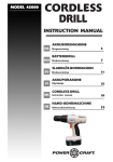
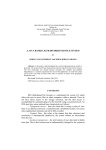
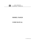
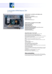
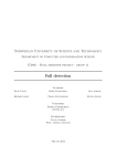
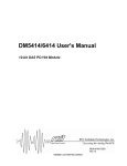
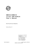
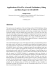
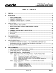
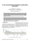
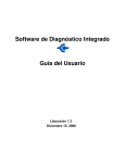
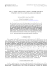
Virtual Library Included in LabVIEW Environment for a New DAS with Data
Transfer by LPT
Marius Brinzila1, Cristian Fosalau2, Codrin Donciu3, Mihai Cretu4
1
"Gh. Asachi" Technical University, Iasi, Faculty of Electrical Engineering, Bd. D. Mangeron, 53,
700050, Iasi, Romania, [email protected]
2
"Gh. Asachi" Technical University, Iasi, Faculty of Electrical Engineering, Bd. D. Mangeron, 53,
700050, Iasi, Romania, [email protected]
3
"Gh. Asachi" Technical University, Iasi, Faculty of Electrical Engineering, Bd. D. Mangeron, 53,
700050, Iasi, Romania, [email protected]
4
"Gh. Asachi" Technical University, Iasi, Faculty of Electrical Engineering, Bd. D. Mangeron, 53,
700050, Iasi, Romania, phone +40 232 278683, [email protected]
Abstract-In this work a data acquisition board (DAQB) with data transfer by parallel port LPT and
the associated virtual library included into LabVIEW software are presented. The DAQB developed
around a National Semiconductor LM 12458 device, have the capability to perform tasks that diminish
the host processor work and is capable to communicate with the host computer by using a set of drivers
associated. Highly integrated device circuit that has into it the most components of the board, facility in
data handling, good metrological performance and a very low cost are the benefits of the proposed
system. The novelty of the system consists in the drivers associated that assure the flexibility and the
portability of the system and in the fact that you can plug-in the DAQB to the running host computer
externally.
I. Introduction
The modern microcomputer technology has made it relatively simple to install, configure, and start
up a high-performance data acquisition system. Experienced users will be happy to know that many of
the problems encountered a few years ago are gone. New users will never realize how difficult it once
was to bring up a data acquisition system. These same technology advances have made it even more
difficult than ever to select among the many options. The hardware decisions facing a user today
require a great deal of study, analysis, and consideration. Every system will work, but some are better
than others for each particular application.
Most data acquisition hardware is compatible with most popular industrial software, or it comes with
a software package of its own. Virtually all these data acquisition devices and systems have the same
basic specifications and options on their data sheets: signal conditioning, number of analog input
channels, sampling rate, resolution, accuracy etc.
The most DAS’s used in instrumentation are made it by National Instrument, including the software.
These boards are plug-in types on ISA or PCI slots of the computers. In this case they will be affected
by electromagnetic field. The manufacturer has to take special protection measures that increase the
device costs.
Taking in consideration all this facts, we have developed a DAQB with data transfer by parallel port
LPT. A set of drivers and functions specially designed to by accessed in LabVIEW functions palette we
have made.
II. Data acquisition board
The data acquisition system is a low cost board realized around the chip LM12H458 that is an
integrated DAS and offers a self-calibrating 12-bit a sign A/D converter with choice of single ended,
fully differential, or mixed inputs, with on-chip differential reference, 8-input analog multiplexer,
sample-and-hold, an impressive, flexible programmable logic system and a choice of speed/power
combinations. The programmable logic has the circuitry to perform a number of tasks on its own,
freeing the host processor for other tasks. This logic includes:
1. An instruction RAM that allows the DAS to function on its own (after being programmed by the
host processor) with programmable acquisition time, input selection, 8-bit or 12-bit conversion
mode.
535
2.
Limit registers for comparison of the inputs against high and low limits in the “watchdog”
mode.
3. A 32-word FIFO register to store conversion results until read by the host.
4. Interrupt control logic with interrupt generation for 8 different conditions.
5. A 16-bit timer register.
6. Circuitry to synchronize signal acquisition with external events.
7. A parallel microprocessor/microcontroller interface with selectable 8-bit or 16-bit data access.
The board can be used to develop both software and hardware. Since the parallel port is limited to 8bit bidirectional data transfers, the BW pin is tied high for 8-bit access. Multiplexed address/data bus
architecture between the DAS and LPT is used.
Figure 1. The Virtual library and the architecture of data acquisition system.
The circuit operates on a single +5V supply derived from the external supply using an LM7805
regulator or from USB port. This greatly attenuates noise that may be present on the computer’s power
supply lines.
Digital and analog supply pins are connected together to the same supply voltage but they need
separate, multiple bypass capacitors. Multiple capacitors on the supply pins and the reference inputs
ensure a low impedance bypass path over a wide frequency range.
All digital interface control signals (/RD, /WR, ALE, /INT, /CS), data lines (DB0–DB7), address
lines (A0–A4) connections are made through the motherboard LPT connector using a standard LPT
cable. All analog signals applied to, or received by, the input multiplexer (IN0–IN7), VREF+, VREF−,
VREFOUT, and the SYNC signal input/ output are applied through a connector on the rear side of the
board.
The voltage applied to VREF− is GND and VREF+ is selected using a jumper. This jumper selects
between the LM12H458 internal reference output, VREFOUT, and the voltage applied to the
corresponding pin applies it to the LM12H458 VREF+ input.
The board can provide 4 current inputs by manually acting to the jumpers (JP). The conversion of
the unified currents into voltages is accomplished by precise resistors (R) calibrated for its own input.
A SYNK push button is available on the DAQB. With signal SYNC configured as an input, it is
possible to synchronize the start of a conversion to an external event. This is useful in applications such
as digital signal processing (DSP) where the exact timing of conversions is important.
Because the LM12H458 is so versatile, working with them may appear to be an overwhelming task.
However, gaining a basic understanding of the device will prove to be fairly easy and using it to be as
easy as programming the host microprocessor or microcontroller.
III. DAS programming model
The DAS is designed to be controlled by a processor, but the DAS functionality off loads most of the
data acquisition burden from the processor, resulting in a great reduction of software and processor
overhead. The processor downloads a set of operational instructions to the DAS RAM and registers,
and then issues a start command to the DAS, which performs conversions and/or comparisons as
indicated by the instructions, loading conversion results into the FIFO, while the processor is free to do
other chores, or can be idled, if not needed.
536
Figure 1 illustrates the functional block diagram or user programming model of the DAS.
Figure 2. DAS Functional Block Diagram.
The INSTRUCTION RAM is divided into 8 separate words of (3x16) bits. Each word consists of
three 16-bit sections, each with a unique address. The three different sections of each word are selected
by a 2-bit RAM Pointer (RP) for read/write operations. The RP is part of the Configuration Register.
The instruction section holds operational information such as the input channels to be selected, the
mode of operation of that instruction, and how long the acquisition time should be. The Limits sections
are used in the watchdog mode and hold user-defined limits. The DAS begins executing from
Instruction 0 and continues executing subsequent instructions up to any user specified instruction,
where it “loops back” to Instruction 0 or pauses, depending upon user programming. The cycle may be
repeatedly executed until stopped by the user, until the FIFO is full, or until the FIFO holds a user
programmed number of conversion results.
The FIFO Register is used to store the results of the conversions. This register is “read only” to the
user and all locations are accessed through a single address. Each a conversion is performed, the result
is stored in the FIFO. The internal FIFO writing and the external FIFO reading do affect each others
pointers.
The CONFIGURATION Register is the main “control panel” of the DAS. Writing data to the
Configuration Register the DAS to perform operations such as start or stop sequencer, reset the
pointers and flags, enter standby mode for low power consumption, calibrate offset and linearity, and
select RAM sections.
The INTERRUPT STATUS and LIMIT STATUS Registers are “read only” and are used to indicate
which conditions have generated the interrupt and what limits have been exceeded.
The TIMER Register is used to insert a delay before execution of any selected instruction(s). This
can be useful reducing the generation of redundant data when converting slowly changing signals.
The following typical procedure demonstrates the basic concepts of DAS programming:
1. Reset the DAS by setting the RESET bit and select RAM section “00” through the
Configuration Register.
2. Load instructions to the Instruction RAM (1 to 8 instructions).
3. Select RAM section “01” (if used) through the Configuration Register to program the first set
of watchdog limits.
4. Load limits 1, (if used).
5. Select RAM section “10” (if used) through the Configuration Register to program the second
set of watchdog limits.
6. Load limits 2, (if used).
7. Initialize the Interrupt Enable Register by selecting the conditions to generate an interrupt at the
INT pin (if interrupt used).
8. Program the Timer Register for required delay (if used).
9. Start the sequencer operation by setting the START bit in the Configuration Register. Set the
other bits in the Configuration Register at the same time, as required.
537
After the DAS starts operating, the processor may respond to interrupts from the DAS, or it may
interrogate the DAS at any time.
IV. Driver and LabVIEW library
Using LabVIEW software that has the capability to communicate with the parallel ports by using
Inport-Output functions a driver for this data acquisition board was made it. We created two basic
functions Write.vi (Scrie.vi) and Read.vi (Citeste.vi) which are the main functions when
communicating with DAQB. The Write and Read functions are used for writing and reading into/from
DAS registers. A basic function consists in a sequence of Outport and Inport functions. The port
address is one of the three buffers addresses of the parallel port.
The front panel and diagram of LabVIEW driver (basic functions) according with time diagrams are
presented in the figure 3
Figure 3.The basic functions of the virtual library: Write and Read
Based on functions Write and Read others complex functions are developed and consists in multiple
writing and reading operations into and from the board registers using the basic functions. Each is
responsible with specific procedures in the board operation. The complex functions of the virtual
library in LabVIEW environment include:
1. One Push One Channel (acquisition with external start conversion),
2. One Push Multi Channel (acquisition with external start conversion),
3. One Scan One Channel (acquisition without external start conversion),
4. One Scan Multi Channel (acquisition without external start conversion),
5. Waveform multi channel acquisition by interruption,
6. Watchdog/One Shot - multi channel acquisition,
7. Watchdog and alarm without acquisition for one or multi channel.
For LabVIEW, the functions are constituted as sub-VIs that are included into a separate acquisition
subpalette, part of the main function palette. The main function palette of the DAQB is LPT-DAS and
palette includes the fallowing subpalettes:
1. Analog Input with
• AI Utilities and
• AI Advanced subpalettes
2. Calibration and Configuration.
3. Timer
4. Signal Condit.
5. Wachdog
538
In figure 4 subpalette of Analog Input and Wachdog are presented.
Figure 4.The functions palette LPT DAS used for communicating with the new DAS.
The Analog Input subpalette functions contain other tow subpalette functions and simple functions
like Write, Read, Start, Stop or Reset (internal sequencer).
A programme example of temperature measurement in the Signal Conditioning subpalette is
presented. A Dataloger example you can find out in the AI Utilities.
Figure 5.Dataloger example.
Wachdog subpalette contains three functions: Low Limit, High Limit and Low & High Limit.
No conversion is performed in the watchdog mode, but the DAS samples the selected input(s) and
compares it/them with values of the low and high limits stored in the instruction RAM. This
comparison is done with a voltage comparator with one comparator input being the selected
multiplexer input (pair) and the other input being the appropriate tap on the internal capacitive ladder
of the converter. T his tap is selected by a programmed value in the instruction register. If the input
voltage is outside of the user defined and programmed minimum/maximum limits, an interrupt can be
generated to indicate a fault condition, and the host processor could then service that interrupt, taking
the appropriate action.
The flow diagram of the Wachdog One Channel without Acquisition.vi function will be presented. It
consists in multiple writing and one final reading operation into and from the board registers. First, the
reset operation has to be performed by selecting RAM section 0(RP=00) and write 0002H to
CONFIGURATION register. Next, is loading instruction to INSTRUCTION RAM (set the utilized
channel, the reference to ground or to other channel and the load impedance threshold. Afterwards,
select the RAM section 1(RP=01) and write 0100H to CONFIGURATION register. In this momentit is
possible to write the Superior Limit. Afterwards, select the RAM section 2(RP=10, write 0200H to
539
CONFIGURATION register) and write the Inferior Limit. Start the DAS conversion by setting D0 of
CONFIGURATION register high. Read the results of conversion from the Limit Status Register.
Figure 5.The flow chart of the Wachdog One Channel without Acquisition.vi.
The Limit Status Register is likewise cleared whenever (Limit Status Register) is read or a device
reset is issued.
IV. Conclusions
DAQB presented have the capability to perform tasks that diminish the host processor work and is
capable to communicate with the host computer by using a set of drivers associated in LabVIEW
software. The novelty of our work mostly consists in the drivers and functions associated which are
gathered into a library easily accessed by LabVIEW and assure the flexibility and the portability of the
system. One of the performances consist in the fact that you can plug-in the DAQB to the running host
computer externally
The proposed system is simple, versatile, flexible, cheap, high-speed digital data acquisition system
that combined with LabVIEW software, become a very useful measurement instrument.
References
[1] National Semiconductor, “Technical Information for LM12458 ”, July 1999
[2] National Semiconductor, Application Note 949, Nicholas Gray May 1994
[3] National Instruments, Measurement and Automation Catalogue, 2004.
[4] National Instruments, LabVIEW User Manual and G Programming, 2001.
[5] Foşalău C., Brînzilă M., Temneanu M., Niţă L., A digital acquisition board with data transfer by
parallel ports, Buletinul Institutului Politehnic din Iasi, Tomul L(LIV), Fasc.5, 2004, pp.826-829,
ISSN 1223-8139.
[6] M.C. Brinzila, M.Temneanu, M.Creţu, M.D.Pereira, C.Donciu, System for environmental
monitoring using a data acquisition board by parallel port, Buletinul Institutului Politehnic din Iasi,
Tomul L(LIV), Fasc.5, 2004, pp.737-742, ISSN 1223-8139.
540