Transcript
V303 / V305 / V307 / V310 / V313 | Gate Valve Lockout
User Manual
Material Content:
Gate Valve Lockout V303
1“ to 2,5“
Gate Valve Lockout V305
2,5“ to 5“
Gate Valve Lockout V307
5“ to 6,5“
Gate Valve Lockout V310
6,5“ to 10“
Gate Valve Lockout V313
10“ to 13“
Application:
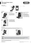
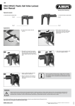
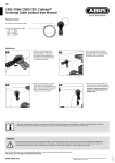
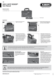
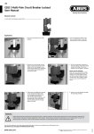
1. T urn off the valve.
1.
2. Place the gate value lockout device
around the valve handle.
2.
3. Insert a padlock through the opening
and lock it.
3.
4. Make sure that the valve handle is
correctly enclosed and can no longer
be operated.
For hand wheels with a spindle, it is possible to create a
passage in the center of the two halves of the lockout device.
To do so, release the points provided using a pair of pliers
(not applicable for V303).
Info 1.
Info 2.
WARNING:
Product should only be used by personnel properly trained in lockout procedures. Product should only be used on the appropriate application (s).
Follow product instructions for proper application of each product. Properly trained personnel should check to ensure that product is secure and
equipment will not operate. Failure to follow product instructions and warnings may result in serious bodily inury or death.
www.abus.com
Subject to technical alterations. No liability for mistakes and printing errors.
ABUS | D 58292 Wetter | Germany
©
07/2015
You will find additional notes and corresponding application videos to every lockout device following the link:
http://www.abus.com/eng/Service/Videos/Industrial-safety