Transcript
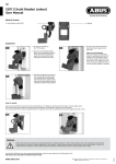
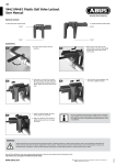
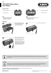
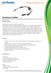
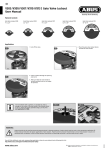
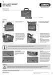
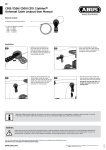
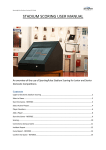
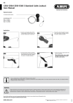
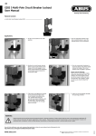
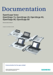
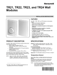
V423 / V426 | Metal Ball Valve Lockout
User Manual
Material Content:
a. Metal Ball Valve Lockout large V426
a. Metal Ball Valve Lockout small V423
Application:
1.
1. Turn the valve handle to the off
position.
2.
3.
3. P
osition lockout device tab over the
angled portion of the valve handle.
4.
2. Align and slide the lockout device
over the valve handle as far as
possible.
4. Squeeze the lockout device and the
valve handle together and insert
a padlock through the hole that
provides the tightest fit. Make sure
tab is against valve handle and
lower paddle is touching valve body
or pipe.
If the ABUS Ball Valve Lockout doesn’t fit, please use ABUS Ball
Valve Lockout Devices V442 or V448 as an alternative.
Verify that the lockout device and valve handle cannot be
manipulated to the “open” position. If the ball valve lockout
and/or the valve handle can be moved, the device was not
installed correctly or used with the appropriate size handle.
It is then required to reapply the device.
The given holes do not indicate the maximum number of locks
that can be used for the lockout device. To get the “closest
point,” it is only possible to hook one lock. If several locks
are needed, please use a safety hasp.
WARNING:
Product should only be used by personnel properly trained in lockout procedures. Product should only be used on the appropriate application (s).
Follow product instructions for proper application of each product. Properly trained personnel should check to ensure that product is secure and
equipment will not operate. Failure to follow product instructions and warnings may result in serious bodily inury or death.
www.abus.com
Subject to technical alterations. No liability for mistakes and printing errors.
ABUS | D 58292 Wetter | Germany
©
07/2015
You will find additional notes and corresponding application videos to every lockout device following the link:
http://www.abus.com/eng/Service/Videos/Industrial-safety