1
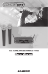
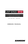
DIVERSITY WIRELESS SYSTEM
OWNERS MANUAL
®
Table of Contents
Introduction 3
System Features 4
QuickStart 6
Guided Tour - M32 Receiver 7
Guided Tour - T32 Beltpack Transmitter 10
Guided Tour - H32 Handheld Microphone
Transmitter 12
Setting Up and Using the Micro 32 System 14
Appendix A: T32 Multipin Wiring Guide
and Chart 18
Appendix B: Channel Plan 19
Specifications 20
Produced by On The Right Wavelength for Samson Technologies Corp.
Copyright 1999, Samson Technologies Corp.
Printed October 1999
Samson Technologies Corp.
575 Underhill Blvd.
P.O. Box 9031
Syosset, NY 11791-9031
Phone: 1-800-3-SAMSON (1-800-372-6766)
Fax: 516-364-3888
Introduction
Congratulations on purchasing the Samson Micro 32 Wireless System! Although this
product is designed for easy operation, we suggest you first take some time to go through
these pages so you can fully understand how we’ve implemented a number of unique
features.
Every wireless system consists of at least two components—a transmitter and a receiver,
both of which must be tuned to the same channel (that is, the same radio frequency) in
order to operate correctly.* The Samson Micro 32 system is frequency-agile; that is, it is
capable of operating over any of a number of selectable frequencies, making it eminently
suitable for touring setups or where multiple wireless systems need to be used
simultaneously. Specifically, it offers 32 different operating frequencies within each of
three bands (low, medium, or high), allowing up to six different Micro 32 systems to be
used simultaneously in one band. The system you have purchased contains an M32
micro diversity receiver and either our T32 belt-pack transmitter (for instrument or lavalier
microphone or headset applications) or H32 hand-held microphone transmitter (available in
a wide variety of popular capsules).
The Micro 32 system is specially designed to enable the production of professional audio
tracks to accompany your video shoot or live broadcast. The use of a handheld mic
transmitter or lavalier microphone connected to a beltpack transmitter effectively isolates
the performer from unwanted ambient sounds such as video camera motor noise or room
sounds made by the camera operator or video crew. Because the M32 receiver is
extremely small and lightweight, it can be attached easily to any video camera using the
supplied strip of velcro, and can even be powered directly by the camera’s own 12-volt
power supply, if available.
In this manual, you’ll find a QuickStart section (for those of you familiar with wireless audio
systems) as well as more detailed description of the features of the Micro 32 system, a
guided tour through all components, step-by-step instructions for setting up your system,
wiring diagrams and tables, a channel plan and full specifications. If your Micro 32 system
was purchased in the United States, you’ll also find a warranty card enclosed—don’t forget
to fill it out and mail it! This will enable you to receive online technical support and will
allow us to send you updated information about this and other Samson products in the
future. If your Micro 32 system was purchased outside of the U. S., contact your local
distributor for warranty details. Also, be sure to check out our website
(http://www.samsontech.com) for complete information about our full product line.
SPECIAL NOTE for U.S. purchasers: Should your Micro 32 system ever require servicing,
a Return Authorization number (RA) is necessary. Without this number, the unit will not be
accepted. If your Micro 32 system was purchased in the United States, please call
Samson at 1-800-372-6766 for a Return Authorization number prior to shipping your unit.
If possible, return the unit in its original carton and packing materials. If your Micro 32
system was purchased outside of the U. S., contact your local distributor for servicing
information.
* Your receiver and transmitter have been factory preset to utilize the same channel.
A listing of the available channels and their corresponding UHF frequencies is presented
in Appendix B on page 17 in this manual.
3
System Features
Designed for use in both live sound and sound contracting applications, the Samson UHF
Micro 32 Wireless System provides a high performance, cost effective solution, utilizing
state-of-the-art technology in wireless communications. Its main features include:
• Three bands of operation (low, medium and high), with 32 different available channels
per band, all operating in the less crowded UHF bandwidth. Up to six Micro 32 systems
(each tuned to a different frequency within the same band) can be used in the same
location without interference. (U.S. users, who can access both the low and medium
bands, have access to 64 channels and can use up to twelve Micro 32 systems in a
single location.)
• Optimized for use in videography applications, the Micro 32 system is highly
customizable, combining a UHF “walkaround” receiver with your choice of beltpack or
handheld microphone transmitters.
• Using the supplied velcro strip, the compact, lightweight M32 receiver can be easily
attached to any video camera and can even derive 12-volt power from the camera (if
available), making it easy to integrate into any traveling or fixed installation video system.
• The M32 micro diversity receiver includes a pair of tuned antennas and provides both
balanced and unbalanced outputs (with a three-position output level switch) and a
headphone monitor output with continuously adjustable level control. The receiver also
includes an audio peak LED, dual receiver indicators, and an RF strength meter.
• Technological breakthrough usage of SAW (Surface Acoustic Wave) filters (similar to
those used in high-end television receivers) for extremely precise and stable tuning.
• True Diversity technology maximizes active range (up to 300 feet) and reduces potential
interference problems through automatic switching between two independent receivers.
• Built-in companding noise reduction in all components for crystal-clear sound with
minimized background noise and hiss.
• Transmitters utilize PLL synthesized VCO technology to minimize spurious emissions
and provide “popless” muting, which turns off the audio signal while leaving the carrier
signal on. They use standard 9-volt batteries, with battery life of approximately 8 hours.
Transmitters also provide a convenient three-segment multicolor Battery Strength LED
meter, allowing you to monitor the remaining power in the installed battery.
• The H32 hand-held microphone transmitter is available in a selection of popular mic
capsules, including:
Samson QMIC dynamic
Audix OM-5 dynamic
Electro Voice ND 757A N/DYM dynamic
Electro Voice ND 857A N/DYM dynamic
Shure SM85 condenser
Shure SM87 condenser
4
System Features
• Compact “beeper-sized” T32 belt-pack transmitter is extremely lightweight (less than 4
ounces with a 9-volt battery installed). It provides a mini-XLR jack for connection to
guitar cables or a variety of popular headsets and lavalier microphones, including:
Samson QE headset*
Samson QV headset
AKG C-410 headset
Audio-Technica ATM-75 headset
Audio-Technica MT-350 lavalier
Audio-Technica Pro-35X wind microphone
Audio-Technica AT-831 lavalier
Countryman IsoMax headset
Crown CM-311(E) headset
Samson ECM-40 lavalier
Sennheiser MKE-2 lavalier
Sony ECM-44 lavalier
Sony ECM-55 lavalier
Sony ECM-77 lavalier
• All components have rugged construction that ensures reliable operation in even the most
demanding performance environments.
* Optimized for aerobics workouts, this headset is recommended for usage in
high-humidity environments such as physical fitness centers.
5
QuickStart
If you’ve had some prior experience using wireless systems, these QuickStart instructions
will get you up and running with your Micro 32 system in a matter of minutes! Detailed
instructions for setting up and using your Micro 32 system can be found on page 12 of this
manual, and the “Guided Tour” sections on pages 5 - 11 provide full descriptions of all
Micro 32 component controls and displays.
1. Make sure that the supplied M32 receiver and T32 or H32 transmitter are factory
preset to the same band (High, Medium or Low).
2. Physically place the M32 where it will be used (if desired, it can be connected to your
video camera using the supplied velcro strip) and extend both of its antennas vertically.
3. If you are using the T32 with a lavalier or headset microphone, make the physical
connection between its mini-XLR input connector and the microphone you are using.
4. Place a fresh battery in the transmitter and M32 receiver (or connect the M32 DC input
to your video camera’s 12 volt output or optional AC300R adapter) and turn it on
momentarily to check it; the multifunction LED will light green if the battery is sufficiently
strong.
5. Turn your audio system off and make the physical cable connection between the M32
balanced or unbalanced output jack (if necessary, both can be used simultaneously) and
the line or mic level audio input of your video camera, amplifier or mixer. If you are using
the balanced output jack, be sure to set the M32 Audio Output Level switch correctly.
6. Determine the best Group and Channel to use by setting the M32 meter to “RF” and
observing it while using the supplied plastic screwdriver to select different Groups and
available Channels within that Group (refer to Appendix B on page 17 in this manual for a
complete channel plan). Select a Group that has the greatest number of suitable
Channels and the Channel within that Group that has the greatest signal strength.
Remember that, when two or more transmitters and receivers are being used at the same
location, all devices must be set to the same Group (each to a different Channel).
7. Turn on the transmitter and use the supplied plastic screwdriver to set it to the same
Group and Channel you have selected for the receiver. Its multifunction LED will blink
when selecting an unavailable Channel within a Group.
8. Set the audio gain structure by speaking or singing into your mic (or playing your
instrument) at a normal performance level while slowly raising the audio input control of
your video camera or audio output level of your amplifier or mixer until the desired level is
reached. If necessary, use the supplied plastic screwdriver to adjust the transmitter’s AF
Level trimpot in order to increase or decrease its signal level.
9. Do a walkaround through the intended area of coverage while observing the M32’s RF
meter. Reposition it (or its antennas) or select a different Group/Channel as necessary.
10. If you hear any spurious noise from the M32 output when the transmitter is turned off,
use the supplied plastic screwdriver to adjust the M32 Squelch level control, slowly turning
it clockwise until the point at which the noise disappears.
6
Guided Tour - M32
1
A
2
3
1
UHF MICRO DIVERSITY RECEIVER
LOW
B
MID HIGH PEAK
SAMSON
4
5
MIN
SQ LEVEL
MAX
POWER
ON
+
2: Meter - This set of three multicolor LEDs
acts as a meter, indicating either battery
power or the strength of the incoming RF
signal. This meter can also be disabled
altogether to conserve battery power. See
#15 on the next page for more information.
-
6
1: A/B Receiver LEDs - When signal is
being received, one of these will be lit
orange, showing you whether the (left) “A”
or (right) “B” receiver is currently being
used. The M32 constantly scans its two
antennas and automatically selects
whichever is receiving the strongest,
clearest signal. This True Diversity
switching is completely inaudible, but it
effectively increases overall range while
virtually eliminating potential interference
and phase cancellation problems.
7
SAMSON
3: Peak LED - This LED lights red when
output signal from the M32 is at the onset of
clipping (that is, when it is on the verge of
being distorted). If you see this light during
operation, move the microphone further
away or lower the output level of your instrument or transmitter. For more information,
see the “Setting Up and Using the Micro 32
System” section on page 12 in this manual.
4: Power switch - Use this to turn the M32
power on and off.
5: SQ (Squelch) Level control - This control determines the maximum range of the
M32 before audio signal dropout. Although it can be adjusted using the supplied plastic
screwdriver, it should normally be left at its factory setting. See the “Setting Up and
Using the Micro 32 System” section on page 12 in this manual for more information.
6: Battery holder - Insert a standard 9-volt alkaline battery here, being sure to observe
the plus and minus polarity markings shown. We recommend the Duracell MN 1604
type battery. Although rechargeable Ni-Cad batteries can be used, they do not supply
adequate current for more than four hours. WARNING: Do not insert the battery
backwards; doing so can cause severe damage to the M32 and will void your warranty.
7: Plastic screwdriver - Specially designed for use in adjusting the M32 Squelch Level
control (see #5 above). See the “Setting Up and Using the Micro 32 System” section on
page 12 in this manual for more information.
7
Guided Tour - M32
8
8: Antennas (A and B) - The antenna
mountings allow full rotation for optimum
placement. In normal operation, both
antennas should be placed in a vertical
position. Both antennas can be folded
inward for convenience when transporting
the M32. See the “Setting Up and Using
the Micro 32 System” section on page 12
in this manual for more information.
9 10 11
DC INPUT
OUT UNBAL
LEVEL
30 20 10
9: DC input - This jack will accept a DC input voltage of 6 - 13 volts (inner connection [tip]
positive, outer connection [sleeve] ground) from your video camera, if available. Connect
the optional Samson AC300R adapter here to charge a rechargeable 9-volt Ni-Cad battery.
10: Unbalanced output* - Use this unbalanced (1K Ohm max.) 1/8" (3.5 mm) mini-phone
jack when connecting the M32 to consumer (-10) audio equipment. Wiring is as follows:
tip hot, sleeve ground. If your video camera has stereo audio inputs, you’ll need to use a
Y-adapter that has a 1/8" (3.5 mm) mini-phone plug at one end and dual male RCA-type
plugs at the other end.
11: Audio Output Level switch - Sets the audio output level of both the balanced and
unbalanced outputs (see #10 above and #14 below) to -30 dBm (mic level), -20 dBm, or
-10 dBm (line level). See the “Setting Up and Using the Micro 32 System” section on page
12 in this manual for more information.
12
LANCED
BA
PHONES LEVEL
P
OUT UT
13
14
METER
BATT.
RF
OFF
12: Level control - This knob sets the
level of the audio signal being sent to
the headphones output (see #13
below).
15
13: Headphones output - Connect a
stereo headphone to this standard
1/8" (3.5 mm) mini-phone jack in order
to monitor the signal being output by the M32. We recommend the use of 30 ohm
headphones. The level of the headphone signal can be set by adjusting the Level control
(see #12 above). Maximum output is 240 mW @ 30 ohms).
14: Balanced output* - Use this electronically balanced low impedance (600 Ohm)
mini-XLR jack when connecting the M32 to professional (+4) audio equipment. Pin wiring
is as follows: Pin 1 ground, Pin 2 high (hot), and Pin 3 low (cold).
15: Meter switch - This three-position switch determines the function of the M32 meter
(see #2 on the previous page). In the left “RF” position, the meter indicates the strength of
the incoming RF signal. In the center “BATTERY” position, the meter indicates relative
battery power, showing whether the installed battery is at low (red), mid (yellow) or high
(green) strength. (Note: When the red “low” indicator lights, performance is degraded and
the battery needs to be replaced). In the right “OFF” position, the meter is disabled
altogether, thus conserving battery power.
* If required, both the unbalanced and balanced outputs can be used simultaneously.
8
Guided Tour - M32
16 17
CHANNEL
6
3
8
2
6
8
3
5
7
7
2
4
1
5
0
4
9
GROUP
16: Group selector - Use the supplied
plastic screwdriver to set this to the desired
Group.
17: Channel selector - Use the supplied
plastic screwdriver to set this to the desired
Channel. Note that only certain Channels
are available within each Group; for more
information, see Appendix B on page 17 in
this manual.
9
0
1
UHF MICRO DIVERSITY RECEIVER
FCC ID:CCRUM1
DOC ID:CAN
SAMSON Technologies Corp.
9
Guided Tour - T32
1
2
3
T32
INPUT
6
8
7
MAX
1
2
GROUP
CH
AF LEVEL
WARNING:
BE SURE TO OBSERVE
CORRECT BATTERY
POLARITY. DURACELL
MN1604 ALKALINE 9VDC
BATTERY RECOMMENDED
POWER
+
5
-
4
MIN
SAMSON
9
10
1: Antenna - This permanently attached transmitter “pig tail” antenna should be fully
extended for normal operations. See the “Setting Up and Using the Micro 32 System”
section on page 12 in this manual for more information about antenna positioning.
2: Multifunction LED - This multicolor LED serves several functions. First, it lights
whenever the T32 is powered on (see #7 on the next page). Secondly, whenever the T32
is powered on, it shows the relative battery power, indicating whether the installed battery
is at low (red), mid (orange) or high (green) strength. When it lights steadily red (“low”),
RF performance is degraded and the battery needs to be replaced. Finally, the LED
blinks whenever an unavailable Channel within a Group is selected. See #5 on the
following page for more information and Appendix B on page 17 in this manual for a
complete channel plan.
3: Input connector - The input device (instrument cable, lavalier mic, or headset mic) is
connected to this mini-XLR jack. See Appendix A on page 16 for more information.
4: Group selector - Use the supplied plastic screwdriver (see #9 on the following page)
to set this to the desired transmission frequency Group.
10
Guided Tour - T32
5: Channel selector - Use the supplied plastic screwdriver to set this to the desired
Channel. When two or more transmitters and receivers are being used in the same
location, they should be set up to use different Channels within the same Group. Note that
the T32 multifunction LED (see #2 on the preceding page) blinks whenever an unavailable
Channel within a Group is selected. See the “Setting Up and Using the Micro 32 System”
section on page 12 and Appendix B on page 17 in this manual for more information.
6: AF Level control (trimpot) - If necessary, you can use the supplied plastic
screwdriver (see #9 below) to raise or lower the T32 input level. See the “Setting Up and
Using the Micro 32 System” section on page 12 in this manual for more information.
7: Power on-off switch* - Use this to turn the T32 on or off (to conserve battery power,
be sure to leave it off when not in use).
8: Battery holder - Insert a standard 9-volt alkaline battery here, being sure to observe
the plus and minus polarity markings shown. We recommend the Duracell MN 1604 type
battery. Although rechargeable Ni-Cad batteries can be used, they do not supply
adequate current for more than four hours. WARNING: Do not insert the battery
backwards; doing so can cause severe damage to the T32 and will void your warranty.
9: Plastic screwdriver - Specially designed for use in adjusting the T32 AF Level control
(see #6 above) and/or M32 Squelch control (see #5 on page 5). See the “Setting Up and
Using the Micro 32 System” section on page 12 in this manual for more information.
10: Battery door - The T32 battery door is hinged and not intended to be removed from
the transmitter case. To open it, press gently inwards on the two tabs marked “Open” on
either side of the door. See the “Setting Up and Using the Micro 32 System” section on
page 12 in this manual for more information.
11: Audio on-off switch - When set to the “on” position, audio signal is transmitted.
When set to the “off” position, the audio signal is muted. Because the carrier signal
remains during muting, no “pop” or “thud” will be heard. Note that turning this off does not
turn off the transmitter power—it is simply a way to temporarily mute the transmission of
audio signal. If you don’t plan on using the transmitter for extended periods, turn off the
transmitter power by using the power on-off switch (see #7 above).
* Be sure to mute the audio signal at your external mixer or amplifier before turning
transmitter power on or off, or an audible pop may result.
3
2
11
OFF AUDIO ON
11
1
Guided Tour - H32
AU D I O
ON
OFF
2
1
LOW MID HIGH
B AT T. L E V E L
+
ALKALINE IS RECOMMENDED
9V BATTERY DURACELL MN1604
IMPORTANT
BATTERY POLARITY
1: Audio on-off switch - When set to
the “on” position, audio signal is
transmitted. When set to the “off”
position, the audio signal is muted.
Because the carrier signal remains during
muting, no “pop” or “thud” will be heard.
Note that turning this off does not turn off
the transmitter power—it is simply a way
to temporarily mute the transmission of
audio signal. If you don’t plan on using
the transmitter for extended periods, turn
off the transmitter power by using the
power on-off switch (see #3 below).
BE SURE TO OBSERVE CORRECT
H32M
5
-
POWER
ON
AF LEVEL
3
MIN
MAX
4
2: Multifunction LED - This multicolor
LED serves several functions. First, it
lights whenever the H32 is powered on
(see #3 below). Secondly, whenever the
H32 is powered on, it shows the relative
battery power, indicating whether the
installed battery is at low (red), mid
(orange) or high (green) strength.
When it lights steadily red (“low”), RF
performance is degraded and the battery
needs to be replaced. Finally, the LED
blinks whenever an unavailable Channel
within a Group is selected. See #7 on
the following page for more information
and Appendix B on page 17 in this
manual for a complete channel plan.
3: Power on-off switch* - Use this to turn the H32 on or off (to conserve battery power,
be sure to leave it off when not in use).
4: AF Level control (trimpot) - This input sensitivity control has been factory preset to
provide optimum level for the particular microphone capsule provided with your Micro 32
system and so we recommend that this not be adjusted manually. If necessary, however,
you can use the supplied plastic screwdriver to raise or lower the input level. See the
“Setting Up and Using the Micro 32 System” section on page 12 in this manual for more
information.
* Be sure to mute the audio signal at your external mixer or amplifier before turning
transmitter power on or off, or an audible pop may result.
12
Guided Tour - H32
FCC ID: CCRH32M
Te ch n o l o g i e s C o r p . D O C I D : C A N 0 0 0 0 0 0 0 0 0 0
BA999
Z
T999N
5: Battery holder - Insert a standard
9-volt alkaline battery here, being sure to
observe the plus and minus polarity
markings shown. We recommend the
Duracell MN 1604 type battery. Although
rechargeable Ni-Cad batteries can be
used, they do not supply adequate current
for more than four hours.
WARNING: Do not insert the battery
backwards; doing so can cause severe
damage to the H32 and will void your
warranty.
TRANSMITTER MODEL H32
Note: As shown in the illustration on the
left, the controls for setting the H32 Group
and Channel indicated below are located
on the opposite side to the battery
compartment:
8 7
6
5 4
CH
0 9
5 4
3 2 1
3 2 1
GR
8 7
6
0 9
6: Group selector - Use the supplied
plastic screwdriver to set this to the
desired transmission frequency Group.
7: Channel selector - Use the supplied
plastic screwdriver to set this to the
desired Channel. When two or more
transmitters and receivers are being used
in the same location, they should be set up
to use different Channels within the same
Group. Note that the H32 multifunction
LED (see #2 on the preceding page) blinks
whenever an unavailable Channel within a
Group is selected. See the “Setting Up
and Using the Micro 32 System” section
on page 12 and Appendix B on page 17 in
this manual for more information.
7
6
13
Setting Up and Using the
Micro 32 System
The basic procedure for setting up and using your Micro 32 Wireless System takes only a
few minutes:
1. For the Micro 32 system to work correctly, both the receiver and transmitter must be
set to the same band (labeled “Low,” “Medium” and “High”). Remove all packing materials
(save them in case of need for future service) and check to make sure that the supplied
M32 receiver and T32 or H32 transmitter are factory preset to the same band. If these do
not match, contact your distributor or, if purchased in the United States, call Samson
Technical Support at 1-800-372-6766.
2a. If you are using a 9-volt battery to power the M32, press gently down on the battery
door release (on the front of the M32, on the word “Open”) and swing the door open in
order to access the battery compartment . Note that the door is hinged and is not
intended to be removed from the receiver case. Insert a 9-volt battery, being careful to
observe the polarity markings. Warning: Reversing the battery polarity may cause
permanent damage to your receiver. Turn the power switch “On” and set the Meter
switch to “BATTERY.” The green “HIGH” meter LED will light if the battery is sufficiently
strong. Once you’ve verified battery strength, turn the power switch “Off” again.
2b. If you are using the optional Samson AC300R adapter or your video camera’s 12-volt
power supply to power the M32, connect it to the M32 DC input jack. On the front of the
M32, press gently down on the battery door release (on the word “Open”) and swing the
door open note that the door is hinged and is not intended to be removed from the
receiver case). Make sure the power switch is set to “Off.”
3. If you are using the T32 beltpack transmitter with a permanently attached instrument
cable, skip ahead to step 4a below. If you are using the T32 with a lavalier or headset
microphone, make the physical connection between its mini-XLR input connector and the
microphone you are using. Because the mini-XLR plug is “keyed,” you’ll need to rotate it a
certain way to get it to “mate” with the connector mounted on the T32; then push straight
down until you hear a click. To remove the mini-XLR connector, press in the black dot on
the plug and pull straight out (do not use force!). Never pull on the wire, only the plug
itself (with the black dot pressed in).
4a. If your system contains a T32 belt-pack transmitter, make sure its pigtail antenna is
extended fully and then press gently inwards on the two tabs marked “Open” (on the sides
of the case) to open the battery door, which is hinged and not intended to be removed
from the transmitter case. Please use care when opening this door as undue force will
destroy the hinge.
4b. If your system contains a H32 handheld transmitter, unscrew the bottom section of
the microphone by turning it counterclockwise and then slide it off.
5. Place a fresh 9-volt alkaline battery in the transmitter battery holder, taking care to
observe the polarity markings. If you are using a T32 belt-pack transmitter, gently replace
the battery door by swinging it up and pressing until it clicks. If you are using a H32
handheld transmitter, replace the bottom section of the microphone by sliding it on and
then screwing it back on. Whichever transmitter you are using, leave it off for the moment.
14
Setting Up and Using the
Micro 32 System
6. To check the battery strength, turn on the power to the T32 or H32 transmitter (using its
Power on-off switch). The multifunction LED will light green if the battery is sufficiently
strong. Once you’ve established that the installed battery has sufficient power, use the
Power on-off switch to turn the transmitter off again.
7. Make the physical cable connection between the output of your M32 receiver and the
audio input of your video camera or audio amplifier or mixer, being careful to set the Audio
Output Level switch so that the signal is strong but not distorting. Normally, it should be set
to the “-30” position when connecting to a mic-level input and to the “-20” or “-10” position
when connecting to a line-level input. If required, both the balanced and unbalanced
outputs can be used simultaneously. Leave your amplifier (and/or mixer) off at this time.
8. Next, select the Group and Channel for your transmitters and receivers. When two or
more transmitters and receivers are being used at the same location, all devices must be
set to the same Group (though each transmitter/receiver pair must use its own Channel) or
intermodulation noise may occur. With the power to your transmitter off, set the M32 Meter
switch to the left “RF” position, then use the supplied plastic screwdriver to set the M32
Group and Channel trimpots to an available channel within a Group. (Refer to Appendix B
on page 17 in this manual for a complete channel plan.) Next, turn on the transmitter and
set it to the same Group and Channel (its multifunction LED will blink whenever an
unavailable Channel within a Group is selected). One or more segments in the M32 meter
should then light. If the “HIGH” segment lights, the M32 is receiving an optimally strong
RF signal. If the “LOW” segment lights (indicating a relatively weak RF signal), try a
different Channel within the Group or a different Group/Channel altogether—you will find
that some have stronger signals than others. Always pick the Channel that has the
strongest signal.
9. Next, it’s time to set the audio gain structure. Turn on your connected amplifier and/or
mixer but keep its volume all the way down. Make sure that your transmitter is unmuted by
setting its Audio switch to “On.” If you are using the H32 transmitter or if you are using the
T32 transmitter with a connected lavalier microphone or headset, speak or sing into the mic
at a normal performance level while slowly raising the volume of your amplifier/mixer until
the desired level is reached. If you are using the T32 transmitter with a connected instrument, play the instrument at normal performance level while slowly raising the volume of
your amplifier/mixer until the desired level is reached. If you are using a lavalier microphone, correct placement is critical to sound quality.
We recommend that you position it as shown in the
illustration on the right—as close to your mouth as
possible but off to one side (to minimize nasality) and
unobstructed by clothing. Bear in mind also that
omnidirectional microphones (mics which pick up
signal from all directions) are more prone to feedback
problems than unidirectional (cardioid or supercardioid) ones; in general, you can avoid feedback by
taking care not to use any microphone directly in front
of a PA speaker (if this is unavoidable, you can try
using an equalizer to attenuate those high frequencies
which are causing the feedback “squealing”).
T32
INPUT
SAMSON
15
Setting Up and Using the
Micro 32 System
10. If you hear distortion at the desired volume level, first check to see whether the red
“Peak” LED on the M32 is lighting. If it is not, make sure that the gain structure of your
audio system is correctly set (consult the owners manual of your mixer and/or amplifier for
details). If the red “Peak” LED does light, do the following:
• If you are using an H32 transmitter, use the supplied plastic screwdriver to turn its AF
Level control (trimpot) slowly counterclockwise (towards the “Min” position) until the
distortion disappears.
• If you are using a T32 transmitter with connected lavalier microphone or headset, its
AF Level control has been factory preset to provide optimum level for the particular
lavalier or headset model being used and so no adjustment should be necessary. Any
distortion present should therefore simply be a matter of the microphone being too
close to the mouth; try moving it further away. If this does not solve the problem, use
the supplied plastic screwdriver to turn the AF Level control (trimpot) on the T32 slowly
counterclockwise until the distortion disappears. If you are using a T32 transmitter
with an instrument such as electric guitar or bass, lower the output level of the
instrument until the distortion disappears. Alternatively, you can use the supplied
plastic screwdriver to turn the AF Level control (trimpot) on the T32 slowly
counterclockwise until the distortion disappears.
11. Conversely, if you hear a weak, noisy signal at the desired volume level, again make
sure that the gain structure of your audio system is correctly set (consult the owners
manual of your mixer and/or amplifier for details). If it is and the signal coming from the
M32 is still weak and/or noisy, do the following:
• If you are using an H32 transmitter, use the supplied plastic screwdriver to turn the AF
Level control (trimpot) on the transmitter slowly clockwise (towards the “Max” position)
until the signal reaches an acceptable level.
• If you are using a T32 transmitter with connected lavalier microphone or headset, its
Level control has been factory preset to provide optimum level for the particular
lavalier or headset model being used and so no adjustment should be necessary.
Any weakness of signal should therefore simply be a matter of the microphone being
too far from the mouth; try moving it closer. If this does not solve the problem, use the
supplied plastic screwdriver to turn the AF Level control (trimpot) on the T32 slowly
clockwise until the signal reaches an acceptable level. If you are using a T32
transmitter with an instrument such as electric guitar or bass, raise the output level of
the instrument until a good signal is achieved. Alternatively, you can use the supplied
plastic screwdriver to turn the AF Level control (trimpot) on the T32 slowly clockwise
until the signal reaches an acceptable level.
12. If you want to use headphones to monitor the transmission, connect a standard
“Walkman”-type 30 ohm headphone to the M32 headphone output and adjust the Level
control until the desired level is reached.
13. When first setting up the Micro 32 system in a new environment, it’s always a good
idea to do a walkaround in order to make sure that coverage is provided for your entire
performance area. Accordingly, turn on both the transmitter and M32 receiver. If you are
using a video camera, use the supplied velcro strip to attach the M32 to the side of the
16
Setting Up and Using the
Micro 32 System
camera. If not, physically place the M32 in the position in which it will be used. Next, with
the transmitter unmuted, walk through the entire area that will need to be covered while
speaking, singing, or playing your instrument. As you do so, you will find that the orange
“A” and “B” LEDs on the M32 occasionally switch on or off, always showing you which
antenna is receiving the stronger signal. The basic rule of thumb for successful wireless
installations is to always try to minimize the distance between transmitter and receiver as
much as possible and also to try to maintain “line of sight” between the two (so that the
person using the transmitter can see the receiver antennas). You may also be able to
improve RF reception by relocating the receiver or repositioning one or both of the receiver
antennas.
13. Temporarily turn down the level of your mixer/amplifier system and turn off the power
to your transmitter, leaving the M32 on. Then restore the previously set level of your
mixer/amplifier. With the transmitter off, the receiver output should be totally silent—if it is,
skip ahead to the next step. If it isn’t (that is, if you hear some noise), you may need to
adjust the M32 Squelch level control. When the Squelch level control is at its minimum
setting, the Micro 32 system always provides maximum range without dropout; however,
depending upon the particular environment your system is used in, you may need to
reduce that range somewhat in order to eliminate band noise when the transmitter is
turned off. To do so, use the provided screwdriver to rotate the Squelch level control
completely counterclockwise (to the “Min” position), then slowly turn it clockwise until the
noise disappears. If no noise is present at any position, leave it at its fully counterclockwise “Min” position (so as to have the greatest overall range available).
If you have followed all the steps above and are experiencing difficulties, contact your
local distributor or, if purchased in the United States, call Samson Technical Support
(1-800-372-6766) between 9 AM and 5 PM EST.
17
Appendix A: T32 Multipin
Wiring Guide and Chart
1
MANUFACTURER
SAMSON
2
3
4
MODEL
ECM40
PIN 1
PIN 2
PIN 3
SHIELD
WHITE
JUMP TO PIN 2
QE/QV
SHIELD
WHITE
RED
JUMP TO PIN 2
C410
SHIELD
RED
WHITE
JUMP TO PIN 2
AUDIO TECHNICA
AT831
YELLOW x 2
SHIELD
RED x 2
JUMP TO PIN 2
AUDIO TECHNICA
ATM75
YELLOW x 2
SHIELD
RED x 2
JUMP TO PIN 2
AUDIO TECHNICA
ATPRO8HE
YELLOW x 2
SHIELD
N/C
RED x 2
AUDIO TECHNICA
ATPRO35X
YELLOW x 2
SHIELD
RED x 2
JUMP TO PIN 2
AUDIO TECHNICA
MT350
SHIELD
WHITE
JUMP TO PIN 2
COUNTRYMAN
ISOMAX
SHIELD
WHITE
JUMP TO PIN 2
CM311(E)
SHIELD
WHITE
RED
JUMP TO PIN 2
RED
JUMP TO PIN 2
SAMSON
AKG
CROWN
SENNHEISER
MKE2
SHIELD
BLUE
SENNHEISER
MKE40
SHIELD
BLUE
RED
JUMP TO PIN 2
SENNHEISER
MKE48
SHIELD
BLUE
RED
JUMP TO PIN 2
ECM44/55
SHIELD
WHITE
RED
JUMP TO PIN 2
RED
JUMP TO PIN 2
SONY
SONY
ECM77
SHIELD
WHITE
SONY
ECM144
SHIELD
WHITE
JUMP TO PIN 2
SHIELD
N/C
AUDIO
GROUND
+Vdc
AUDIO
GUITAR
PIN INFORMATION
Procedure for wiring T32 connector: Unscrew rubber boot 1 and pass
wire through 1 and 2. Solder wire to 3 after removing from 4 (use chart
above). Reinsert 3 to 4 with attached wire (3 is keyed to fit 4). Plug 2 into
3 again (2 is keyed to 3) and crimp wire. Rescrew rubber boot 1 to 4.
18
Appendix B: Channel Plan
Low Band (MHz):
Chan.:
Grp. 0
Grp. 1
Grp. 2
Grp. 3
Grp. 4
Grp. 5
Grp. 6
Grp. 7
Grp. 8
Grp. 9
0
778.125
779.375
780.625
781.875
1
778.375
778.125
778.250
778.625
778.750
779.625
778.250
779.500
780.750
782.000
2
778.875
778.375
778.500
778.875
779.500
780.125
778.375
779.625
780.875
3
780.125
779.125
779.000
779.375
780.000
780.375
778.500
779.750
781.000
4
780.750
779.750
779.875
780.250
781.125
780.750
778.625
779.875
781.825
5
781.500
781.000
780.500
780.625
781.375
781.625
778.750
780.000
781.250
6
7
8
9
781.750
781.500
780.875
781.250
781.750
778.875 779.000 779.125 779.250
780.125 780.250 780.375 780.500
781.375 781.500 781.625 781.750
Medium Band (MHz):
Chan.:
Grp. 0
Grp. 1
Grp. 2
Grp. 3
Grp. 4
Grp. 5
Grp. 6
Grp. 7
Grp. 8
Grp. 9
0
801.125
802.375
803.625
804.875
1
801.375
801.125
801.250
801.625
801.750
802.625
801.250
802.500
803.750
805.000
2
801.875
801.375
801.500
801.875
802.500
803.125
801.375
802.625
803.875
3
803.125
802.125
802.000
802.375
803.000
803.375
801.500
802.750
804.000
4
803.750
802.750
802.875
803.250
804.125
803.750
801.625
802.875
804.125
5
804.500
804.000
803.500
803.625
804.375
804.625
801.750
803.000
804.250
6
7
8
9
804.750
804.500
803.875
804.250
804.750
801.875 802.000 802.125 802.250
803.125 803.250 803.375 803.500
804.375 804.500 804.625 804.750
High Band (MHz):
Chan.:
0
Grp. 0
Grp. 1
Grp. 2
Grp. 3
Grp. 4
Grp. 5
Grp. 6
Grp. 7
Grp. 8
Grp. 9
856.500
856.500
854.900
855.400
855.900
856.400
856.900
857.400
857.900
858.400
1
857.025
857.025
854.950
855.450
855.950
856.450
856.950
857.450
857.950
858.450
2
857.500
857.500
855.000
855.500
856.000
856.500
857.000
857.500
858.000
858.500
3
858.250
858.250
855.050
855.550
856.050
856.550
857.050
857.550
858.050
858.550
4
858.700
858.700
855.100
855.600
856.100
856.600
857.100
857.600
858.100
858.600
19
5
6
7
8
9
857.625 857.950 858.200 858.650
855.150
855.650
856.150
856.650
857.150
857.650
858.150
858.650
855.200
855.700
856.200
856.700
857.200
857.700
858.200
858.700
855.250
855.750
856.250
856.750
857.250
857.750
858.250
858.750
855.300
855.800
856.300
856.800
857.300
857.800
858.300
858.800
855.350
855.850
856.350
856.850
857.350
857.850
858.350
858.850
Specifications
System Specifications:
Channels
Frequency Type
Modulation Type
Noise Reduction Type
Distance
32 per band (3 bands)
F3E
FM
Compander
100 meters from visible receiver
Transmitter (H32, T32):
Oscillation Type
Modulation Type
Pre-emphasis
Antenna
Input (T32)
Maximum Input Level
Battery
Battery life
Operating Temperature
Switches / Controls
Display (LED)
Operating Voltage
Current Consumption
RF Output Power
Frequency Stability
Spurious Ratio
Deviation
T.H.D. (Overall)
AF Frequency Response
Input Impedance
Dimensions
H32
T32
Weight
H32
T32
Crystal-controlled PLL frequency synthesized
Variable reactance
50 µsec
1/4 wave length; H32: integral dipole; T32: wire (permanently attached)
MIC input with phantom power,
INST input jack (27 dB attenuator at MIC input terminal)
-8 dBv
Duracell MN1604 9-volt alkaline
8 hours @ 25° C (without phantom power)
0° C / 50° C
Power ON/OFF, Audio ON/OFF
Group switch, Channel switch, Level volume
Battery Low/Mid/High (corresponds to <5.3 V / 5.3 - 7 V / >7V)
9 Volts +20% / -40%
55 mA
10 mW
±15 kHz
1 uW
15 kHz (13 kHz - 17 kHz)
2% max (@1 kHz, DEV 15 kHz)
50 Hz - 15 kHz (±3.5 dB overall)
H32: 100 Ohms; T32: 82. k Ohms (MIC input), 8.2 k Ohms (INST input)
(without microphone head) 37 mm (Dia) x 151 (H) (1.4 x 5.9 in.)
102 mm (W) x 66 (H) x 24 (D) (4 x 2.6 x .9 in.)
(without battery, microphone head): 65 grams • 2.3 oz.
(without battery, input cable): 80 grams • 2.8 oz.
Receiver (M32):
Oscillation Type
Receiving Method
De-emphasis
IF Frequency
Local Frequency
Antenna
In/Out
Crystal Controlled
Single Super Heterodyne / True Diversity
50 µsec
10.7 MHz
70 MHz Range (79 - 79.5 MHz)
1/4 Wavelength Rod
5.5 DC Inlet, Balanced Output (Switchcraft TA3F mini-XLR),
Unbalanced Output (3.5 mm phone jack), Headphone Output (3.5 mm phone jack)
Display (LED)
Receiver A/B (Orange), Peak (Red), RF Level / Battery Strength (3 pc)
Peak LED lighting point
AF output level approx. +4 dB
Controls
Group switch, Channel switch, Audio Level switch,
Squelch volume, Headphone volume, Meter function switch
Operating Temperature
0° C / 55° C
Operating Voltage
AC adapter DC 6 - 13 Volts, 9 volts battery
Current Consumption
>60 mA (no signal, all LEDs off)
Receiving Frequency Range
778.125 - 858.850 MHz
Squelch Sensitivity
17 dBµv ±4 dB
T.H.D. (Overall)
1% Max (@AF 1 kHz, RF 56 dBuv)
Dynamic Range
95 dB (w/IHF-A Filter)
AF Frequency Response
50 Hz - 15 kHz (±3 dB overall)
Audio Output Level
0 dBv ±2 dB (Maximum +9 dBV ±3 dB @ 3% THD)
Audio Output Impedance
1 k Ohms max. (Unbalanced), 600 Ohms (Balanced)
Headphone Output Impedance
32 Ohms
Battery life
12 hours typical
20
FCC Rules and Regulations
Samson wireless systems are type accepted under
FCC rules parts 90, 74 and 15.
Licensing of Samson equipment is the user’s
responsibility and licensability depends on the user’s
classification, application and frequency selected.
This device complies with RSS-210 of
Industry & Science Canada.
Operation is subject to the following two conditions:
(1) this device may not cause harmful interference
and (2) this device must accept any interference
received, including interference that may cause
undesired operation.